

Page 1

Grand Rapids, Michigan, U.S.A. 49504-5298
USER’S OPERATING AND INSTRUCTION MANUAL
MODEL 702
MODEL 702-SE
MODEL 702-SS
BUN SLICERS
0702S20000-CVR
Page 2

MODEL 702, 702SE and 702SS BUN SLICERS
INDEX
SLICER SPECIFICATIONS........................................................................ 0702S20019
Description .................................................................................... 0702S20019-1/2
Specifications ............................................................................... 0702S20019-1/2
Product Capacities ........................................................................ 0702S20019-2/2
SAFETY INSTRUCTIONS.......................................................................... 0702S20020
DEFINITIONS ........................................................................................... GEN 931118
ADJUSTMENTS........................................................................................ 0702S20022
Outside Side Guide ....................................................................... 0702S20022-1/2
Table Height .................................................................................. 0702S20022-1/2
Inside Side Guide .......................................................................... 0702S20022-1/2
Slow-Down Door ........................................................................... 0702S20022-2/2
OPERATING INSTRUCTIONS.................................................................. 0702S20023
MAINTENANCE/CLEANING/LUBRICATION............................................. 0702S20010
CHANGING THE BLADE........................................................................... 0702S20028
TROUBLE SHOOTING ............................................................................. 0702S20024
PARTS LIST.............................................................................................. 0702S20026
ASSEMBLY DRAWING MODEL 702 SLICERS ....................................... 0702S20021
ASSEMBLY DRAWING MODEL 702SE SLICERS .................................. 0702S20029
ASSEMBLY DRAWING MODEL 702SS SLICERS .................................. 0702S20030
WIRING DIAGRAMS ................................................................................ 0702S20025
WARRANTY.............................................................................................. GEN 040225
WARRANTY PROCEDURE .................................................................... GEN 040226
RETURN PARTS POLICY ...................................................................... GEN 040227
REV. 8-28-96 0702S20027
Page 3
MODEL 702, 702SE and 702SS BUN SLICERS
SPECIFICATIONS
DESCRIPTION
These bun slicers have welded steel frames and stainless steel chutes. They are
compact, durable slicers for counter top use in slicing a variety of buns with speed and
economy.
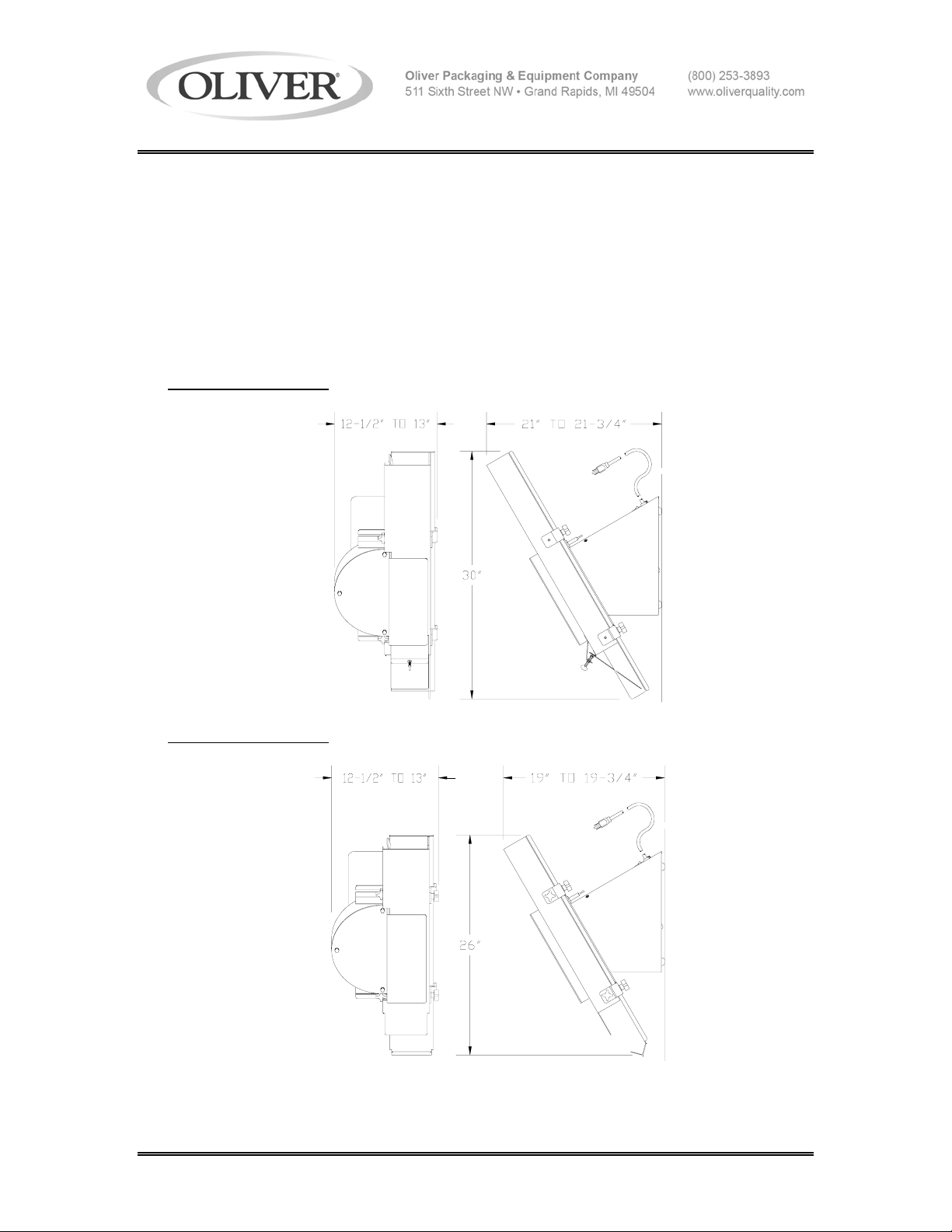
SPECIFICATIONS
• Machine dimensions:
Model 702
• Machine dimensions:
Model 702SE
REV. 8-28-96 0702S20019-1
Page 4
MODEL 702, 702SE and 702SS BUN SLICERS
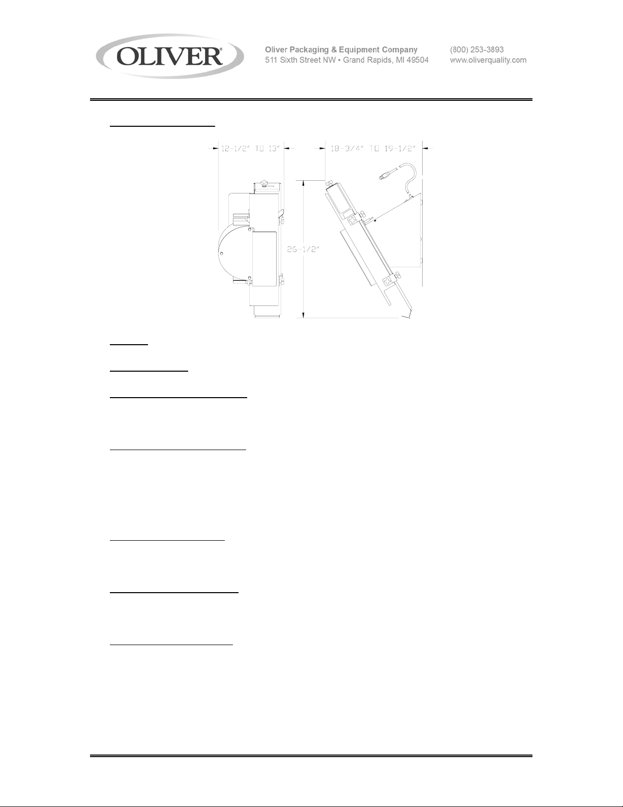
• Machine dimensions:
Model 702SS
• Weight:
Approximately (70) pounds.
• Standard Color:
Gloss white enamel.
• Standard Electrical Service:
1/3 HP, 1725 RPM, 1-60-115 Volts AC, 6 Amps.
• Optional Electrical Services
:
1/3 HP, 1725 RPM, 1-60-230 Volts AC, 3.5 Amps.
1/3 HP, 1425 RPM, 1-50-220 Volts AC, 3.5 Amps.
PRODUCT CAPACITIES
• Maximum Product Size
:
4-7/8 inches Wide and 3 inches High
• Blade Height (adjustable):
5/8 inch to 1-1/2 inches
• Maximum Cutting Depth:
4-3/8 inches
REV. 8-28-96 0702S20019-2
Page 5

MODEL 702, 702SE and 702SS BUN SLICERS
SAFETY INSTRUCTIONS
Every effort has been made by Oliver Products Company to provide you with a safe
machine. It is essential, however, that machine operators and maintenance personnel
observe the following safety precautions.
1. Before attempting to operate your slicer read this manual. Never allow an untrained
person to operate this machine.
2. Make sure that the machine is only connected to a properly grounded electrical
supply source of sufficient capacity for the load the slicer will put on it. Always
unplug the machine when it is not in use.
3. Always make sure the machine has been disconnected from the power supply
before cleaning or servicing.
4. Never stick your hand or any other objects into either end of the chute. Keep your
hands away from the moving parts of the machine.
5. Never attempt to adjust or service this machine until your are SURE
the blade has
stopped.
6. Always make sure the knife is not rubbing or hitting any metal components before restarting the machine.
7. All guards must be in place before starting the machine.
8. Handle knife blades with care. Do not touch the moving knife.
9. Use only proper replacement parts.
10. In addition to these general safety instructions, also follow the more specific safety
instructions given for the different areas of the machine in the operating instructions.
REV. 8-28-96 0702S20020
Page 6
GENERAL
DEFINITIONS
The use of the words WARNING, CAUTION, and NOTE in this manual should be guided
by the following.
WARNING
AN OPERATING PROCEDURE, TECHNIQUE, ETC., WHICH MAY
RESULT IN PERSONAL INJURY IF NOT CAREFULLY FOLLOWED.
CAUTION
AN OPERATING PROCEDURE, TECHNIQUE, ETC., WHICH MAY
RESULT IN DAMAGE TO EQUIPMENT IF NOT CAREFULLY FOLLOWED.
NOTE
AN OPERATING PROCEDURE, TECHNIQUE, ETC., WHICH IS CONSIDERED
ESSENTIAL TO EMPHASIZE.
GEN931118
Page 7
MODEL 702, 702SE and 702SS BUN SLICERS
ADJUSTMENTS
WARNING
NEVER ATTEMPT TO ADJUST OR SERVICE THIS MACHINE UNTIL
YOU ARE SURE THE BLADE HAS STOPPED.
OUTSIDE SIDE GUIDE
This guide is used to determine the amount of "Hinge" left on the product and can be
adjusted from leaving approximately a 1/2" hinge to a complete sever.
The guide is adjusted by loosening the two knobs which are below and to the outside of
the table and by sliding the guide in or out to generate the desired amount of hinge. Retighten the knobs when the guide is in the desired location.
CAUTION
MAKE SURE THAT THE BLADE IS NOT HITTING ANY OF THE OTHER
COMPONENTS BEFORE RE-STARTING THE MACHINE.
TABLE HEIGHT ADJUSTMENT
The table can be adjusted so that the height of the blade above the table is between 5/8"
and 1-1/2".
To change the height of the blade loosen the large knob on the front corner of the
machine's base below the table. Once loosened the thumb screw below the table can
be rotated clockwise to increase the table height (decrease bottom slice thickness),
or rotated counter clockwise to decrease table height, (increase bottom slice thickness).
Once the desired slice thickness is achieved re-tighten the large knob on the corner of
the base to secure the table in the new position.
CAUTION
MAKE SURE THAT THE BLADE IS NOT HITTING ANY OF THE OTHER
COMPONENTS BEFORE RE-STARTING THE MACHINE.
INSIDE SIDE GUIDE
Generally it is best to leave the inside guide adjusted to the maximum opening, this will
allow the product to pass through uninhibited for maximum slicing speed. However,
some products will require its use to reduce jamming.
(continued on next page)
REV. 8-28-96 0702S20022-1
Page 8
MODEL 702, 702SE and 702SS BUN SLICERS
If it seems necessary to adjust this guide loosen the two knobs which are on the top and
to the inside of the table, then slide the guide in or out to conform with product width.
Make a liberal adjustment to allow for product variances. Re-tighten the knobs to secure
it in the desired position.
SLOW-DOWN DOOR ADJUSTMENT (Model 702 only)
On the discharge end of the chute you will find a small adjustable door used to slow the
product as it exits the blade. Generally heavier products require a lower door setting
while lighter products require less restriction. The door is raised by turning the thumb
screw in a clockwise direction. Turning the screw in the opposite direction will lower the
door.
Normally if a bun should stop beneath the door the next bun should dislodge it, if it does
not then the door should be adjusted to provide less restriction.
WARNING
NEVER STICK YOUR HAND OR ANY OTHER OBJECT INTO EITHER
END OF THE CHUTE. ALWAYS KEEP YOUR HANDS AWAY FROM
THE MOVING PARTS OF THE MACHINE.
REV. 8-28-96 0702S20022-2
Page 9

MODEL 702, 702SE and 702SS BUN SLICERS
OPERATING INSTRUCTIONS
After adjustments for product width and bottom slice height have been made, (see
adjustment section), you are ready to begin slicing your product.
Start the motor by turning the switch to the "ON" position, then place the product on the
chute and allow it to slide into the blade, (do not throw the product into the machine). If
the buns resist sliding freely into the blade simply use one or more additional buns to
advance the first into slicing position.
WARNING
NEVER STICK YOUR HAND OR ANY OTHER OBJECT INTO EITHER
END OF THE CHUTE. KEEP YOUR HANDS AWAY FROM THE MOVING
PARTS OF THE MACHINE.
On Model 702 machines, should the sliced bun stop under the discharge door, the next
bun through the blade will generally dislodge it. If this does not happen, re-adjust the
slow down door or inside guide, see adjustment section of this manual.
REV. 8-28-96 0702S20023
Page 10

MODEL 702, 702SE and 702SS BUN SLICERS
MAINTENANCE/CLEANING/LUBRICATION
WARNING
NEVER ATTEMPT TO CLEAN OR SERVICE THIS MACHINE UNTIL IT
HAS BEEN DISCONNECTED FROM THE POWER SUPPLY AND YOU
ARE SURE THE BLADE HAS STOPPED. ALSO REMEMBER TO USE
CARE WHENEVER YOU ARE WORKING NEAR THE BLADE.
MAINTENANCE
Other than normal cleaning and occasional blade replacement little other regular
maintenance is required.
CLEANING
Use a mild detergent solution or spray cleaner on all exterior and interior surfaces as
necessary. Periodically remove the overhead guard assembly and blade guard, then
brush, or vacuum, all foreign material from below the chute and from the blade
compartment.
• Remove the blade guard by removing the three hex head screws which hold it in
place. Lift it clear of the machine and set it one side.
• Remove the outside side guide and chute guard assembly by
completely removing both knobs which secure it in place.
The blade will need to be removed and cleaned occasionally due to product build up,
especially when cutting fruity or sticky breads. See “Changing the Blade” latter in this
manual for instruction on how to remove the blade
.
WARNING
ALWAYS USE CARE WHEN HANDLING AND CLEANING KNIVES.
LUBRICATION
No lubrication is required. The motor is equipped with pre-lubricated sealed bearings
which require NO lubrication, DO NOT
attempt to oil or grease the motor.
REV. 8-28-96 0702S20010
Page 11
MODEL 702, 702SE and 702SS BUN SLICERS
CHANGING THE BLADE
WARNING
NEVER ATTEMPT TO CLEAN OR SERVICE THIS MACHINE UNTIL
IT HAS BEEN DISCONNECTED FROM THE POWER SUPPLY AND
YOU ARE SURE THE BLADE HAS STOPPED. ALSO REMEMBER
TO USE CARE WHENEVER YOU ARE WORKING NEAR THE BLADE.
CHANGING THE BLADE
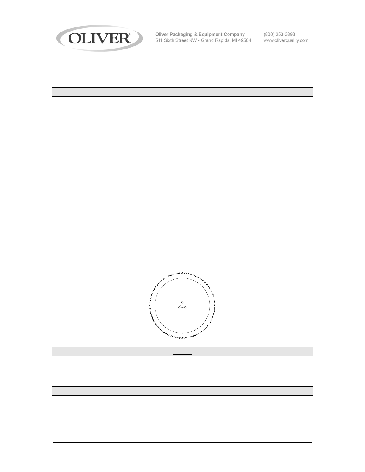
• Remove the overhead guard assembly by removing the three hex head screws
which hold it in place. Lift the assembly clear of the machine and set it one side.
• Remove the outside side guide and chute guard assembly by completely removing
both knobs which secure it in place.
• Using an "Allen" wrench remove the three screws securing the blade to the hub and
lift the blade from the machine.
• The blade can then be replaced by reversing the above procedure.
• When reinstalling the blade, make sure that the points on the teeth are pointed in a
counter clockwise direction.
NOTE
LOOKING AT THE SHAFT END OF THE MOTOR THE BLADE SHOULD
ALWAYS ROTATE CLOCKWISE.
WARNING
DO NOT START THE SLICER UNTIL ALL GUARDS ARE IN PLACE
AND SECURELY FASTENED AND YOU HAVE MADE SURE THAT
THE BLADE IS NOT HITTING ANY OF THE METAL PARTS.
REV. 8-28-96 0702S20028
Page 12

MODEL 702, 702SE and 702SS BUN SLICERS
TROUBLE SHOOTING
WARNING
NEVER ATTEMPT TO CLEAN OR SERVICE THIS MACHINE UNTIL
IT HAS BEEN DISCONNECTED FROM THE POWER SUPPLY AND
YOU ARE SURE THE BLADE HAS STOPPED.
THE SLICER MOTOR WILL NOT START.
• Check to see if the machine is plugged in.
• If plugged in, is the outlet working? Test it with another, working, small appliance.
• Your slicer's motor is equipped with a thermal overload. Should the motor become
overheated it will stop. To restart allow the motor to cool for approximately five
minutes, then reset the overload by pressing the red button on the case of the motor.
• If you still can not find the problem have a qualified electrician check the unit's motor
and switch.
THE SLICER’S MOTOR WAS RUNNING BUT SUDDENLY STOPPED.
• Check to see if the machine's plug was accidentally removed.
• Your slicer's motor is equipped with a thermal overload. Should the motor become
overheated it will stop. To restart allow the motor to cool for approximately five
minutes, then reset the overload by pressing the red button on the case of the motor.
• If you still can not find the problem have a qualified electrician check the unit's motor
and switch.
REV. 8-28-96 0702S20024
Page 13

MODEL 702, 702SE and 702SS BUN SLICERS
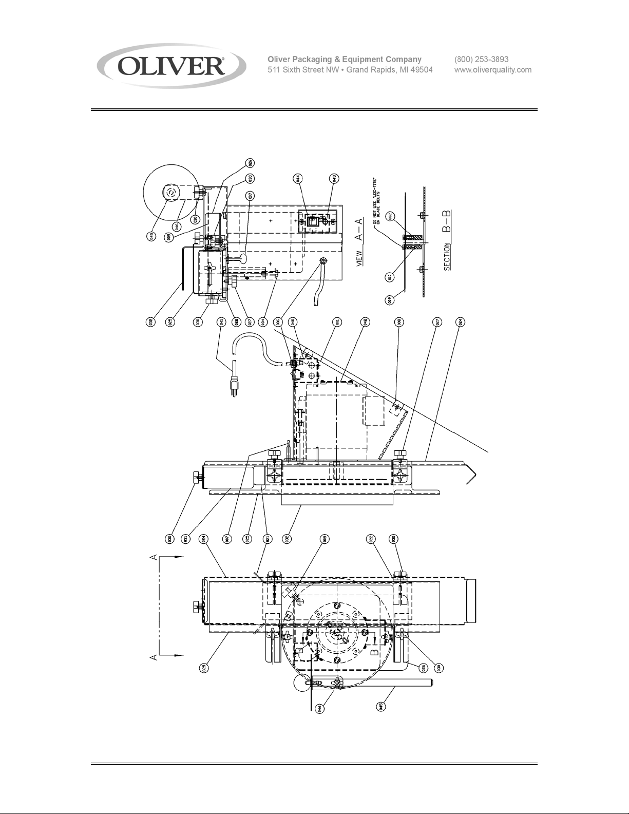
REPLACEMENT PARTS LIST
ITEM NO.
PART DESCRIPTION PART NUMBER
001 Frame 0702-0010-003
002 Adapter-Blade 0702-0025
003 Guard-Blade 0700-0003
005 Screw-Clamp 4560-2510-1104
006 Bushing-Strain Relief 5765-1071
007 Screw-Thumb 3/6-16 x 1-1/2 5843-0545
008 Foot-Rubber 5902-0011
009 Knife-Scalloped StSt 7107-7053
021 Guide-Outside (Model 702) 0700-0004
021 Guide-Outside (Model 702SE) 0702-0017
021 Guide-Outside (Model 702SS) 0702-0017-001
022 Bracket-Outside Guide (Model 702) 0702-0009
022 Bracket-Outside Guide (OTHERS) 0702-0018
024 Table (Model 702) 0700-0011
024 Table (Model 702SE) 0702-0016
024 Table (Model 702SS) 0702-0016-001
025 Guard-Overhead (Model 702) 0702-0001
025 Guard-Overhead (Model 702SE) 0702-0020
025 Guard-Overhead (Model 702SS) 0702-0020-001
026 Guide-Inside (Model 702) 0702-0002
026 Guide-Inside (Model 702SE) 0702-0019
026 Guide-Inside (Model 702SS) 0702-0019-001
027 Screw-Clamp 4560-2508-1106
028 Cap-Neoprene 5106-8920
029 Screw-Thumb 1/4-20 x 1-1/2 5843-0540
030 Knob-4 Prong 5911-7034
031 Stop-Bread 0702-0021
040 Cover-Switch & Light 0702-0008-002
041 Cord-Power 1-60-115 VAC 0709-0056-003
042 Motor 1/3 HP 1-50/60-115/230 6301-1641
043 Light-Pilot 115 VAC 5709-0021
043 Light-Pilot 230 VAC 5709-0012
044 Switch-Rocker 5757-3307
045 PUSHER – BAGEL 0702-0044
046 BRACKET – PUSHER 0702-0045
REV. 7/7/10 0702S20026
Page 14
MODEL 702, 702SE and 702SS BUN SLICERS
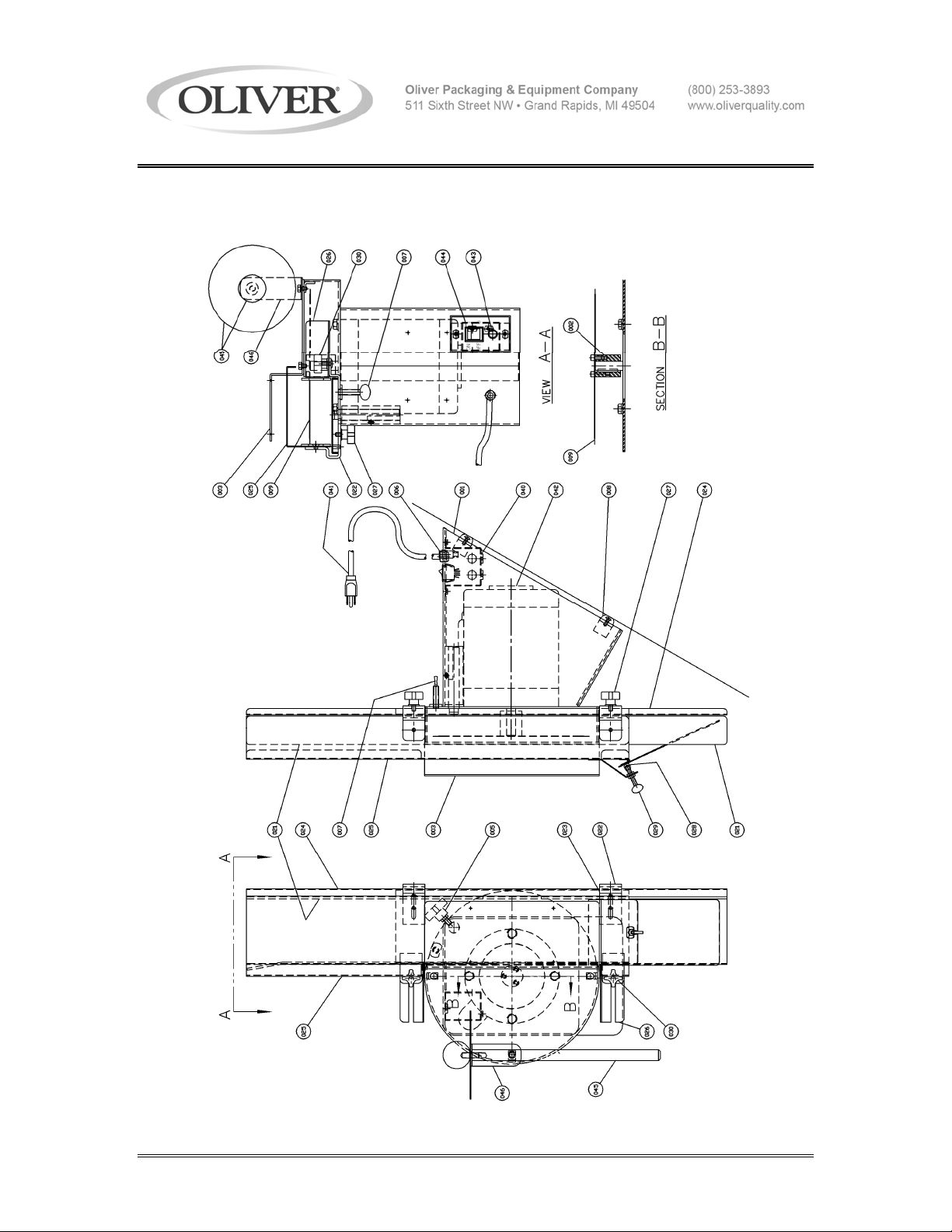
ASSEMBLY DRAWING MODEL 702
REV. 7/7/10 0702S20021
Page 15
MODEL 702, 702SE and 702SS BUN SLICERS
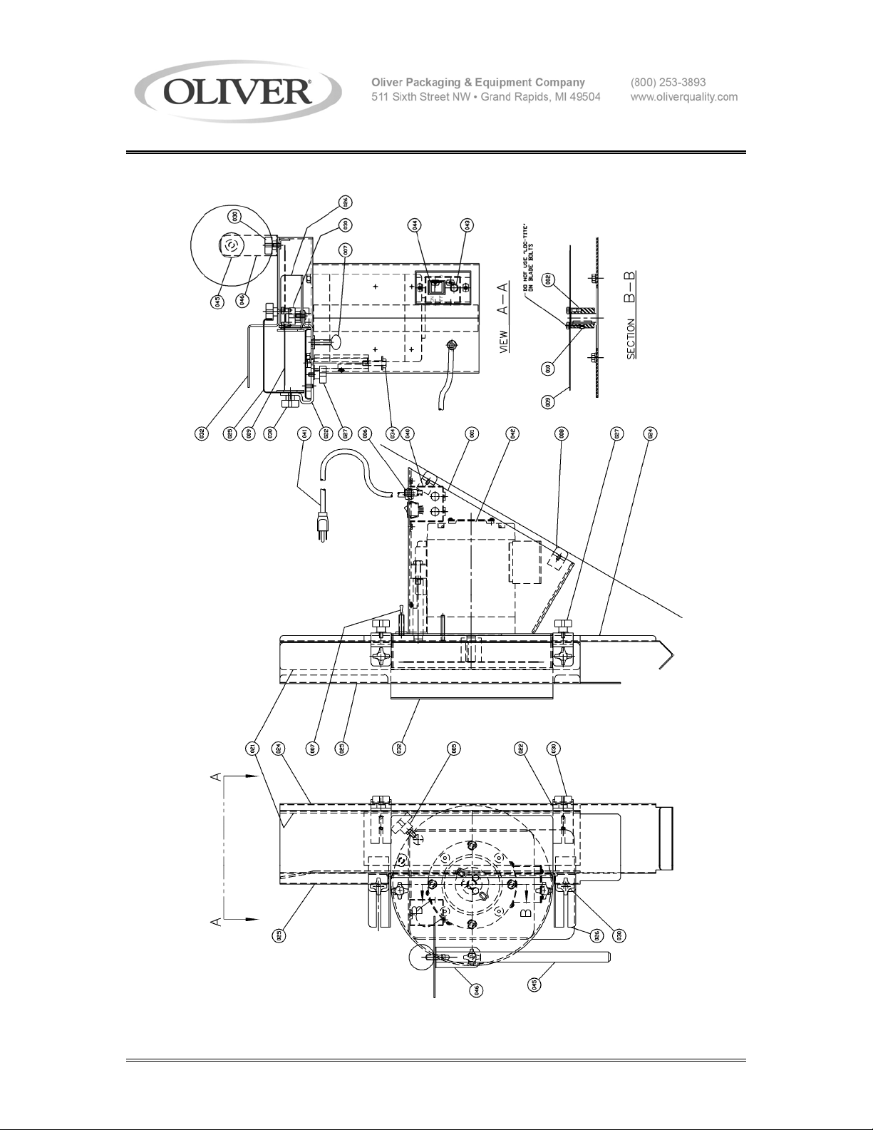
ASSEMBLY DRAWING MODEL 702SE
REV 7/7/10 0702S20029
Page 16
MODEL 702, 702SE and 702SS BUN SLICERS
ASSEMBLY DRAWING MODEL 702SS
REV 7/7/10 0702S20030
Page 17
MODEL 702, 702SE and 702SS BUN SLICERS
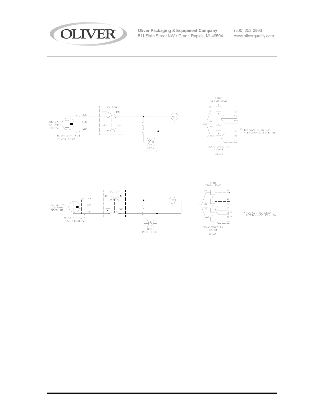
WIRING DIAGRAMS
Wiring Diagram (1/3 HP, 1Ph, 50/60 Hz, 115 VAC)
Diagram No. 0702C12007
Wiring Diagram (1/3 HP, 1Ph, 50/60 Hz, 230 VAC)
Diagram No. 0702C12008
0702S20025
Page 18

WARRANTY
PARTS
Oliver Packaging & Equipment Company (Oliver) warrants that if any part of the equipment (other
than a part not manufactured by Oliver) proves to be defective (as defined below) within one year
after shipment, and if Buyer returns the defective part to Oliver within one year, Freight Prepaid to
Oliver’s plant in Grand Rapids, MI, then Oliver, shall, at Oliver’s option, either repair or replace the
defective part, at Oliver’s expense.
LABOR
Oliver further warrants that equipment properly installed in accordance with our special instructions,
which proves to be defective in material or workmanship under normal use within one (1) year from
installation or one (1) year and three (3) months from actual shipment date, whichever date comes
first, will be repaired by Oliver or an Oliver Authorized Service Dealer, in accordance with Oliver’s
published Service Schedule.
For purposes of this warranty, a defective part or defective equipment is a part or equipment which is
found by Oliver to have been defective in materials workmanship, if the defect materially impairs the
value of the equipment to Buyer. Oliver has no obligation as to parts or components not
manufactured by Oliver, but Oliver assigns to Buyer any warranties made to Oliver by the
manufacturer thereof.
This warranty does not apply to:
1. Damage caused by shipping or accident.
2. Damage resulting from improper installation or alteration.
3. Equipment misused, abused, altered, not maintained on a regular basis, operated carelessly, or
used in abnormal conditions.
4. Equipment used in conjunction with products of other manufacturers unless such use is approved
by Oliver Products in writing.
5. Periodic maintenance of equipment, including but not limited to lubrication, replacement of wear
items, and other adjustments required due to installation, set up, or normal wear.
6. Losses or damage resulting from malfunction.
The foregoing warranty is in lieu of all other warranties expressed or implied AND OLIVER MAKES
NO WARRANTY OF MERCHANTABILITY OR FITNESS FOR PURPOSE REGARDING THE
EQUIPMENT COVERED BY THIS WARRANTY. Oliver neither assumes nor authorizes any person
to assume for it any other obligations or liability in connection with said equipment. OLIVER SHALL
NOT BE LIABLE FOR LOSS OF TIME, INCONVENIENCE, COMMERCIAL LOSS, INCIDENTAL OR
CONSEQUENTIAL DAMAGES.
GEN 040225
Page 19

WARRANTY PROCEDURE
1. If a problem should occur, either the dealer or the end user must contact the Parts and
Service Department and explain the problem.
2. The Parts and Service Manager will determine if the warranty will apply to this particular
problem.
3. If the Parts and Service Manager approves, a Work Authorization Number will be
generated, and the appropriate service agency will perform the service.
4. The service dealer will then complete an invoice and send it to the Parts and Service
Department at Oliver Products Company.
5. The Parts and Service Manager of Oliver Packaging and Equipment Company will
review the invoice and returned parts, if applicable, and approve for payment.
GEN 040226
Page 20

RETURNED PARTS POLICY
This policy applies to all parts returned to the factory whether for warranted credit,
replacement, repair or re-stocking.
Oliver Packaging and Equipment Company requires that the customer obtain a Return
Material Authorization (RMA) number before returning any part. This number should appear
on the shipping label and inside the shipping carton as well. All parts are to be returned
prepaid. Following this procedure will insure prompt handling of all returned parts.
To obtain an RMA number contact the Repair Parts Deptartment toll free at (800) 253-3893.
Parts returned for re-stocking are subject to a RE-STOCKING CHARGE.
Thank you for your cooperation,
Repair Parts Manager
Oliver Packaging and Equipment Company
GEN 040227
 Loading...