

Page 1

Grand Rapids, Michigan, U.S.A. 49504-5298
USER’S OPERATING AND INSTRUCTION MANUAL
MODEL 738
MINI CHIP SLICER
0738S20000-CV
Page 2

INDEX
Section Description
Document No. Page No.
SAFETY INSTRUCTIONS -------------------------------------- 0738S20002 --------------------------- 1-1
DESCRIPTION/SPECIFICATIONS --------------------------- 0738S20016---------------------------- 2-1
INSTALLATION INSTRUCTIONS ---------------------------- 0738S20004 --------------------------- 3-1
OPERATING INSTRUCTIONS -------------------------------- 0738S20017 --------------------------- 4-1
TROUBLESHOOTING ------------------------------------------- 0758S20006 --------------------------- 5-1
CLEANING AND MAINTENANCE -----------------------------0758S20018 --------------------------- 6-1
Removing the Blade Cartridge------------------------------------------------------------------------- 6-1
Cleaning ---------------------------------------------------------------------------------------------------- 6-4
Replacing the Blade Frames --------------------------------------------------------------------------- 6-5
Changing the Blades ------------------------------------------------------------------------------------- 6-7
Lubrication ------------------------------------------------------------------------------------------------- 6-8
General Cleaning ------------------------------------------------------------------------------------------ 6-8
REPLACEMENT PARTS SECTION
MAIN FRAME ------------------------------------------------------ 0758S20019 --------------------------- 7-1
Drawing ------------------------------------------------------------------------------------------------- 7-2
ELECTRICAL--------------------------------------------------------0758S20020 --------------------------- 8-1
Drawing ------------------------------------------------------------------------------------------------- 8-1
Parts List ------------------------------------------------------------------------------------------------8-2
DRIVE COMPONENTS-------------------------------------------0758S20021 --------------------------- 9-1
SLICE PARTS/COVERS -----------------------------------------0758S20022---------------------------10-1
Drawing ----------------------------------------------------------------------------------------------- 10-1
Parts List ---------------------------------------------------------------------------------------------- 10-2
WIRING DIAGRAM 1-60-120----------------------------------- 0738S20013 -------------------------- 12-1
WARRANTY ------------------------------------------------------- GEN 040225
WARRANTY PROCEDURE------------------------------------ GEN 040226
RETURNED PARTS POLICY --------------------------------- GEN 040227
0738S20015 0-1
Page 3

THIS PAGE WAS INTENTIONALLY
LEFT BLANK.
GEN020319
Page 4

SAFETY INSTRUCTIONS
WARNING
VARIOUS SAFETY DEVICES AND METHODS OF GUARDING HAVE BEEN
PROVIDED ON THIS MACHINE. IT IS ESSENTIAL HOWEVER THAT THE MACHINE
OPERATORS AND MAINTENANCE PERSONNEL OBSERVE THE FOLLOWING
SAFETY PRECAUTIONS. IMPROPER INSTALLATION, MAINTENANCE, OR
OPERATION OF THIS EQUIPMENT COULD CAUSE SERIOUS INJURY OR DEATH.
1. Read this manual before attempting to operate your machine. Never allow an
untrained person to operate or service this machine.
2. Connect the machine to a properly grounded electrical supply that matches the
requirements shown on the electrical specification plate and follow all specifications
of local electrical codes.
3. Disconnect and lock-out the machine from the power supply before cleaning or
servicing.
4. Check and secure all guards before starting the machine.
5. Observe all caution and warning labels affixed to the machine.
6. Use only proper replacement parts.
7. Do not wear loose fitting clothing or loose hair when working near this machine.
Shirt tails should be tucked in.
8. Wear proper, personal, protective, safety equipment.
9. Keep Hands away from the moving parts of this machine while it is in operation.
10. In addition to these general safety instructions, please follow the more specific safety
instructions as specified in the operating instruction manual.
11. The on/off switch is marked with international symbols for on and off. See below.
ON OFF
0738S20002 1-1
Page 5
DESCRIPTION/SPECIFICATIONS
Description
The Model 738 Mini Chip Slicer is a compact, countertop slicer designed to reprocess
shrink - specifically bagels and baguettes - into a marketable bakery/foodservice
product. Designed with reciprocating blade technology, the Mini Chip Slicer easily slices
through day-old bagels and baguettes.
The Model 738 Mini Chip Slicer is constructed of stainless and painted steel. Easy to
clean, the Mini Chip Slicer food contact surfaces - infeed cover, pusher, handle, and
blade cartridge - can be removed without the use of tools for cleaning and sanitizing in a
dishwasher. Blade changes are simple: simply remove the blade cartridge, replacing it
with an OEM cartridge. No tools or service company required.
Specifications
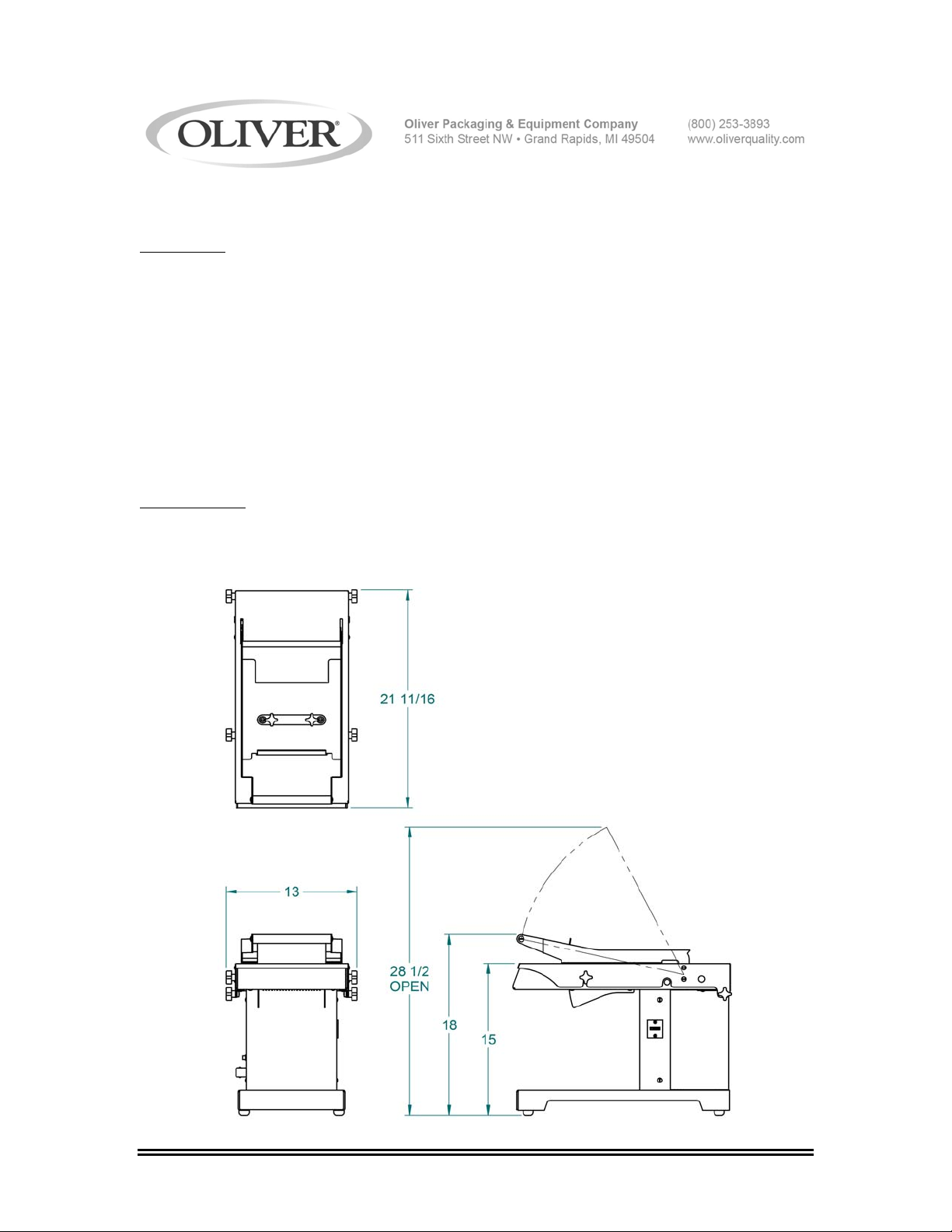
Space Requirements:
Model 738 (All Dimensions are Approximate)
0738S20016 2-1
Page 6

Product Capacities:
Length 6 inches
Width 6 inches
Height 2 inches
Standard Electrical Options: (Others consult factory)
1 phase, 60 Hz, 120VAC, 2 Amps.
Shipping Weight:
100 lbs. (approximate)
Net Weight:
80 lbs. (approximate)
0738S20016 2-2
Page 7

INSTALLATION INSTRUCTIONS
Before starting the Installation process make sure you observe the following caution
notes.
CAUTION
THE SLICER IS HEAVY, USE PROPER TECHNIQUE WHEN LIFTING OR MOVING.
Select a location for your slicer which has a substantial mounting surface and which has
electrical service compatible with the load the machine will place on it as indicated on
the electrical data plate of the machine. Position the machine while it is still in its
packaging as close as possible to the desired end location.
0738S20004 3-1
Page 8
OPERATING INSTRUCTIONS
WARNING
ALWAYS USE CARE WHENEVER WORKING NEAR THE CUTTING KNIVES.
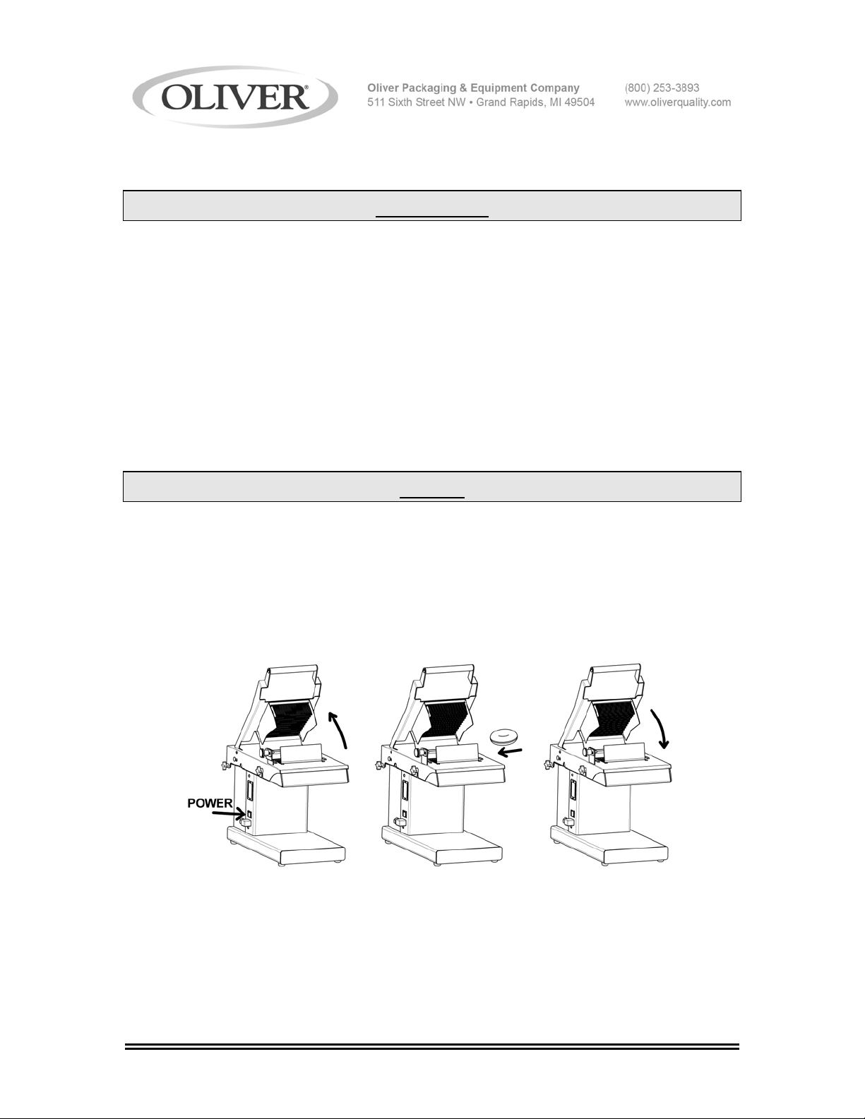
To operate the slicer, follow these simple steps:
1. Power unit on and lift the handle. The unit will automatically shut off.
2. Place the product atop the blades towards the front of the cutting area.
3. Using the handle, apply slight pressure in a downward motion until the handle
comes to a stop. Repeat steps 1-3.
4. When finished, power the unit off.
NOTE
THE UNIT WILL CONTIUE TO RUN UNLESS THE HANDLE IS LIFTED TO THE
STARTING POSITION. PLEASE REMEMBER TO POWER OFF THE UNIT WHEN
SLICING IS COMPLETE.
STEP 1 STEP 2 STEP 3
0738S20017 4-1
Page 9

THIS PAGE WAS INTENTIONALLY
LEFT BLANK.
GEN020319
Page 10

TROUBLE SHOOTING
WARNING
ALWAYS DISCONNECT THE SLICER FROM THE POWER SUPPLY BEFORE
ATTEMPTING ANY TYPE OF MAINTENANCE TASK, INCLUDING
TROUBLESHOOTING.
Slicer will not start
• The machine is not plugged in.
• There is no power at the outlet.
• The cover is not on correctly. The cover has an interlocking mechanism that
allows the unit to operate only if the cover is on.
• Broken wire or disconnected terminals.
• The switch actuator cam is not contacting the switch. Lift the cover and adjust
the screw with a flat head screw driver.
Pusher interference when slicing product
• Loosen pusher and adjust side to side to make sure there is no interference.
• Blade frame is not correctly placed on slide blocks.
• Pusher blades are bent or damaged. Contact dealer or factory.
Extreme effort needed to slice product
• Blades are dull. Contact dealer or factory for replacements.
• Product is too stale or old. The slicer is designed to be most efficient with slicing
fresh or day old product.
0738S20006 5-1
Page 11
CLEANING AND MAINTENANCE
WARNING
ALWAYS UNPLUG THE SLICER BEFORE PERFORMING
ANY TYPE OF MAINTENANCE TASK.
To prepare your unit for cleaning please refer to the pictorial below for step by step
instructions.
REMOVING THE BLADE CARTRIDGE
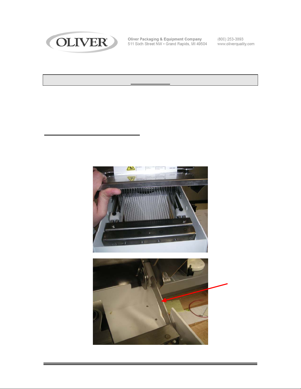
1. Loosen the (2) two thumb screws on the outside of the machine, tip the cover
assembly back as shown in figure A. Lift the cover props on each side of the
frame securely hold the cover open as shown in figure B.
Figure A
Figure B
0738S20018 6-1
Page 12
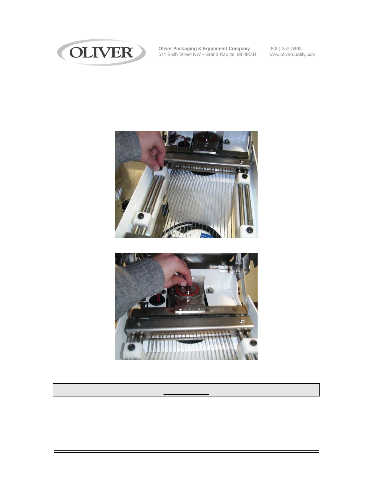
2. Loosen and remove the (4) thumbscrews atop the post hold down blocks (Fig. A)
and adjust the drive assembly so that the blade frame cartridge is in the closed
position as shown below (Fig. B). This is done by turning the knob on the drive
assembly so that the channels on the blade frames are close together.
NOTE: The protective blade cover will only fit on the cartridge when it is in the closed
configuration. This helps with the cleaning and re-assembly processes.
Figure A
Figure B
CAUTION
USE CAUTION WHILE ADJUSTING THE DRIVE ASSEMBLY. THE BLADES ARE
EXPOSED AND VERY SHARP.
0738S20018 6-2
Page 13
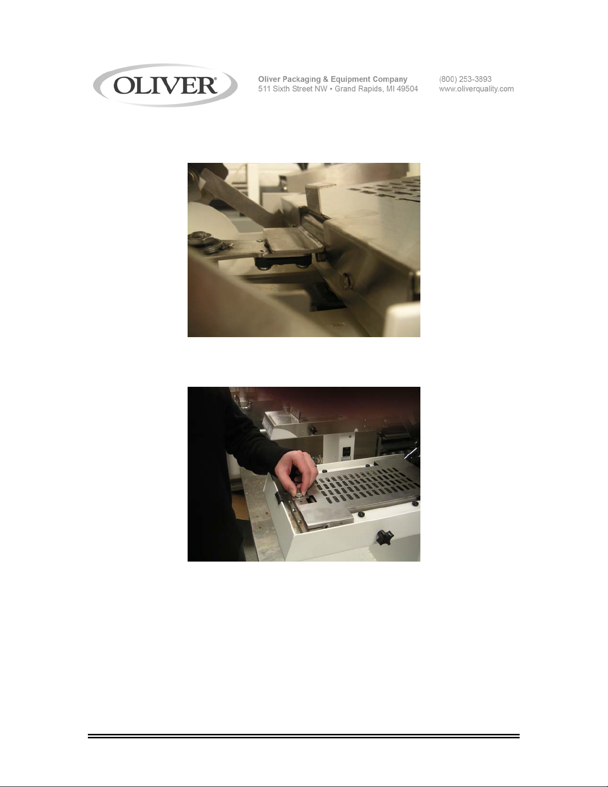
3. Place the protective blade cover atop the blade cartridge by hooking the cover
around the pin plate near the drive assembly.
4. Lay the cover down on top of the blade cartridge and fasten with the thumb
screw to the blade cartridge by threading the thumb screw into the hole provided.
0738S20018 6-3
Page 14
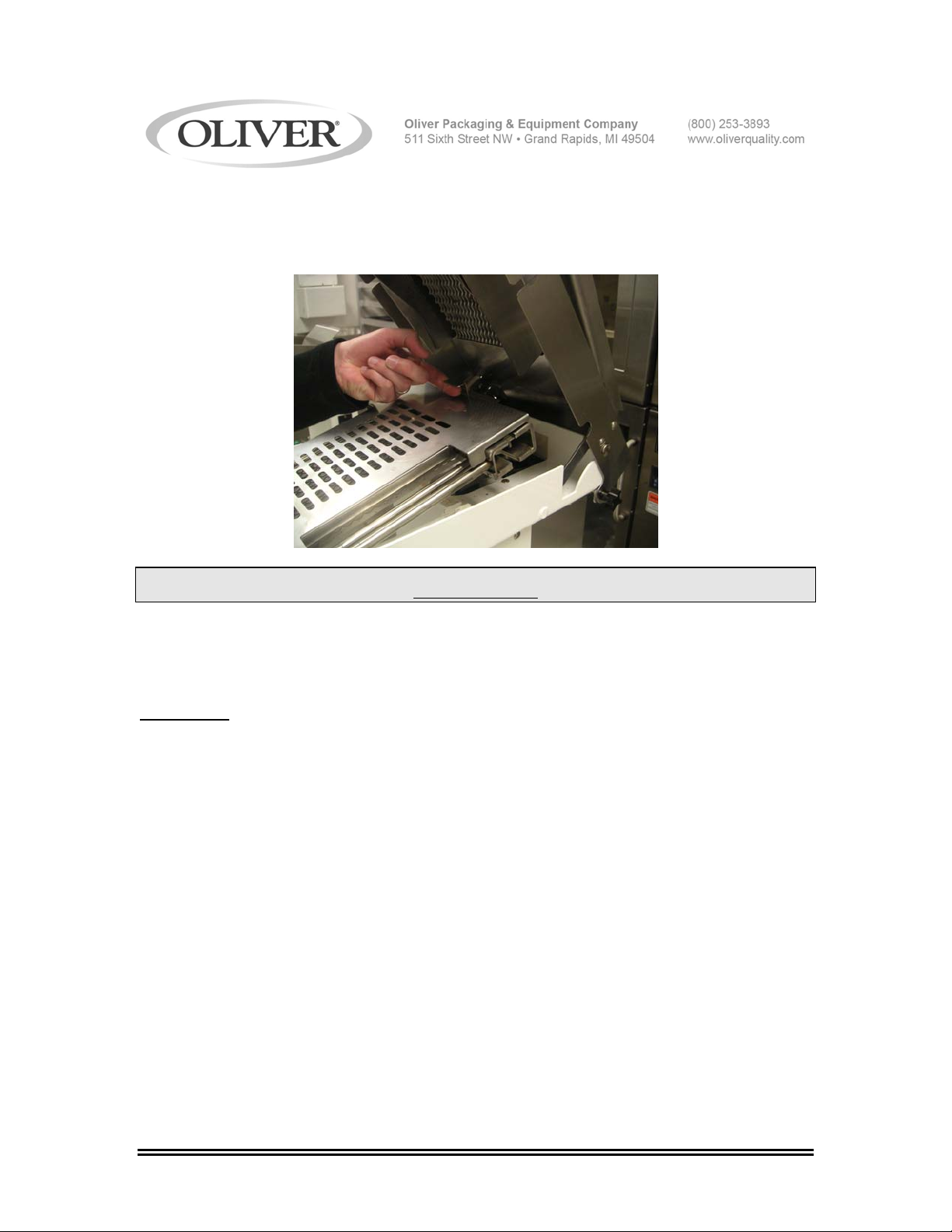
5. To remove the protected blade frame cartridge simply grip the front of the
assembly and the tab provided on the cover and pull up.
WARNING
NEVER REMOVE BLADE FRAME ASSEMBLY WITHOUT PROTECTIVE GUARD.
BLADES ARE EXTREMELY SHARP AND IF HANDLED INCORREC TLY MAY
RESULT IN SERIOUS INJURY.
CLEANING
Now that the blade frames have been safely removed you can now proceed with
removing any crumb deposits within the machine. A brush, compressed air, or a
vacuum are helpful tools for this task.
0738S20018 6-4
Page 15
REPLACING THE BLADE CARTRIDGE
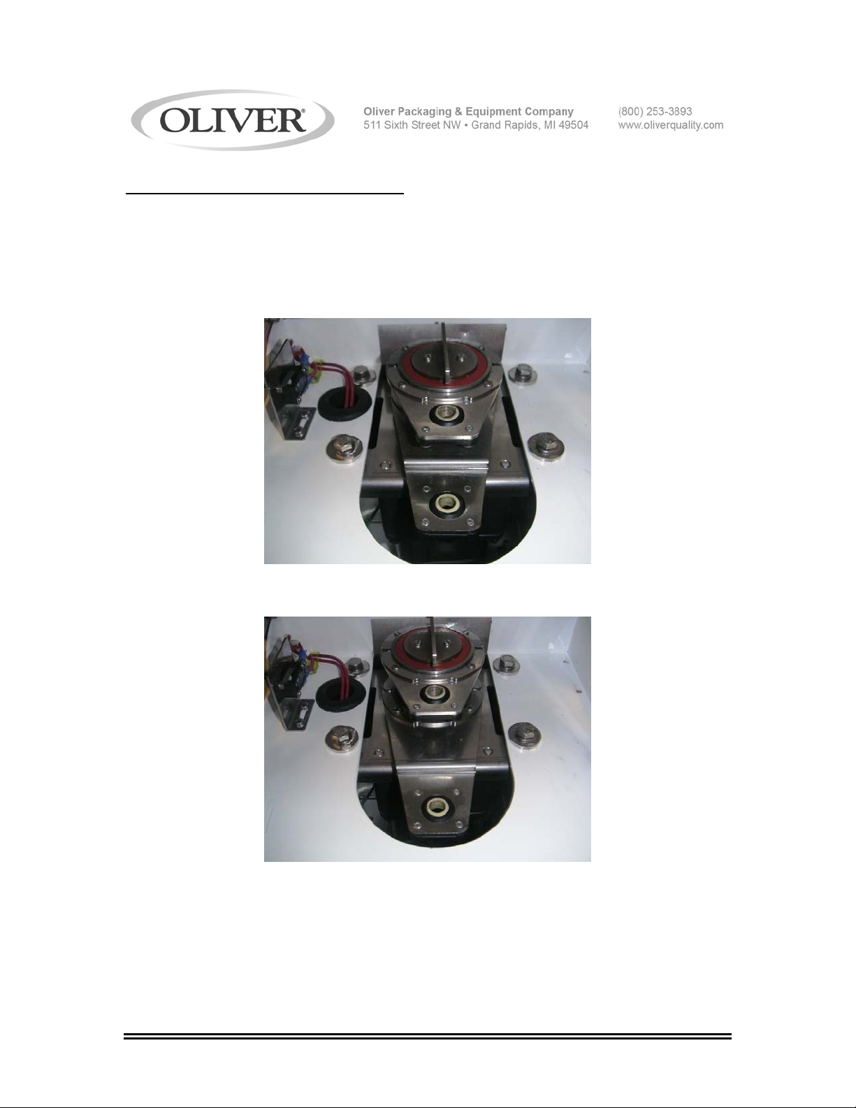
6. Make sure that the drive assembly is in the correct position as shown below.
NOTE: The blade cartridge will only fit back into the machine with the drive assembly in
the correct configuration below. The Bearing holes need to be at the position nearest
each other.
CORRECT
INCORRECT
0738S20018 6-5
Page 16
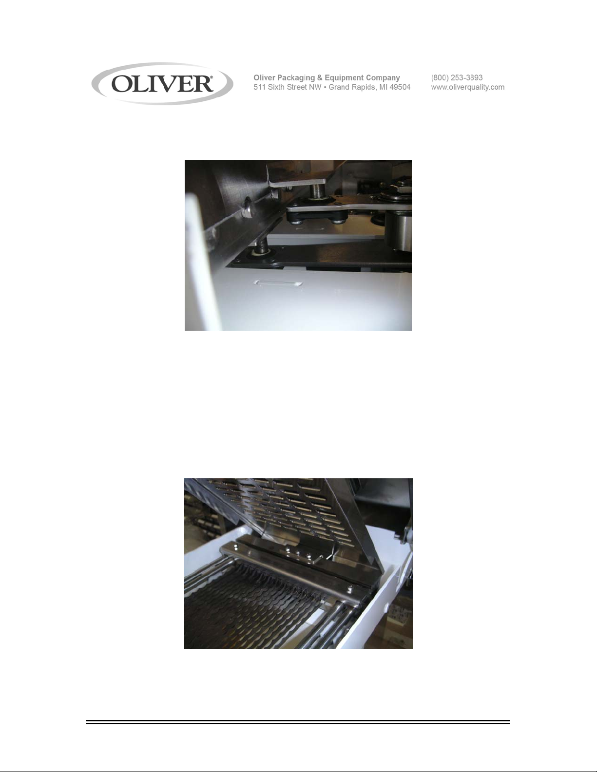
7. With the protective blade guard in place locate the center of the bearings in the
drive assembly with the pin plates attached to the blade cartridge.
8. Once the drive assembly has been located, place the blade cartridge posts in the
tracks on the base assembly. Apply slight pressure to the front and rear of the
blade cartridge to ensure the proper fit in to the drive assembly and slide blocks.
You can now replace the post hold down blocks that you set aside in step 5.
9. Remove the protective blade cover by loosening the thumb screw and unhooking
from the pin plate.
NOTE: The cover assembly will not fit on the unit if the protective blade cover is left in
place.
0738S20018 6-6
Page 17
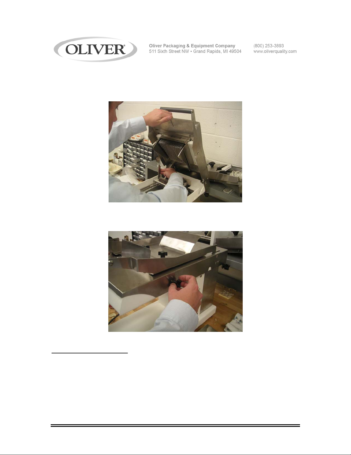
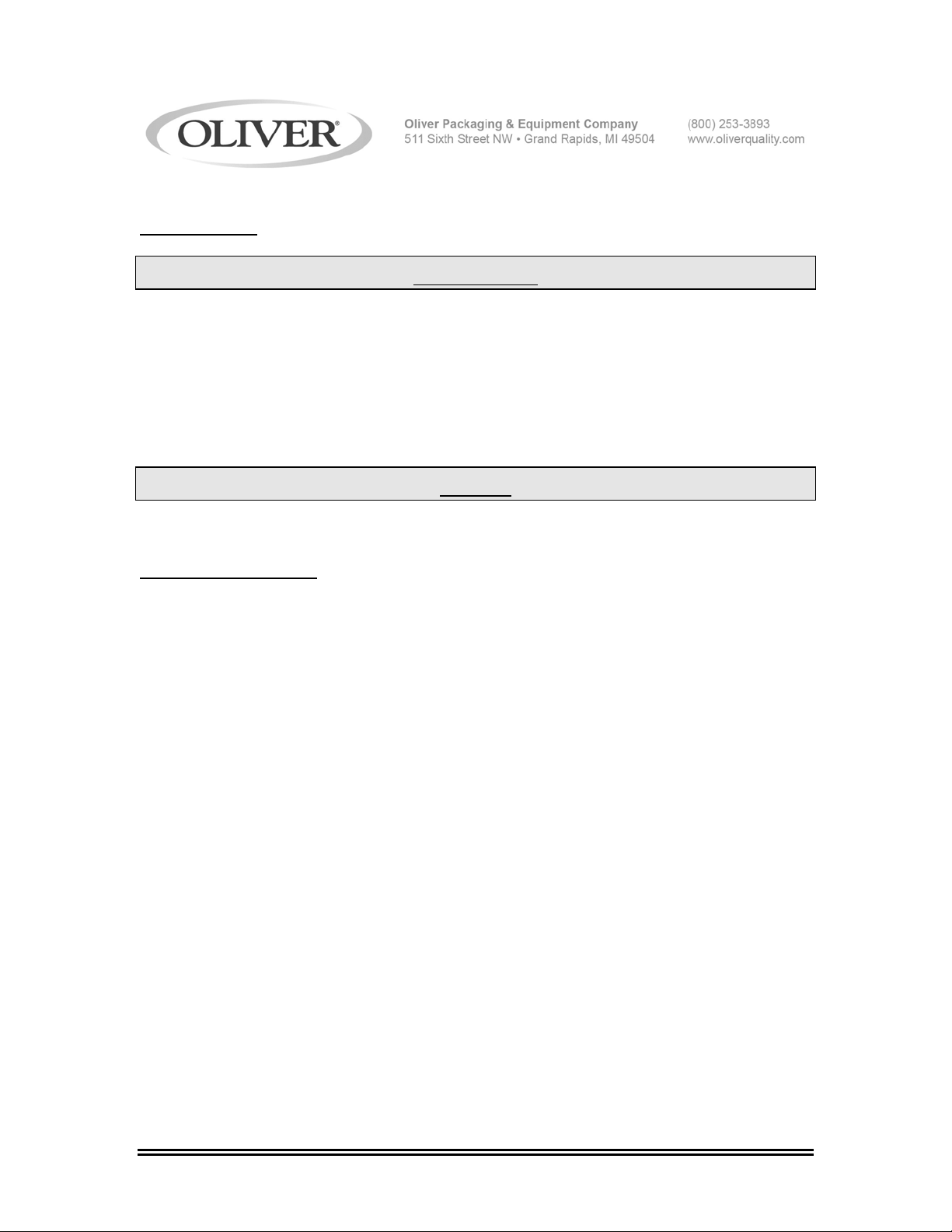
10. Lower the cover assembly by placing one hand on the front of the cover and
placing both of the cover props in their closed position. Gently lower the cover
assembly until it stops.
11. Lastly, after the cover has been lowered into position firmly tighten all thumb
screws around the perimeter of the unit.
CHANGING THE BLADES
Oliver Packaging and Equipment suggests that blades not be changed in the field due to
the potential for injury. We offer a blade frame cartridge exchange program for when
blades become dull. Please contact your dealer or the Oliver service department.
0738S20018 6-7
Page 18
LUBRICATION
WARNING
ALWAYS DISCONNECT THE SLICER FROM THE POWER SUPPLY BEFORE
ATTEMPTING ANY TYPE OF MAINTENANCE TASK.
Oliver suggests a vegetable based aerosol product be used to gently coat the blades on
occasion. Once a month put a drop of a food approved lubricant on the plastic slide
blocks on the inside of the unit. This will increase the longevity of the internal parts of
your slicer.
NOTE
NEVER OIL OR GREASE THE MOTOR.
GENERAL CLEANING
Use a mild detergent solution to clean the exterior surfaces. Periodically remove all
covers and brush or blow, (if compressed air is available), all foreign material from all
surfaces, especially moving parts.
0738S20018 6-8
Page 19
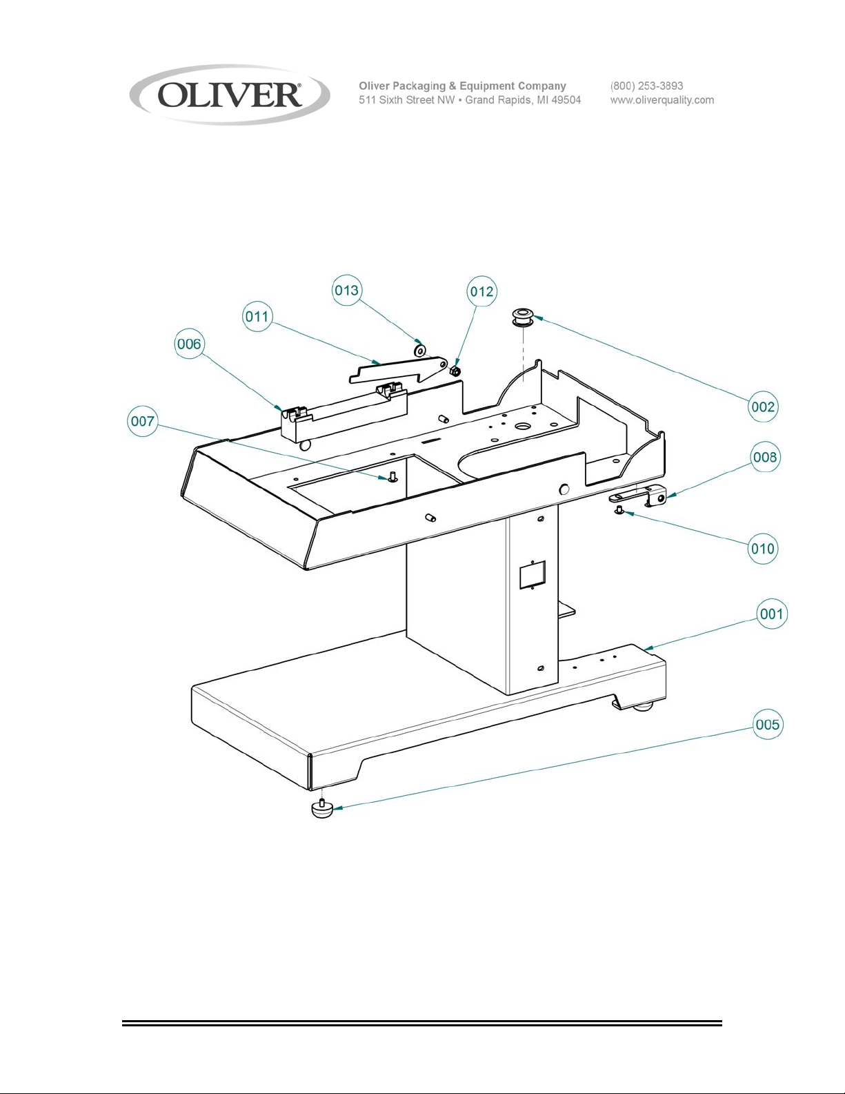
MAIN FRAME
0738S20019 7-1
Page 20

MAIN FRAME PARTS LIST
ITEM NO PART DESCRIPTION PART NUMBER
001 Base 0738-0002-1
002 Grommet-Rubber 5767-1207
003* Nut-10-24 Stainless Acorn 5832-0585
004* Washer-#10 Spring Lock Stainless 5851-9355
005 Bumper-Rubber w/ Screw 5902-0035
006 Block-Guide 0738-0003-1
007 Screw-10-24 x 3/8 Stainless Truss 5843-5384
008 Bracket-RH Cover Attachment 0738-0004-0001
009* Bracket-LH Cover Attachment 0738-0004-0002
010 Screw-10-24 x 1/4 Stainless Truss 5843-5383
011 Plate-Prop 0738-0005-1
012 Nut-1/4-20 Stainless Locking 5831-9087
013 Washer-1/4 Flat Stainless 5851-9304
*Items not shown
FOR SERVICE PARTS CALL OLIVER PACKAGING & EQUIPMENT @ 800-253-3893
0738S20019 7-2
Page 21
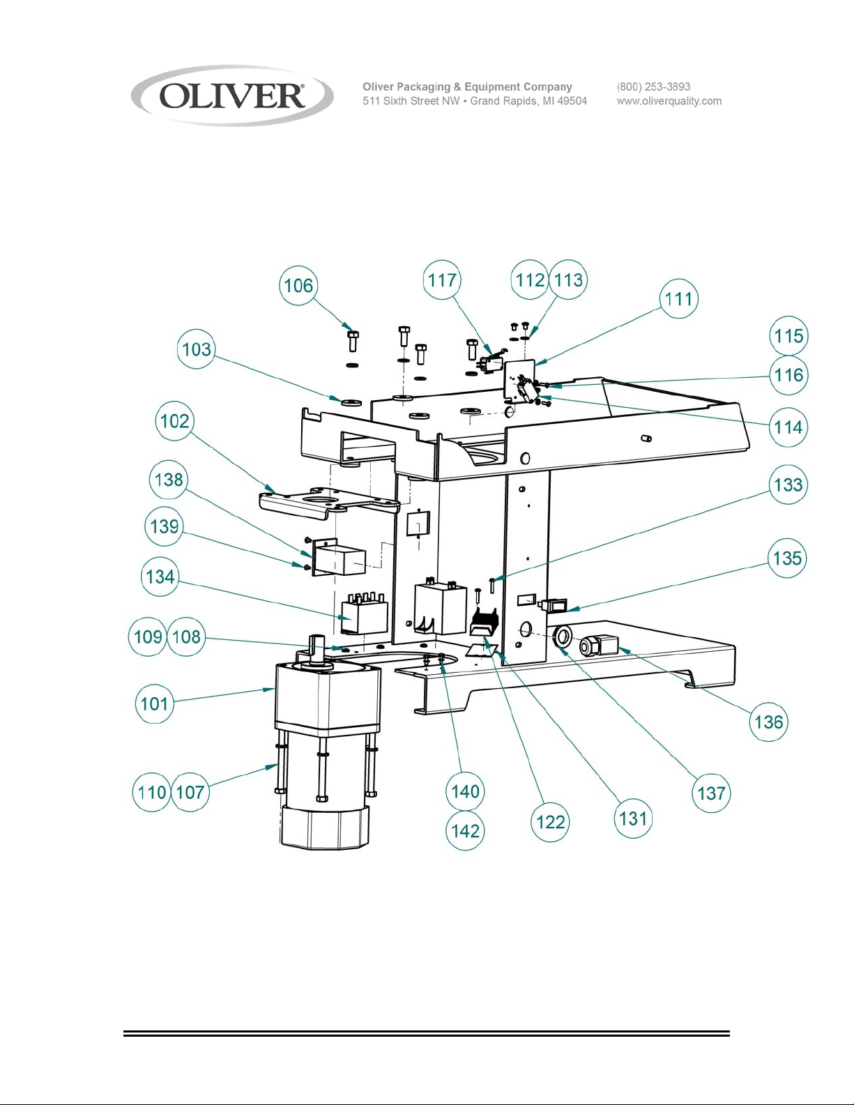
ELECTRICAL PARTS
0738S20020 8-1
Page 22

ELECTRICAL PARTS LIST
ITEM NO PART DESCRIPTION PART NUMBER
101 Assembly-Motor Cord 0738-25505K
102 Plate-Motor Mount 0738-0045
103 Spacer 0738-0046
106 Screw-5/16-18 x ¾ Stainless Hex 5843-1028
107 Screw-5/16-18 x 3 1/2 Stainless Hex 5843-1039
108 Screw-8-32 x 5/16 Stainless Pan 5843-5552
109 Washer-#8 Shake Proof Stainless 5851-9130
110 Washer-5/16 Lock Stainless 5851-9358
111 Mount-Switch 0738-0008
112 Screw-8-32 x ¼ Stainless Pan 5843-5551
113 Washer-#8 Flat Stainless 5851-8108
114 Switch-SM Basic w/ Roller 5757-8002
115 Screw-4-40 x 1/2 Stainless Pan 5843-5524
116 Washer-#4 Shake Proof Stainless 5851-9127
117 Switch-SM Basic 5757-8001
122 Block-Terminal 8 Row 5770-7451
131 Strip-Marker 8 Row 5770-7328
133 Screw-M3.5 x 16mm Stainless Pan 8843-2265
134 Relay 5749-8027
135 Switch-Rocker 5757-3314
136 Bushing-Strain Relief 90° 5765-1010
137 Nut-PG-11 Plastic Lock 5766-7786
138 Counter-5 Digit Mini 5712-9080
139 Screw-6-32 x 1/4 Stainless Truss 5843-5360
140 Screw-6-32 x 3/8 Green Grounding 5841-9501
142 Washer-#6 Shake Proof Stainless 5851-9129
FOR SERVICE PARTS CALL OLIVER PACKAGING & EQUIPMENT @ 800-253-3893
0738S20020 8-2
Page 23

THIS PAGE WAS INTENTIONALLY
LEFT BLANK.
GEN020319
Page 24
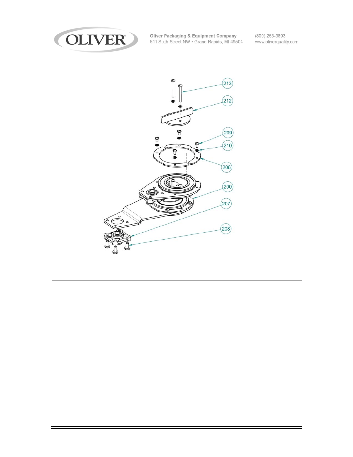
DRIVE COMPONENTS
DRIVE COMPONENTS PARTS LIST
ITEM NO PART DESCRIPTION PART NUMBER
200* Assembly-Drive 0738-25012K
206 Clip-Bearing 0738-0049
207 Bearing-10mm Spherical Flange Mount 5251-3591
208 Screw-10-24 x 3/8 Stainless Pan 5843-5384
209 Screw-6-32 x 1/4 Stainless Pan 5843-5541
210 Washer-#6 Lock Stainless 5851-9353
212 Knob 0738-0051
213 Screw-6-32 x 1 ¼ Stainless Pan 5843-5547
Replacements for 200 are ordered assembled with fasteners. Parts may not be
substituted within the assembly other than those called out.
FOR SERVICE PARTS CALL OLIVER PACKAGING & EQUIPMENT @ 800-253-3893
0738S20021 9-1
Page 25
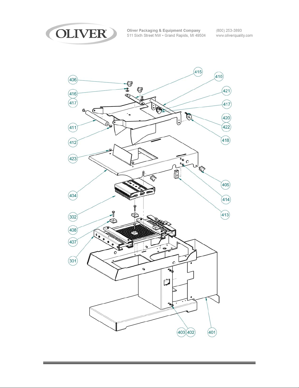
SLICE PARTS/COVERS
0738S20022 11-1
Page 26

SLICE PARTS/COVERS PARTS LIST
ITEM NO PART DESCRIPTION PART NUMBER
301 Cartridge-Blade Frame 0738-25XXXK
302 Assembly-Pusher 0738-25XXXK
303 Cover-Blade Frame Safety 0738-0024K
401 Cover-Motor 0738-0033-1
402 Screw-10-24 x 3/8 Stainless Truss 5843-5384
403 Washer-#10 Shake Proof Stainless 5851-9394
404 Cover-Base 0738-0034-1
405 Screw-Clamp 4560-2508-1106
406 Knob-1/4-20 4 Prong Plastic 5911-7034
407 Block-Top Guide 0738-0052
408 Screw-8-32 x 1 Stainless Thumb 0738-25504K
410 Assembly-Handle w/ Guard 0738-0038-1
411 Handle 0738-0039
412 Screw-1/4-20 x 1/2 Stainless Truss 5843-5412
413 Block-Handle Hinge 0738-0040
414 Screw-10-24 x 3/8 Stainless Truss 5843-5384
415 Plate-Pusher Centering 0738-0041
416 Screw-10-32 x 1/4 Stainless Truss 5843-5390
417 Washer-#10 Fender Stainless 5851-9324
418 Plate-RH Cover Cam 0738-0042-0001
419 Plate-LH Cover Cam 0738-0042-0002
420 Screw-8-32 x 1/4 Stainless Round 5843-5232
421 Screw-8-32 x 1/4 Stainless Tamper 5843-5650
422 Washer-#8 Spring Lock Stainless 5851-9354
423 Bumper-Press In 5902-0023
*Items 301 and 302 are replaced fully assembled. Specify slice thickness when
ordering.
**Item 303 is provided with each blade frame assembly and is used for safe handling.
Not Shown.
FOR SERVICE PARTS CALL OLIVER PACKAGING & EQUIPMENT @ 800-253-3893
0738S20022 11-2
Page 27
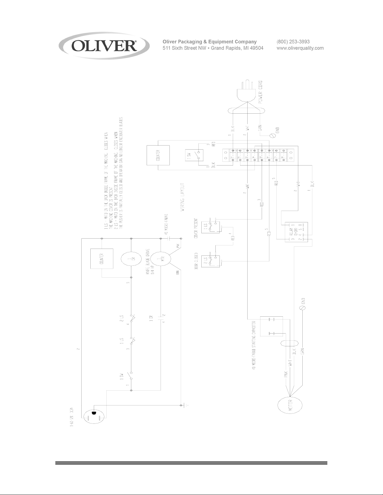
WIRING DIAGRAM 1-60-120
0738S20013 12-1
Page 28

WARRANTY
PARTS
Oliver Packaging & Equipment Company warrants that if any part of the equipment (other than a part
not manufactured by Oliver Packaging & Equipment ) proves to be defective (as defined below) within
one year after shipment, and if Buyer returns the defective part to Oliver Packaging & Equipment
within one year, Freight Prepaid to Oliver Packaging & Equipment plant in Grand Rapids, MI, then
Oliver Packaging & Equipment , shall, at Oliver Packaging & Equipment option, either repair or
replace the defective part, at Oliver Packaging & Equipment expense.
LABOR
Oliver further warrants that equipment properly installed in accordance with our special instructions,
which proves to be defective in material or workmanship under normal use within one (1) year from
installation or one (1) year and three (3) months from actual shipment date, whichever date comes
first, will be repaired by Oliver Packaging & Equipment or an Oliver Packaging & Equipment
Authorized Service Dealer, in accordance with Oliver Packaging & Equipment published Service
Schedule.
For purposes of this warranty, a defective part or defective equipment is a part or equipment which is
found by Oliver Packaging & Equipment to have been defective in materials workmanship, if the
defect materially impairs the value of the equipment to Buyer. Oliver Packaging & Equipment has no
obligation as to parts or components not manufactured by Oliver Packaging & Equipment, but Oliver
Packaging & Equipment assigns to Buyer any warranties made to Oliver Packaging & Equipment by
the manufacturer thereof.
This warranty does not apply to:
1. Damage caused by shipping or accident.
2. Damage resulting from improper installation or alteration.
3. Equipment misused, abused, altered, not maintained on a regular basis, operated carelessly, or
used in abnormal conditions.
4. Equipment used in conjunction with products of other manufacturers unless such use is approved
by Oliver Packaging & Equipment Company in writing.
5. Periodic maintenance of equipment, including but not limited to lubrication, replacement of wear
items, and other adjustments required due to installation, set up, or normal wear.
6. Losses or damage resulting from malfunction.
The foregoing warranty is in lieu of all other warranties expressed or implied AND OLIVER
PACKAGING & EQUIPMENT COMPANY MAKES NO WARRANTY OF MERCHANTABILITY OR
FITNESS FOR PURPOSE REGARDING THE EQUIPMENT COVERED BY THIS WARRANTY.
Oliver Packaging & Equipment Company neither assumes nor authorizes any person to assume for it
any other obligations or liability in connection with said equipment. OLIVER PACKAGING &
EQUIPMENT COMPANY SHALL NOT BE LIABLE FOR LOSS OF TIME, INCONVENIENCE,
COMMERCIAL LOSS, INCIDENTAL OR CONSEQUENTIAL DAMAGES.
GEN 040225
Page 29

WARRANTY PROCEDURE
1. If a problem should occur, either the dealer or the end user must contact the Parts and
Service Department and explain the problem.
2. The Parts and Service Manager will determine if the warranty will apply to this particular
problem.
3. If the Parts and Service Manager approves, a Work Authorization Number will be
generated, and the appropriate service agency will perform the service.
4. The service dealer will then complete an invoice and send it to the Parts and Service
Department at Oliver Packaging & Equipment Company.
5. The Parts and Service Manager of Oliver Packaging and Equipment Company will
review the invoice and returned parts, if applicable, and approve for payment.
GEN 040226
Page 30

RETURNED PARTS POLICY
This policy applies to all parts returned to the factory whether for warranted credit,
replacement, repair or re-stocking.
Oliver Packaging and Equipment Company requires that the customer obtain a Return
Material Authorization (RMA) number before returning any part. This number should appear
on the shipping label and inside the shipping carton as well. All parts are to be returned
prepaid. Following this procedure will insure prompt handling of all returned parts.
To obtain an RMA number contact the Repair Parts Deptartment toll free at (800) 253-3893.
Parts returned for re-stocking are subject to a RE-STOCKING CHARGE.
Thank you for your cooperation,
Repair Parts Manager
Oliver Packaging and Equipment Company
GEN 040227
 Loading...