

Page 1

Grand Rapids, Michigan, U.S.A. 49504-5298
USER’S OPERATING AND INSTRUCTION MANUAL
MODEL 641
DOUGH ROLLER
0641S20000-CV
Page 2

641 DOUGH ROLLER
INDEX
Section Description
Document No. Page No.
SAFETY INSTRUCTIONS -------------------------------------- 0641S20003 --------------------------- 1-1
DESCRIPTION/SPECIFICATIONS --------------------------- 0641S20004---------------------------- 2-1
Description -------------------------------------------------------------------------------------------------- 2-1
Specifications----------------------------------------------------------------------------------------------- 2-1
INSTALLATION INSTRUCTIONS ---------------------------- 0641S20005 --------------------------- 3-1
Dough Roller Installation ---------------------------------------------------------------------------------3-1
OPERATING INSTRUCTIONS -------------------------------- 0641S20006 --------------------------- 4-1
TROUBLESHOOTING ------------------------------------------- 0641S20007 --------------------------- 5-1
The Dough Roller Will Not Start (Motor is Not Humming) --------------------------------------- 5-1
The Dough Roller Will Not Start (Motor is Humming) -------------------------------------------- 5-1
Lines or Marks in Finished Crust ---------------------------------------------------------------------- 5-2
The Dough is Not Feeding ------------------------------------------------------------------------------ 5-2
The Dough is Sticking to Rollers -----------------------------------------------------------------------5-3
MAINTENANCE --------------------------------------------------- 0641S20008 --------------------------- 6-1
Cleaning ----------------------------------------------------------------------------------------------------- 6-1
Removing Scrapers -------------------------------------------------------------------------------------- 6-1
General Notes on Disassembly ----------------------------------------------------------------------- 6-2
Lubrication -------------------------------------------------------------------------------------------------- 6-2
Service ------------------------------------------------------------------------------------------------------- 6-2
RECOMMENDED SPARE PARTS -------------------------- 0641S20009 --------------------------- 7-1
REPLACEMENT PARTS SECTION
MAIN FRAME ------------------------------------------------------ 0641S2
Drawing ------------------------------------------------------------------------------------------------- 8-1
Parts List ----------------------------------------------------------------------------------------------- 8-2
ROLLERS ---------------------------------------------------------- 0641S20011 --------------------------- 9-1
Drawing ------------------------------------------------------------------------------------------------- 9-1
Parts List ----------------------------------------------------------------------------------------------- 9-2
TABLES ------------------------------------------------------------- 0641S20012 ---------------------------10-1
Drawing ----------------------------------------------------------------------------------------------- Parts List -----------------------------------------------------------------------------------------------10-2
COVERS ------------------------------------------------------------ 0641S20013 ---------------------------11-1
Drawing ----------------------------------------------------------------------------------------------- Parts List -----------------------------------------------------------------------------------------------11-2
0010 --------------------------- 8-1
10-1
11-1
Continued
0641S20002 0-1
Page 3

INDEX (Continued)
Section Description
Document No. Page No.
DRIVE --------------------------------------------------------------- 0641S20014 ---------------------------12-1
Drawing ----------------------------------------------------------------------------------------------- Parts List -----------------------------------------------------------------------------------------------12-2
ELECTRICAL PARTS ------------------------------------------- 0641S20015 ---------------------------13-1
Drawing ----------------------------------------------------------------------------------------------- Parts List -----------------------------------------------------------------------------------------------13-2
OPTIONAL STAND ---------------------------------------------- 0641S20016 ---------------------------14-1
Drawing ----------------------------------------------------------------------------------------------- Parts List -----------------------------------------------------------------------------------------------14-2
WIRING DIAGRAMS -------------------------------------------- 0641S20017 ---------------------------15-1
WARRANTY ---------------------------------------------------- --- GEN 040225
WARRANTY PROCEDURE------------------------------------ GEN 040226
RETURNED PARTS POLICY --------------------------------- GEN 040227
12-1
13-1
14-1
0641S20002 0-2
Page 4

641 DOUGH ROLLER
SAFETY INSTRUCTIONS
WARNING
VARIOUS SAFETY DEVICES AND METHODS OF GUARDING HAVE BEEN
PROVIDED ON THIS MACHINE. IT IS ESSENTIAL HOWEVER THAT THE MACHINE
OPERATORS AND MAINTENANCE PERSONNEL OBSERVE THE FOLLOWING
SAFETY PRECAUTIONS. IMPROPER INSTALLATION, MAINTENANCE, OR
OPERATION OF THIS EQUIPMENT COULD CAUSE SERIOUS INJURY OR DEATH.
1. Read this manual before attempting to operate your machine. Never allow an
untrained person to operate or service this machine.
2. Connect the machine to a properly grounded electrical supply that matches the
requirements shown on the electrical specification plate and follow all specifications
of local electrical codes.
3. Disconnect and lock-out the machine from the power supply before cleaning or
servicing.
4. Check and secure all guards before starting the machine.
5. Observe all caution and warning labels affixed to the machine.
6. Use only proper replacement parts.
7. Do not wear loose fitting clothing or loose hair when working near this machine.
Shirt tails should be tucked in.
8. Wear proper, personal, protective, safety equipment.
9. Keep Hands away from the moving parts of this machine while it is in operation.
10. In addition to these general safety instructions, please follow the more specific safety
instructions in the rest of this operating instruction manual.
WARNING
DO NOT USE FOR OTHER THAN ORIGINALLY INTENDED PURPOSE.
0641S20003 1-1
Page 5
641 DOUGH ROLLER
DESCRIPTION/SPECIFICATIONS
Description
The Oliver Model 641 Dough Roller is engineered to exacting standards. It’s designed to
provide maximum performance in minimal space. The machine is easy to operate, crusts
of uniform thickness are made quickly and easily.
Parts to be cleaned are quickly removed without the use of tools.
Available in 14”, 17” and 21” capacities.
Specifications
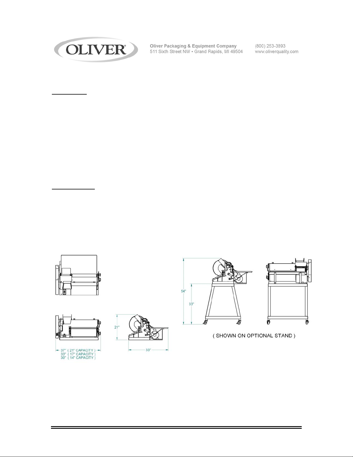
Space Requirements:
Model 641 (All Dimensions are Approximate)
Continued
0641S20004 2-1
Page 6

DESCRIPTION/SPECIFICATIONS (Continued)
NOTE
Standard Electrical Options: (Others consult factory).
½ HP, 1 phase, 60 hz, 115VAC, 7 Amps.
½ HP, 1 phase, 60 hz, 230VAC, 3.5 Amps.
½ HP, 1 phase, 50 hz, 220VAC, 3.5 Amps.
Standard Product Width Capacity
14”, 17”, & 21”
Shipping Weight
14”: 212 lbs. (95 kg) (approximate)
17”: 227 lbs. (102 kg) (approximate)
21”: 257 lbs. (116 kg) (approximate)
Height
Bench Top: 21” (533 mm), (all widths) (approximate)
On Optional Stand: 54” (1372 mm), (all widths) (approximate)
Bench Space (All Dimensions are Approximate)
14”: 30” (762 mm) X 33” (838 mm)
17”: 33” (838 mm) X 33” (838 mm)
21”: 37” (940 mm) X 33” (838 mm)
Options
33” High Metal Stand with 3” Casters.
Above specifications subject to change without notice.
0641S20004 2-2
Page 7
641 DOUGH ROLLER
INSTALLATION INSTRUCTIONS
Dough Roller Installation:
Before starting the Installation process make sure you observe the following three
caution notes.
CAUTION
THE DOUGH ROLLER IS HEAVY, USE PROPER TECHNIQUE WHEN LIFTING.
KEEP BACK STRAIGHT, KNEES BENT, AND LIFT WITH LEGS.
USE GLOVES TO PROTECT HANDS.
CAUTION
NEVER LIFT THE DOUGH ROLLER BY ITS COVERS OR GUARDS.
CAUTION
BEFORE PLACING THE DOUGH ROLLER ON THE TABLE OR COUNTER MAKE
SURE THAT IT CAN SUPPORT THE DOUGH ROLLER’S WEIGHT WHICH IS
APPROX. 260 POUNDS (21”).
Bench Mounted
Select a location for your dough roller which has a substantial mounting surface, (see
the caution note above), and which has electrical service compatible with the load the
machine will place on it as indicated on the electrical data plate of the machine.
Position the machine while it is still in its packaging as close as possible to the desired
end location. Expose the machine by removing the outer packaging. Remove any
straps or fasteners securing machine to crate. Using at least two people, (one in the
front and one at the back of the machine), lift the dough roller from the resting surface of
the packaging and set the machine onto the counter or table as close as possible to the
desired end location. The machine must be sealed to the counter using the included
neoprene rubber under machine edges. Plastic Hole plugs are included to close any
unused holes in machine base.
Continued
0641S20005 3-1
Page 8

INSTALLATION INSTRUCTIONS (Continued)
Optional Stand Mounted
Note:
One bottom guard bolt will have to be removed to mount machine to stand.
Select a location for your dough roller which has a level surface, and which has electrical
service compatible with the load the machine will place on it as indicated on the
electrical data plate of the machine.
Position the machine while it is still in its packaging as close as possible to the desired
end location. Expose the machine and stand by removing the outer packaging.
Remove any straps or fasteners securing machine and stand to crate. Machine will only
go on the stand one way. Using at least two people, (one in the front and one at the
back of the machine), lift the dough roller from the resting surface of the packaging and
set the machine onto the stand. Secure to stand using the provided fasteners.
(see page 14-1)
For all Machines
1. Be sure machine is clean and dry.
2. Make sure power switch is in “Off” position.
3. Check machine nameplate for correct voltage and frequency.
4. Connect machine to a power source that matches nameplate requirements.
5. Switch power “On” and check for proper operation of the machine.
0641S20005 3-2
Page 9

641 DOUGH ROLLER
OPERATING INSTRUCTIONS
WARNING
ALWAYS USE CARE WHENEVER WORKING NEAR THE ROLLERS.
KEEP HANDS CLEAR OF DOUGH CHUTE.
Machine Preparation
1. Make sure the dough chute and trays are dry.
2. Dust the transfer tray (Item 200, page 10-1) with flour, Leave a little extra flour in the
tray to dust the bottom side of the dough before it is sent through the second set of
rollers.
3. Make your initial setting of the roller adjustment levers. Loosen knob, move handle,
then tighten knob. Dial numbers are for reference only.
Dough Preparation
1. Size and shape of the dough ball affects size and shape of the finished crust. For
round pies make a dough piece a fat sausage shape and flatten slightly.
2. Dust the dough pieces with flour before putting them in the machine.
Making a Crust
1. Place the dough piece in the top hopper chute (Item 206, page 10-1) end first.
2. When the dough piece comes out in the transfer tray it should be a little longer than
the diameter of the pie.
3. Dust the top of the dough with flour. There should be sufficient flour in the transfer tray
to dust the bottom of the dough.
4. Turn the dough piece a quarter of a turn in the transfer tray and slide it sideways into
the second pass rollers.
WARNING
NEVER PUSH THE DOUGH WITH THE TIPS OF YOUR FINGERS.
5. The second pass rollers should produce a crust of the proper thickness and about
round in shape. If the crust is too thin, open the lower rollers. If the crust is to thick, close
the lower rollers. If the thickness is right but the crust is too short, make the initial dough
piece bigger and open the upper rollers. If it is too long, make the initial dough piece
smaller and close the upper rollers. When you get the results you want, it is a good idea
to write down the setting numbers if the adjustment levers for future reference.
0641S20006 4-1
Page 10
641 DOUGH ROLLER
TROUBLESHOOTING
WARNING
ALWAYS DISCONNECT THE DOUGH ROLLER FROM THE POWER SUPPLY
BEFORE ATTEMPTING ANY TYPE OF MAINTENANCE TASK, INCLUDING
TROUBLESHOOTING.
The Dough Roller Will Not Start (Motor Is Not Humming)
• The machine is not plugged in.
• There is no power at the outlet. (Check by plugging in a small working appliance,
like a lamp. Check to see if a circuit breaker has tripped. If the circuit breaker has
not tripped and the circuit is still not working have a qualified electrician check the
circuit.)
• The thermal overload on dough roller power switch has tripped – turn machine off,
allow to cool then push switch further “Off” to reset.
• The problem is somewhere else in the electrical system of the machine. (Have a
qualified electrician find and repair the problem.)
The Dough Roller Will Not Start (Motor Is Humming)
CAUTION
DO NOT ALLOW THE MOTOR TO HUM WITHOUT STARTING.
OVERHEATING CAN PERMANENTLY DAMAGE THE MOTOR.
NOTE
A SPECIAL NON-VENTILATED MOTOR MUST BE USED WITH THIS DOUGH
ROLLER.
• The drive system is binding. (Have a qualified service agent check for defective
bearings or other restrictions to free movement.)
• There is mechanical interference between other parts of the Dough Roller. (Have a
qualified service agent evaluate the machine for adjustment or replacement of
defective parts.)
Continued
0641S20007 5-1
Page 11

TROUBLESHOOTING (Continued)
• Broken belt or chain. (Have a qualified service agent evaluate the machine for
adjustment or replacement of defective parts.)
• The motor has failed. (Have it checked by a qualified electrician.)
Lines or Marks in Finished Crust
• The rollers need to be cleaned. (see Maintenance section of this manual)
The Dough is Not Feeding
• Too much flour on dough surface. Dust dough with less flour.
• Dough piece is too thin for current roller setting.
The Dough is Sticking to Rollers
• Dough needs more flour on surface. Dust dough with more flour.
• The rollers need to be cleaned. (see Maintenance section of this manual)
• Missing or improperly installed scrapers. (see Maintenance section of this manual)
0641S20007 5-2
Page 12

641 DOUGH ROLLER
MAINTENANCE
WARNING
ALWAYS UNPLUG THE DOUGH ROLLER BEFORE PERFORMING
ANY TYPE OF MAINTENANCE TASK.
Cleaning
The machine should be cleaned daily, more often during heavy use. Use a damp, soft
cloth on the fixed parts of the machine. Trays and scrapers may be taken to sink for
cleaning.
Removing Scrapers
Remove the scrapers and slides as follows. Reverse the procedures to install them.
1. Long top scraper and tip.
a. Grasp the scraper with both hands.
b. Press down to compress springs and release the retainer.
c. Shift sideways toward the belt guard.
d. Swing the end opposite the guard away from machine.
e. Slide the scraper sideways away from the guard to free the second
end. When reinstalling the scraper make sure the long slot is toward the
belt guard.
2. Long bottom scraper slide and tip.
(first remove the long top scraper as described above)
a. Look under the slide before you attempt to remove it. Note the angles
on the bottom of the slide that hold it in place.
b. To remove the slide grasp it with both hands, one on either side, and
lift sharply to both compress the springs and lift the angles clear of the
pins that support and retain the tray.
c. Pull the tray toward you to remove it from the machine.
3. Short top scraper and tip.
a. Grasp the scraper with both hands.
b. Press down to compress springs and release the retainer.
c. Shift the scraper toward the center of the machine.
d. Swing the end closest to belt guard of the scraper away from the
machine.
e. Slide the scraper sideways away from the center of the machine to
remove it. When reinstalling the scraper make sure the long slot is
toward the center of the machine.
Continued
0641S20008 6-1
Page 13

MAINTENANCE (Continued)
Removing Scrapers (Continued)
4. Short bottom scraper slide and tip.
(first remove the long top scraper as described above)
a. Grasp the scraper with both hands.
b. Lift up sharply to compress the springs and release the retainer.
At the same time, raise the end of the slide so it will clear the lip of the
transfer tray.
c. Swing the inboard end of the scraper which is furthest from the belt
guard toward the roller.
d. Slide the scraper sideways toward the belt guard until the end furthest
from the belt guard clears the stud assembly.
e. Swing the end furthest from the belt guard away from the roller until the
scraper is in front of the stud assembly.
f. Slide the scraper toward the center of the machine to remove it.
g. When reinstalling the scraper you must lift the retainer plate on the stud
assembly furthest from the belt guard so that the hooked end of the
scraper can slide under the plate and around the stud.
General Notes on Disassembly
1. DO NOT LOOSEN THE ACORN NUTS OR THE STUD ASSEMBLIES! They
are factory set to assure proper contact of the scraper tip on the roller.
2. The white nylon scraper tips are easily removed from the scraper bar fro
cleaning by sliding them off with your fingers.
3. WHEN REINSTALLING THE WHITE SCRAPER TIP, MAKE SURE THE
SMOOTH SIDE OF THE TIP (NOT THE STEPPED SIDE) WILL BE TOWARD
THE DOUGH DURING OPERATION!
Lubrication
1. All bearings are permanently lubricated and do not require further lubrication.
2. Add a drop or two of medium weight food safe oil to the oil cup on the chain
idler arm every 200 hours. The cup is located above the shaft of the main drive
pulley and slightly under the dough hopper casting.
Service
If you properly care for your Oliver Products Company Dough Roller, it will give you long,
trouble free service. If replacement parts are required, order them from the factory. Refer
to the Replacement Parts section of this manual for the item’s specific part number.
0641S20008 6-2
Page 14

641 DOUGH ROLLER
RECOMMENDED SPARE PARTS
PART NUMBER PART DESCRIPTION NO. REQ’D
0641-1201-001 Tip-Scraper 7” roller 2
0641-1201-002 Tip-Scraper (14” machine) 2
0641-1201-003 Tip-Scraper (17” machine) 2
0641-1201-004 Tip-Scraper (21” machine) 2
5601-1238 Belt-V (5L580) 1
6301-3609* Motor-1/2 HP, 1-60-115/230 1
5709-1137 Starter-Manual (Power Switch and Enclosure) 1
5708-2430 Heater-Overload (115 VAC) 1
5708-2423 Heater-Overload (220/230 VAC) 1
4560-2508-1109 Knob with stud (1/4-20) 2
5911-7033 Knob (3/8-16) 2
5911-7046 Knob (1/2-13) 2
0641-1017 Main Drive Sprocket 1
0641-0188 Chain assembly 1
*For Other Electrics Contact the Factory
For Service Parts Call Oliver Products @ 800-253-3893
0641S20009 7-1
Page 15
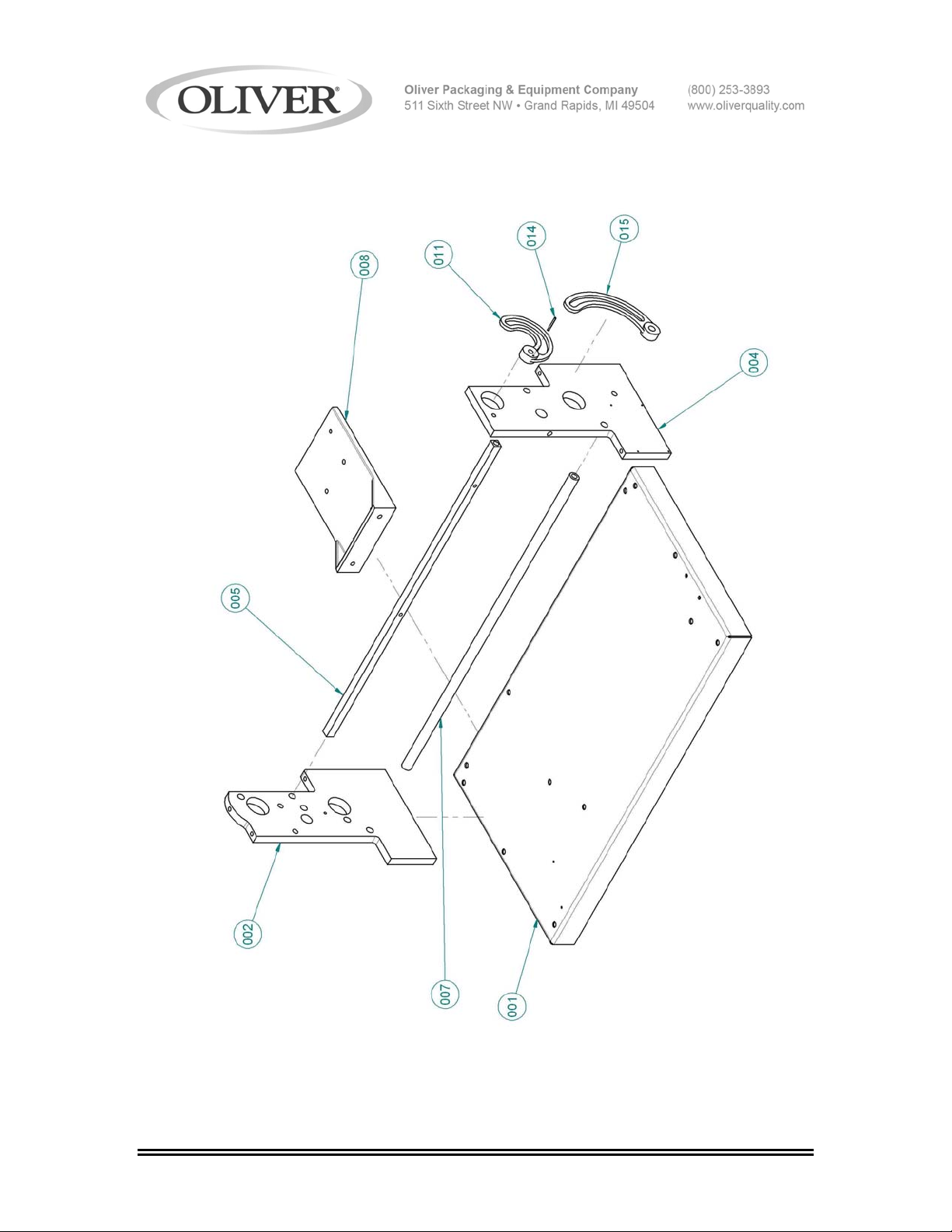
MAIN FRAME
0641S20010 8-1
Page 16

MAIN FRAME PARTS LIST
ITEM NO PART DESCRIPTION PART NUMBER
001 Base RH (14” machine) 0641-1004-0011
001 Base RH (17” machine) 0641-1275-0011
001 Base RH (21” machine) 0641-1048-0011
002 Plate-Side Drive 0641-1209
004 Plate-Side Adjustment 0641-1210
005 Tie Bar (square) (14” machine) 0641-1011-001
005 Tie Bar (square) (17” machine) 0641-1011-002
005 Tie Bar (square) (21” machine) 0641-1011-003
007 Tie Bar (round) (14” machine) 0641-1012-001
007 Tie Bar (round) (17” machine) 0641-1012-002
007 Tie Bar (round) (21” machine) 0641-1012-003
008 Motor Mounting Plate (14” machine) 0641-1203-001
008 Motor Mounting Plate (17” & 21” machines) 0641-1203-002
011 Dial-Top 0641-1100
014 Pin-Spring 5835-6789
015 Dial-Bottom 0641-1101
FOR SERVICE PARTS CALL OLIVER PRODUCTS @ 800-253-3893
0641S20010 8-2
Page 17
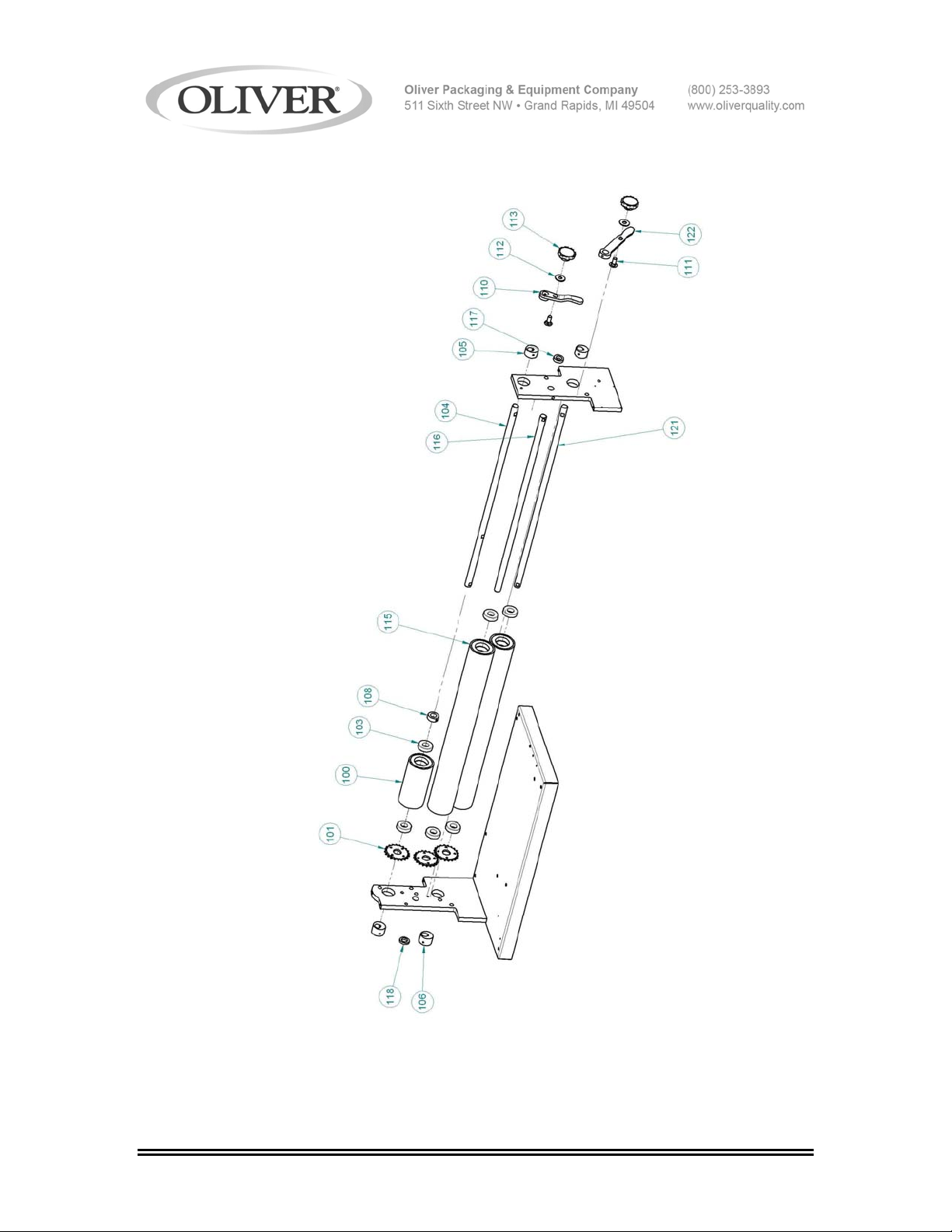
ROLLERS
0641S20011 9-1
Page 18

ROLLERS PARTS LIST
ITEM NO PART DESCRIPTION PART NUMBER
100 Roller 7” 0641-1240-101
101 Sprocket-Drive Roller 4615-4120-3631
103 Bearing 5250-0207
104 Shaft-Top Roll (14” machine) 0641-1016-001
104 Shaft-Top Roll (17” machine) 0641-1016-002
104 Shaft-Top Roll (21” machine) 0641-1016-003
105 Eccentric-Drive Side 0641-1051
106 Eccentric-Adjustment Side 0641-1052
108 Set Collar 5806-7058
110 Handle-Adjustment 0641-1105
111 Screw-Adjustment 0641-0012-008
112 Flat Washer ½ STST 5851-9308
113 Knob (1/2-13) 5911-7046
115 Roller (14” machine) 0641-1240-102
115 Roller (17” machine) 0641-1240-103
115 Roller (21” machine) 0641-1240-104
116 Shaft-Center Roller (14” machine) 0641-1013-001
116 Shaft-Center Roller (17” machine) 0641-1013-002
116 Shaft-Center Roller (21” machine) 0641-1013-003
Continued
FOR SERVICE PARTS CALL OLIVER PRODUCTS @ 800-253-3893
0641S20011 9-2
Page 19

ROLLERS PARTS LIST (Continued)
ITEM NO PART DESCRIPTION PART NUMBER
117 Spacer-Adjustment Side 0641-1074
118 Spacer-Drive Side 0641-1075
121 Shaft-Finish Roller (14” machine) 0641-1014-001
121 Shaft-Finish Roller (17” machine) 0641-1014-002
121 Shaft-Finish Roller (21” machine) 0641-1014-003
122 Handle-Adjustment Lower 0641-0012
FOR SERVICE PARTS CALL OLIVER PRODUCTS @ 800-253-3893
0641S20011 9-3
Page 20
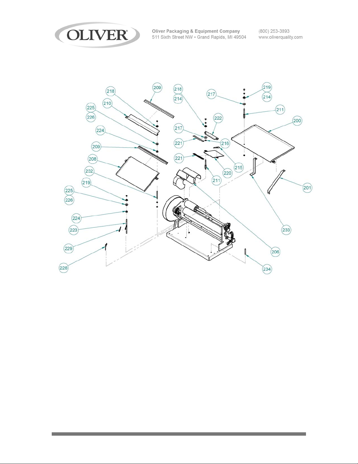
TABLES
0641S20012 10-1
Page 21

TABLES PARTS LIST
ITEM NO PART DESCRIPTION PART NUMBER
200 Tray Assembly (14” machine) 0641-1302
200 Tray Assembly (17” machine) 0641-1104-001
200 Tray Assembly (21” machine) 0641-1104-002
201 Bracket-Support (14” machine) 0641-1084
201 Bracket-Support (17” & 21” machine) 0641-1106
206 Hopper-Dough Chute 0641-1091
208 Scraper Slide Assembly (14” machine) 0641-1143-001
208 Scraper Slide Assembly (17” machine) 0641-1143-002
208 Scraper Slide Assembly (21” machine) 0641-1143-003
209 Scraper Tip (14” machine) 0641-1201-002
209 Scraper Tip (17” machine) 0641-1201-003
209 Scraper Tip (21” machine) 0641-1201-004
210 Scraper Body RH (14” machine) 0641-1141-001
210 Scraper Body RH (17” machine) 0641-1141-002
210 Scraper Body RH (21” machine) 0641-1141-003
211 Post-Scraper 0641-1312
214 Spring-RH 4605-1000-0016
215 Lifter-Spring RH 0641-1053-0001
216 Washer-U 5851-8137
Continued
FOR SERVICE PARTS CALL OLIVER PRODUCTS @ 800-253-3893
Rev. 8/27/05
0641S20012 10-2
Page 22

TABLES PARTS LIST (Continued)
ITEM NO PART DESCRIPTION PART NUMBER
217 Washer 1-3/8 O.D. 4655-0314-1001
218 Locknut & Washer Assembly 0641-1061
219 Retainer-Scraper 0641-1062
220 Scraper Slide Assembly 7” 0641-1147
221 Scraper Tip 7” 0641-1201-001
222 Scraper Assembly RH 0641-1144-0001
223 Support Scraper Slide 0641-1058
224 Retainer-Spring 0641-1034
225 Retainer-Spring Upper 0641-1034-001
226 Spring 15/16 x 2-1/16 4605-1000-0017
228 Support Scraper Slide 0641-1056
229 Link-Strap 0641-1059
232 Support Tray and Slide 0641-1055
FOR SERVICE PARTS CALL OLIVER PRODUCTS @ 800-253-3893
0641S20012 10-3
Page 23

THIS PAGE WAS INTENTIONALLY
LEFT BLANK.
GEN020319
Page 24
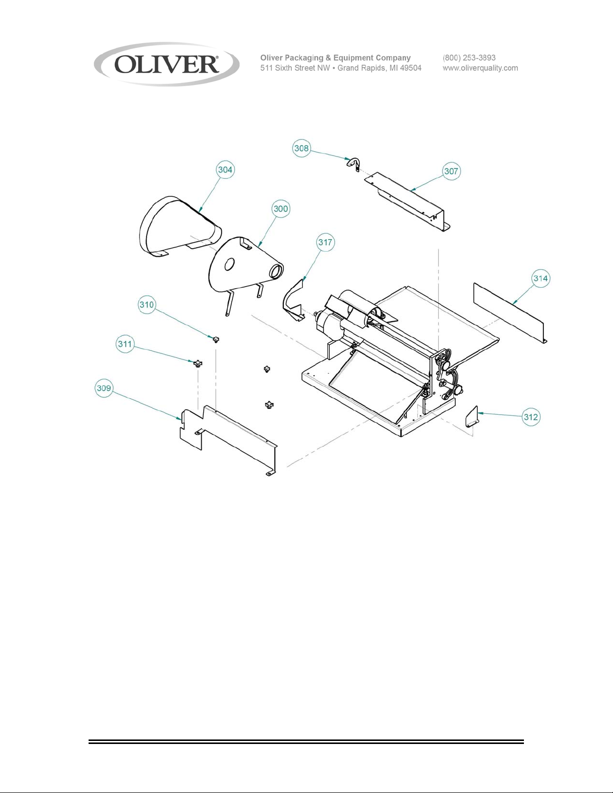
COVERS
REV. 11/10/05
0641S20013 11-1
Page 25

COVERS PARTS LIST
ITEM NO PART DESCRIPTION PART NUMBER
300 Guard Backing Plate 0641-0022-0001
304 Belt Guard 0641-0023-0011
307 Center Roller Guard (14” machine) 0641-0024-0011
307 Center Roller Guard (17” machine) 0641-0024-0001
307 Center Roller Guard (21” machine) 0641-0024-0021
308 Guard- Roller End 0641-0033-0001
309 Rear Guard (14” machine) 0641-0032-0011
309 Rear Guard (17” machine) 0641-0032-0001
309 Rear Guard (21” machine) 0641-0032-0021
310 Knob with Stud (1/4-20) 4560-2508-1109
311 Knob (3/8-16) 5911-7033
312 Outfeed Guard 0641-0028-0001
314 Bottom Guard (14” machine) 0641-0027-001
314 Bottom Guard (17” machine) 0641-0027
314 Bottom Guard (21” machine) 0641-0027-002
317 Chain Guard 0641-0026-0001
REV. 11/10/05
FOR SERVICE PARTS CALL OLIVER PRODUCTS @ 800-253-3893
0641S20013 11-2
Page 26
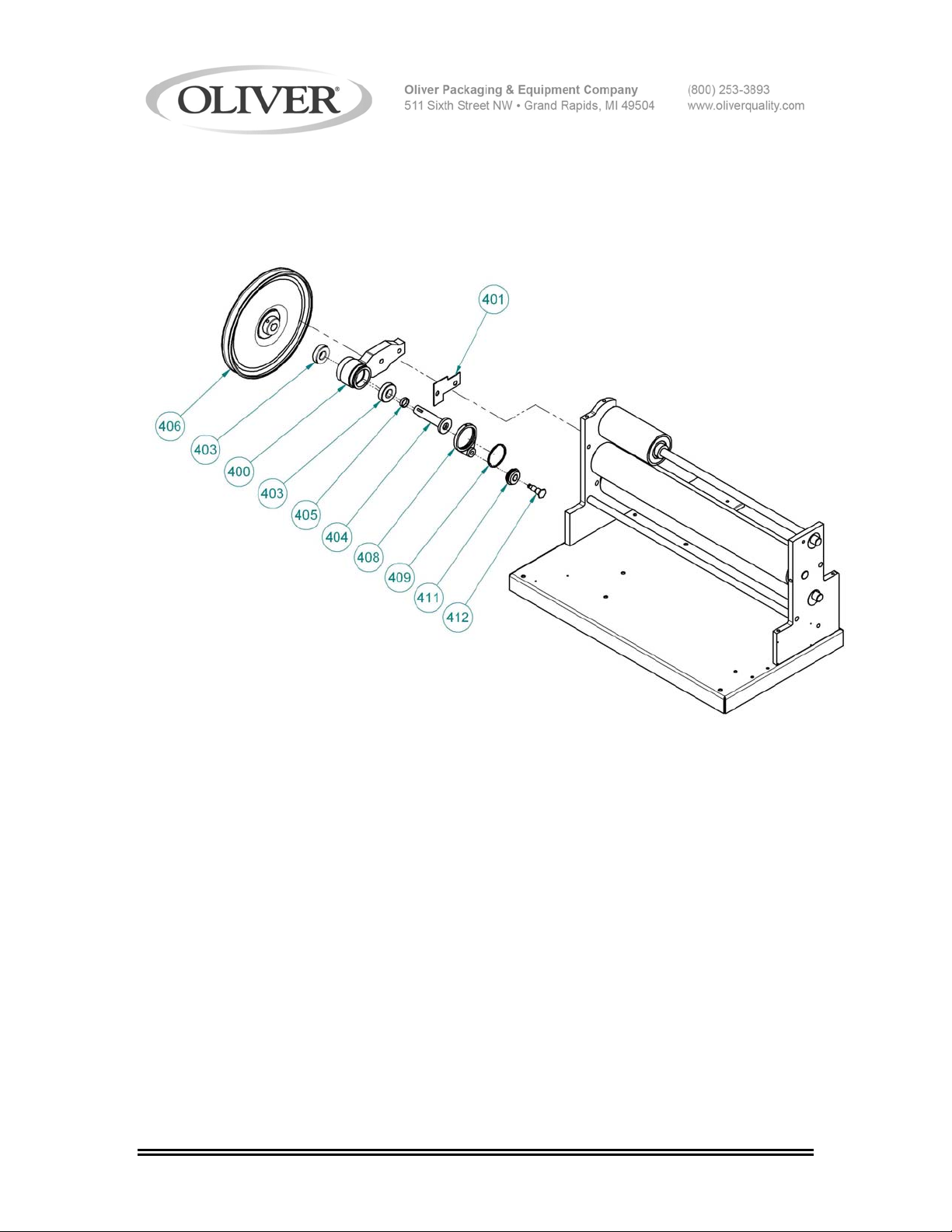
DRIVE
0641S20014 12-1
Page 27

DRIVE PARTS LIST
ITEM NO PART DESCRIPTION PART NUMBER
400 Bracket-Drive Sprocket 0641-1025
401 Shim-Bracket 0641-1353
403 Bearing 5250-0207
404 Main Drive Sprocket 0641-1017
405 Spacer-Main Drive Sprocket 0641-1079
406 Sheave 5L 5615-1629
408 Arm-Chain Takeup RH 0641-1028-0001
409 Retaining Ring 5840-1357
411 Idler Roller 0641-1029
412 Stud-Shaft Idler 0641-1031
FOR SERVICE PARTS CALL OLIVER PRODUCTS @ 800-253-3893
0641S20014 12-2
Page 28
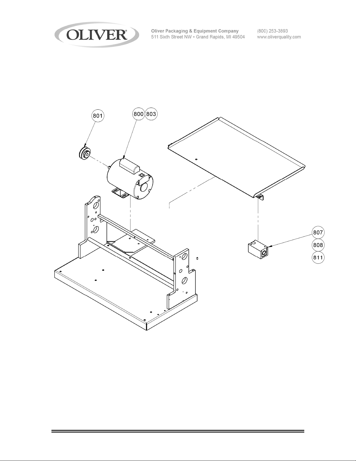
ELECTRICAL PARTS
Rev. 8/27/05
0641S20015 13-1
Page 29

ELECTRICAL PARTS LIST
ITEM NO PART DESCRIPTION PART NUMBER
800* Motor-1/2 HP, 1-60-115/230 6301-3609
801 Sheave 5615-1500
802 Belt-V (5L580) (Not shown) 5601-1238
803 Strain relief 90 deg. 5770-4806
807 Starter-Manual 5709-1137
808* Heater-Overload (115 VAC) 5708-2434
808* Heater-Overload (230 VAC) 5708-2427
811 Strain Relief 5765-1082
*For Other Electrics Contact the Factory
FOR SERVICE PARTS CALL OLIVER PRODUCTS @ 800-253-3893
Rev. 3/23/07
0641S20015 13-2
Page 30
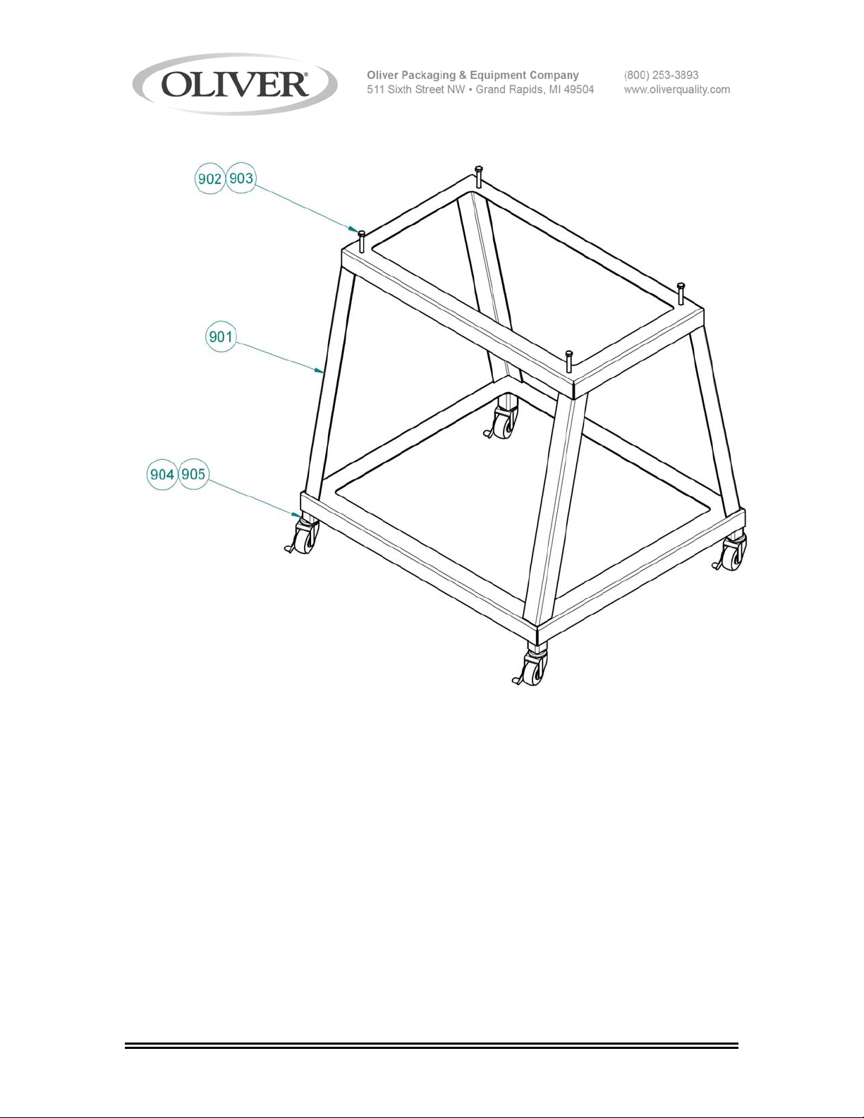
OPTIONAL STAND
0641S20016 14-1
Page 31

OPTIONAL STAND PARTS LIST
ITEM NO PART DESCRIPTION PART NUMBER
901 Stand (14” machine) 0641-1044-101
901 Stand (17” machine) 0641-1044-102
901 Stand (21” machine) 0641-1044-103
902 Bolt 3/8 x 2-1/2 5843-1060
903 Nut 3/8 5832-0522
904 Socket-Caster 5902-2601
905 Caster 2-1/2” 5902-2348
FOR SERVICE PARTS CALL OLIVER PRODUCTS @ 800-253-3893
0641S20016 14-2
Page 32
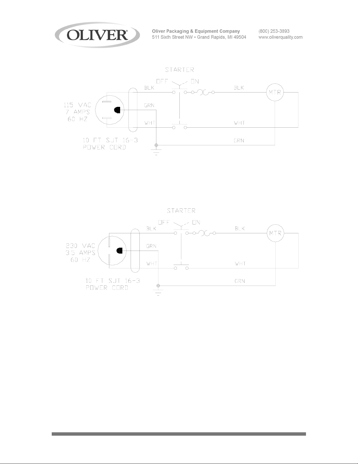
WIRING DIAGRAM 1-60-115
WIRING DIAGRAM 1-60-230
*For Other Electrics Contact the Factory
FOR SERVICE PARTS CALL OLIVER PRODUCTS @ 800-253-3893
0641S20017 15-1
Page 33

WARRANTY
PARTS
Oliver Packaging & Equipment Company (Oliver) warrants that if any part of the equipment (other
than a part not manufactured by Oliver) proves to be defective (as defined below) within one year
after shipment, and if Buyer returns the defective part to Oliver within one year, Freight Prepaid to
Oliver’s plant in Grand Rapids, MI, then Oliver, shall, at Oliver’s option, either repair or replace the
defective part, at Oliver’s expense.
LABOR
Oliver further warrants that equipment properly installed in accordance with our special instructions,
which proves to be defective in material or workmanship under normal use within one (1) year from
installation or one (1) year and three (3) months from actual shipment date, whichever date comes
first, will be repaired by Oliver or an Oliver Authorized Service Dealer, in accordance with Oliver’s
published Service Schedule.
For purposes of this warranty, a defective part or defective equipment is a part or equipment which is
found by Oliver to have been defective in materials workmanship, if the defect materially impairs the
value of the equipment to Buyer. Oliver has no obligation as to parts or components not
manufactured by Oliver, but Oliver assigns to Buyer any warranties made to Oliver by the
manufacturer thereof.
This warranty does not apply to:
1. Damage caused by shipping or accident.
2. Damage resulting from improper installation or alteration.
3. Equipment misused, abused, altered, not maintained on a regular basis, operated carelessly, or
used in abnormal conditions.
4. Equipment used in conjunction with products of other manufacturers unless such use is approved
by Oliver Products in writing.
5. Periodic maintenance of equipment, including but not limited to lubrication, replacement of wear
items, and other adjustments required due to installation, set up, or normal wear.
6. Losses or damage resulting from malfunction.
The foregoing warranty is in lieu of all other warranties expressed or implied AND OLIVER MAKES
NO WARRANTY OF MERCHANTABILITY OR FITNESS FOR PURPOSE REGARDING THE
EQUIPMENT COVERED BY THIS WARRANTY. Oliver neither assumes nor authorizes any person
to assume for it any other obligations or liability in connection with said equipment. OLIVER SHALL
NOT BE LIABLE FOR LOSS OF TIME, INCONVENIENCE, COMMERCIAL LOSS, INCIDENTAL OR
CONSEQUENTIAL DAMAGES.
GEN 040225
Page 34

WARRANTY PROCEDURE
1. If a problem should occur, either the dealer or the end user must contact the Parts and
Service Department and explain the problem.
2. The Parts and Service Manager will determine if the warranty will apply to this particular
problem.
3. If the Parts and Service Manager approves, a Work Authorization Number will be
generated, and the appropriate service agency will perform the service.
4. The service dealer will then complete an invoice and send it to the Parts and Service
Department at Oliver Products Company.
5. The Parts and Service Manager of Oliver Packaging and Equipment Company will
review the invoice and returned parts, if applicable, and approve for payment.
GEN 040226
Page 35

RETURNED PARTS POLICY
This policy applies to all parts returned to the factory whether for warranted credit,
replacement, repair or re-stocking.
Oliver Packaging and Equipment Company requires that the customer obtain a Return
Material Authorization (RMA) number before returning any part. This number should appear
on the shipping label and inside the shipping carton as well. All parts are to be returned
prepaid. Following this procedure will insure prompt handling of all returned parts.
To obtain an RMA number contact the Repair Parts Deptartment toll free at (800) 253-3893.
Parts returned for re-stocking are subject to a RE-STOCKING CHARGE.
Thank you for your cooperation,
Repair Parts Manager
Oliver Packaging and Equipment Company
GEN 040227
 Loading...