

Page 1

OKIFAX OF-150
Modified by Russian representative office of OKI Europe Ltd.
International Standard Version
Short Users Guide
September
OKI
ELECTRIC INDUSTRY COMPANY, LTD.
3,1992
Page 2

PREFACE
This manual is intended to be used for installing and maintaining the OKIFAX OF-150 facsimile
transceiver (International Standard Version of Upgraded Version).
Maintenance of the OF-l 50 is assumed to be conducted to the following levels:
Assembly-level maintenance for mechanical portion
l
Unit-level maintenance for electric portion
0
This manual has been revised for the Upgraded Version. The function items changed or added
for this version are as follows:
Group dial: Increased from one to five groups.
EXTRA FINE mode: Added for the feeder transmission.
Keypad dial for the memory transmission: Available.
Multiple copy: Increased from up to 9 copies to up to 99 copies.
Telephone directory: Separated from the configuration report.
Modified modified READ (MMR): Available for the error correction mode (ECM).
Continuous polling reception: Added.
Print counter: Can be displayed on the liquid crystal display (LCD) in the standby
mode.
0
Copyright 1992
This manual is subject to alteration without prior notification.
OKI
ELECTRIC INDUSTRY COMPANY, LTD.
Page 3

,,.-.;
2
0
z!
i
Page 4

1.1
General Performance
Type of appearance
(1)
Desktop type
Compatibility
(2)
CCITT Group 3 facsimile transceiver
Applicable line
(3)
General switched telephone network (GSTN)
Private branch exchange (PBX)
Communication mode
(4)
Half duplex
Protocol
(5)
CCITT Rec. T.30
Oki
special protocols: Short-cut protocol
High-speed protocol
CCITT Error correction mode ( ECM)
(6)
Coding scheme
(7)
Modified Huffman (MH)
Modified READ (MR)
Modified modified READ (MMR)
MODEM
(8)
CCITT REC. V.29
CCITT REC. V.27 ter
CCITT REC. V.21 channel 2 (300 bps)
Transmission time
(9)
IO sec/CClTT
(10) Minimum scan line time for sending
Oms
(11) Minimum scan line time for receiving
When receiving from OKIFAX:
When receiving from non-OKIFAX:
(9600/7200
(4800/2400
No. 1 sample document
bps)
bps)
Oms
5 ms at 7.7 line/mm
10 ms at 3.85 line/mm
l-l
Page 5

(12) Document width
Max. 280 mm
Min. 148 mm (IS0 A5 size)
(13) Effective reading width
IS.0 84 size
(14) Scanning resolution
Horizontal: 8
Vertical:
PEUmm
Transmission mode: 3.85 line/mm (STD), 7.7 line/mm (FINE) or 15.4
COPY mode:
(15) Automatic document feeder (ADF)
(16) Recording paper and sheet
First cassette:
IS0
A4 size plain paper cut
200 sheet capacity
Second cassette (Option):
IS0
A4 size plain paper cut
500 sheet capacity
Manual loading feeder on the first cassette:
Transparency for overhead projector, applicable.
Sheet size: A4 size only
line/mm
(EX.FlNE).
15.4 line/mm is for the feeder TX only
7.7 line/mm
(17) Recording resolution
Horizontal :
Vertical
Variable
8PEUmm
:
3.85 to 4.28 line/mm, automatically adjusted to the paper length.
:
(STD)
7.7 to 8.56 line/mm, automatically adjusted to the paper length.
(FINE, COPY)
Fixed :3.85 line/mm
(STD)
7.7 line/mm (FINE, COPY)
(18) Image memory
128 k bytes (Basic OF-l 50).
512 k bytes (Optional memory board) can be added.
(19) Handset telephone
(20) Liquid crystal display (LCD)
2 rows of 20 characters for operation guidance, check and various kinds of
information
l-2
Page 6

(20) Liquid crystal display (LCD)
2 rows of 20 characters for operation guidance, check and various kinds of
information
(21) Power source
Nominal input voltage AC 230 V
l-3
Page 7

1.2
General User’s Function
(1) Auto dial
-
One-touch key (24 locations with 24 alternate locations)
-
Two-digit dial (70 locations)
-
Keypad dial
-
Chain dial
-
Mixed dial
(2) Manual dial
(3) Receive mode
-
Auto receive mode
-
Manual receive mode
-
TEL/FAX automatic switchover
(4) Absent mode auto-timer
(5) Automatic redial
(6)
Last number redial
(7)
Telephone directory dial
(8) PHOTO mode
(9)
Voice request (with/without a call-back message)
(10) Local copy including multiple copy
(11) Broadcast (with/without a specified time)
(12) Delayed transmission from feeder
(13) Confidential transmission (with/without a specified time)
(14) Confidential reception (16 mail boxes)
(15) Relay broadcast initiate (with/without a
spe:ified
time)
(16) Polling transmission
(17) Polling reception
(with/without a specified time from a single or multiple locations)
(18) Reverse polling
l-4
Page 8

(19) Transmission preparation
(20) Receive in memory in no paper state
Receive in memory in no toner state
(21)
(22) Sender identification (Sensor ID)
(23) Personal identification (Personal ID)
(24) Closed network
Reduction transmission
(25)
(84
to A4)
(26) Acoustic line monitor
(27) Reports
-
Message confirmation (single location)
-
Message confirmation (multiple locations)
-
Activity report
-
Telephone directory
-
Configuration
1-5
Page 9

1.3
General Maintenance Functions
Self-diagnosis
(1)
-
ROM check
-
RAM check
-
Print test
Scan operation (Adjustment of scanning level)
(2)
LED test
(3)
Tone send test
(4)
High-speed modem send test
(5)
High-speed modem receive test
(6)
Multi-frequency (MF) send test
(7)
Printer unit print test
(8)
Protocol dump
(9)
Service default report
(10)
(11)
System reset
(12)
Remote diagnosis
l-6
Page 10
1.4
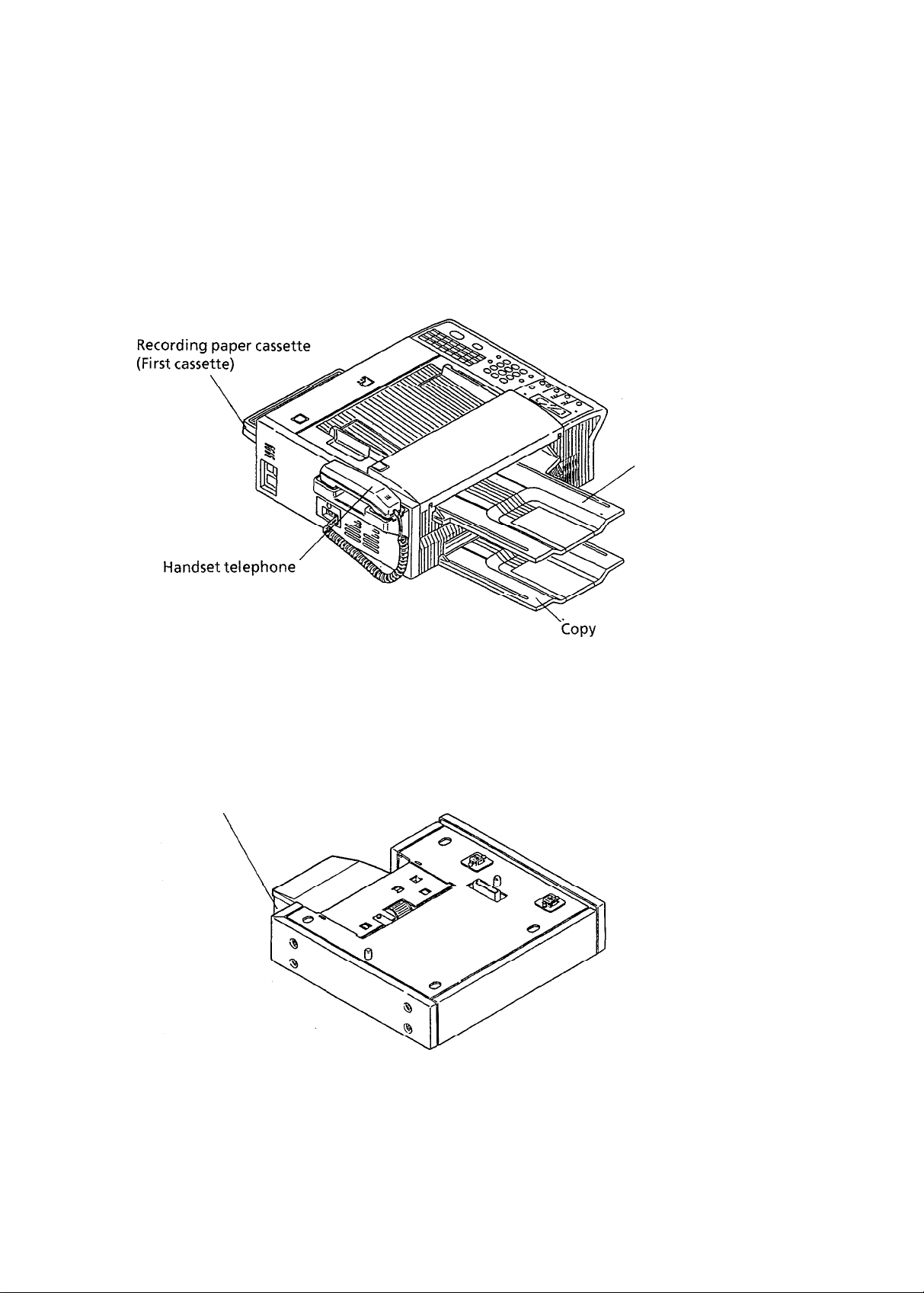
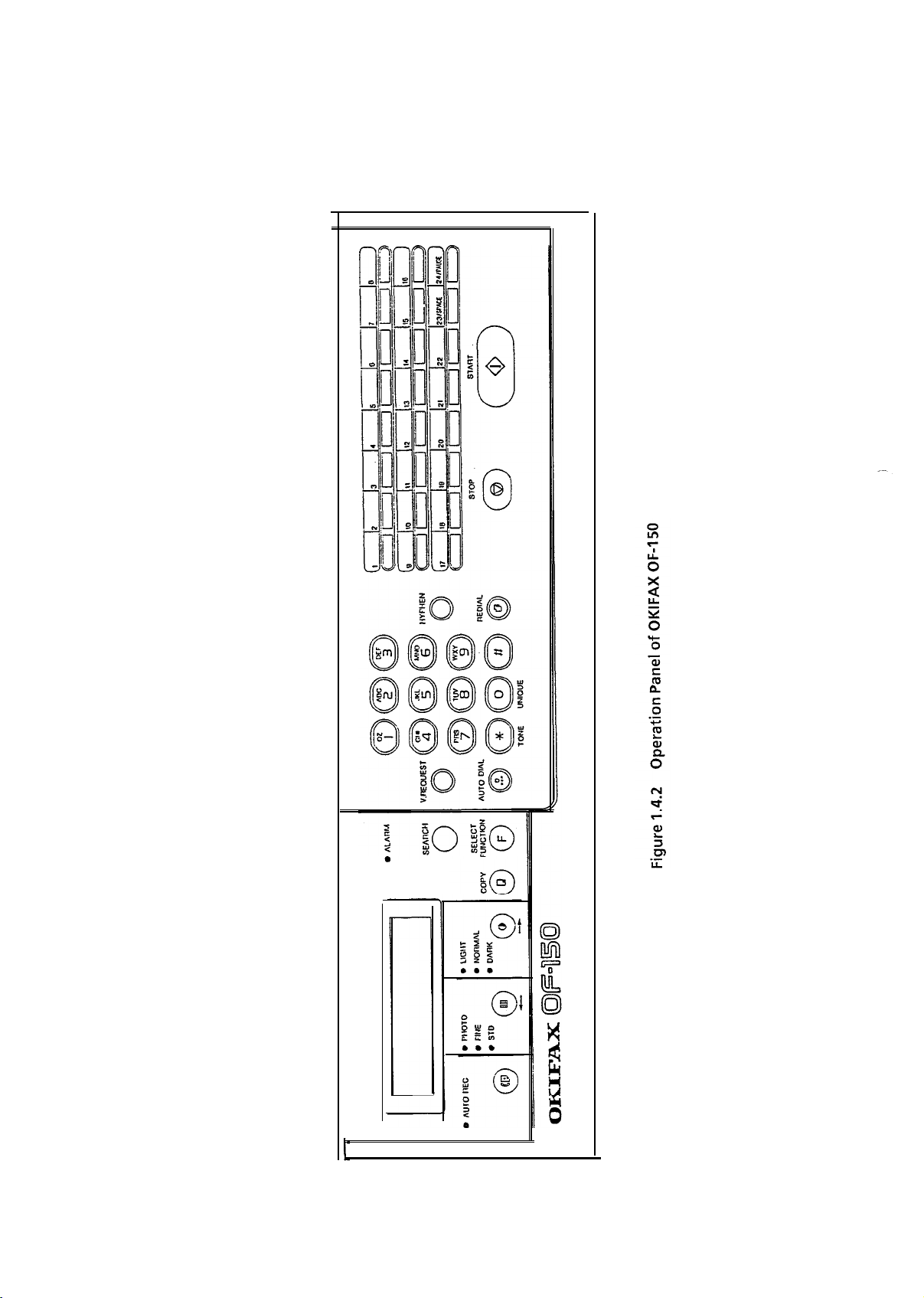
General Appearance
Figure 1.4.1 shows the general appearance of the OKIFAX OF-l 50.
Figure 1.4.2 shows the control panel of the OKIFAX OF-l 50.
, Document
stacker
a. Main Body
Recording paper cassette
(Second cassette)
copy
stacker
b. Second Cassette Cabinet (Option)
Figure 1.4.1
General Appearance of OKIFAX OF-l 50
l-7
Page 11
.
l-8
Page 12

c\_,
CHAPTER 2
SPEClF/CATlONS
Page 13
2.1
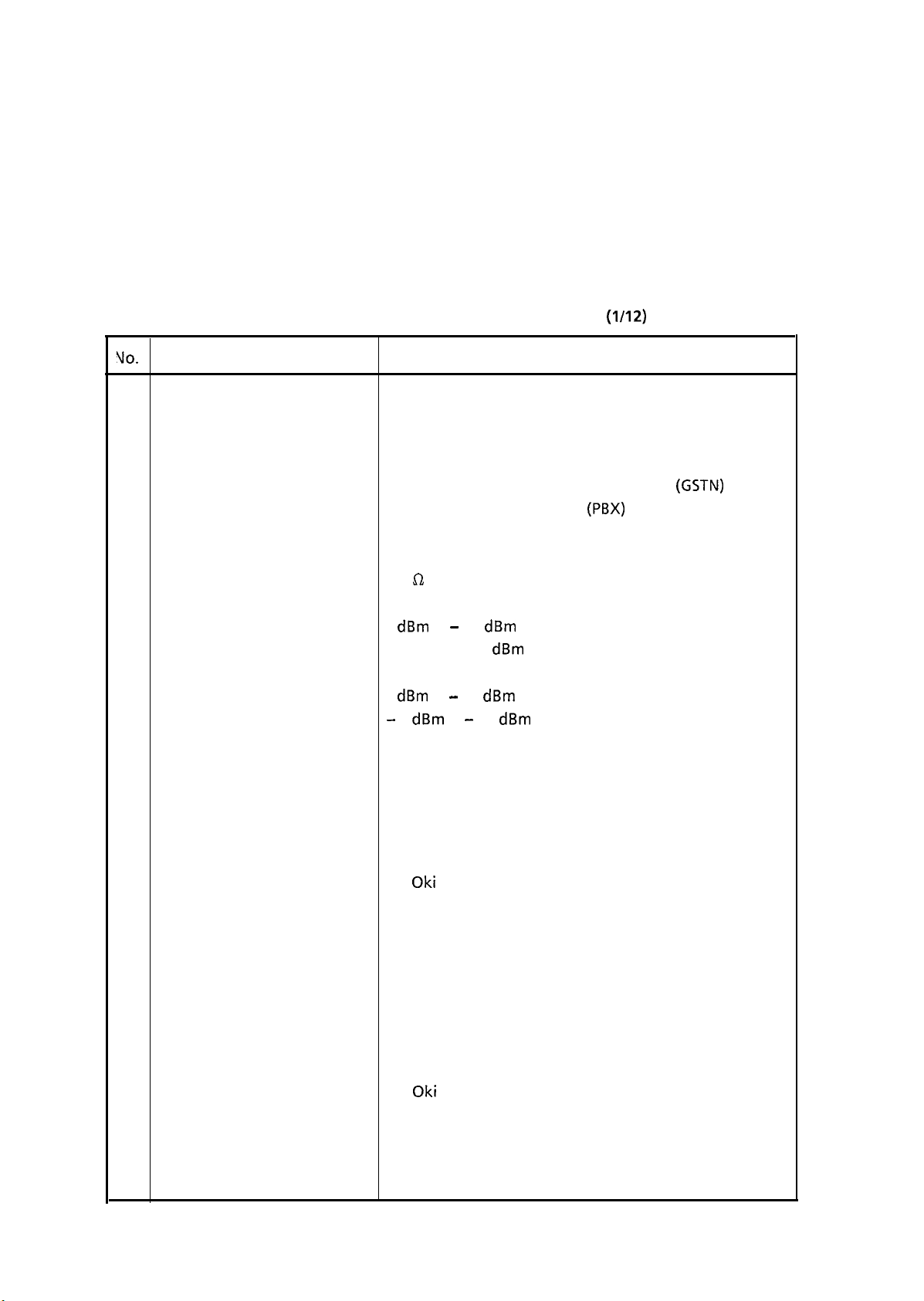
Standard Performance Specifications
Table 2.1.1 shows standard performance specifications.
Note:
S-ON:
FP:
TF:
VO.
1
Type of appearance
2
Compatibility
3 Applicable Line
Line interface
4
1) Impedance
2) Sending power level
Effective if the service bit has been set on.
Function program setting
Technical function setting
Table 2.1.1
Standard Performance Specifications
Item
Desktop type
CCITT Group 3 facsimile transceiver
1)
General switched telephone network
2)
Private branch exchange
600 fi balanced
0
dBm
to - 15
dBm
(Adjustable in 1
Specifications
range
dBm
steps. TF + 22)
(l/12)
(GSTN)
(PBX)
3) Receiving power level
Communication mode
5
6 Protocol
0
dBm
-
6
to - 40
dBm
dBm
to - 46
range or
dBm
range
(Selectable by changing resistors)
Half-duplex
1) CCITT Rec. T.30
2)
Oki
special protocol, short-cut protocol
In multi-page communication, the local transmitting
station can immediately start transmitting the
training for the next page after transmitting EOM
and upon reception of MCF from the distant
receiving station, instead of repeating all procedures
from the beginning of Phase B (which takes about six
seconds). (TF + 08)
3)
Oki
special protocol, high-speed protocol
The T.30 protocol signal from the transmitting
station is sent at message transmission speed instead
of 300 bps. (TF + 08)
2-l
Page 14
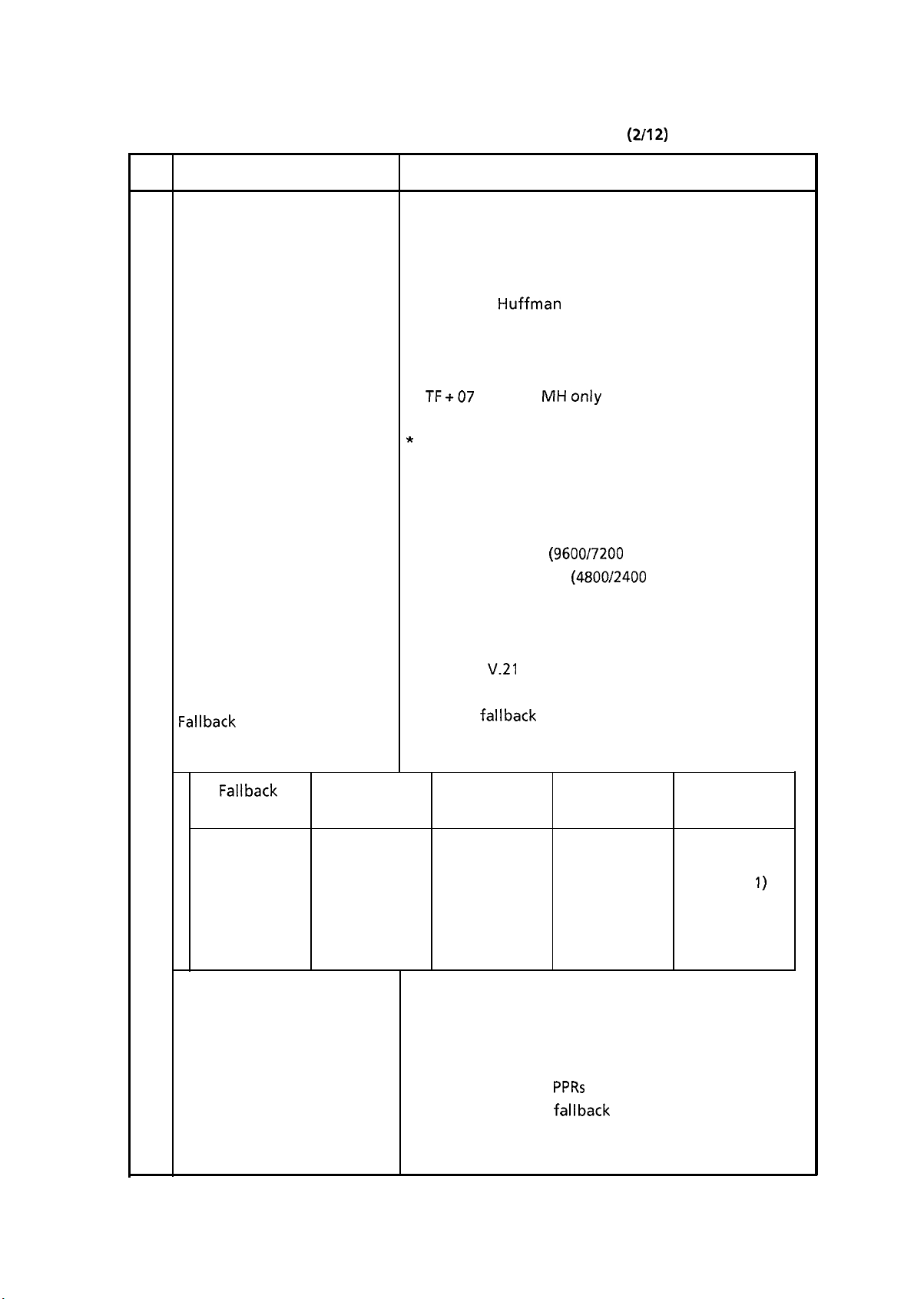
Table 2.1.1
Standard Performance Specifications
(2/12)
No.
7
Error correction
8 Coding scheme
9 MODEM
1) High-speed MODEM
Item
Specifications
CCITT Error correction mode (ECM)
* TF + 31 (To enable or disable this function)
1) One-dimensional coding scheme:
Modified Huffman (MH)
2) Two-dimensional coding scheme:
Modified READ (MR)
Modified modified READ (MMR)
*
TF+07
*
ON:
TF + 44
MHonly
OFF:
Both of MR and MH
(to enable or disable the MMR
communication)
Note: MMR is for ECM communication only.
a)
CCITT Rec. V.29 (9600/7200 bps)
b)
CCITT Rec. V.27 ter (4800/2400 bps)
* TF + 13 (First training speed selection):
9600 bps or 4800 bps
2) Low-speed MODEM
10
Fallback
Fallback
rank
1st
2nd
3rd
4th
CCITT Rec.
Automatic fallback can perform the following sequence
in accordance with FTT, RTN and PPR.
Transmission
speed
9600 bps
7200 bps
4800 bps
2400 bps
When the last trial fails, the transmitting station
transmits a DCN signal to the remote station for
disconnection.
Note 1: Continuous
V.21
channel 2 (300 bps)
Activated by
FTT Times
Activated by Activated by
RTN Times PPR Times
1
1
2
2
PPRs
for the same partial page
within each fallback rank.
1
1
1
1
4 (Note 1)
4 (Note
1)
4 (Note I)
4 (Note 1)
2-2
Page 15
Table 2.1.1
Standard Performance Specifications
(3/12)
do.
Transmission time
11
Minimum scan line time for
12
Item
sending
Minimum scan line time for
13
receiving
Ringing signal detection
14
sensitivity
1) Voltage range
Specifications
10 sec./a
Note:
CCITT
No. 1 sample document
This is Phase C time at
3.85’line/mm
and 9600 bps
in MMR code transmission.
Dms
Uhen
transmitting the current line, the next line is being
read or has been read, and is ready to start transmitting.
3 ms, when receiving from OKIFAX.
5 ms at 7.7 line/mm and 10 ms at 3.85 line/mm when
receiving form non-OKIFAX.
25 to 150 V r.m.s.
Inoperative below 17 V
2) Frequency range
3) Ringing signal detection
time
4) Ringing signal voltage
duration
Type of document to be
15
transmitted
1) Width
2) Length
13to68Hz
One-ringing signal or 5 to 30 seconds.
(Selectable in 5 sec. steps. S-ON. FP + 19)
Longer than 180 (240*) ms
Inoperative if the duration is 90 (150”) ms or less.
Note*: In case that PTT parameter = Norway.
Max. 280 mm (Computer sprocket paper of this width
can be fed with its edges.)
Min. 148 mm (IS0 A5 size)
Min. 128 mm
Max. 500 mm for a single document
Max. 364 mm (B4 length) for multiple documents
Long document detection: 500 mm, or 60 minutes
*TF
+ 21 (To enable or disable long document TX)
An operator can turn on or off the long document
transmission feature for each call in operating sequence.
2-3
Page 16
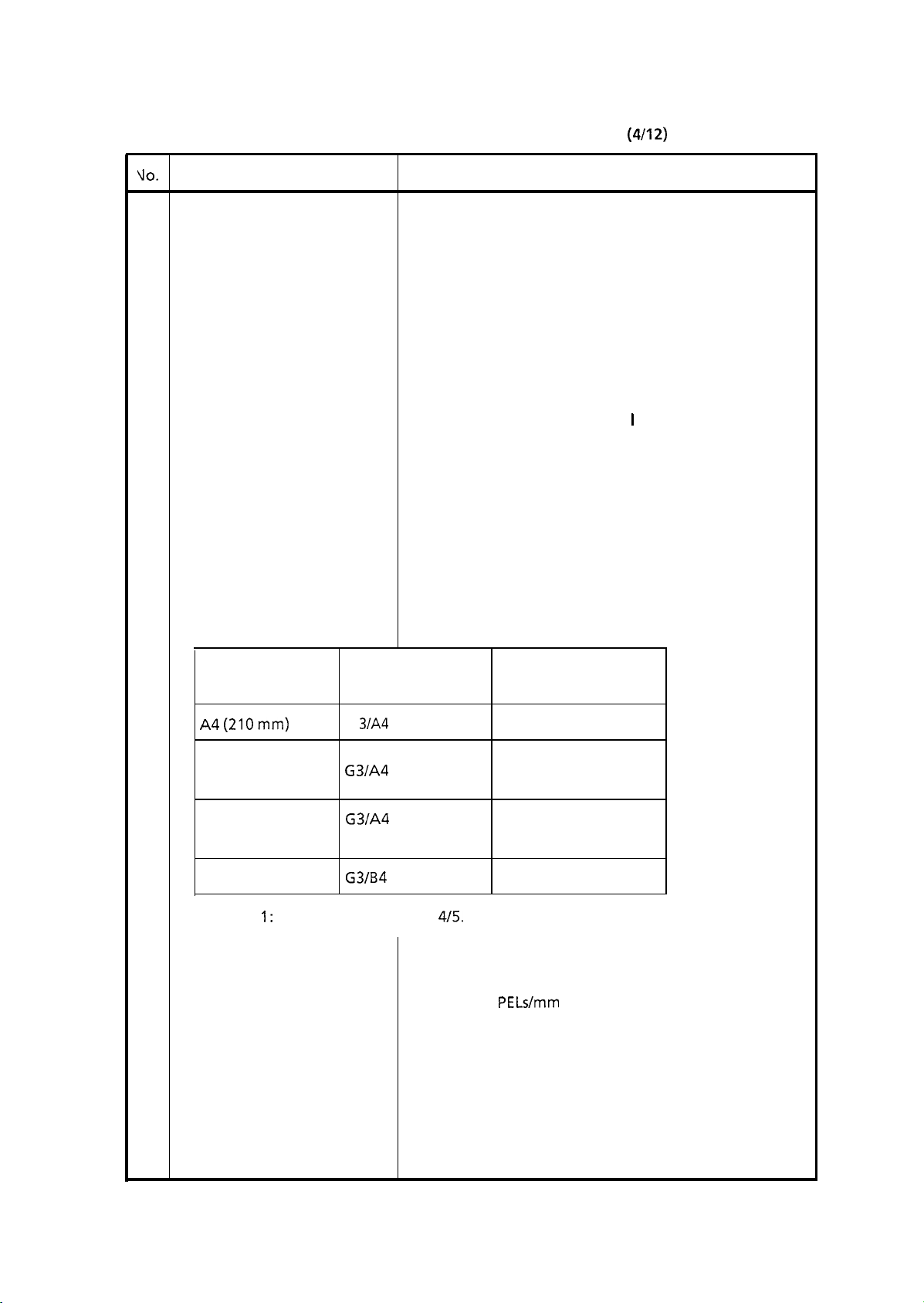
Table 2.1.1
Standard Performance Specifications
(4/12)
VO.
Item
3) Thickness
4) Shape
5) Opacity
16
Automatic document feeder
(ADF)
17 Document skew
Specifications
Based on common bond paper,
a)
0.06 to 0.13 mm for multiple page feeding
b)
Up to 0.15 mm for single page feeding
Rectangular
Documents allowing less than 40% of the scanner source
light to pass through them.
Max. 50 documents/A4 (16 to 24 I b bond paper)
Max. 30 documents/B4
Documents shall be placed face down on ADF stacker.
Max. 2.6 mm skew over a document of A4 length.
For a longer document than A4 length, occurrence of
skew exceeding 2.6 mm over any A4 length is 0.5% or
less.
18
Effective reading width
Document width
A4(210mm)
U.S. letter size
(216 mm)
B4 (257 mm)
B4 (257 mm)
Note
1:
The reduction ratio is
19
Image scanning system
20 Scanning resolution
Communication.
Mode/Picture size
G 3lA4
G3/A4
G3/A4
(Reduction)
(Note 1)
G3lB4
4/5.
2048 bit contact image sensor
Horizontal:8
Vertical :
Note: 15.4 line/mm is for the feeder fransmission only.
Effective reading
width
215 mm
215mm
255 mm
255 mm
PELs/mm
1) COPY mode:
2) STD mode:
3) FINE mode:
4)
EX. FINE mode: 15.4 line/mm
5)
PHOTO mode: 7.7 line/mm, 3.85 line/mm
7.7 line/mm
3.85 line/mm
7.7 line/mm
or 15.4 line/mm
2-4
Page 17
Table 2.1.1 Standard Performance Specifications
(5/12)
No.
Contrast control
Document stacking
Document jam detection
23
Item
Specifications
Automatic background sensing
A continuous document background of 0.3 OD
(optical density) or less will be transmitted as white.
The LIGHT and DARK contrasts will be manually
adjusted to improve image quality.
Up to 297 mm in length.
The documents will be placed facedown on the feeder.
The first sheet will be fed first in the feeder and will exit
facedown on the document stacker.
Maximum sheets on the document stacker:
Transmission will stop and line disconnection will
1)
occur when the end of the document is not detected
within 500 mm after scanning begins (except if the
function “Long document” is set to ON). (TF + 2 1)
50
24
Document jam removal
Recording paper or sheet
25
A jam will also be declared if the document does not
2)
reach the scanning position within 5 seconds after
the start of a document feed.
Note:
1)
2) Manual release
For the first or second recording paper cassette:
1) Type:
2) Size:
3) Weight:
4) Thickness: 0.08 mm to 0.12 mm
5) Condition: New paper
When a jam is detected during message
transmission, the machine will stop, but its
receiving capabilitywill remain valid.
Pressing STOP key feeds out a document remaining
in the feeding path from the feeder.
Plain paper cut (Bond paper)
IS0
A4 (210mm X 297 mm)
16 lbsto
Base weight is defined as the weight of
500 sheets of 431.8 mm by 558.8 mm.
24lbs/base
weight
For the manual loading feeder on the first cassette:
2-5
Page 18
Table 2.1
Standard Performance Specifications
.I
(6/12)
JO.
26
Item
Lecording
)
First cassette
:)
Second cassette (Option)
paper cassette
Specifications
1 Type:
Plain paper cut, transparency for
overhead projector, colored paper,
coated paper, printed paper
)
Size:
)
Weight, thickness and condition:
A4 size only
Same as above.
Jote:
One single sheet only should be loaded on the
manual loading feeder for any one occasion.
‘00 sheets/cassette
100
sheets/cassette
2-6
-
Page 19
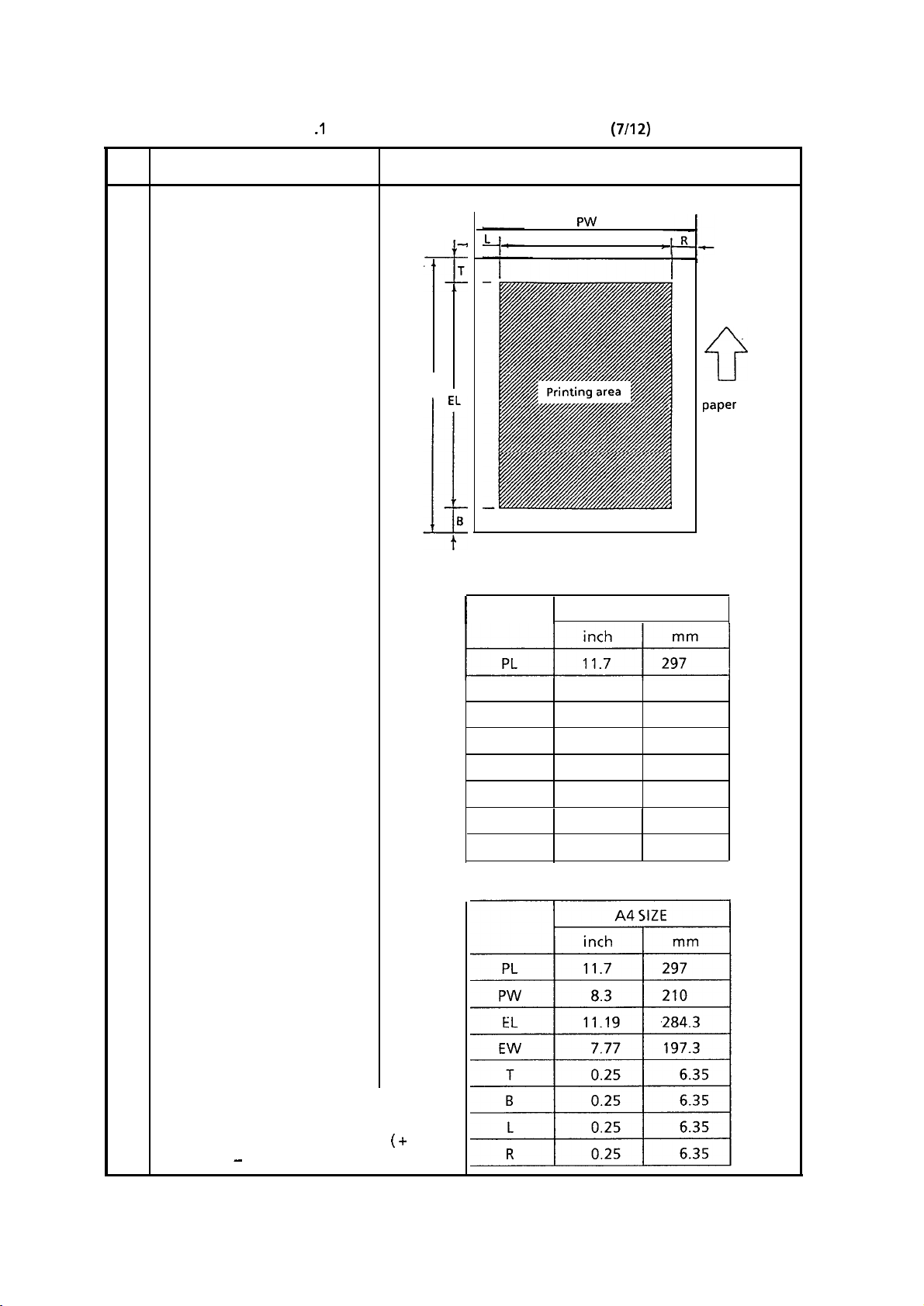
Table 2.1 .IStandard Performance Specifications
(7/12)
No.
Item
27 Effective: recording area
PL
1) Printable area
I
Specifications
PW
EW
A4 SIZE
ii-
Recording
paper
feed
direction
2) Guaranteed printing area
Note: These tables do not include
vertical and horizontal
addressing deviations ( + or
-
2 mm) of recording paper.
PW 8.3 210
EL
EW
T
B
L
R
11.54 293
8.14
206
0.08
0.08
0.08
0.08
2
2
2
2
2-7
Page 20

Table 2.1.1
Standard Performance Specifications
(8/12)
IO.
Item
28 Recording system
Recording resolution
29
30
Skew of recording paper
Specifications
Electra-photographic printing (LED printing)
Horizontal:8
Vertical
Variable:
:
PELs/mm
3.85 to 4.28 line/mm
(STD)
7.7 to 8.56 line/mm (FINE, COPY)
Fixed:
3.85 line/mm (STD)
7.7 line/mm (FINE, COPY)
*
FP + 12 (To enable or disable the variable reduction
for received message)
*
FP + 13 (To enable or disable the variable reduction
for local copy)
Maximum allowable skew is + or - 1 mm over any
advance of 100 mm.
3 1
Copy darkness
32 Copy uniformity
33 Copy stacking
1) Black image:
2) White background:
Greater than 1 .O OD (Optical density)
Not greater than 0.24 OD
(Optical density)
Printed copies will exhibit a uniform density of the
printed and background area:
1)
From edge to edge:
2)
From copy to the next copy:
25% unit
30% unit
The OF-l 50 can discharge printed copies and stack them
faced up.
Maximum sheets on the copy stacker:
100
2-8
Page 21
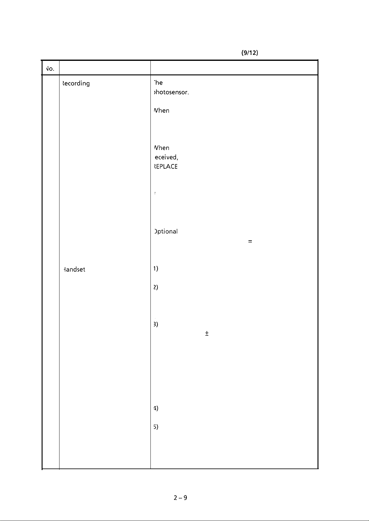
Table 2.1.1
Standard Performance Specifications
(9/12)
\lO.
34
tecording paper running out
mage memory capacity
35
Item
Specifications
-he
OF-l 50 can detect the no paper condition with a
)hotosensor.
When
the paper has run out in the local copy operation,
he LCD display will show “NO PAPER”, and an ALARM
amp goes on with or without an alarm tone.
When
the paper has run out while a message is being
eceived, the LCD display will show “MSG. IN MEMORY
(EPLACE
PAPER”, and an ALARM lamp goes on with or
vithout an alarm tone.
FP + 11 (To enable or disable an alarm tone in the
case of no paper state)
28 k bytes (about 8 sheets)
Optional
memory board:
512 k bytes (totally, 128 + 5 12 = 640 k bytes, about 40
sheets)
36
iandset
telephone
Dialing modes: Tone or pulse, switch selectable.
Tone dial
Minimum pause: 68 ms
Single sending time:
68 ms
Pulse dial
Dial speed: 10 + 1 pps only
Make rate: 67 + 5% or -4%
Minimum pause:
Dial type:
Note:
Normal (Digit 0 = 10 pulses)
Pulse dialling may be inapplicable for some
720 to 920 ms
countries.
Redial key provided
Ringer volume key
Off/Low/High positions selectable
2-9
Page 22
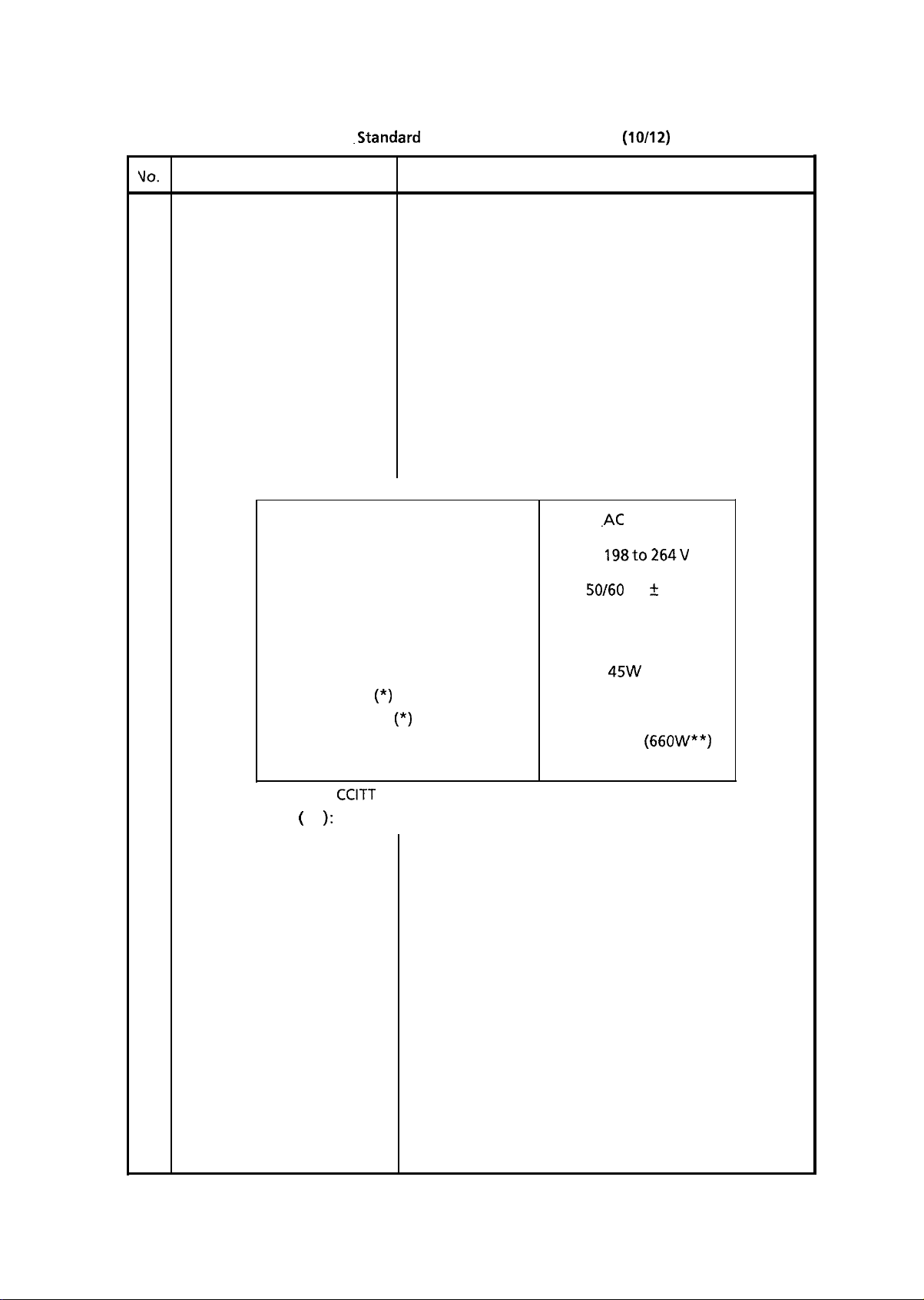
Table 2.1.1
-Standard
Performance Specifications (10/12)
VO.
Item
37 Overheat protection
Power supply unit and power
18
consumption of the machine
Nominal input voltage
Input voltage range
Frequency range
Specifications
The heater of the fuser unit is controlled within the
predetermined temperature range by the thermistor.
If the temperature of the heater exceeds the range, the
LCD displays “PRINTER ALARM 4”.
Furthermore, the built-in thermostat in the fuser unit
prevents the heater from being overheated even in the
event of the failures in the above temperature control
circuit.
.AC
230 V
AC
198to264V
SO/60
Hz 5 2%
Power consumption of the machine
(Typical power)
1) Transmit
2) Receive (*)
3) Local copy (*)
4)
Local copy (All black)
5) Standby
* Chart:
** ():
CCITT
No. 1 sample document
Peak power when the input voltage is 230V.
45W
70W
80W
84W (66OW**)
3ow
2-10
Page 23
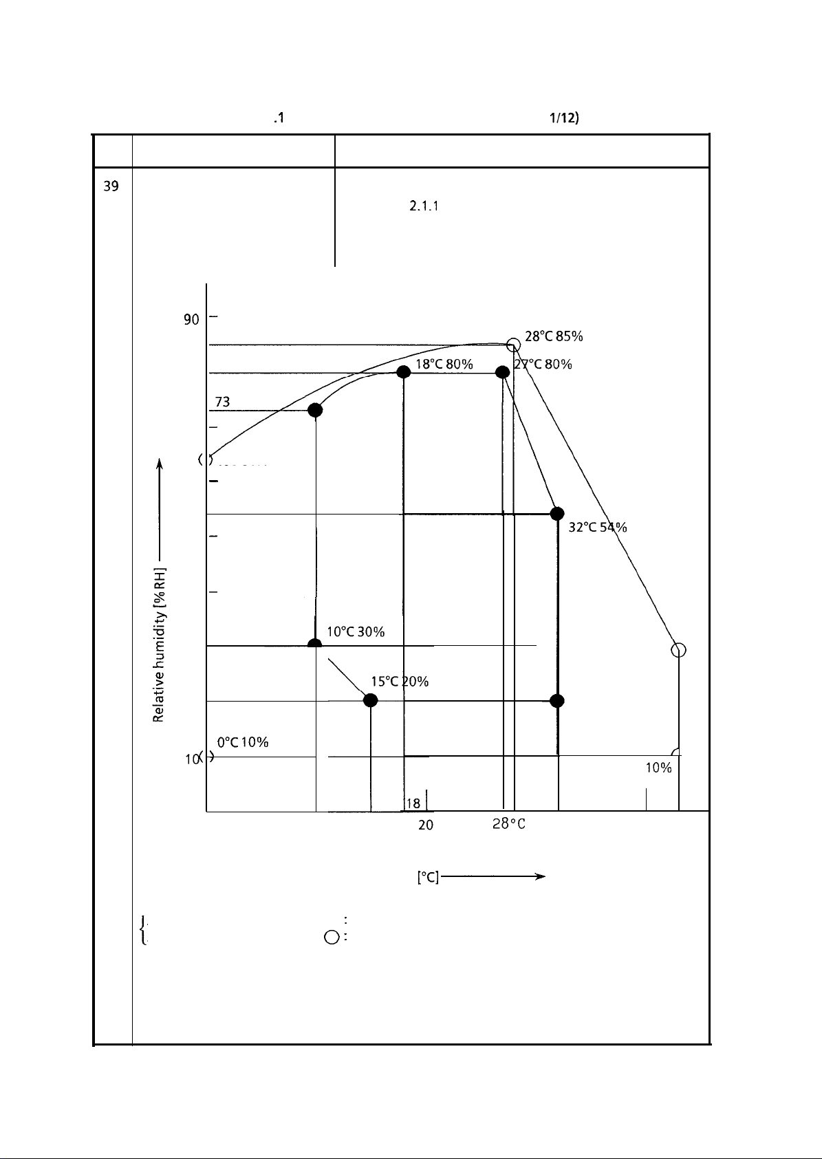
Table 2.1 .IStandard Performance Specifications (1
l/12)
No.
Ambient condition
39
1) Operating condition
2) Storage condition
90
80
70
(
60
50
item
73
-
r/l
0°C 64%
-
54
See Figure
See Figure 2.1.1
10°C 73%
2.1.1
Specifications
40
30
20
0°C 10%
)
lo(
0
10
‘Area enclosed by lines with
enclosed by lines with
Area
15°C
Temperature
l
0 :
Range where printing is guaranteed.
:
Range for storage without power supply
[“Cl p
27°C
28OC
30
I
43°C 29%
32°C 20%
43°C
h
/
10%
40 43°C
Figure 2.1.1
2-11
Ambient Condition
Page 24

Table 2.1.1
Standard Performance Specifications (12112)
JO.
40
Dimension
(Main body)
41
Weight
(Main body)
42 Attachments
(to the main body)
Item
Specifications
1) Width:
2) Depth:
3) Height:
Approx. 20
kg
Approx.
430
mm
Approx. 587 mm
Approx. 185 mm
excluding optional units, attachments and packing
materials.
1)
AC power cord x
2)
Recording paper cassette (A4 size) x
3)
EP cartridge x 1
4)
Toner cartridge x 1
5)
Fuser pad x 1
6)
Handset telephone x 1
7)
Copy stacker x 1
8)
Document stacker x 1
9)
User’s guide x 1
1
1
2-12
Page 25
2.2
Standard User’s Function and Maintenance Function
Table 2.2.1 shows standard user’s functions and maintenance functions.
Note:
No.
1
Auto dial
1) One-touch dial
S-ON:
FP:
TF:
Table 2.2.1
Item
Effective if the service bit has been set on.
Function program setting
Technical function setting
Standard User’s Function and Maintenance Function
Specifications
24 one-touch keys are provided.
Max. 32 digits for each location number.
In addition to an ordinary location number, another
alternate location number can be registered to each
one-touch key.
Purposes of this alternate location number:
1) Faxdial
A fax number is registered as an alternate location
number. When a call to the ordinary location
number is not answered, the alternate location
number will be automatically dialled.
(l/24)
2) Two-digit dial
3) Keypad dial
2) Phone dial
A telephone number for verbal communication.is
registered as an alternate location number. When
the one-touch key pressed without documents on
the feeder after lifting up a handset telephone, the
alternate location number will be dialled for verbal
communication.
* TF + 27 (To select the phone dial feature or the fax
dial feature)
70 different codes are provided.
* Two-digit location code:
Max. 32 digits for code 01 to 30
Max. 20 digits for code 31 to 70
With ten-key pad.
Max. 40 digits for one operation
01 to 70
2-
13
Page 26

Table 2.2.1
Standard User’s Function and Maintenance Function
(2124)
40.
Item
4) Chain dial
5) Mixed dial
Manual dial
2
Receive mode
3
1) Auto receive mode
2) Manual receive mode
3) Telephone/fax automatic
switchover
Specifications
The number of dialling digits can be expanded to longer
digit number by chaining any number of the above I), 2)
and 3).
Type of dialling can be changed from pulse dial to tone
dial halfway in dialling process.
The changing point is specified by the TONE/* key.
With a handset telephone.
Selectable by key operation.
Selectable by key operation.
Selectable by key operation.
The
OF-l 50
recognizes a fax call and a verbal call as
follows:
Absent mode auto-timer
4
5 Automatic redial
If the OF-l 50 detects a call with a CNG signal, it starts an
automatic document receive operation.
If it detects a call without a CNG signal, it sounds the
buzzer to indicate a call. Operator can answer the call by
lifting the handset telephone and pressing the STOP key.
If he or she does not lift the handset within
predetermined time (20 sec. or 35 sec.), the OF-l 50
automatically starts a document receive operation.
*
FP + 10 (To
determine the timer.)
This feature enables automatic switching to the auto-
receive mode at a specified time.
*
FP + 04 (To specify the switching time or disable this
feature)
Dial parameter setting disables or enables this feature,
and specifies redial times and redial interval.
*
See Item 7 of Table 3.7.4 for the service bit condition
depending on PTT parameters.
Last No. redial
6
“REDIAL” key is provided. There is no limit on number
of repeat attempts.
2-14
Page 27
Table 2.2.1
Standard User’s Function and Maintenance Function
No. Item Specifications
7
Group dial
5 dialling groups.
Max. 94 locations.
Telephone directory and
8
location ID
In addition to telephone numbers, an alphanumeric
name can be assigned to each of one-touch keys and
two-digit dial codes, 01 to 30. This name is called a
location ID.
Any location ID can be searched and displayed on LCD.
Then direct dialling to the ID’s station can be performed.
There are two methods of searching:
(1) Searching based on the first character specified.
(2) Searching by displaying all registered location
one after another in the lexicographical order.
Location ID: Max. 15 characters
(3/24)
IDS
Manual transmission CNG
9
Manual reception CED
10
Voice request
11
Call-back message
12
In manual dial mode, a CNG signal can be transmitted
when pressing the START key.
* TF + 17 (To enable or disable this function)
In manual receive mode, a CED signal can be transmitted
when pressing the START key.
*
TF + 18 (To enable or disable this function)
-
A voice request from the transmitter is available only
upon completion of the total message transmission.
-
A voice request from the receiver is available at the
end of each page being received.
The transmitter sends a call-back message to the receiver
only when the receiver does not respond to voice
request of the transmitter.
* TF + 09 (To enable or disable this function)
2-15
Page 28
Table 2.2.1
Standard User’s Function and Maintenance Function
(4/24)
No.
Item
Call-back Message Format: (Example)
(1)
02/61/91 .16:52
(5) PLERSE
(6) a<1 FIBC
(7)
83
3769 1991
CKI WC1234 -v
1234
(1) Date and time
(2) Sender ID
(3)
(4) Session number
(5) Letters “PLEASE CALL BACK”
(6) Sender ID
(7) Sender’s call back telephone numberITS
(2)
NEW
(3)
CENTUFXCO.
CRLL BFlCK
CWPersonal
ID
Specifications
(4)
tam6
13 Local copy
14
Multiple local copy
15 Manual loading feeder
Printing resolution:
Horizontal:8
Vertical
PEUmm
7.7 line/mm or variable
:
* FP + 13 (To enable or disable the variable reduction
feature)
Up to 99 copies.
One single sheet from the feeder above the first
recording paper cassette can be printed.
Example of sheets: Transparency for an overhead
projector
2-16
Page 29

Table 2.2.1
Standard User’s Function and Maintenance Function
(5/24)
No.
16
Broadcast
(Memory transmission)
item
Specifications
Max. 95 remote locations can be specified by the
following means:
One-touch keys, 0 1 to 24
Two-digit dial codes, 01 to 70
One keypad dial number
One group dial number, 1 to 5
One delayed time of calling for this feature can be
specified unless any other delayed calling feature has
been specified.
The combination of one delayed broadcast and one
immediate calling of broadcast is possible.
Memory capacity:
About 8 sheets of CCITT No. 1 sample
documents.
(With an optional memory board,
about 40 sheets of the documents)
17
Delayed transmission from
the feeder
When multiple locations specified for one broadcast,
(1)
The OF-l 50 prints a broadcast entry report, if
specified in operating sequence.
(2) The OF-150 can print a broadcast confirmation
report. (FP + 02 To enable or disable this
printout)
The OF-l 50 can automatically transmit documents at
one specified time.
2-17
Page 30
Table 2.2.1
Standard User’s Function and Maintenance Function
(6/24)
No.
Item
18 Confidential transmission
19 Confidential reception
Specifications
Mail box numbers: 01 to 64 can be specified.
Available remote station’s mail box number:
OKIFAX OF-l 50:
01 to 16
OKIFAX OF-38: 01 to 64
OKIFAX OF-27: 01 to 64
Max. number of pages to be transmitted depends on the
memory capacity of the remote station:
Provided that CCITT No.1 sample documents are
used,
OKIFAX OF-150: See Item 19.
OKIFAX OF-38:
65 sheets
OKIFAX OF-27: 70 to 80 sheets
Delayed time can be specified.
* TF + 12 (To enable or disable this function)
Mail box numbers: 01 to 16
Password to print: Four-digit password for each mail
box
One call only is accepted for all of the mail boxes.
Memory capacity:
OF-l 50 with
Mode
ECM
Non ECM
(G3)
Basic OF-l 50
Max. 2 pages
Max. 8 pages
(Note
1)
a memory board
Max.
10
pages
Max. 40 pages
(Note
I)
Note 1: Provided that CCITT No.1 sample documents are
used.
If a message is left in memory without printing, it will be
erased at 12:00 after 10 days. Electric interruption
longer than 2 days is counted as one day for this time
counting.
Confidential RX report is available. See Item 51.
2-
18
Page 31

Table 2.2.1
Standard User’s Function and Maintenance Function
(7/24)
IO.
20
21
<eiay
broadcast initiate
‘oiling
transmission
:To
be polled)
Item
Specifications
:our-digit
iwo-digit remote list number is required.
ielay
:ode
Ielay
Vlax.
nemory capacity of the relay station:
Ielayed
Ir
Iocument(s) placed on the feeder can be collected by a
.emote station.
-our-digit polling number is provided.
security code for relay broadcast is required.
report can be sent back to the two-digit auto dial
30’s phone number from the relay station.
station:
number of pages to be transmitted depends on the
OF-38: 65 sheets (CCITT No. 1 sample document)
OF-27: 70 to 80 sheets (CCITT No. 1 sample
time can be specified.
TF + 11 (To enable or disable this function)
OKIFAX OF-38 or OF-27
dot.)
22
‘oiling
reception
The
OF-l 50 can collect documents from one or more
*emote
Vlax.
‘ollowing
Ielayed
Nhen multiple locations specified,
Continuous polling reception:
The OF-l 50 continues to poll locations, one after
snother, in a loop until the STOP key is pressed.
stations with four-digit password.
95 remote stations can be specified by the
means:
One-touch keys, 01 to 24
Two-digit dial codes, 01 to 70
One keypad dial number
One group dial number, 1 to 5
time can be specified.
The OF-l 50 prints a multiple poll RX entry report
(1)
if specified in operating sequence.
The OF-150 can print a multiple poll RX
(2)
confirmation report. (FP + 02 To enable or
disable this printout)
k
TF + 06 (To enable or disable this function)
2-
19
Page 32

Table 2.2.1
Standard User’s Function and Maintenance Function
(8/24)
VO.
Item
23 Continuous polling
transmission
24 Reverse polling
25 Transmission preparation
Specifications
Note: Locations for this function should be specified by
the group dialling with or without preceding any
othertype of dialling (One-touch key, Two-digit
auto dial code, Keypad dial number.)
After placing documents on the feeder, pressing the
START key causes the OF-l 50 to enter the polling
transmission state under the same condition as the
previous polling transmission.
* TF + 06 (To enable or disable this function)
Upon completion of usual transmission, the OF-l 50 is
automatically placed into the polling reception state to
poll the same station.
* TF + 05 (To enable or disable this function)
Operator can prepare documents for transmission even
while the OF-l 50 is engaged in message reception. They
will be automatically transmitted upon completion of
the reception.
26
Receive in memory
27
Receive in memory in no
toner state
Operator also can prepare documents for transmission
during transmission from memory.
The OF-l 50 can temporally store a received message in
memory in the following states:
No paper, Cover open,
Paper jam, No toner
* TF + 32 (To enable or disable this function)
* TF + 39 (Should be ON for the no toner state)
The OF-l 50 can temporally store a received message in
memory when toner has run out. The message can be
printed later when toner has been newly supplied or an
operator presses the SELECT FUNCTION key followed by
the YES key under the LCD message “MSG. IN MEMORY
REPLACE TONER CART.” in the standby mode.
* TF + 39 (To enable or disable this function)
* TF + 32 (Should be ON for this function)
2-20
Page 33

Table 2.2.1
Standard User’s Function and Maintenance Function
(g/24)
IO.
28 Sender ID
w01/91
29 Personal ID
(1)
item
The OF-l 50 can transmit a programmed alphanumeric
message, such as company’s name, consisting of up to 32
characters.
* FP + 07 (OUT/IN/OFF)
Sender ID Format: (Example)
(2)
15:06
a<1
ABC 1234 + 3454
(1) Date and Time
(2) Sender ID
(3) Receiver’s
CWPersonal
(4) Session number
(5) Page number
The OF-l 50 can transmit the upper 16 characters of the
sender ID. Personal ID will be displayed on the remote
station’s display and printed on its activity report.
Remote station:
* TF + 10 (To enable or disable this function)
(3)
2880
ID
Specifications
OKIFAX
OF-8/8M/17/17U17H/38/150/7
(4)
No.021
(5)
Wl
30 Transmitting subscriber
identification (TSI) printing
TSI Printing and Local Date and Time Printing Format:
03/81/91
31
Local date and time printing
15:4e
L
Received
TSI
can be printed at the top of the first
received page.
* FP .t 04 (To enable or disable this function)
(Example)
34%.
1999
L
TSI
printing
Local date and time printing
Local date and time can be printed at the top of the first
received page.
Refer to Item 30 for the printing example.
*
TF + 37 (To enable or disable this function)
&
2-21
Page 34

Table 2.2.1
Standard
User’s Function and Maintenance Function
(10124)
10.
Item
32 Closed network
Specifications
The OF-150 compares lower four digits of
TSVCSI
received from the remote station with telephone
numbers registered locally for one-touch dial and
two-
digit auto dial. If unmatched, the communication will be
automatically disconnected.
Purposes of this feature:
1) Receiver side
Prevents direct mail reception
2) Transmitter side
Prevents wrong number calling
*
FP + 08 (To enable or disable this function)
(Reference)
Transmitting subscriber identification
Called subscriber identification
(CSI)
(TSI)
33 Reduction transmission
34
RX reduction printing
35
Copy reduction printing
36
RX split printing
Refer to Item 18, Section 2.1.
To print a received document in one cut sheet as far as
possible, the vertical reduction rate can be automatically
selected from 100% to 90% in printing.
*
FP + 12 (To enable or disable this function)
To print a document in one cut sheet as far as possible in
the copy mode, the vertical reduction rate can be
automatically selected from 100% to 90% in printing.
* FP + 13 (To enable or disable this function)
When a received document is longer than the available
printing length of the cut sheet recording paper, the
document can be split up and printed in two or more
pages.
* FP + 14 (To enable or disable this function)
If this function disabled, the part of the document
beyond the first recording page will be omitted in
printing.
2-22
Page 35

Table 2.2.1
Standard User’s Function and Maintenance Function
(11/24)
No.
37
Copy split printing
Photo mode
38
(Half tone)
Item Specifications
In the copy mode, when a document is longer than the
available printing length of the cut sheet recording
paper, the document can be split up and printed in two
or more pages.
*
FP
+ 15 (To enable or disable this function)
If this function disabled, the part of the document
beyond the first recording page will be omitted in
printing.
32 scale gradation
Three types of Dither matrix:
1)
Net point type
2) Bayer type
3) Eddy type
* TF + 29 (To select type of matrix)
Page retransmission
39
One-touch parameter
40
Image separation:
In PHOTO mode, text portion can be automatically
discriminated from half tone image portion such as
photograph and scanned in two scale gradation to
improve copy quality of the text portion and to shorten
transmission time of the page.
*
TF
+ 29 (To enable or disable image separation)
When the OF-l 50 transmits a page from memory in non-
ECM mode and receives an RTN signal or a PIN signal to
the page from the receiver, the OF-l 50 can transmits the
page for a second time.
*
TF + 33 (To enable or disable this function)
The following features can be programmed to each one-
touch key.
-
Ignoring 1st
-
Protective tone
-
MODEM speed
-
MH only
DIS
2 - 23
Page 36

Table 2.2.1 Standard
User’s Function and Maintenance Function
(12124)
No.
41
Acoustic line monitor
42
Buzzer volume control
43
RX error message
Item
Specifications
The loudness can be adjusted to OFF/Low/High.
*
FP + 05 (To select the loudness of monitoring)
OFF:
Monitoring from off-hook to DCN
Monitoring from off-hook to
DIS
*
TF+Ol
ON:
(Reference)
Disconnect signal (DCN)
Digital identification signal
(DIS)
The loudness can be adjusted to Low/Middle/High.
*
FP + 16 (To select the loudness of the buzzer)
The OF-l 50 can print out an RX error message when
reception of one page is interrupted halfway because
the remote station’s STOP key is pressed, its document is
jammed or line condition is poor.
44 Last call message
confirmation display or
printing
RX Error Message Format: (Example)
:+ REl:E
1
l+‘E STOPPED
The result of the last call can be displayed on the LCD or
printed when the COPY key pressed in the standby
mode.
* FP +
17(To
select display or printing)
*
2-24
Page 37

Table 2.2.1
Standard User’s Function and Maintenance Function
(13/24)
No.
45
Activity report The OF-150 can print out an activity report manually or
Item
I
Specifications
automatically when 30 communications are recorded.
*
REPORT PRINTOUT + 1 (Manual printout)
*
FP + 03 (Automatic printout)
Message Confirmation Report Format:
(Example)
r
4)
TOTFIL
(5) (6)
TIME
(1) IXTI’JITY
S=00:01’
(7)
R=00:
02’
REPORT
(2)
05/01/91
(3)
ID=OKI ABC 1234
(8) (9) (10)
12: 31
(11)
(12)
0000
0000
0000
0000
9080
14C2
41FIQ
68Q0
60R0
0000
Title of the report
(1)’
Date and time when the report was printed
(2)
(3) Sender ID
Total TX and total RX time
(4)
Date of transmission or reception
(5)
Time when the communication started.
(6)
Length of time for which the OF-l 50 was connected to the line
(7)
Identification of the remote station
(8)
Personal
Mode of the communication
(9)
S(Send)/R(Receive)/ECM(Error
M.P.(Multiple
ID/TSI/CSl/Location
ID/Dial number
correction mode)/B.C.(Broadcast)/
polling)/BOX = XX(Mail box number)
(10) Total number of pages in particular communication
(11) Result of the communication
OK/NO/STOP/BUSY/PAPER/COMP.(Completion
polling)/S JAM/R
JAM/POWER/COVER/P.UNIT(Printer
CANCL(Note 1)
(12) Service code
Note 1:
If a confidential message is erazed because left in memory for longer than 10
days, the result will be CANCL and the asterisk(*) mark will be attached to the
service code in the form of *XXXX.
of a broadcast or a multiple
unit alarm)/
2 - 25
Page 38

Table 2.2.1
Standard User’s Function and Maintenance Function
(14/24)
No.
item
46 Message confirmation report
Message Confirmation Report Format:
Specifications
The OF-150 can print out a message confirmation
report manually or automatically in the following cases.
(1) When COPY key pressed immediately after a single
location call, this report can be printed.
(Manual printout)
*
FP + 17 (To select this function or display the result
on the LCD)
(2) If (FP + 01) has been set on, this report is
automatically printed immediately after a single
location call is finished.
(3)
If
(TF
+ 03) has been set on, this report is
automatically printed:
a)
when transmission has a communication error
or,
b)
when the OF-150 receives an RTN signal or a PIN
signal indicating that a transmitted page does
not meet the criteria of copy quality.
(Example)
(1 I
MESS~IGE
(12)SESSION MO.= 631
(13)PQGES =
(1)
Title of the report
(2)
Date and time when the report was printed
05
(4)
DRTE
OS/o1 16: 23
(5)
TIME
(6)
S,R-TIME
04’28”
(14) POSSIBLE ERROR
NEW CENTURY CO.
CRNF
I
RMfiT
(7)
DISTANT STATION ID
l=%E
:
*02
83
I
(2)
@S/01/91
(3)
ID=CiKI
(8)
MODE
63 -s 05
(3) Sender ID
(4)
Date of transmission or reception
(5)
Time when the communication started.
(6)
Length of time for which the OF-l 50 was connected to the line
(7)
Identification of the remote station
Personal
(8)
Mode of the communication
IDKSVLocation
ID/Dial number
S(Send)/R(Receive)/ECM(Error correction mode)
(9)
Total number of pages in particular communication
ON
WC 1234
I=&
16: 27
(IO)
REJ-LT
OK
(11)
0800
2 - 26
Page 39

Table 2.2.1
Standard User’s Function and Maintenance Function
(15/24)
No.
Result of the communication
(10)
Service code
(11)
Session number is printed if (FP + 07) has not been set to OFF but to OUT or IN and
(12)
this report is caused by (TF + 03).
Number of pages stored in memory
(13)
This item is printed only in the case that transmission from memory is carried out.
Page numbers of the pages to which an RTN signal or a PIN signal received.
(14)
The asterisk(*) mark indicates that retransmission of the page met the criteria of
copy quality.
47
Broadcast entry report
Item
Specifications
OK/NO/STOP/BUSY/PAPER/S JAM/R JAM/POWElUCOVER/P.UNIT(Printer unit
alarm)
The OF-l 50 can print out a broadcast entry report if
specified during operating sequence of a broadcast.
Broadcast Entry Report Format:
(Example)
SESSION NO. = 011 (Note
DELRY
TINE =
ONE TOUCH
01 = NEW
RUT0 DIQL
70
KEYPQD
LOCATION ID
CENTmY
= 444
555
BRQfWCfXT
1)
it:05
co.
ENTRY
REPORT
27/08/92 12:00
ID=OKI ABC 1234
LOCFlTION
ID
Note 1: Session number is printed if (FP + 07) has not been set to OFF but to OUT or IN.
2 - 27
Page 40

Table 2.2.1
Standard
User’s Function and Maintenance Function (16/24)
NO.
Item
48 Broadcast confirmation
report
Broadcast Confirmation Report Format:
BROfUlCFSST CQNFIRMflTION
SESSION
PAGES
STRRT
TOTAL TIME =
ONE TOUCH
No.
= 011
(Note 1)
= 01
TIME =
01 = NEW CENTURY CO.
27/08/92 12:05
00:00’27’
LOCQTION
ID
Specifications
The OF-l 50 can print out a broadcast confirmation
report manually or automatically.
* COPY key (Manual printout): Pressed immediately
after a broadcast.
FP + 17 (To
select this function or display the result of
the broadcast on the LCD for the COPY key
operation)
*
REPORT PRINTOUT + 2 (Manual printout)
* FP + 02 (To enable or disable automatic printing)
(Example)
REPORT
PRSES
01
27/08/92
ID=OKI RBC
RESULT LOCRTION
OK
12: 06
1234
ID
PGGES
RESULT
AUTO DIRL
70 = 444
KEYPQD
555
01
01
OK
OK
Note 1: The session number is printed if (FP + 07) has not been set to OFF but to OUT or
IN and this report is activated by (FP + 02).
2 - 28
Page 41

Table 2.2.1 Standard User’s Function and Maintenance Function
(17/24)
No.
49
Multiple polling reception
Item
entry report
PIXSWORD = 0000
DELFlY
TIME =
OMTCGCH
01 = NEW CENTURY CO.
GUT0 DIGi_
70 = 223
KEYPRD
Specifications
The OF-l 50 can print out a multiple polling reception
entry report if specified during operating sequence of
multiple polling reception.
Multiple Polling Reception Entry Report Format:
MULTIPLE POLL RX ENTRY REPORT
05/01/91
ID=OKI FlBC
10:12
LOCRTION ID
228
LOCATION ID
(Example)
10:09
1234
Multiple polling reception
50
confirmation report
Multiple Polling Reception Confirmation Report Format: (Example)
PQSSWORD
STFlRT TIME= 05/01/91
TOT& TIK
OMTOUCH
01 = MWCENTURY CO. 01
RUTODIM-
70 = 223
KEYFGD
228
MULTI-POLL RX
=0m0
=
00:00'40"
LDCOTION
ID
10:12
PRGES
01
01
The OF-150 can print out a multiple polling reception
confirmation report manually or automatically.
*
REPORT PRINTOUT + 3 (Manual printout)
*
FP + 02 (To enable or disable automatic printout)
CONFIRMQTION
RESULT
OK
OK
OK
REPORT
05/01/91 10:14
ID=OKI FlBC
LOCFlTION
1234
ID
PffiES
RESULT
2-29
Page 42

Table 2.2.1 Standard User’s Function and Maintenance Function (18/24)
No.
51
Confidential reception report
Item
Confidential Reception Report Format:
CONFIDENTWIL
DQTE
OS01
TIME
ii:21
S,R-TIME
00’ 10”
Specifications
The OF-l 50 can print out this report automatically on
completion of a confidential reception.
*
FP + 18 (To enable or disable this function)
(Example)
RX REPORT
05/01/91 11c21
DISTRNT STFlTICR4
NEW CENTURY CO.
ID
ID=CKI FlBC
MODE
BOX=01
01
FWES
1234
RESULT
OK
0000
2-30
Page 43

Table 2.2.1
Standard User’s Function and Maintenance Function
(19/24)
No.
52
Telephone directory
Telephone Directory (PI) Format: (Example)
TELEPHONE DIRECTORY
ONE TOUCH
Item
1
2
3
4
5
6
7
8
9
10
11
12
13
14
15
16
17
18
19
20
21
n
23
24
LOCGITION
Specifications
This directory is printed manually.
(REPORT PRINTING + 4)
TELEPHQNE DIRECTORY
26/08/92 17:27
ID=OKI FlBC
ID
0
1111234
ORD
D
2221234
ORQ
D
ORD
Q
ORQ
OR:
0
ORQ
OR:
OR:
Q
ORQ
0:
Q
ORB
ORE:
ORZ
Q
ORQ
0
ORQ
Q
ORQ
Q
ORQ
ORi
Q
ORi
Q
2424111
TEL NO.
Pl
1234
PRM. 1:MODEM
3:MH ONLY
RFlTE
(000~
(000)
(000)
(0001
W003
ma0)
(8801
(0001
ma03
(000)
(0001
(0001
2:ECH0
PRM.
123
Page 44

Table 2.2.1
Standard User’s Function and Maintenance Function
(20/24)
IO.
Item
Telephone directory (P2) Format:
TELEPHONE DIRECTORY P2
TELEPHOM
DIRECTORY
WTODIRL
01
02
ii
05
E
06
09
::
12
13
14
15
16
17
is
19
20
21
z
24
25
26
z
G
RUTODIN_
3lD
3x2
z
390
41D
433
45Q
47Q
49Q
51D
z
57Q
59Q
610
Ei
(Example)
Q
1234567
0
7654321
0
Q
Q
Q
Q
;
Q
Q
Q
Q
Q
GUT0 DIN
Specifications
26A3w92 17:27
ID=OKI
320
z
SLJ
40Q
42Q
z
.z
E::
568
z
62Q
64Q
z
70Q
9999999
ABC1234
2 - 32
Page 45

Table 2.2.1
Standard User’s Function and Maintenance Function
(21/24)
Item
Telephone directory (P3) Format:
TELEPHONE DIRECTORY P3
#l #2 #3 #4 #S =GFGW
#l
ONE
TWCH
1
224
WI-0 DIRL
01 70
82 ONE
TOUCH
WTO DIRL
NUMBER
(Example)
Specifications
26&a/92 17:27
ID-1
MC 1234
84
#5 ObE TWCH
Note 1: Page
RUT0
DIfiL
ONE TOUCH
WI-0 DIQL
RUT0
DIM_
3(P3)
is printed if any number of groups has been registered.
2-33
Page 46

Table 2.2.1
Standard User’s Function and Maintenance Function
(22/24)
No.
53
Configuration report
Configuration Report Format:
Item
FUNCTION LIST
Ol:MCF CSINGLE-LOC. 1
OFF OFF
04:QLITO-REC TINER
OFF
07:SENDER
OUT
l@:&‘V
2esEc
13:COPY REDUCTION
ON
16:EuzER
MIDDLE
19:RING RESPONSE
iRING
TEL NO.
FULL NO.
SECURE
REMOTE LIST NO.
REDIFIL
DIFlL TONE
MF/DP
DP
RsirE
DP
Mw<E RFlTIO
DP
DIRL
MF DLlRFlTION
RUT0 STRRT
PTT PRM.
ID
TIMER PRG.
VOLUME
CODE
TRIES
TYPE
Specifications
This report is printed manually.
(REPORT PRINTING + 5)
(Example printed out immediately after
performing system reset, setting the service
bit on, and programming a sender ID)
CONFIGURf?TIQN
02:NCF
Note 1
I
= 0000
:
2TRY
ON
NF
iBpP5
39%
1mc
OFF
01: INT’L
CWLTI-LOC.
E)S:l’iUNITOR
08:CLOSED NETWORK
ll:No PRPER CRLL
14:RX SPLIT PRINT
17:
VOLUME
LOW
OFF
OFF
ON
MSG. CONF. DSP/PRT
DISP
1
/
REDI& INTERURL
BUSY
TONE
PRX
LINE
RCCESS
DIGIT
PBX
TYPE
26&G/92 18:15
ID=OKI RBC
03:WR
FULL PRINT
ON
06:REMOTE DIAG.
OFF
09:TX
MODE
STDhdORMFIL
12:RX REDUCTION
ON
15:COPY SPLIT PRINT
ON
18: CONF. RX
ON
Note
1
3MIN
ON
OFF
NORMFlL
1234
DEFQULT
REPORT
\
\lote 1: These parts are not printed if the service bit has been set to OFF.
2-34
Page 47

Table 2.2.1
Standard User’s Function and Maintenance Function
(23/24)
No.
54
Service default report
Service Default Report Format:
Item
This report can be printed manually for maintenance
purpose. (REPORT PRINTING + 0)
SERVICE
OI:MONITOR CONT.
OFF OFF
04:TSI
07:FlH
PRINT
ON
ONLY
OFF
10:PERSoNFlL
ID
ON
Specifications
(Example printed out immediately after
performing system reset, setting the service
bit on and programming a sender ID)
DEFfWLT
02:PROTOCOL
05:RNERSE POLL
OFF
0B:SHORTEN
ON
1l:RELRY
ON
IMIP
PROTOCOL
B.C.
INIT
REPORT
25Azw32 10:59
ID==1 RBC
03:ERR.
OFF
06:CONTINUOLlS
OFF
09:CALL
ON
12:COtdFIDENTIRL
ON
1234
REFQRTCMCF)
POLL
BFICK MSG
TX
13:H/MoDEM RRTE
9600
16:ToM
FOR
OFF
19:oFF
OFF
22:FITTEbWTOR
3
25:DOc. END FEED
0
2G:SER'JICE
ON
3l:CCITT EUI
ON
34:
37:TWWDATE PRINT
OFF
40:RX.ERR.MSG.PRINT
ON
ECHO
HzJx BYWSS
DE
BIT
14:IGNORE IST
OFF
17:wwJfx
ON
20:
23:NL
4 DB
26:SENSORCAL.
OFF
29:UIDEO PmwmER
1*1
32:NOFwERFzX
ON
35:
38:XTTowLLE
000
41:
DIS
TX
CNG
EGWLIZER
lS:CED-DIS
m:riiwJQL
21:LoNG WC.
24:DOC. TOP FEED
27:PHONE
30:MDYAttlY
33:PAGERE_TRWS?lIT
36:
39:M)
42:
75RSEC
OFF
OFF
0
OFF
mY
ON
TONER
ON
TIMER
RX CED
TX
DIRL
MEM.RX
43:
46:FRINTCOWT
OFF
DSP.
44:tWlR WTION
ON
2-35
45:75%
ON
REDUCTION
Page 48

Table 2.2.1
Standard User’s Function and Maintenance Function
(24/24)
JO.
Item
55 Maintenance facilities
1) Local test
a) Self-diagnosis
ROM check
RAM check
Print test
Printout of the following counters for routine
maintenance:
TX page counter
RX page counter
b)
Scan operation (Adjustment of scanning level)
c)
LED test
d) Tone send test
e)
High-speed modem send test
f)
High-speed modem receive test
g)
Multi-frequency (MF) send test
h)
Printer unit print test
Specifications
2)
Display and clearing of counters related to the
printer unit, for routine maintenance
-
Print counter
-
Drum counter
-
Fuser counter
-
Toner counter
3) Protocol dump
4)
Service default report (Refer to Item 54)
5) System reset
-
All data clear
-
Location data clear
-
Configuration clear
-
TX page counter clear
-
RX page counter clear
6) Remote diagnosis
2-36
Page 49

2.3
Reliability
Table 2.3.1 shows reliability items.
Table 2.3.1 Reliability
\lO.
1
Document feeder
Feeder separation rubber
2
item
useful time
Recording paper feeder
3
EP cartridge life
4
Toner cartridge life
5
Specifications
Jam occurrence and misfeeds in the automatic document
feeder will be less than one in 500 operations
for all
specified documents.
The separation rubber will not require replacement for
at least 30,000 documents fed.
Jam occurrence in the automatic feeder will be less than
one in 1500 operations and misfeeds will be less than
one in 500 operations, for all specified recording paper.
7,500 sheets for one page per one job.
15,000
sheets for continuous printing.
1,500 sheets for the first toner cartridge to a new EP
cartridge,
2,500 sheets for the second or later toner cartridge to a
new EP cartridge.
Fuser pad life
6
7
Battery
MTBF
8
2,500 sheets.
The life of the battery is five years.
Lithium battery. Not rechargeable.
The MTBF for the overall machine will
exceed 3,000
hours of actual operation.
The MTBF will be measurable at a confidence level of
95% under controlled laboratory conditions.
The MTBF will be based on 50% transmit and 50%
receive activity.
2 - 37
Page 50

CHAPTER 3
INSTALLATION
Page 51

3.1
General
The following flowchart outlines the installation procedure.
(See 3.2)
Unpacking
4
Check of contents
1
Installation of attachments
1
AC cord connection
I
Initial settings
I
Off-line tests
1
Telephone and line
connection
(See 3.3)
(See 3.4)
(See 3.5)
(See 3.6)
(See 3.7)
(See 3.8)
(See 3.9)
1
On-line tests
1
Second cassette cabinet
(Option)
(See 3.10)
(See 3.11)
3-l
Page 52

3.2
Site Selection
The installation site
-
shall be free from outside vibrations, dust, etc.;
.
shall not be directly exposed to sunlight and sudden changes in temperature;
-
must be horizontal and flat;
-
should have enough space to operate the machine;
*
shall not have any large, electrical noise producing machines nearby.
3.3
Unpacking
Procedure
(1)
Remove tape on the top of the carton box and open its cover.
Figure 3.3.1
Unpacking Procedure (1)
(2)
Take out the accessory box from the carton box.
(See Figure 3.3.2.)
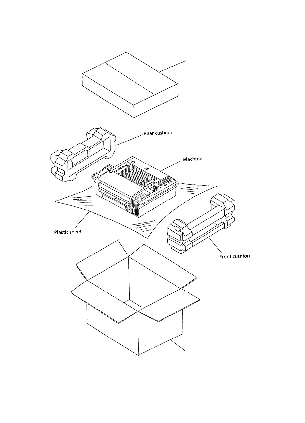
(3)
Take out the machine with plastic wrapper from the box.
3-2
Page 53
Accessory box
Figure 3.3.2
External carton box
Unpacking Procedure (2)
3-3
Page 54

Copy stacker
(In plastic bag)
Paper cassette
Document stacker
Toner cartridge and
Handset telephone
(In plastic bag)
’
(In plastic bag)
Figure 3.3.3
Partition board
Unpacking Procedure (3)
3-4
Page 55

3.4
Check of Contents
After having taken out the machine and accompanied accessories from the carton box,
check the contents according to the following list:
Table 3.4.1 Contents List
Item No.
1
2
3
4
5
6
7
8
9
10
1
OKIFAX
AC cord
Recording cassette
EP cartridge
Toner cartridge
Fuser pad
Handset telephone
Copy stacker
Document stacker
User’s guide
OF-150 facsimile
power
Name
paper
(A4
size)
1 Q’tv
1
1
1
1
1
1
1
1
1
1
vol.
Remarks
3-5
Page 56

3.5
installation of Attachments
(1) Items
-
Electra-photograph (EP) cartridge
-
Toner cartridge
*
Fuser pad
-
Recording paper cassette
-
Document and copy stackers
(2) Procedure
EP cartridge
1)
*
Push the scan unit release button to open the scan unit.
,Blue
EP
Figure 3.5.1
*
Push both blue knobs @ and open the LED head holder.
knobs
@
Figure 3.5.2
Cartridge installation (1)
EP
Cartridge Installation (2)
release button
LED head holder
3-6
Page 57

LED
*
Mount the EP cartridge in the printer unit. (See Figure 3.5.3)
Figure 3.5.3
Toner cartridge
2)
-
Take out the toner cartridge from the box, shake it five or six times as
shown in the illustration to eliminate the toner deflection, and peel off
the seal gently.
-
Insert the toner cartridge into the EP cartridge, making sure the fit
portions Q of the cartridge are in their proper places.
EP Cartridge Installation (3)
Figure 3.5.4
Toner Cartridge Installation (1)
3-7
Page 58

.
Using your thumbs, move the turn-knobs 0 on both sides of the cartridge
all the way back properly.
* The toner of the cartridge can come down to the EP cartridge.
Turn-knobs
@
Figure 3.5.5 Toner Cartridge Installation (2)
At this point, the turn-knobs should appear as shown in the figure below.
Turn-knobs
Toner cartridge
Figure 3.5.6
*
Clean the toner scattered in the vicinity of the toner cartridge using a
Toner Cartridge Installation (3)
cloth moistened with cold water. Do not use hot water since it makes the
toner fixed there.
*
Close the LED head holder of the printer unit until the blue knobs have
been locked completely.
3-8
Page 59

3)
Fuser pad
-
Take out the fuser pad from the plastic bag and set in the upper frame
-
Lower the left end in first, then the right end. Pull the pad slightly to the
right to lock it into place.
Fuser pad
Figure 3.5.7
-
Close the scan unit.
Fuser Pad Installation
3-9
Page 60

Red
line
Recording paper cassette
4)
Note:
About 200 sheets of paper can be set in the recording paper cassette.
Sheets must not exceed the red line of the paper limit indication. If the
excessive sheets are set, it will cause paper jams.
*
Set the recording paper (PPC) under the tabs of the recording paper
cassette.
Recording paper
Cassette cover
-
RecorGng
Figure 3.5.8
*
Insert the recording paper cassette into the machine.
Figure 3.5.9
Recording Paper Cassette Installation (1)
Recording Paper Cassette Installation (2)
paper cassette
3-10
Page 61

Document and copy stackers
5)
.
Hang the document and copy stackers onto hanging positions @J and
respectively.
@
Hanging positions
(Copy stacker)
0,
Figure 3.5.10 Document and Copy Stackers Installation (1)
Document stacker
Copy stacker
Figure 3.5.11
Document and Copy Stackers Installation (2)
3-
11
Page 62

3.6
AC Cord Connection
The power supply is provided as follows.
Nominal input voltage 230 VAC (Voltage range 198 to 264 VAC)
Check whether the voltage of your input is within the above-mentioned voltage range
and if so, check that the power switch is put OFF. In case of OFF switch, connect the
female plug of the AC cord to the machine and insert the male plug of the AC cord to
the inlet receptacle.
Turn the power switch ON and check that the display shows “(Date & Time)” standby
mode.
3.7
3.7.1
Initial Settings
Initial Settings by Serviceman
This section explains the setting items usually conducted
general users.
Table 3.7.1 shows the initial setting items and their purposes.
Figure 3.7.3 shows the general procedure of key operation.
The detailed procedures of the initial setting items will be explained on the following
pages.
Table 3.7.1 Initial Settings by Serviceman
(1)
Line monitor control
Changing the monitoring range.
Off-hook to DCN
Off-hook to
DIS
by a serviceman, not by
upon a communication
confirmation report upon a communication
from the opposite fax onto the received
picture.
the first page only.
TSI
is printed at the leading edge of
3-12
Page 63

tern
VO.
Name
Purpose
Default
(5) Continuous polling
(6) MH only
(7) Shorten protocol
(8) Call-back message
(9) Personal ID
Switching this function.
Effective for both the continuous polling
transmission and the continuous polling
reception.
Switching the function of limiting image
compression only to the MH code.
Switching the function of saving the whole
transmission time with the shortened
procedure.
Shorten protocols are short-cut protocol and
high-speed protocol.
Switching the function of sending, by fax, the
message requesting call-back contact in the
case that the remote station does not
respond to the voice request.
Switching the function of sending upper 16
characters of the sender ID as the personal ID.
The personal ID will appear in the remote
station’s display and in its activity report.
OFF
OFF
ON
ON
ON
(10) Relay broadcast initiate
(11) Confidential TX
(12) H-modem rate
(13) Ignoring the 1st
DIS
(14) Interval between CED
and
DIS
Switching the function of requesting relay
broadcast from the host fax with the relay
function. The former function is effective
only when the transfer password and the
remote list No. are registered.
Switching the confidential TX function.
Switching the modem’s starting speed,
9600 bps or 4800 bps.
Switching this function applicable to poor
circuit quality of overseas transmission, etc.
Selecting the interval of 75 ms or
1.5
sec.
The interval of 1.5 sec. is applicable to poor
circuit state of overseas transmission, etc.
ON
ON
9600 bps
OFF
75 ms
3-
13
Page 64

em
JO.
Name
Purpose
Default
(15) Protective tone against
the echo suppressor
(16) Manual TX CNG
(17) Manual RX CED
(18) Off-hook bypass
(19) Long document TX
(20) Attenuator
Switching the function applicable to poor
circuit state of overseas transmission, etc.
Switching the function of the CNG signal
from the transmitter in manual transmission.
Switching the function of transmitting the
CED signal from the receiver side in manual
reception.
Switching the function of maintaining
communication without hooking up the
telephone set in usual test, etc.
Switching the function of transmitting long-
size documents (more than 500 mm).
ON:
OFF:
Adjusting the attenuation
60 min.
500 mm
(de)
for the send
signal power level.
Adjusting value is 0 to 15 dB in one dB steps.
Since the basic send signal power level
of the OF-l 50 is 0
to - 15
dBm
in one
dBm,
you can select 0
dBm
steps for the send
(dBm)
dBm
signal power level.
OFF
ON
OFF
OFF
OFF
9dB
Note:
The send signal power level should meet your
country’s regulation. Some countries may
specify the input power level to a switching.
In that case, you should substruct the
specified level by the line cable attenuation
to determine the send level of your OF-l 50.
Figure 3.7.1 shows the non-loaded cable
attenuation.
3-14
Page 65

tern
No.
Name
Purpose
Default
21) Non-loaded (NL)
equalizer
(Compromized
equalizer)
122)
Document top feed
Determining the equalizing level of the
receiving signal.
0,4,8
and
12 d8 are
selectable.
Definition:
Equalizing level is difference of gains of
equalized signal between 0.3 KHz and
3.4 KHz.
Note:
By this adjustment you can give the inversed
characteristics to the internal equalizer
against the characteristics of the non-loaded
cable.
Figure 3.7.1 shows the characteristics of the
non-loaded cable.
Figure 3.7.2 shows the characteristics of the
internal equalizer.
Adjusting the paper edge where a document
is read at first.
Selectable: -7mmto
+lOmm
(1 mm steps)
JdB
3mm
;L;;E;‘direction
) F&y(;)
(
I
direction
0 0
u
Contact image sensor
3y
this, you can adjust
11)
the deviations caused by mechanical
12)
the effective reading area of a document.
tDocument
AV
PC2
photocoupler
parts, and
.
3-15
Page 66

tern
No.
Name
Purpose
Default
(23) Document end feed
Adjusting the paper end where a document is
read at last.
Selectable:
-1Ommto +lOmm
(1 mm steps)
See the figure shown in (22) for directions of
+ and
-.
By this, you can adjust
(1) the deviations caused by mechanical
parts, and
(2) the effective reading area of a document.
(24) Phone dial Switching alternate fax telephone number
(to be registered in the one-touch key) to
regular telephone number.
(25) Service bit
ON:
OFF:
Serviceman’s features are available.
Serviceman’s features are not
available.
0 mm
OFF
OFF
(26) Video parameter Selecting the non-photo mode parameter
(PI) and the photo mode parameter (P2) in
the form of Pl
*P2
to image sensing modes.
Refer to Table 3.7.2 and Table 3.7.3 for
further details.
(27) MDY/DMY Switching LCD display and report print from
month/day/year to day/month/year or vice
versa.
(28) CCITT ECM
Switching the function of the image signal
error correction method specified by CCITT.
(29) Receive in memory
Switching the RX memory function in the
following states: no paper, cover open,
paper jam, no toner
(30) Page retransmission
Switching the page retransmitting function
.
in case of memory transmission in non-ECM
mode.
1*1
D.M.Y.
ON
ON
ON
3-16
Page 67

tern
No.
Name
Purpose
Default
Local date and time
:311
print
XTTO value
:32)
Enables or disables the function of printing
local date and time at the top of the first
received page.
Registers the time duration (in seconds) for
which OF-1 50 waits for the remote station’s
answer. This timer starts when the last dial
digit has been sent in the automatic
transmission mode. As a special case, when
000 selected, the following predetermined
values will be used according to PTT
parameters:
OFF
300
Receive in memory in no
:331
toner state
RX error message print
134)
MMR
(35)
75% reduction
(3’3)
Print counter on LCD in
(37)
the standby mode
Sets whether to print the received message or
to receive the message in the memory when
the remaining toner level is low or none.
Enables or disables the function of printing
“*
the message
RECEIVE STOPPED *” when
reception of one page is interrupted halfway
because the remote station’s STOP key is
pressed, its document is jammed or line
condition is poor.
Enables or disables the MMR communication.
The 75% reduction feature is functionally
unused.
Switches the function of displaying the print
counter on LCD in the standby mode.
ON
ON
ON
ON
OFF
3-17
Page 68

item
No.
2
Ring response time
Name
Purpose
This feature can access by setting service bit.
1 ring7571 O/l
5/20/25/30 sec.
Default
1 ring
3 TSI
4
Dial parameter
(1) PTT parameter
(2) Redial tries
(3) Redial interval
(4)
Busy tone detect
(5)
MFor
(6) DP rate
(7)
DP make ratio
(8)
DP dial type
DP
Registration of
TSVCSI
Selecting the following parameters:
INT’L, GRB,
SUI, AUT, ESP,
NOR,SWE,AUS,
ITA,
GRE
USA, BEL, HOL,
0 to 10 tries (one try steps)
1 to 6 minutes (one minute steps)
ON/OFF
1
O/l
6 pps
33%/39%
Normal/l 0 - N/N + 1
Blank
INT’L
2 tries
3 min.
ON
MF
10 PPs
39%
Normal
(9) MF duration
(10) PBX line
(11) Access digit
(12) Flash/Earth/Normal
(13)
Dial tone detect
(14) Auto start
75/85/l 00 ms
ON/OFF
OFF/Digit(s)
F/E/N (PBX line origination types)
ON/OFF
ON/OFF
100 ms
OFF
OFF
Normal
ON
OFF
3-18
Page 69

3.7.2
Initial Settings by User
This section explains the items usually set up by general users.
Table 3.7.4 shows the initial setting items and their purposes.
Figure 3.7.3 shows the general procedure of key operation.
The detailed procedure of the initial setting items will be explained on the following
pages.
Table 3.7.4 initial Settings by User
tern
VO.
Ine
touch key program
Name
-wo-digit auto dial program
Purpose
Telephone one touch keys permit
registering:
Telephone number (numeral, -, P, and
(1)
space) in 32 digits.
Alternate telephone number in 32 digits
(2)
(additional registration)
ID for the telephone directory function in
(3)
15 characters (alphabets, numeral, and
symbols).
(One ID can be registered for one key).
Auto dial No. 01 to 30 allow registering
telephone number in 32 digits (numeral, -, P,
and space) and ID for the telephone directory
function in 15 characters (alphabets,
numeral, and symbols).
Auto dial No. 31 to 70 allow registering only
telephone number in 20 digits. (The tele-
phone directory function is not available
because ID registration is not permitted.)
Default
llank
llank
3roup
setting
Grouping some one-touch keys and some
two-digit auto dial codes to which telephone
numbers have been assigned.
This group setting makes multiple polling
reception and broadcast operation simple.
3-37
JO
v-Ow
egi-
tered.
Page 70

tern
VO.
Function program
4
Name
(1) Message confirmation
report (Signal location)
Purpose
To enable/disable the automatic message
confirmation printout after a single location
call.
Default
OFF
(2) Message confirmation
report (Multiple
locations)
(3)
Activity report full
printout
To enable/disable the automatic printout of
the multiple polling reception and the
broadcast.
To enable/disable the automatic printout of
the activity report when 30 communications
have been recorded in the interval memory.
(4)
Absent mode auto-timer To specify the time when the reception mode
will be changed from the manual receive
mode to the auto receive mode.
To disable this function (OFF).
(5)
Line monitor volume
To control the volume.
OFF/Low/High selectable.
(6) Remote diagnosis
To enable/disable the access to your OF-l 50
from the remote center for diagnosis.
(7) Sender ID
To position the sender ID, inside (IN) or
outside (OUT) the copied document area.
To disable the sender ID function (OFF).
OFF
OFF
OFF
LOW
OFF
OUT
(8) Closed network
To enable/disable
(a)
The access to your OF-l 50 from stations
which are not registered in one-touch key
or two-digit auto dial code.
(b) The access from your OF-l 50 to stations
which are not registered in one-touch key
or two-digit code.
OFF/RX only/TX and RX selectable.
3 - 38
OFF
Page 71

tern
No.
Name
Purpose
Default
9) TX mode default
10) Telephone/fax
automatic switchover
timer
11) No paper call
12) RX reduction printing
To select the mode automatically set up
Nhen
a document is loaded in the feeder.
The
following combinations are selectable.
STD/NORMAL-STD/DARK-STD/
LIGHT-FINE/NORMAL-FINE/DARK-FINE/
LIGHT-PHOTO/NORMAL-PHOTO/
DARK-PHOTO/LIGHT
To specify the time for which the OF-l 50
alerts
you on reception of a call in the
:elephone/fax automatic switchover mode.
20 sec./35 sec. selectable
To
enable or disable the function to alert
Jpon
the no paper state.
jpecifies
document
;ize
*atio<
whether to print a received
longer than the recording paper
with scale reduction
(900/, 5
reduction
100%) or to print it in the original size
Nithout scale reduction.
;TD/
JORMAL
!O sec.
IFF
IN
13) Copy reduction printing
14) RX split printing
15) Copy split printing
jpecifies
:han
.eduction
:o
whether to copy a document longer
the recording paper size with scale
(90% S reduction ratio< 100%) or
print it in the original size without scale
.eduction.
jpecifies
document
;ize
3arts
whether to print a received
longer than the recording paper
with splitting into the upper and lower
of the document or to print it only for
:he portion covered by one recording paper
;heet
without splitting.
jpecifies
whether to copy a received
document longer than the recording paper
size with splitting into the upper and lower
parts of the document or to copy it only for
the portion covered by one recording paper
sheet without splitting.
IN
IN
IN
3-39
Page 72

tern
No.
Name
Purpose
Default
(16) Buzzer volume
(17) Message confirmation
display or printing
(18) Confidential RX report
(19) Ring responsetime
To select the sound volume of each of the key
touch tone, end of communication buzzer
and voice request buzzer from the high, low
and midle levels.
Registers the LCD display or report whichever
is selected as the method for checking the
result of the last call.
Registers whether automatic output of the
cinfidential RX report is or is not needed after
receiving a confidential call.
User can register ring response time if PTT
parameter is:
INT’L, GBR, NOR, SWE, USA, ESP,
ITA
or
GRE
See Page 3-33 for the operation.
MID.
DISP.
ON
1
ring
(20) One-touch keys
parameter
Clock adjustment
5
6
System data program
Dial parameter
7
To assign the follwing features to each
one-
touch key.
(a) Starting modem rate (9600/4800 bps)
(b) Protective tone (ON/OFF)
ignoring the 1 st
DIS.
(c) MH only (ON/OFF)
Date and time adjustment
(a) Registration of
TSVCSI
except for BEL,
SUI
and AUT.
(b) Registration of sender ID.
(c) Registration of telephone number for the
call-back message.
(a) User can register access digit of PBX.
(b) Depending on PTT parameter, user may
register redial tries and redial interval.
Redial tries:
INT’L, NOR, SWE, USA,
HOL,
ITA
9600 bps
OFF
OFF
Blank
Blank
Blank
Access
digit:OF
2 times
3-40
Page 73

tern
No.
Name
Purpose
Default
Programming password
8
Redial interval: INT’L, NOR, SWE, USA,
HOL,
ITA
MF or DP:
INT’L, GBR, NOR, SWE,
AUS, USA, HOL, ESP, ITA,
GRE
PBX line:
INT’L, NOR, SWE, USA,
HOL, ESP,
ITA
Flash/Earth/
Normal
Auto start:
:
NOR,
ITA
INT’L, GBR, NOR, SWE,
AUS, USA, BEL, HOL, ESP,
ITA, G RE
To allow the operator (in this case, the person
who wishes to assign a password to mail-box)
to assign a 4-digit password code to one of 16
mail-box memory segments in the message
memory.
3 min.
VlF
3FF
u
3FF
3-41
Page 74

1.
One touch key program
Operations:
To get the right message, press SELECT
l
FUNCTION key once and
standby mode. (In case of non-message in
memory)
l
Press
q
key.
q
key twice in the
The display shows:
USER PROGRAM?
YES(+/l-6)
NO(+)
“b
To 1: ONE TOUCH KEY PRGRAM
3-42
Page 75

l:ONE TOUCH KEY PRG?
YES(ONE TOUCH)NO(+)
@NO=< OR LOCATION >
3SEC
@
NO=
ID=-
G'NO=03-404-7321
ID=
D N0=03-404-7321
ID=
-
DNO=03-404-732
ID=6
D;&;3-404-7321
-
blSPLAY
03...1..1
(Example)
-
START
-
6 (Example)
I
1
6 (Example)
I
6 (Example)
3;EC
[)NO;_
03...:..5 (Example)
DNO=O3-404-7325_
START
1
E
DNO=03-404-7321
ID=N
3 (Example)
@NO=03-404-7321
ID=Nj
. . . . . . .
@NO=03-404-7321
ID=NEWYORK OFFICE
START
CL
This flowchart shows the case that the phone dial setting of technical function is OFF.
3-43
Page 76

I@
NO=<
.I
@
NO=
DNO=03-404-7321
OT#l
I
f
FAX NO.
3SEC DISPLAY
-
03...!..1
I
>
(Example)
-
23
NO=<
TEL NO.
ID=< LOCATION ID
3sk
13
NO=_
ID=
I
nNO=03-404-7325_
ID=
I
03...:..5
(Example)
I
>
>
I
START
-7
nNO=03-404-7321_
ID=
-
nNO=03-404-7321
ID=6
nNO=Oj-404-7321
ID=M
nNO=O3-404-7321
ID=Nz
. . . . . . .
I
16
(Example)
6 (Example)
I
6 (Example)
I
I
mN0=03-404-7321
ID=NEWYORK OFFICE
This flowchart shows the case that the phone dial setting of technical function is ON.
3-44
Page 77

2.
Two-digit auto dial program
Operations:
0
To get the right message, press SELECT
FUNCTION key once and fl key twice in the
standby mode. (In case of non-message in
memory)
l
Enter 2 by the ten-key pad.
The display shows:
USER PROGRAM?
YES(+/l-6) NO(+)
111
!(
To 2: AUTO DIAL PROGRAM
3-45
Page 78

Operations:
The display shows:
2:AUT0 DIAL PROGRAM?
YES(A/D) NO(Jl-6)
LOCATION No. 31 to No. 70
i
NO=< FAX NO.
3SEC DISPLAY
I
AAUTO
AUTO DIAL NO. ? I_
ENTER 01-70
1
AUTO DIAL NO. ?
ENTER 01-70
I 1
NO=
<
>
ID=< LOCATION ID >
FAX NO. >
3SEC
IhSPLAY
0
DIAL key
1
[O_]
_
I
/F;-
03......
03-123
1
G
“’
p++
+,
6
1
NO=Oj-40d-7321
ID=tj
6
1
N0=03-404-7321
ID+
L
START key
3-46
Page 79

3.
Group settimg
Operations:
To get the right message, press SELECT
0
FUNCTION key once and
standby mode. (In case of non-message in
memory)
Enter 3 by the ten-key pad.
l
l
Press
q
To select the group number, press the number
l
key or repeat pressing
number appears on LCD, then press
key.
q
q
key twice in the
key until the group
q
key.
The display shows:
USER PROGRAM?
I
1 YES(+/l-6)
NO(+)
”
3:GROUP SETTING?
YES(+)
El
l:#lGROUP
YES(+)
NO(-/l-6)
\(
SETTING?
NO(-./l-5)
I
q
3-47
4:#4GROUP
YES(+)
5:85GROUP
YES(+)
e
0
To the next page
SETTING?
NO(Jl-5)
SETTING?
NO(+/l-5)
izl
v
Fl-111
q
*Q
Page 80

Case
1:
Making
a group
l
Press one-touch key or Auto Dial key followed
by two digit code which you want to put into
the group.
l
Press
q
key to cancel it.
l
Repeat the above operation until all locations
you want are registered.
l
To finalize grouping, press
key.
key to register the location or
q
key or STOP
q
I
I
(One-touch key)
or
(A/D code)
I
I
or
@
(Location ID.)
YES(+)
NO(+/LOC.)
END
3-48
Page 81

Case 2:
Cancelling member(s) from a group
0
Press
q
l
Press
group or
l
Repeat the above operation until all members
you want to cancel displayed.
key.
q
q
key to keep the location in the
key to cancel it.
i=lto5
@
(Phone No.)
YES(-)
@
(Location ID)
YES(+)
J
NO(+/LOC.)
or
NO(+/LOC.)
l
To finalize cancellation, press
key.
q
key or STOP
3-49
Page 82

Function program
4.
Operations:
l
To get the right message, press SELECT
FUNCTION key once and
standby mode. (in case of non-message in
memory)
l
Enter 4 by the ten-key pad.
q
key twice in the
The display shows:
USER PROGRAM?
YES(+/l-6) NO(+)
lzl
v
To 4: FUNCTION PROGRAM
3-50
Page 83

Operations:
02_
02:MCT (MUTI-LOC.]?
[
OFF J
')4c 04:AUTO-REC
[ OFF 1
YES(-) NO(-)
I
TIMER?
YES(-)
NO(-) ; [_ :
The display shows:
Continuued from the previous page.
I
~:FUNCTION PROGRAM?
YES(-)
NO(-/l-6)
10
FUNCTION NO.? [_
ENTER
01-19
]
o-9
l-7
I 1
fl PRG. START TIME
IENTER 4DICITS
‘1
lo:*;:
j
[20SEC1
To RX REDUCTION
TIMER PRG?
YES(-)
NO(-)
[35SEC], [20SEC]
q
05 05:MONITOR VOLUME?
- [
OFF ]
06 06:REMOTE DIAG.?
-
[ OFF ] YES(-)
I
07_
07:SENDER
[
OUT ]
YES(-) NO(-)
NO(-)
ID?
YES(-) No(-)
04:AUTO-REC
[12:33]
TIMER?
YES(-)
NO(-)
[OFF], [ L I, [ H
[T/R],[RK],
[OFF1
4DlGlT
I
NOTE:
l * denotes that function
LCD display will
instead of
service
19,
bit is ON.
become
when the
20
8
t”
FLASHING LED WILL BE MOVED BY
STD/NORMAL~STD/DARK-STD/LIGHT-FINE/NORMAL-FINE/DARK-FINE/LIGHT
3-51
EVERYH
KEY.
PHOTO/LIGHT.-PHOTO/DARK-PHOTO/NORMAL
7
Page 84

Continued fromthepreviouspage.
+
I2
12:RX REDUCTION?
-
[ ON ]
YES(t),NO(+)
WI
I3
13:COPY REDUCTION?
-
[ OFF ] YES(-) NO(+)
tn
l4 14:RX
-
l6
16:BUZZER VOLUME?
-
SPLIT PRINT?
[ ON ] YES(t) NO(+)
[MID.] YES(+) NO(+)
[MID.
DISP.l,[PRINT]
[:
l,[HIGHl,[LOW]
I
18:CONF.RX
[
ON
I
One-touch key pressed.
REPORT?
]
YES(+) NO(+)
ECHO PROTECTION?
[ X
]
YES(c) NO(+)
b
MH ONLY?
[ X
]
YES(+) NO(+)
I
Setting (Toggle)
X:
Setting (Toggle)
X:
OFFSON
\m
OFF%ON
3 - 52
Page 85

5.
Clock adjustment
Operations:
To get the right message, press
0
FUNCTION
standby mode. (In case of non-message in
memory)
Enter 5 by the ten-key pad.
l
l Press lfIJ key.
l
Press
q
key once and
key.
SELECT
q
key twice in the
The display shows:
I-T-J
l.CLOCK
YES(+) NO(-/I-3)
/I
J-
ADJUSTMENT?
I’
[Q?/25/89 12:331
YES(e)
NO(+/O-9)
-+
ORO-9
*
q
3 - 54
Page 86

6.
System data program
-
TSKSI (User can register it when PTT parameter is
-
Registration of sender ID
-
Registration of telephone number for the call-back message
AUS,
USA, HOL, ESP,
ITA
or GRE)
INT’L,
GBR, NOR, SWE,
Operations:
l
To get the right message, press
SELECT FUNCTION key once and
key twice in the standby mode. (In
case of non-message in memory)
,e
Enter 5 by the ten-key pad.
l Press
0
Press
0
Press
!d
key.
q
key.
q
key.
q
The display shows:
5 : DATA PROGRAM?
YES(-)
l:CLOCK ADJUSTMENT?
YES(+)
2:SYSTEM DATA PRG.?
YES(-)
@
NO=<
NO(+/l-6)
NO(-/I-3)
NO(-/l-3)
TSI/CSI
ID=< SENDER ID >
>
El
Note:
Use the UNIQUE
key
BEL,
SUI
or AUT)
to
input special symbols.
3 SEC ‘AFTER
(INT’L, GBR, NOR,
etc.)
@
NO=0495 21 4921
NUMERAL
To the next page
KEY + q
+
3 - 55
Page 87

Operations:
The display shows:
Continued from the previous page.
@NO=0495 21 4921
ID=OKI
I-
O
START
!f
7
I~N~=<~BM. TEL No.>
I
I
I
3SEC AFTER
I
I
I
@NO=0495 22
5111_
START
v
END
3-56
Page 88

7.
Dial parameter
Users may be able to register the following items depending on PTT parameters:
*
Redial tries
-
Redial interval
- MForDP
-
PBXline
*
Access digit of PBX
-
Flash/Earth/Normal
-
Auto start
To get the “DIAL PARAMETER?” message on the display, perform the same
operation as Item 4 of 3.7.1,
Available for INT’L, NOR, SWE, USA, HOL and
“0
TRY” to
Available
“1 MIN” to “6 MIN”
Available for INT’L, GBR, NOR, SWE,
ESP,
,aMF”
Available for INT’L, NOR, SWE, USA, HOL, ESP and
ITA.
“OFF” or “ON”
IN CASE of 4 “SPACE“
*
Available for NOR
and
ITA.
#nF”
or
for
ITA
and GRE.
or
uDP”
#nE”
or
“IO
TRY”
INT’L, NOR, SWE, USA, HOL and
AUS,
1 I
O-9 or SPACE
p+Eg
,nN”
I
ITA.
ITA.
USA, HOL,
-I
El El
Available for INT’L, GBR, NOR, SWE,
HOL, ESP,
“OFF” or “ON”
ITA
and GRE.
AUS,
USA, BEL,
3-57
Page 89

8.
Programming password
Operations:
To get the
0
FUNCTION key once and
standby
mode. (Incaseofnon-messagein
right message, press SELECT
q
key twice in the
memory)
l
Enter6bytheten-keypad.
l
Press
q
l
Enter2digit(Olto16)bytheten_keypad.
key.
The display shows:
USER PROGRAM?
YES(+/l-6)
NO(+)
Fl
‘I
6:PROGRAM PASSWORD?
YES(+)
H
NO(*/l-6) -
H
r
MAIL BOX NO.
PASSWORD
=[_ ]
=[._
1
-
+
Enter 4 digit by the ten-key pad.
l
MAIL BOX NO.
PASSWORD
=[02]
=[I2341
3-58
Page 90

3.8
Off-line Tests
(1)
Items_
Self-diagnosis test
I)
*
Test print
.
ROMs check
* RAMS
Local copying test
2)
(2) Procedure
Self-diagnosis test
1)
check
Operations:
l
To get the right message, press SELECT
FUNCTION key once and COPY key twice in
the standby mode. (In case of non-message in
memory)
l
Press
q
l
Press
q
l
Press
q
l
Press
(The printed data is shown in Figure 3.8.1.)
key.
key.
key.
q
key
for checking and test printing.
The display shows:
T--
1: LOCAL TEST?
YES(-)
II:
SELF DIAGNOSIS?
1
ES(+)
1: LOCAL TEST?
:;-)
;
1: SELF DIAGNOSIS
NO(+/l-3)
"07-8)
NO(r-3'
CHECKING
Local copy test
2)
*
1: SELF DIAGNOSIS
PRINTING
Set documents in the feeder, and press COPY key.
3 - 59
Page 91

RON 1L
RON 1U
RON
VERSION 104
RRN
1 OK
RFlN
2
RFlN
3
RFIN
4
RFlN
5
RQN
6
RRN
7
PIF RON
PIF
RGN
OK
OK
OK
OK
OK
OK
OK
OK
OK
OK
C702
5981
= 00000
TX
RX = 00000
RQM8
rwrl9
ml18
Rcdlll
RQrll2
ml13
.RGy14
RQMlS
OK
OK
OK
OK
OK
OK
OK
OK
RWl 16
Rml
17
RWI 18
Rm
19
Rma
Rm
21
Rwl22
RCUI
23
OK
OK
OK
OK
OK
OK
OK
OK
Printed if MEM30 board is mounted.
Fig. 3.8.1
Printed Data of Self-diagnosis Test Print
3-60
Page 92

3.9
Tel,ephone
(1)
Procedure
*
Connect the lines.
and Line Connections
Fig. 3.9.1
Telephone and Line Connections
3-61
Page 93

3.10
On-line Tests
3.10.1 Transmission
Load documents
(1)
Make sure that
(2)
*,
The loaded documents are inserted automatically.
-
The STD and NORMAL lamps light.
-
The display shows “SELECT LOCATION.”
Dial the telephone number of the remote machine by the ten-key pad.
(3)
Make sure that the telephone number of the remote machine is shown on the
(4)
display.
Press the START button.
(5)
Typical message transmission is described in Figure 3.10.1.
(6)
3.10.2
Reception
(1)
Use another machine for dialling.
(2)
Make sure that
*
The display shows “AUTO REC. START”.
.
The message is automatically received.
(3) Typical message reception is described in Figure 3.10.2.
3 - 62
Page 94

1 Xx/xx/;y xX:xX 1
YES
(STANDBY CONDITION)
(.
LOAD DOCUMENT(S), SELECT RESOLUTION MODE)
MANUAL SEND MODE
NO
. OFF HOOK
. MANUAL DIALLING
ONE-TOUCH
. ONE-TOUCH KEY
(e.g. No. 1)
l PRESS “AUTO DIAL” KEY
l SET THE CODE (e.g. 01)
DIALING
CALLING
NO
4542111
1
4542111
+
KEYPAD DIAL
l ENTER DIGITS
YES
l PRESS
“START” KEY
NO
SENDIN:54/‘db ’
I
EXAMPLES
COVER OPEN
DOG. JAMMED
I
I
A (.
FAX MESSAGE TRANSMISSION STATUS)
NO
YES
I
, or
, etc.
3 454
SENDING
I
TRANSMISSION
RESULT = OK
xx/xx/xx xx:xx
2111
+
F
t‘
/96
I
YES
COMMUN. ERROR
(*ABOUT
(*STANDBY CONDITION)
i
SEC.)
1
Fig. 3.10.1
Typical Message Transmission
3 - 63
Page 95

. RINGING
DETECTED
AUTO
YES
REC. START
I
NO
xx/xx/xx xx:xx
I
MANUAL RX START
YES
. FAX MESSAGE RECEPTION
STATUS
(*STANDBY
NO
CONDITION)
MANUAL RECEIVE MODE
. OFF-HOOK AND CONVERSATION
l PRESS “START” BUTTON
‘r
>
Fig. 3.10.2
1
COMMUN
(~STANDBY coNDITtoN)
Typical Message Reception
3 - 64
1
ERROR
Page 96

Page 97

Page 98

Page 99

Page 100

 Loading...