

North Star DIMENSION Service Manual
North
Star
DIMENSIONTM
Service Manual

•.nr^
...^s
NOTICE
North Star Computers
,
Inc. makes no representations or warranties with
respect to this manual
.
Further, North Star Computers
,
Inc. reserves the
right to make changes in the specifications of the product described in
,^ this manual at any time without notice and without obligation of North
Star Computers
,
Inc. to notify any person of such revision or changes. All
technical information
,
statements and recommendations in this document
and in any manuals or related documents are believed to be reliable, but
the accuracy or completeness thereof is not guaranteed.
DISCLAIMER
OF WARRANTY
North Star Computers
,
Inc. makes no representations or warranties
,
either
expressed or implied
,
by or with respect to hardware, software, or
anything in this manual
,
and shall not be liable for any implied warranties
of merchantability or fitness for a particular purpose or for any indirect,
special or consequential damages
.
Some states do not allow the exclusion
of incidental or consequential damages, so this exclusion may not apply to
you.
COPYRIGHT NOTICE
All rights reserved
.
No part of this publication may be reproduced
,
stored
in a retieval system, or transmitted
,
in any form or by any means,
mechanical
,
photocopying
,
recording or otherwise
,
without the prior written
consent of North Star Computers
,
Inc. No patent liability is assumed with
respect to the use of the information
'
contained herein
.
While every
precaution has been taken in the preparation of this manual, North Star
Computers
,
Inc. assumes no responsibility for errors or omissions.
Furthermore
,
this publication and features described herein, are subject to
change without notice.
DIMENSION
Service Manual i
TRADEMARKS
c North
Star
DIMENSION
is a trademark
of North Star Computers, Inc.
North
Star
NetWare is
a trademark
of North Star Computers, Inc.
NetWare
is a trademark
of Novell Inc.
MS-DOS is a trademark of Microsoft Corporation.
IBM, IBM PC, and IBM XT are registered trademarks of International
Business
Machines
^t 80186
,
8254
, 2732A, 2764,
8274, 8255A-5 and 8259A are registered
trademarks of Intel Corporation
SCN2682 is a trademark of Signetics Corporation
uPD765A
is a trademark
of NEC Electronics USA Incorporated
WDIO10-00/01 is a trademark of Western Digital Corporation
ti MC6845 and MC146818 are trademarks of Motorola Semiconductor
Products
Copyright 1985 by North Star Computers, Inc.
All rights reserved.
FEDERAL COMMUNICATIONS COMMISSION
RADIO FREQUENCY INTERFERENCE STATEMENT
Warning: This equipment has been certified to comply with the limits for a
Class A computing device
,
persuant to Subpart J of Part 15
of FCC rules.
Only peripheral devices
(
computer devices, terminals
,
printers, etc.)
certified to comply with the Class B limits may be attached to this
computer
.
Operation with non-certified peripheral devices may result in
interference to radio and television reception.
ii DIMENSION Service Manual
Instructions
To Users: This equipment generates and uses radio frequency
energy and if not installed and used properly
, i.e., in
strict accordance
with the operating instructions and reference manuals, may cause
interference to radio and television reception.
,,.•., If this equipment does cause interference to radio or television reception,
the user is encouraged to try to correct the problem by employing one or
more of the following measures:
0400-
r Reorient the receiving antenna.
• Relocate the equipment with respect to the receiver.
* Move the equipment away from the receiver.
* Plug the equipment into a different electrical outlet so that the
equipment and receiver are on different branch circuits.
* Ensure that workstation circuit board mounting screws, peripheral
device attachment screws, and ground wires are properly fastened.
* Ensure that workstation circuit board sheet-metal covers are in
place when no workstation circuit boards are installed.
If necessary, consult your dealer for additional suggestions.
North Star Computers, Inc. is not responsible for radio or television
interference caused by unauthorized modifications to this equipment. It is
the responsibility of the user to correct such interference.
Caution
: This equipment is equipped with a UL listed and CSA certified
plug. It is to be used in conjunction with a properly grounded, 115VAC
receptacle to avoid electrical shock.
DIMENSION
Service Manual iii
iv DIMENSION Service Manual
INTRODUCTION TO THE
DIMENSION
SERVICE MANUAL
The North Star DIMENSION is a versatile, fast, and reliable computer
system that incorporates contemporary system design, imaginative use of
electronic circuitry and components, and rigid manufacturing quality
control. This service manual attempts to follow in these traditions.
A service manual that attempts to be all things to all people is asking for
trouble. There are computer users who simply want to install their own
systems; technicians who have only the responsibility of maintaining the
equipment; engineers who need to understand the host-system in order to
design hardware peripherals; and programmers who may wish to create
alternative operating systems or application packages. This manual is not
written for all of you.
If you are a system owner
/
user who wants to install your own equipment,
we recommend reading the
DIMENSION
System Manual. It contains
abbreviated hardware and operating system installation instructions that
are tailored especially for you.
If you are a technician who needs a manual to help speed your
troubleshooting, diagnosis, and repair of problems, this manual is for you.
The manual is specifically designed for the field technician who must get
in, fix the problem, and leave quickly. The manual contains no theories of
operation, specifications, extensive parts lists or schematics. It does
contain diagnostic charts, troubleshooting steps, and
removal/replacement/adjustment procedures. The DIMENSION Service
Manual is the field-accompaniment to the DIMENSION Technical Manual.
If you are an engineer who needs to know anything and everything about
DIMENSION
hardware, we recommend
that you refer to the DIMENSION
Technical
Manual
.
It contains specifications
,
theories of operation,
schematic diagrams
,
timing diagrams
,
and parts lists related to the system
and each of its components.
If you are a programmer
,
and your task is to create alternative operating
systems or application programs for our computer
,
we recommend reading
the DIMENSION Programmer's Notebook
.
This manual contains only the
very specialized information required by a programmer.
DIMENSION
Service Manual v
INTRODUCTION TO THE DIMENSION SERVICE MANUAL (cont.)
If you are still in doubt about the appropriateness of this manual to your
area of interest, refer to the following paragraphs for a more in-depth
discussion of the contents of the North Star DIMENSION Service Manual.
Chapter 1 - Hardware
Installation
discusses procedures used for installing
all system hardware. This includes installation procedures for the
central module and workstations as well as procedures and
requirements for attaching shared and local printers, modems and
local mouse devices.
Chapter 2 - Troubleshooting discusses the processes used for locating
faults within the DIMENSION system. The chapter is comprised of
in-depth discussions about the auto-boot diagnostic aid and power
supply and central board troubleshooting procedures. An expanded
troubleshooting chart that covers both hardware and software
symptoms is also included.
Chapter 3 -
Diagnostics
discusses the four diagnostic aids that are
provided with the DIMENSION system. These include:
r Self tests that checks critical central module hardware
x^ Service Diskette #1 that provides a further test of central module
hardware
^t Service Diskette #2 that tests and formats the diskette and fixed
disk drives
^Y Service Diskette #3 that tests and evaluates the tape drive
system
Chapter
4 - Subassembly Removal
provides procedures used for removing
all system hardware. The chapter is a shorthand device that
explains in a concise manner all the steps necessary to remove any
major subassembly from the central module.
Appendix A - Parts Lists contains parts lists for system subassemblies.
Appendix B - I/O Ports
contains information about the four DIMENSION
I/O ports.
vi DIMENSION Service Manual
DIMENSION SERVICE MANUAL TABLE OF CONTENTS
INTRODUCTION TO THE DIMENSION SERVICE MANUAL
CHAPTER 1 - HARDWARE INSTALLATION
Physical Location of the System Modules
Central Module Installation and Configuration
Opening the Central Module
Central Board Expansion RAM Installation
Workstation Board Expansion RAM Installation
8087 Board Installation
Workstation Board Installation
OMNINET Board
Installation
Tape Drive and Tape Drive Interface Board Installation
Second Fixed Disk Drive Installation
Checking the Power Supply
Checking the Selectable Power Line Receptacle
Central Module Final Setup
Workstation
Installation
Workstation
Installation
Tilt and Swivel Installation
Shared Printer Installation
Shared Parallel Printer Installation
Shared Serial Printer Installation
Local Printer Installation
Local Modem
Installation
Local Mouse
Installation
CHAPTER 2 - TROUBLESHOOTING
Auto-Boot Diagnostics
Preliminary Troubleshooting (Boot Sequence)
v
1-2
1-5
1-7
1-8
1-10
1-12
1-15
1-17
1-19
1-25
1-31
1-33
1-37
1-39
1-40
1-43
1-45
1-47
1-48
1-49
1-53
1-56
2-2
2-2
DIMENSION
Service Manual vii
TABLE OF CONTENTS (
cont.)
System Troubleshooting
Boot Problems
Hang Problems
Printer Problems
Printer Problems in MAINT
Application Installation Problems
Asynchronous Communications Problems
TPA (Workstation Memory
)
Problems
dBase II Problems
Miscellaneous Application Problems
Fixed Disk Problems
Monitor Problems
Keyboard Problems
Miscellaneous Problems
Tape Drive Problems
Testing the Central Module Power Supply
Power Supply Troubleshooting Chart
Testing the Central Board
CHAPTER 3
-
DIAGNOSTICS
Supplemental Tools
Self-tests
Service Diskettes
Loading Service Diskettes
Service Diskette #1
Test Options
Test Data Pointer Screen
Central Board Test Analysis Screen
Workstation Board Test Failure Screen
Communications Port Testing
2-6
2-7
2-19
2-22
2-28
2-30
2-33
2-35
2-37
2-39
2-42
2-47
2-49
2-51
2-55
2-57
2-59
2-63
3-2
3-3
3-5
3-6
3-7
3-10
3-13
3-14
3-15
3-16
Iftow
viii DIMENSION Service Manual
(cont.) TABLE OF CONTENTS
Service Diskette #2
3-17
Test Options
3-18
Diskette Drive Test
3-23
Fixed Disk Format and Label Writer
3-25
Test Fixed Disk Drives
3-26
Park Fixed Disk Drive Heads
3-28
Using Fixed Disk Drive Extension Cables
3-29
Error Screens and Codes
3-31
Error Code Matrix
3-39
Service Diskette #3
3-45
Loading Service Diskette #3
3-46
Tape
Diagnostic
Main Menu
3-48
Test Options
3-49
Technician Menu
3-52
Test Options
3-53
Interpreting
Drive Status Bytes
3-58
Error
Message Interpretation
3-59
CHAPTER 4 - SUBASSEMBLY REMOVAL
Workstation Board
4-3
8087 Board
4-4
OMNINET Board
4-5
Tape Drive
Interface Board
4-6
Workstation 128K/384K
Expansion
RAM Board
4-7
Power Supply
4-8
Central Board Expansion RAM
4-10
Bus Board
4-1 1
Central Board
4-12
Diskette Drive
4-14
Fixed Disk Drive
4-16
Tape Drive
4-17
Installing
a New
Central Board
4-19
Installing a New Bus Board
4-21
DIMENSION
Service Manual ix
TABLE OF CONTENTS
(
cont.)
APPENDIX A - PARTS LISTS
Central Module
A-2
Miscellaneous Parts
A-2
Circuit Boards
A-4
Harnesses and Cables
A-5
Workstation
A-6
Miscellaneous Workstation Parts
A-6
APPENDIX
B - I/O PORTS
Serial Ports Si and S2
Serial Port Pinouts
Parallel Port P1
Parallel Port Pinouts
Workstation Interconnect Box Serial Port
Serial Port Pinouts
B-2
B-3
B-5
B-6
B-8 ....^
B-8
x DIMENSION
Service Manual
CHAPTER 1
HARDWAREINSTALLATION
Overview
This chapter explains how to install DIMENSION
computer system hardware including the central
module, its workstations and peripheral devices
such as printers.
DIMENSION computer systems may vary significantly
in complexity. A simple system might contain two
workstations and' a shared printer; a complex sys-
tem might contain as many as-twelve-workstations
with shared and local printers and modems, and
local mouse devices. Simple and complex systems
use the installation procedures found on the
following pages.
Because of the number of power cords and cables
used to connect the components of the system, you
should position the equipment before attaching
cords and cables. Begin the installation by
sketching your office area and determining where
you plan to locate the central module, worksta-
tions and peripheral equipment. Then unpack and
move the components to the locations suggested by
your sketch. After you've finished positioning
the equipment, begin using the installation
procedures to connect the components.
You'll need a small slotted
screwdriver and a
medium Phillips screwdriver to complete the
installation
procedures.
Technical Manual 1-1
SYSTEM HARDWARE INSTALLATION
Physical Location of the System Modules
General
Before you begin positioning the components of
Requirements
your computer system, consider the following
requirements:
o The central module and the video displays
receive their power from standard 115VAC (U.S.)
or 230VAC (international) three-conductor,
grounded power outlets.
The central module and any peripheral devices
attached to the central module must share power
outlets that are part of a commonly fused and
grounded electric circuit.
o The length of the central module and video
display power cables is fixed, so placement of
these components is determined by power cable
length and power outlet location. You may be
able to install three-conductor, grounded
extension cords if they are rated for at least
10 amps (115VAC) or 5 amps (230VAC).
o A standard workstation cable is 25 feet long;
100-foot extensions are also available. Three
100-foot extensions may be used in conjunction
with a standard 25-foot cable to create a
maximum central module-to-workstation cable
length of 325 feet.
When you are determining workstation cable
lengths, take into account that cable placement
should not stress cable connectors.
1-2 Technical Manual
SYSTEM HARDWARE INSTALLATION
(cont.) Physical Location of the System Modules
General
o Consider local fire, electrical and building
Requirements
codes as you are setting up your computer
(cont.) system. For example:
- Don't allow cables to cross aisles--they may
pose a safety hazard and might be accidentally
disconnected.
- Don't cover power cables with carpeting--this
may create a fire hazard.
- Don't use extension cords unless you are
familiar with local electrical codes governing
their use in office environments.
Make sure you follow local codes. Speak with
someone knowledgeable (a building electrician
or contractor) before you begin connecting the
equipment.
Technical Manual 1-3
SYSTEM HARDWARE INSTALLATION
Physical Location of the System Modules (cont.)
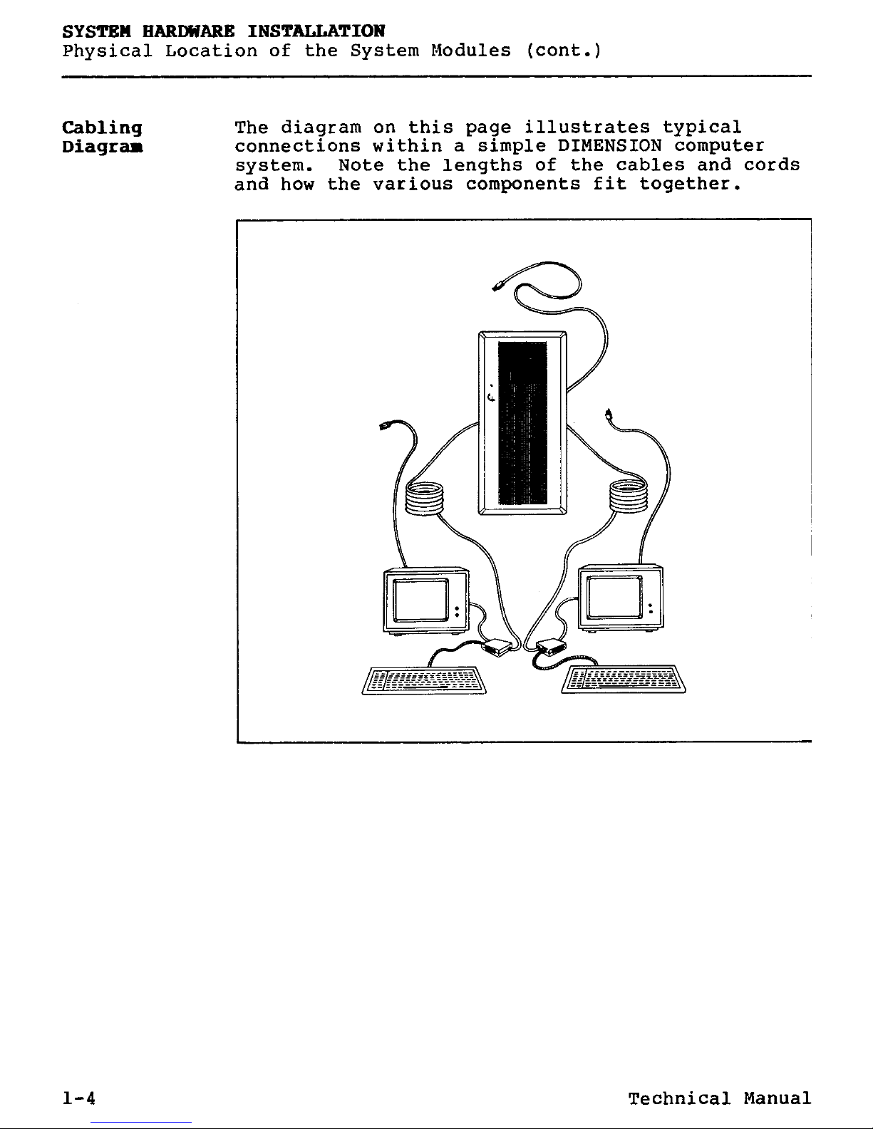
Cabling The diagram on this page illustrates typical
Diagram
connections within a simple DIMENSION computer
system. Note the lengths of the cables and cords
and how the various components fit together.
1-4 Technical Manual
SYSTEM HARDWARE INSTALLATION
(cont.) Physical Location of the System Modules
Cable
and
The following list of cord and cable lengths
Cord Lengths
details physical constraints you should consider
when locating the system components.
o
Central module power cord =
8 feet
o
Video display power cords =
6 feet
o
Keyboard cable (extended) =
6 feet
o
Workstation cable =
25 feet
o
Workstation extension cable =
100 feet
Technical Manual 1-5
SYSTEM HARIMARE
INSTALLATION
Central Module
Procedure
After you have positioned the system components,
Sugary
the next step in the hardware installation
procedure is to install and configure the central
module. The procedures on the following pages
describe how to:
o Place the central module on
its side and remove
the cover.
o Install the workstation circuit boards.
o Set the thumbwheel switches of the workstation
circuit boards.
o Connect the workstation cables to the
workstation circuit boards.
o Install the workstation
expansion
RAM circuit
boards. (Optional)
o Install the central
module expansion RAM
circuit boards. (Optional)
o Replace the cover.
o Check the selectable power line receptacle for
correct orientation of the voltage selection cam
and proper fuse.
o Install rubber feet to protect the base of the
central module.
o Return the central module to an upright
position.
o Install the power cord.
1-6 Technical Manual
SYSTEM HARDWARE INSTALLATION
(cont.) Central Module
Procedure
:
Central Module Installation and Configuration
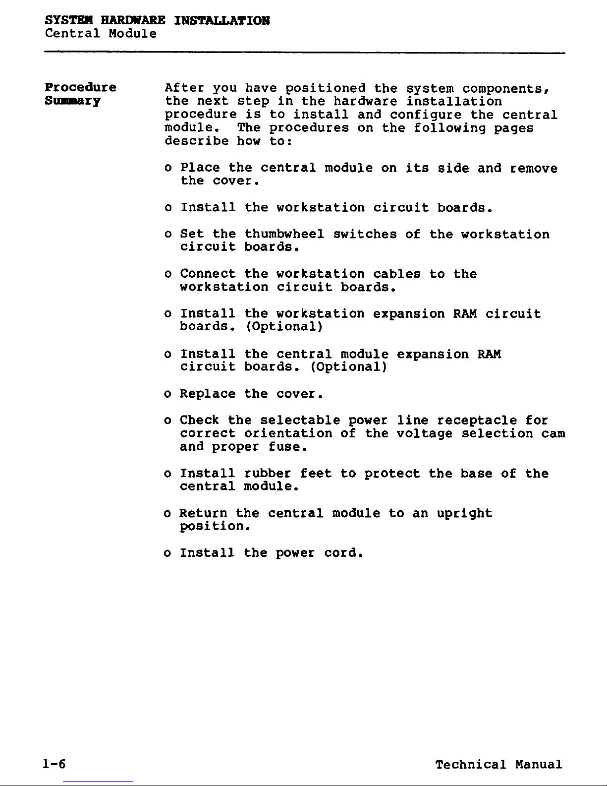
1. Place the central
module on its side,
unfasten the three
screws
which hold
the cover in place
and remove the
cover.
2. If you have to install
one or more expansion
RAM circuit
boards on
the central board, proceed to step #3. If you have
to install
one or more expansion
RAM circuit boards on work-
station circuit boards,
proceed
to step V. If you do not
have to install
expansion
RAM circuit
boards
, proceed to step
#10.
3. If you haven't already done so, unpack and examine the
expansion RAM circuit board and the two plastic standoffs
used with the central board. Compare these parts with the
pictures in steps #
4 and
#5. Notice how the two circuit
boards are connected.
An expansion RAM circuit board is fastened to the central
board in three places:
o by an
edge connector
which electrically mates the two
circuit
boards, and
o by the two plastic standoffs which physically fasten the
expansion
RAM circuit board to the central board.
Technical Manual 1-7
SYSTEM HARDWARE INSTALLATION
Central Module (cont.)
Procedure:
Central Module Installation and Configuration
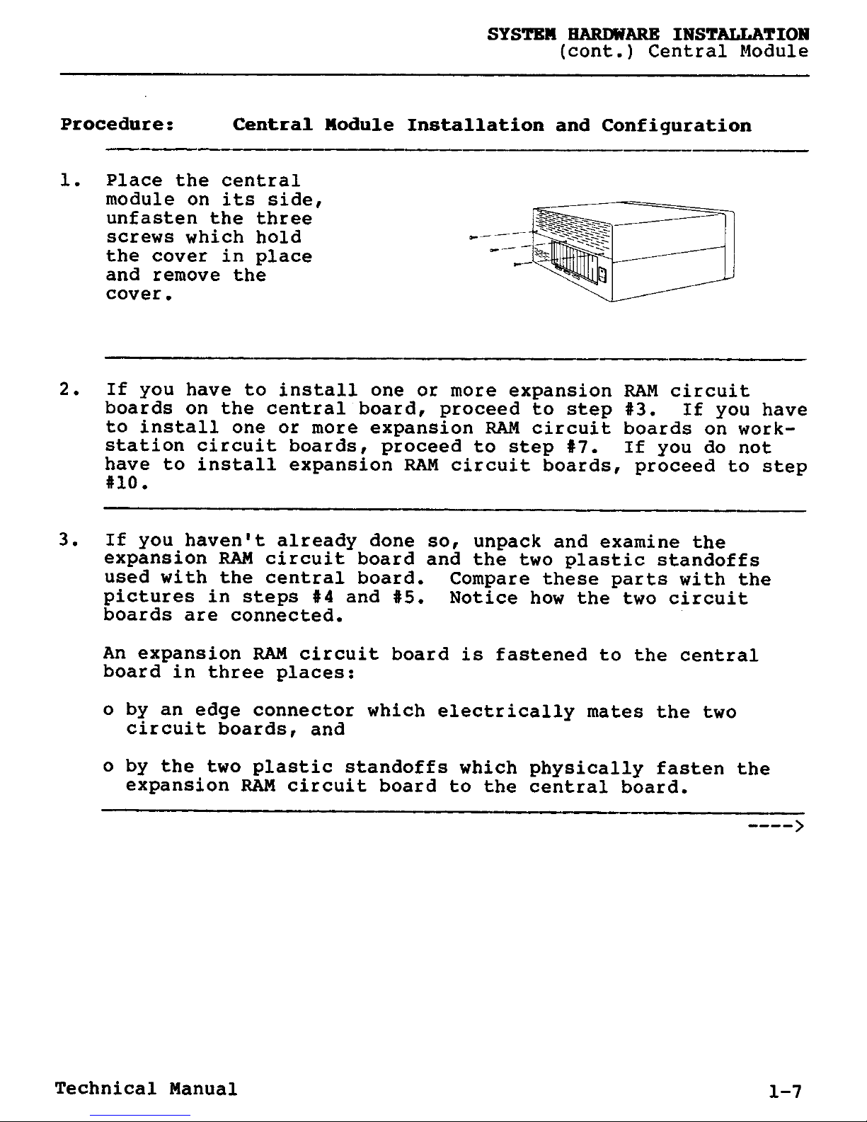
4. Mount the two
plastic standoffs by
pressing them in the
appropriate holes in
the central board.
5. Position the
expansion RAM
circuit board over
the two plastic
standoffs and the
central board
connector. Press
the expansion RAM
circuit board in
place.
6. If you have to install workstation expansion RAM circuit
boards, proceed to step
#
7; otherwise
,
proceed to step #10.
1-8 Technical Manual
SYSTEM HARD19ARE INSTALLATION
(cont.) Central Module
Procedure
:
Central Module Installation and Configuration
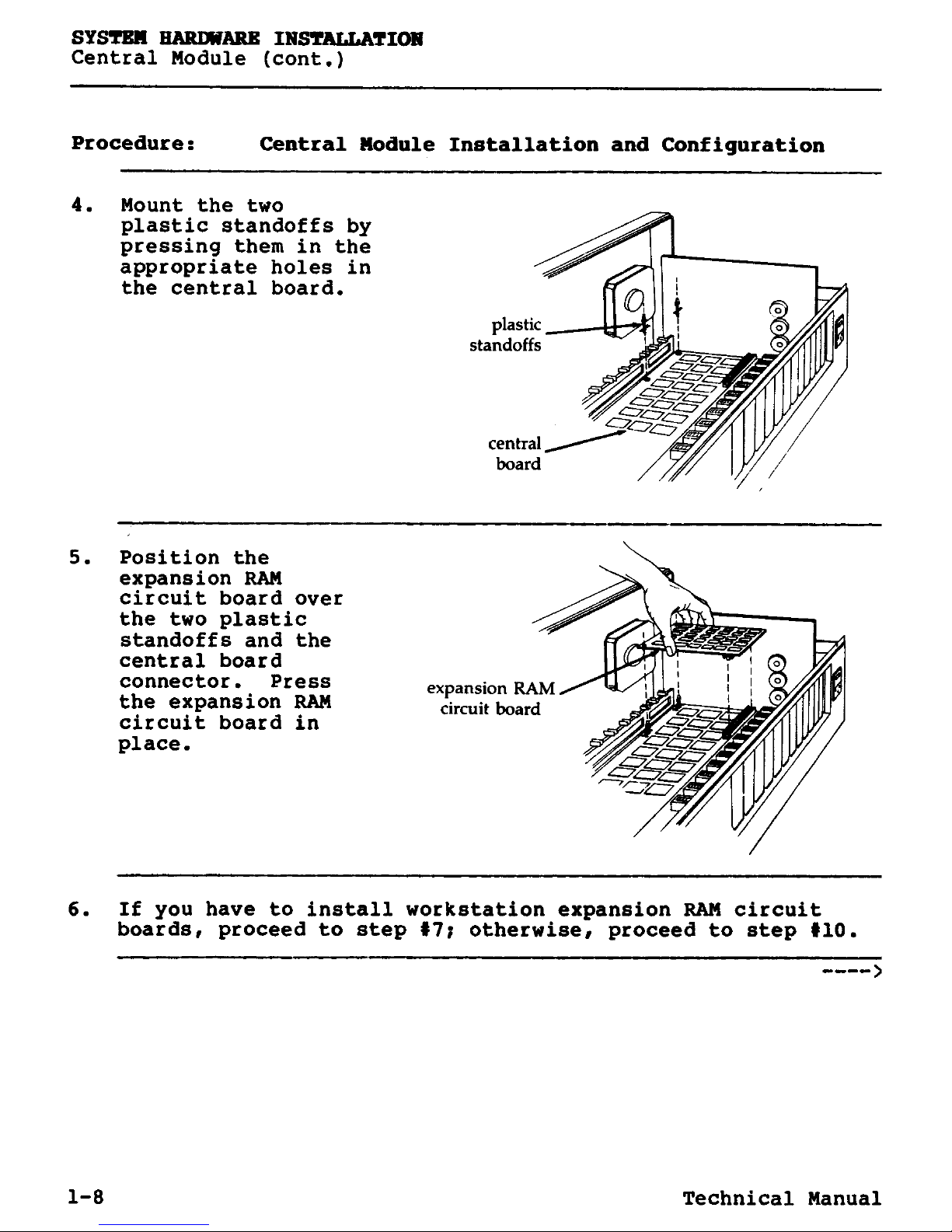
7. If you haven't
already done so,
unpack and examine
the workstation
expansion RAM circuit boards, the
two plastic standoffs used with each,
and all workstation
circuit boards.
An expansion RAM
circuit board is
fastened to the
workstation board
in three places:
o By an edge con-
nector which
electrically mates
the two circuit
boards, and
o By the two plastic
standoffs which
physically fasten
the expansion RAM
circuit board to
the workstation
board.
8. Mount the two
plastic standoffs by
pressing them in the
appropriate holes in
the workstation
board.
plastic
standoffs
Technical Manual 1-9
SYSTEM HARDWARE INSTALLATION
Central Module (cont.)
Procedure
:
Central Module Installation and Configuration
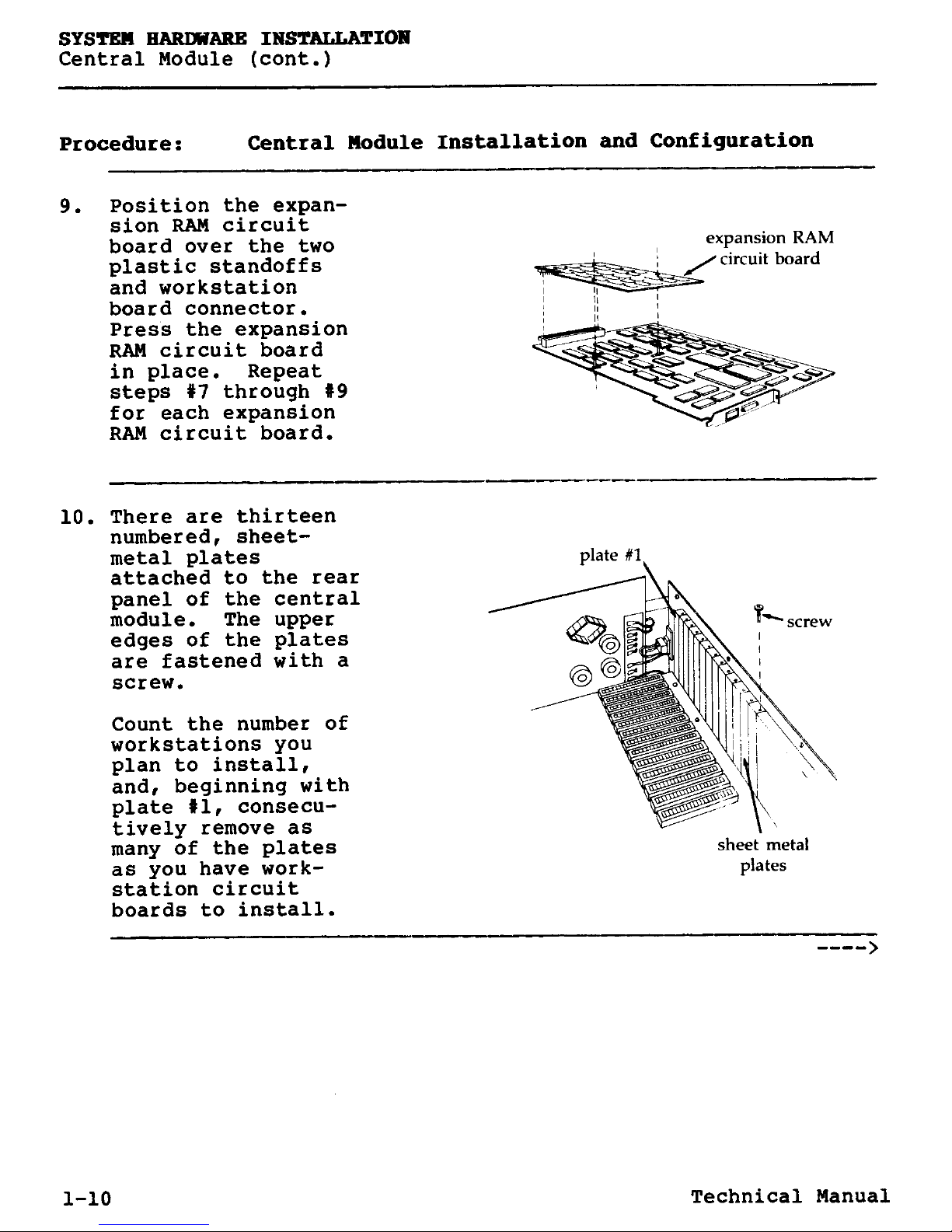
9. Position the expan-
sion RAM
circuit
board over the two
plastic standoffs
and workstation
board connector.
Press the
expansion
RAM circuit board
in place. Repeat
steps
#7 through #9
for each
expansion
RAM circuit board.
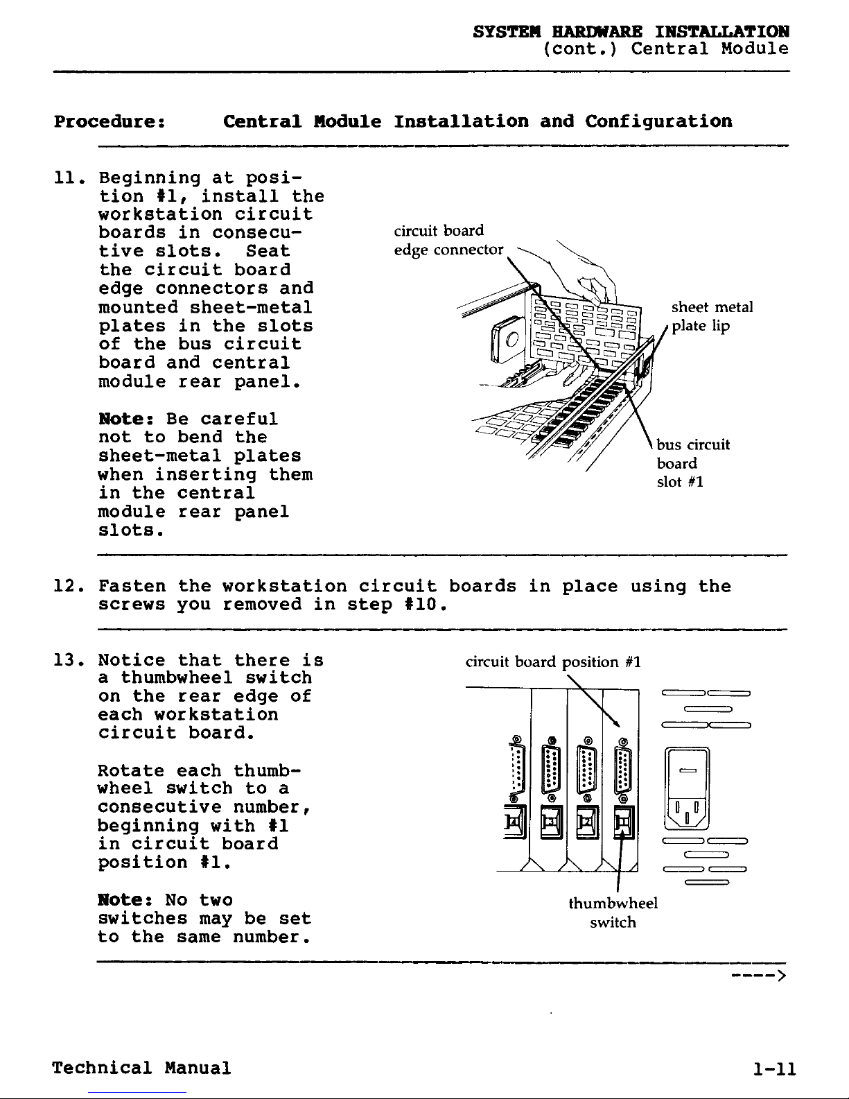
10. There are thirteen
numbered
,
sheet-
metal plates
attached to the rear
panel of the central
module. The upper
edges of the plates
are fastened with a
screw.
Count the number of
workstations you
plan to install,
and, beginning with
plate #1, consecutively remove as
many of the plates
as you have work-
station circuit
boards
to install.
1-10 Technical Manual
SYSTEM HARDWARE INSTALLATION
(cont.) Central Module
Procedure
:
Central Module Installation and Configuration
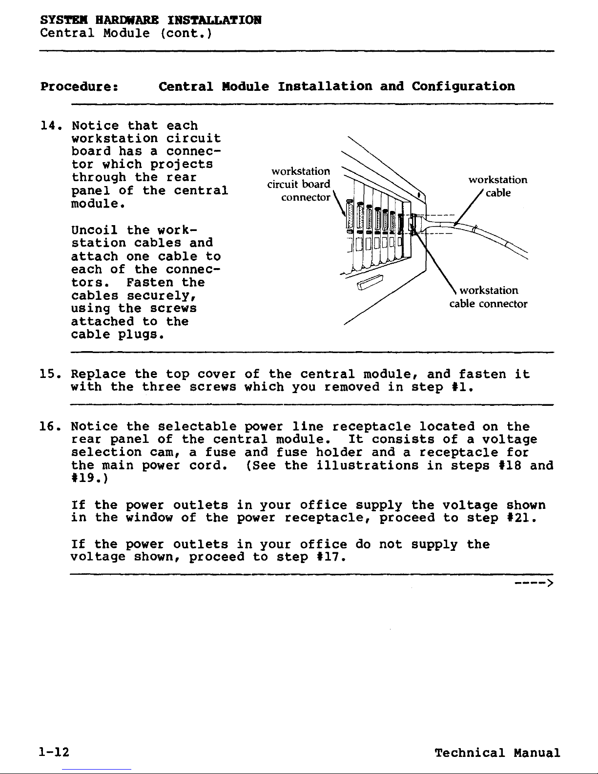
11. Beginning at position#1, install the
workstation circuit
boards in consecu-
tive slots. Seat
the circuit board
edge connectors and
mounted sheet-metal
plates in the slots
of the bus circuit
board and central
module rear panel.
Note
: Be careful
not to bend the
sheet-metal plates
when inserting them
in the central
module rear panel
slots.
12. Fasten the workstation circuit boards in place using the
screws
you removed in step #10.
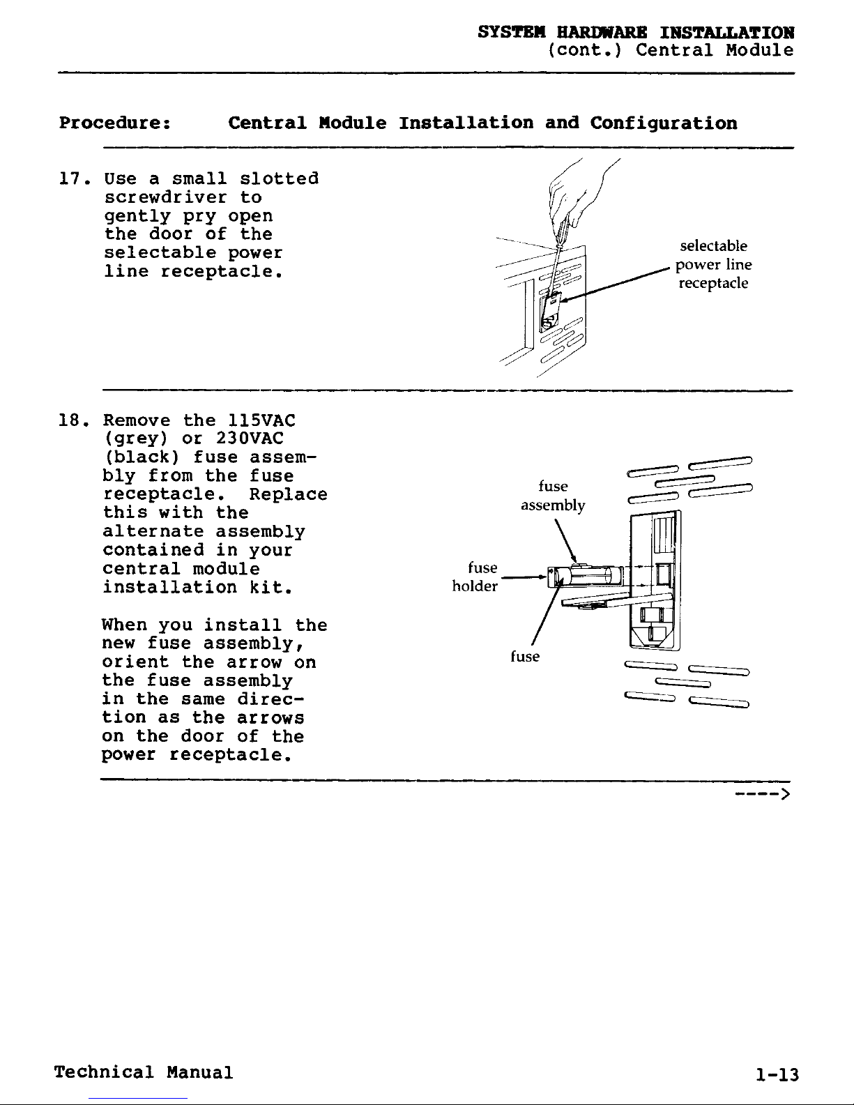
13. Notice that there is
a thumbwheel switch
on the rear edge of
each workstation
circuit board.
Rotate each thumbwheel switch to a
consecutive number,
beginning with #1
in circuit board
position #1.
Note: No two
switches may be set
to thesame number.
circuit board position #1
thumbwheel
switch
00
Technical Manual 1-11
SYSTEM HARDWARE INSTALLATION
Central Module (cont.)
Procedure
:
Central Module Installation and Configuration
14. Notice that each
workstation
circuit
board has a connec-
tor which
projects
through the rear
panel of the
central
module.
Uncoil the workstation cables and
attach one cable to
each of the connectors. Fasten the
cables securely,
using the screws
attached to the
cable plugs.
workstation
circuit board
connector
15. Replace the top cover of the central module
,
and fasten it
with the three screws which you removed in step #1.
16. Notice the selectable power line receptacle located on the
rear panel of the central module. It consists of a voltage
selection cam, a fuse and fuse holder and a receptacle for
the main power cord.
(
See the illustrations in steps #18 and
#19.)
If the power outlets in your office supply the voltage shown
in the window of the power receptacle
,
proceed to step #21.
If the power outlets in your office do not supply the
voltage shown, proceed to step #17.
1-12 Technical Manual
SYSTEM HARDWARE INSTALLATION
(cont.) Central Module
Procedure
:
Central Module Installation and Configuration
17. Use a small slotted
screwdriver to
gently pry open
the door of the
selectable power
line receptacle.
18. Remove the 115VAC
(grey) or 230VAC
(black)
fuse assem-
bly from the fuse
receptacle. Replace
this with the
alternate assembly
contained in your
central module fuse
installation
kit. holder
When you install the
new fuse assembly,
orient the arrow on
the fuse assembly
in the same direc-
tion
as the arrows
on the door of the
power receptacle.
selectable
power line
receptacle
C-
fuse
assembly
== O
fuse
Technical Manual 1-13

SYSTEM HARDWARE
INSTALLATION
Central Module (cont.)
Procedure
:
Central Module Installation and Configuration
19. Remove the voltage
selection cam from
the selectable power
line receptacle.
Rotate the cam
appropriately and
replace it so the
correct voltage sign
(either 115VAC or
230VAC)
appears
when the door of the
power receptacle is
closed.
20. Close the door of the selectable power line receptacle.
1-14 Technical Manual
SYSTEM HARDWARE INSTALLATION
(cont.) Central Module
Procedure
:
Central Module Installation and Configuration
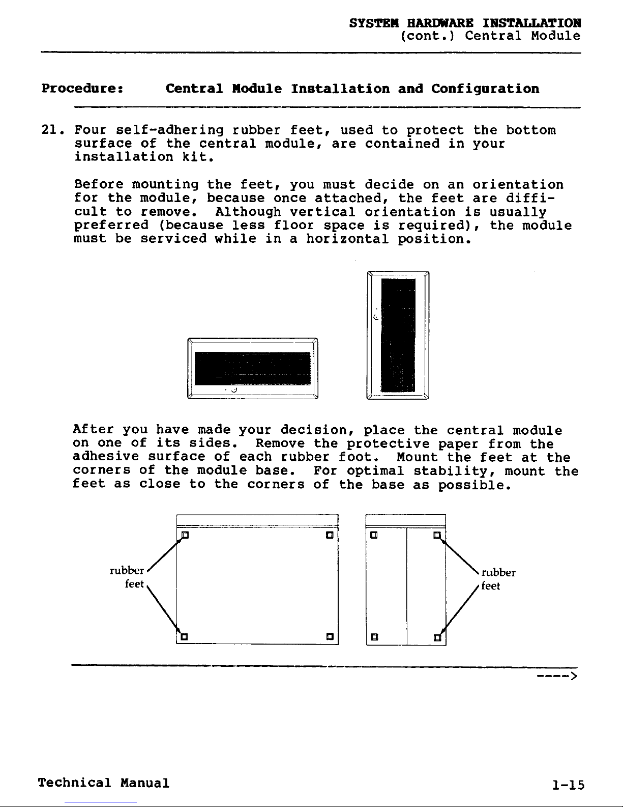
21. Four self-adhering rubber feet, used to protect the bottom
surface of the central module, are contained in your
installation kit.
Before mounting the feet, you must decide on an orientation
for the module, because once attached, the feet are diffi-
cult to remove. Although vertical orientation is usually
preferred (because less floor space is required), the module
must be serviced while in a horizontal position.
C
J
After you have made your decision, place the central module
on one of its sides. Remove the protective paper from the
adhesive surface of each rubber foot. Mount the feet at the
corners of the module base. For optimal stability, mount the
feet as close to the corners of the base as possible.
rubber
feet
Technical Manual 1-15
SYSTEM HARDWARE INSTALLATION
Central Module (cont.)
Procedure: Central Module Installation and Configuration
22. Return the central module to the chosen orientation. Do not
slide the module on its rubber feet until the adhesive has
cured for at least three hours
.
Maximum adhesion takes 24
hours.
23. Plug one end of the central module main power cord in the.
selectable power line receptacle, and plug the other end in
a wall outlet.
This completes the installation and configuration of the
DIMENSION central module.
1-16 Technical Manual
SYSTEM HARDWARE INSTALLATION
Workstation
Procedure
After you have installed and configured the
Summary
central module, the next step in the hardware
installation procedure is to install and configure
the workstations. The procedures on the following
pages describe how to:
o Plug the keyboard cable into the connector box.
o Plug the video cable into the video display.
o Mount the connector box.
o Mount the workstation label.
o Plug in the video display power cord.
o Adjust the tilt-and-swivel mechanism.
Technical Manual 1-17
SYSTEM HARDWARE INSTALLATION
Workstation (cont.)
Procedure: Workstation Installation and Configuration
1. Route the
uncoiled workstation cables to the workstations.
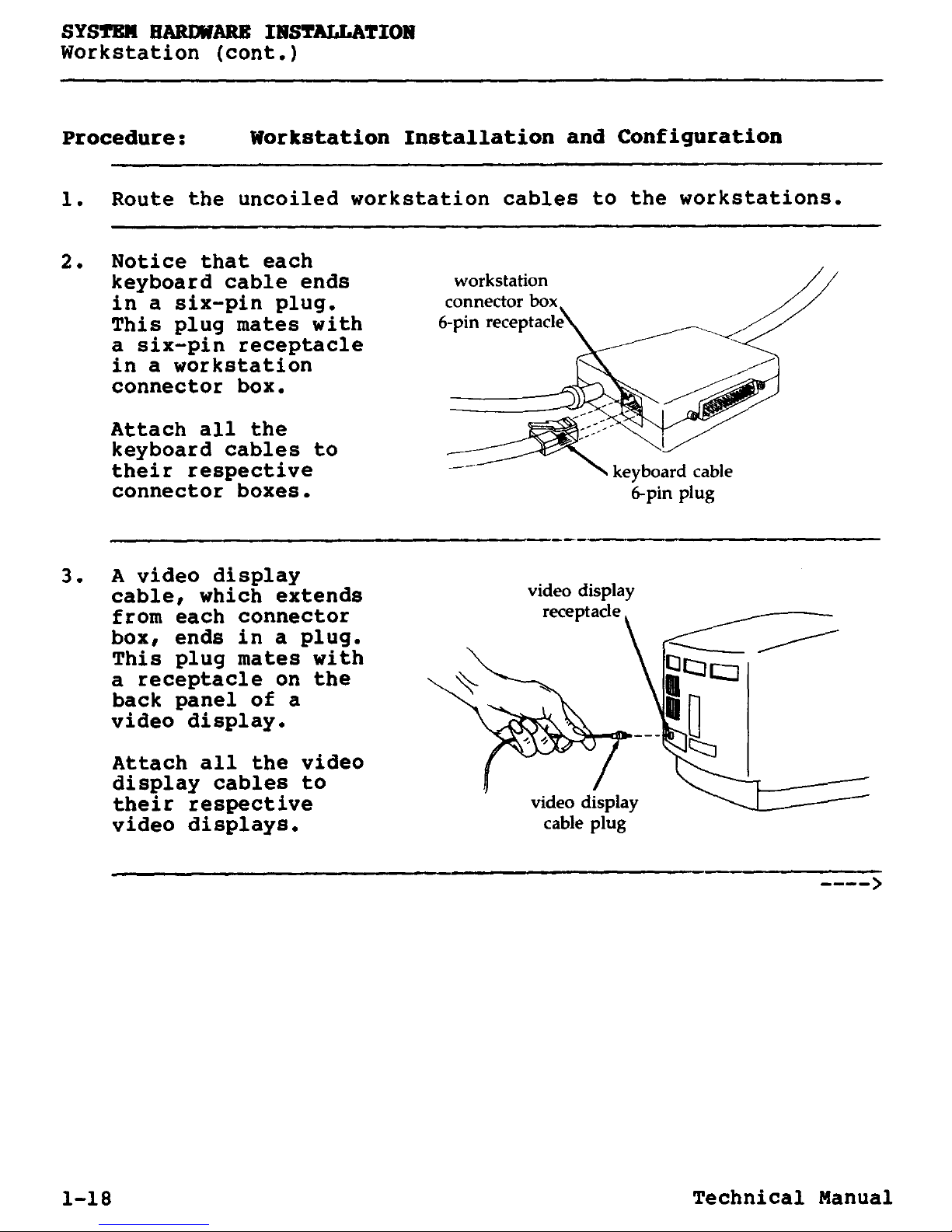
2. Notice that each
keyboard
cable
ends
workstation
in a six-pin
plug. connector box
This plug mates with
6-pin receptacle
a six-pin receptacle
in a workstation
connector box.
Attach all the
keyboard cables to
their respective
connector boxes.
3. A video display
cable,
which extends
from each connector
box, ends in a plug.
This plug
mates with
a receptacle on the
back panel of a
video display.
Attach all
the video
display cables to
their respective
video display
video displays
. cable plug
1-18 Technical Manual
 Loading...