

Page 1

Explorer 443d/443df
Fishfi nder
Installation and Operation Manual
www.northstarnav.com
Page 2

Page 3

DANGER
!
WARNING
!
CAUTION
IMPORTANT SAFETY INFORMATION
Please read carefully before installation and use.
This is the safety alert symbol. It is used to alert you to potential personal
injury hazards, Obey all safety messages that follow this symbol to avoidpossible injury or death.
WARNING indicates a potentially hazardous situation which, if not avoided,
could result in death or serious injury
CAUTION indicates a potentially hazardous situation which, if not avoided,
could result in minor or moderate injury.
CAUTION
DISCLAIMER: It is the owner’s sole
responsibility to install and use the instrument
and transducers in a manner that will not cause
accidents, personal injury or property damage.
The user of this product is solely responsible for
observing safe boating prac tices.
BRUNSWICK NEW TECHNOLOGIES INC. AND ITS
SUBSIDIARIES AND AFFILIATES DISCLAIM ALL
LIABILIT Y FOR ANY USE OF THIS PRODUCT IN A
WAY THAT MAY CAUSE ACCIDENTS, DAMAGE OR
THAT MAY VIOLATE THE LAW.
Governing Language: This statement,
any instruction manuals, user guides and
other information relating to the product
(Documentation) may be translated to, or
CAUTION used without the safety alert symbol indicates a potentially hazardous situation which, if not avoided, may result in property damage.
has been translated from, another language
(Translation). In the event of any conf lict
between any Translation of the Documentation,
the English language version of the
Documentation will be the official version of the
Documentation.
This manual represents the Explorer 443d/443df
as at the time of printing. Brunswick New
Technologies Inc. and its subsidiaries and
affiliates reserve the right to make changes to
specifications without notice.
Copyright © 2006 Brunswick New Technologies
Inc. Northstar™ is a registered trademark of
Brunswick New Technologies Inc
FCC Statement
Note: This equipment has been tested and found to comply with the limits for a Class B digital device,
pursuant to Part 15 of the FCC Rules. These limits are designed to provide reasonable protection
against harmful interference in a normal installation. This equipment generates, uses and can radiate
radio frequency energy and, if not installed and used in accordance with the instructions, may cause
harmful interference to radio communications. However, there is no guarantee that interference
will not occur in a particular installation. If this equipment does cause harmful interference to radio
or television reception, which can be determined by turning the equipment off and on, the user is
encouraged to try to correct the interference by one or more of the following measures:
Reorient or relocate the receiving antenna.
Increase the separation between the equipment and receiver.
Connect the equipment into an output on a circuit different from that to which the receiver is
connected.
Consult the dealer or an experienced technician for help.
A shielded cable must be used when connecting a peripheral to the serial ports.
Page 4

Contents
1 Introdu ction .......................................................................................................................................... 6
1-1 Benefits of the Explorer 443d/443df . . . . . . . . . . . . . . . . . . . . . . . . . . . . . . . . . . . . . . . . . . . . . . 6
1-2 How the Explorer 443d/443df works . . . . . . . . . . . . . . . . . . . . . . . . . . . . . . . . . . . . . . . . . . . . . .7
2 Basic Op eration ......................................................................................................................................7
3 Setti ng up the Explore r 443d/443df ....................................................................................................... 9
3-1 Setup > System . . . . . . . . . . . . . . . . . . . . . . . . . . . . . . . . . . . . . . . . . . . . . . . . . . . . . . . . . . . . . . . . . . 11
3-2 Setup > Sonar . . . . . . . . . . . . . . . . . . . . . . . . . . . . . . . . . . . . . . . . . . . . . . . . . . . . . . . . . . . . . . . . . . . 11
3-3 Setup > Fuel
3-4 Setup > Logs . . . . . . . . . . . . . . . . . . . . . . . . . . . . . . . . . . . . . . . . . . . . . . . . . . . . . . . . . . . . . . . . . . . . 13
3-5 Setup > Alarms . . . . . . . . . . . . . . . . . . . . . . . . . . . . . . . . . . . . . . . . . . . . . . . . . . . . . . . . . . . . . . . . . . 14
3-6 Setup > Units . . . . . . . . . . . . . . . . . . . . . . . . . . . . . . . . . . . . . . . . . . . . . . . . . . . . . . . . . . . . . . . . . . . . 14
3-7 Setup > Comms (443df only) . . . . . . . . . . . . . . . . . . . . . . . . . . . . . . . . . . . . . . . . . . . . . . . . . . . . . . .15
3-8 Setup > Calibrate . . . . . . . . . . . . . . . . . . . . . . . . . . . . . . . . . . . . . . . . . . . . . . . . . . . . . . . . . . . . . . . . 15
4 Using the E xplorer 443d/443d f ............................................................................................................. 17
4-1 Interpreting the display . . . . . . . . . . . . . . . . . . . . . . . . . . . . . . . . . . . . . . . . . . . . . . . . . . . . . . . . . . 17
4-2 Single and Dual frequency fishfinding . . . . . . . . . . . . . . . . . . . . . . . . . . . . . . . . . . . . . . . . . . .19
4-3 Fish detection and display . . . . . . . . . . . . . . . . . . . . . . . . . . . . . . . . . . . . . . . . . . . . . . . . . . . . . . . 21
4-4 Gain . . . . . . . . . . . . . . . . . . . . . . . . . . . . . . . . . . . . . . . . . . . . . . . . . . . . . . . . . . . . . . . . . . . . . . . . . . . . . 22
4-5 Range . . . . . . . . . . . . . . . . . . . . . . . . . . . . . . . . . . . . . . . . . . . . . . . . . . . . . . . . . . . . . . . . . . . . . . . . . . . 23
5 The Disp lays ......................................................................................................................................... 24
5-1 Sonar display . . . . . . . . . . . . . . . . . . . . . . . . . . . . . . . . . . . . . . . . . . . . . . . . . . . . . . . . . . . . . . . . . . .24
5-2 Sonar Zoom display . . . . . . . . . . . . . . . . . . . . . . . . . . . . . . . . . . . . . . . . . . . . . . . . . . . . . . . . . . . . .25
5-3 Sonar Bottom display . . . . . . . . . . . . . . . . . . . . . . . . . . . . . . . . . . . . . . . . . . . . . . . . . . . . . . . . . . . .26
5-4 Sonar 83/200 display . . . . . . . . . . . . . . . . . . . . . . . . . . . . . . . . . . . . . . . . . . . . . . . . . . . . . . . . . . . .26
5-5 Sonar A-Scope display . . . . . . . . . . . . . . . . . . . . . . . . . . . . . . . . . . . . . . . . . . . . . . . . . . . . . . . . . .26
5-6 A-Scope perspective view . . . . . . . . . . . . . . . . . . . . . . . . . . . . . . . . . . . . . . . . . . . . . . . . . . . . . . .27
5-7 Fuel display
5-8 Data display . . . . . . . . . . . . . . . . . . . . . . . . . . . . . . . . . . . . . . . . . . . . . . . . . . . . . . . . . . . . . . . . . . . . 28
5-9 About display . . . . . . . . . . . . . . . . . . . . . . . . . . . . . . . . . . . . . . . . . . . . . . . . . . . . . . . . . . . . . . . . . . . 28
(available on 443df only) . . . . . . . . . . . . . . . . . . . . . . . . . . . . . . . . . . . . . . . . . . . . . . . . 12
(443df only) . . . . . . . . . . . . . . . . . . . . . . . . . . . . . . . . . . . . . . . . . . . . . . . . . . . . . . . . . . . .27
Northstar Explorer 443d/443df Installation and Operation Manual4
Page 5

6 Instal lation and Mainten ance ..............................................................................................................29
Wiring Options . . . . . . . . . . . . . . . . . . . . . . . . . . . . . . . . . . . . . . . . . . . . . . . . . . . . . . . . . . . . . . . . . . . . . .29
6-1 What comes with this product? . . . . . . . . . . . . . . . . . . . . . . . . . . . . . . . . . . . . . . . . . . . . . . . . . . 31
6-2 Options and Accessories . . . . . . . . . . . . . . . . . . . . . . . . . . . . . . . . . . . . . . . . . . . . . . . . . . . . . . . . . 31
6-3 Mounting and removing the display unit . . . . . . . . . . . . . . . . . . . . . . . . . . . . . . . . . . . . . . . . 31
6-4 Systems of several instruments
(443df 0nly) . . . . . . . . . . . . . . . . . . . . . . . . . . . . . . . . . . . . . . .32
6-5 Cleaning and maintenance . . . . . . . . . . . . . . . . . . . . . . . . . . . . . . . . . . . . . . . . . . . . . . . . . . . . . .33
Append ix A - Specifica tions .................................................................................................................... 34
Append ix B - Dimensions ........................................................................................................................35
Append ix C - Tr oubleshootin g ................................................................................................................. 35
Important
It is your sole responsibility to install and use Northstar’s instrument & transducers in a manner that
will not cause accidents, personal injur y or property damage. Always observe safe boating practices.
The choice, location, angle and installation of the instrument & transducers are critical to
performance of the system as intended. Follow instructions in this manual carefully. If in doubt,
consult your Nor thstar dealer.
Ensure that any holes cut are in a safe position and will not weaken the boat’s structure. If in
doubt, consult a qualified boat builder.
Do not install plastic through hull transducers in solid wooden hulls. Leaking through the hull
may result.
Do not install bonze transducers in metal hulls. This will cause elec trolytic corrosion that may
result in damage to the hull or transducer.
Sonar Performance: The accuracy of the sonar depth display can be affected by many factors,
including the type and location of the transducer and water conditions. Ensure that the transducer
is located and used correc tly.
Fuel Computer: Do not rely on the fuel computer as the sole source of information regarding
available fuel onboard. Fuel economy can change drastically depending on boat loading and sea
conditions. Fuel Computer information should be supplemented by visual or other checks of the
fuel load. This is necessary due to possible operator errors such as forgetting to reset the fuel used
when filling the tank, running the engine with the Fuel Computer not switched on, or on other
operator ac tions that may render the device inaccurate. Always carry adequate fuel onboard for the
intended trip, plus a reserve to allow for unforeseen circumstances.
Failure to adhere to these warnings may lead to death, serious injury or property damage.
Northstar disclaims all liability for installation or use of this product that causes or
contributes to death, injury or property damage or that violates any law.
As Northstar is continuously improving this product we retain the right to make changes to the
product at any time which may not be reflected in this version of manual. Please contact your
nearest Nor thstar office if you require any further assistance.
Northstar Explorer 443d/443df Installation and Operation Manual 5
Page 6

1 Introduction
Congratulations on choosing a Northstar fishfinder.
For maximum benefit, please read this manual
carefully before installation and use.
This manual describes how to install and set
up the Explorer 443d/443df and the associated
dual-frequency transom transducer. (If a through
hull transducer is used, refer to the Installation
Instructions supplied with that transducer.)
This manual also explains how to operate the
Explorer 443d/443df effectively and provides
troubleshooting information and performance tips.
1-1 Benefit s of the Explorer 443d/443df
The Explorer 443d/443df is a high quality, dualfrequenc y sonar fishfinder that is supplied with
a dual-frequency transducer. It uses a 16 level
greyscale FSTN display for easy daylight viewing
that can be dimmed for night fishing. The bracket
mounting option also allows the fishfinder to be
tilted and swivelled for optimum viewing.
The dual frequency capabilit y enables the
Explorer 443d/443df to operate and display:
• At a high frequency of 200 kHz.
• At a low frequency of 83 kHz.
• Both frequencies side -by-side on a split
display.
• Both frequencies combined together into a
single display.
This capability, combined with a variable power
output of up to 250 watts, ensures that the
Explorer 443d/443df operates effectively in
shallow and deep water.
The Explorer 443d/443df can detec t the bottom
to a depth of 750 feet (230 metres) depending on
the clarit y of the water, the ultrasonic frequency
chosen and the t ype of transducer used.
The Northstar fishfinder can be used to find fish,
to locate features on the bottom such as reefs or
wrecks and to help recognize favourite fishing
spots from the bottom profile.
The Northstar fishfinder can also assist with
navigation by providing depth information to
help identify the depth contours marked on
Important
It is vital to the performance of the fishfinder
that the transducer is installed in the best
location. Please follow the installation
instructions very carefully.
charts. The Explorer 443d/443df is particularly
suited to work with the Explorer 538.
The two instruments can be connected together
using either NavBus or NMEA, so they can share
data. (only applies to Explorer 443df )
!
CAUTION
IMPORTANT NOTE ON USE. While any fishfinder
can be used as an aid to navigation, accuracy
can be influenced by many factors including
the location of the transducer. It is the user’s
responsibilit y to ensure that the Explorer
443d/443df is installed and used correctly.
With the optional fuel kit, the Explorer 443df also
becomes a sophisticated and easy-to-use
fuel computer.
All of the Northstar 400 Series fishfinders use
new proprietary SBN-II Technology for sonar
processing to improve Signal enhancement,
Bottom recognition and Noise rejection.
SBN-II Technology uses digital adaptive filter
algorithms to enhance all returned signals. At the
same time, SBN-II Technology uses active noise
control to reject interference, which can often be
mistaken by fishfinders for true returns.
Using SBN-II Technology, the Northstar fishfinder
analyses the reflec tions from each pulse, filters
false returns and displays what is in the water
under the boat. See section 4-1 Interpreting the
display, for more information.
Northstar Explorer 443d/443df Installation and Operation Manual6
Page 7

1-2 How the Explorer 443d/443df works
The Explorer 443d/443df has two par ts:
- the transducer attached to the hull
- the display unit.
The transducer generates an ultrasonic pulse
(sound that is above the hearing range of
the human ear), which travels down towards
the bottom at a speed of about 4800 ft/sec
(1463 m/sec), spreading out into a cone shape.
When the pulse meets an object, such as a fish or
the bottom, it is partly reflected back up towards
the boat as an echo. The depth of the objec t or
bottom is calculated by the E xplorer 4 43d/443df
by measuring the time taken bet ween sending a
pulse and receiving the echo. When an echo has
been returned, the next pulse is sent.
The Explorer 443d/443df converts each echo
into an electronic signal, displayed as a vertical
line of pixels. The most recent echo appears on
2 Basic Operation
Key Names
If a menu is not displayed then go to the sonar
ESC display. If a menu is displayed then cancel any
changes and return to the previous menu.
DISP Shows the Display menu.
, Cursor keys move the selec tion highlight and
, change settings.
MENU Press to show the Options menu on a display; press
again to show the Setup menu.
ENT Confirms any changes or from a sonar display shows
the Gain controls.
+ Increases the Range.
the extreme right of the display, with the older
echoes being scrolled towards the lef t, eventually
disappearing off the display.
The scroll sp eed depends upon the water depth
and scroll speed setting. See section 3-2 Setup >
Sonar and section 4-1 Interpreting the display, for
more information.
The appearance of echoes displayed are affec ted
by:
• the fishfinder settings (frequency selected,
range and gain settings)
• echoes (dif ferent fish types, dif ferent bottom
types, wrecks and seaweed)
• noise (water clarity and bubbles).
See section 4-1 Interpreting the display, for more
information.
— Decreases the Range.
AUTO Select fishing/cruising or manual operating mode
Powers On and Of f; shows the Backlight control.
Northstar Explorer 443d/443df Installation and Operation Manual 7
Page 8

Power On / Auto Power
Press to turn the fishfinder on.
If the fishfinder is wired for auto power, it turns
on automatically whenever the boat’s ignition
is turned on. This ensures that the engine hours
counter and optional fuel f unctions are activated.
A title display appear s briefly. This is followed
automatically by the Installation menu the fir st
time the fishfinder is switched on. Use this menu to
specify the l anguage (see section 3-1 Setup > System)
and units (see section 3- 6 Setup > Units).
At all other times, the title display is followed by
the display that was used most recently.
If the transducer is not connected, the
message: Enter simulate mode? will
appear. Press
No or Never. (If the transducer was not
intentionally disconnected, turn of f the fishfinder
and refer to the section on Troubleshooting in
Appendix B.)
to
switch between Yes,
or
Press ENT to confirm the selection and the
startup sequence will continue.
Key Operatio n
The fishfinder is operated through menus.
To select a me nu item:
1. Press DISP or MENU
2. Press
3. Press ENT to select the item.
To change a number, word or setting:
1. Use the cursor keys,
the number, word or setting and to make the
change(s).
2. Press ENT to confirm ; ESC to cancel.
or to move the highlight to
the item.
, , ,
to highlight
Power Off
To turn the fishfinder off, hold . A countdown
box appears. Continue to hold for 3 seconds
until the fishfinder turns of f.
Note: If the unit is wired for Auto Power (sec tion
6-5 Wiring options) the fishfinder can be turned
off only when the boat ’s ignition is turned off.
Backlight Adjustment
To change the backlight level:
1. Press
2. The display and keys are backlit, with a choice
Press
3. To change contrast:
4. Press ENT to save settings.
5. Press ESC to exit.
Press
backlight setting and default contrast.
briefly to show the display
controls.
of 16 brightness levels.
to dim or to brighten.
i Press
ii Press <, > to adjust
twice to return to the maximum
Northstar Explorer 443d/443df Installation and Operation Manual8
Menu Note:
Some menu items in the
Explorer 443d/443df menu’s
utilize checkboxes.
If the box is selected or
‘checked’ (contains a check
or tick), then that function is
enabled or ON.
If the box is de-selected
or ‘un-checked’ (does not
contain a check or tick), then
that function is disabled
or OFF.
To select or de-select
a checkbox, highlight the
menu item and press ENT.
Page 9

Simulate Mode
An internal simulator allows users to learn how to operate the fishfinder off the water.
In Simulate mode the word Simul ate f lashes on the bottom of the display. The fishfinder generates
data so that all the main displays appear to be operational.
Use Setup > Simulate as follows:
1. Press MENU twice to show the Setup menu.
2. Highlight Simulate.
3. Press ENT to select or de -select.
Manual, Fish ing and Cruising Mode s
Press AUTO to select one of the three following operating modes:
• Cruise mode. Use this when on the move. The Explorer 443d/443df prominently displays the water
depth and automatically adjusts Range and Gain so that the bottom trace is displayed. Depth is
displayed in large digits.
• Fishing mo de. Use this when fishing.
The Explorer 443d/443df prominently displays fish, the bottom profile, wrecks, rocks and all the
details that help to find fish. Gain and Range are optimized automatically, increasing the sensitivity
and fishfinding ability.
• Manual mode. Use this to fine-tune the fishfinding ability of the Explorer 443d/443df. Best
results are of ten achieved in manual mode, but practice and experience are required to obtain the
optimum settings for dif ferent conditions. Gain, gain threshold and pulse power can all be adjusted.
Manual mode stores the most recent settings, so these do not have to be reset each time manual
mode is selected.
3 Setting up the Explorer 443d/443df
Press MENU twice, to show the Setup menu, then select a particular option using the or cursor
keys. (Section 2 Basic Operation, describes the basic use of keys.)
The Setup menu and options are summarized below. The fac tory default s ettings are sh own where
applicable.
Each Setup menu option is explained in the following sections.
Northstar Explorer 443d/443df Installation and Operation Manual 9
Page 10

The Setup menu a nd options
System - see section 3-1
Sonar - see section 3-2
Fuel - see section 3-3
Logs - see section 3-4
Alarms - see section 3-5
Comms - see section 3-7
Simulate - see section 2
Northstar Explorer 443d/443df Installation and Operation Manual10
Units - see section 3-6
Calibrate - see section 3-8
Page 11

3-1 Setup > System
Press MENU once or more until the Setup menu
is displayed, then select System :
Language
Select the language for the displays. The options
are: English, Italian, French, German, Spanish,
Dutch, Swedish, Portuguese, Finnish Greek and
Croatian.
Tip: In case you can’t read the current langu age, the
language settin g is found at the top of the system
menu.
Backlight
Select this option to adjust backlighting and
contrast controls.
Key beep
Enables or disables the beep when a key
is pressed.
Auto power of f
Select to have the fishfinder power off
automatically every time the boat’s ignition is
switched of f. This applies only if the display unit
is wired for Auto Power. See section 6-5 Wiring
Options.
Snooze Mode
This power saving option slows the sounding rate
(time between each ultrasonic pulse) to a user
specified interval from 5 minutes to 2 hours. The
fishfinder appears to turn of f, however all alarms
operate normally. To return to normal operation,
press Power button. Ideal to be used as an
anchor alarm.
Factory re set
This option returns all of the fishfinder settings
(except the language) to the default fac tory
settings shown in section 3 Setting up the
Explorer 443d/443df.
A warning bo x asks: Are you sure? Selec t Ye s
and press ENT to conf irm.
Sonar (FISH 443df)
Select to enable sonar functions. Deselect if the
unit is to be used as a Smar tCraft only display.
SmartCraft (FISH 443df)
Select to enable SmartCraft functions. SmartCraf t
is only available with certain Mercur y engines,
and requires an optional SmartCraft Gateway.
3-2 Setup > Sonar
Press MENU once or more until the Setup menu
is displayed, then select Sonar:
Northstar Explorer 443d/443df Installation and Operation Manual 11
Beam
There is a choice of Narrow (200kHz),
Wide(83kHz), Mixed and Auto. For more info
about selecting a suitable frequency for water
conditions, see section 4-2 Single and Dual
Frequency Fishfinding.
Page 12

Scroll speed
Use this to set the scroll speed on the display.
There is a choice of: Ver y Fa st, Fast,
Medium, Slow and Pause. The depth of the
water also af fects the speed of the display.
Faster scroll speeds combined with a slow
boat speed (typically between 2 and 6 knots)
shows the most fish detail. Medium or Slow
scroll speeds result in sonar information being
displayed over a longer period, but with less
detail. See Section 4-1 Interpreting the display, for
more information.
Fish sy mbols
These appear only in the main sonar displays. Fish
symbols can be shown in three ways:
• As a fish symbol (Sym bol).
• As a fish symbol with the depth
(Sym bol+ dept h). The depth is shown
beside the fish symbol.
• As a depth (Dept h). The depth is shown
above where the fish was detec ted
• Switched off (Off) so that echoes are not
converted to fish symbols but are displayed
directly.
See section 4-3 Fish detec tion and display, for
more information about fish symbols.
3-3 Setup > Fuel (available on 443df only)
These features can be used only when the
optional single or twin engine fuel kit has been
installed.
Press MENU once or more until the Setup menu
is displayed, then select Fuel:
It is recommended that the fuel tank capacity is
measured by draining the fuel tank, then filling it
to capacit y. After filling, note the reading from the
fuel dispenser’s gauge.
Note: Beware of air pocke ts, especially in underf loor
tanks .
Fish sensitivity
Use this function to adjust the minimum fish
detection level. Select Low to reject noise and
small fish. Select High to detect maximum
number of fish.
Digit size
Use this to remove or change the size of the
depth display on the sonar displays. There is a
choice of: Small, Medium and Large.
Pale tte
Use this to selec t a color palette. Each color
within the palette represents a different echo
strength, as shown on the sonar displays.
There is a choice of three color palettes: Black,
White and High Contrast.
Interference filter
This filters the echo signal to reduce high-level,
spiky inter ference, such as engine noise and
makes small fish harder to see.
Select to add filter.
Pulse power
This can be used to specif y the power output
of the transmitted ultrasonic pulse. Low power
output conserves the boat’s batter y, but only
works in shallow water.
There is a choice of Auto, Low, Medium or
High. The Auto setting is recommended.
!
WARNING
Northstar fuel kits are only suitable for petrol/
gasoline engines. Fuel consumption can change
drastically depending upon the boat loading
and the sea conditions. Always carr y adequate
fuel for the journey, plus a reser ve.
Tan k full
Select Tank full each time the fuel tank(s)
are completely refilled. When asked Are you
sure? select Ye s. Otherwise, the reading
on the Fuel display (see section 5-6 Fuel
Display) and the Low Fuel Alarm (see section
3 -5 Setup > Alarms) are meaningless.
Northstar Explorer 443d/443df Installation and Operation Manual12
Page 13
Set remaining
Before doing a partial refill of the tank or
removing fuel manually from the tank (for
example, by siphoning it of f):
1. Note the Remaining reading on the
Fuel display.
2. Note how much fuel is added or removed.
3. Calculate how much fuel is now in the tank.
4. Select Set remaining and update
the reading.
It is essential to do this whenever some fuel is
added or removed. Otherwise, the reading on
the Fuel display (see section 5-6 Fuel Display)
and the Low Fuel Alarm (see sec tion 3-5 Setup >
Alarms) are meaningless.
Clear used
Select Clear used to set Used (the
amount of fuel used) to zero. Do this to start
measuring the amount of fuel used over a certain
time or distance.
When asked Are you sure? select Yes.
Tan k size
Enter the capacity of the fuel tank.
Flow f ilter
Most engines do not draw fuel from the tank at a
steady rate. To give a stable fuel flow reading, the
fishfinder calculates the f low value(s) by taking
several measurements and averaging them. Use
the Flow filter to set the period over which the
fuel flow is averaged.
The Flow filter can be set from 0 to 30 seconds.
Use the lowest value which gives a stable f low.
Usually a value of 5 to 10 seconds will give a
satisfac tory result for two-stroke carburettor
engines. Fuel injected or four-stroke engines may
require a larger value.
This setting affects the Fuel flow and Fuel
economy reading on the Fuel display (see
section 5-6 Fuel display) but it does not affect the
Fuel used reading.
Speed Source
Select speed input from water speed transducer
or external GPS source (an external GPS source
must be connected to the Fishfinder via NavBus
– see section 3-7 Setup > Comms.)
Num engines
Set the number of engines to 0, 1 or 2. If 0 is
selected the fuel features are turned off.
Calib rate
See section 3-8 Setup > Calibrate, for information
about calibrating the fuel transducer(s).
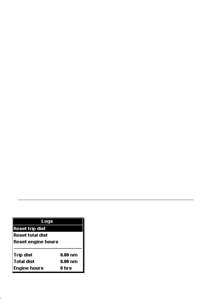
3-4 Setup > Logs
Press MENU one or more times until the Setup
menu is displayed, then selec t Logs:
Northstar Explorer 443d/443df Installation and Operation Manual 13
The values can be changed independently of
each other. These log values are saved when the
unit is turned off.
Reset trip di st
This resets the trip distance to zero.
Reset total d ist
This option resets the total distance to zero.
Reset engine hours
Use this option to reset the engine hours
to zero. This can be useful after an engine ser vice
or to count the engine hours between service
intervals.
Page 14
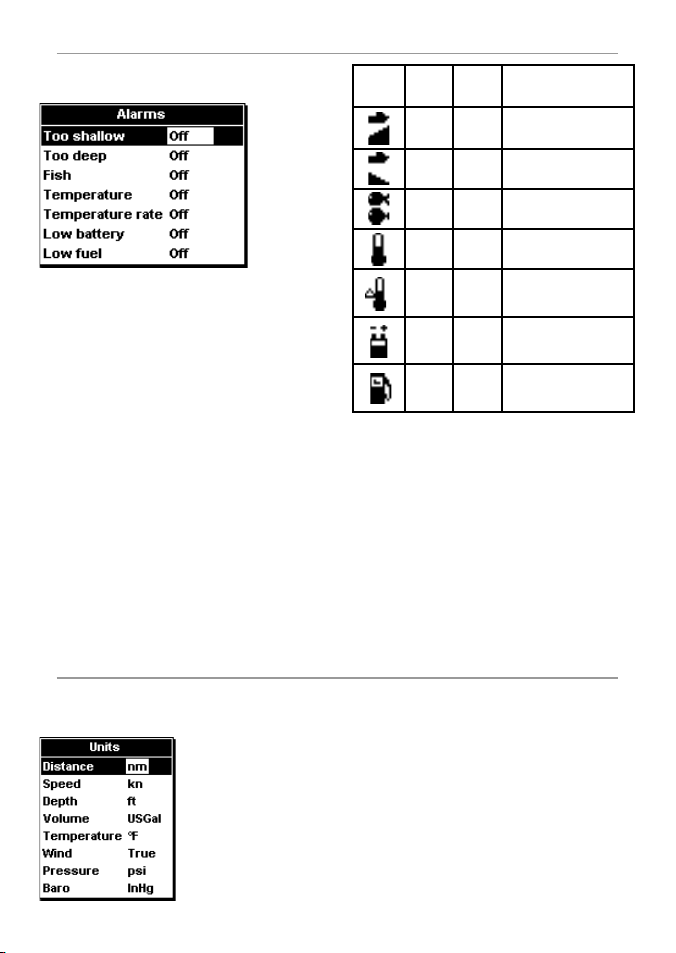
3-5 Setup > Alarms
Press MENU one or more times until the Setup
menu is displayed, then selec t Alarms:
Trigger settings can be defined to suit the boat
and individual preferences as follows:
Alarms can be set (enabled) to automatically
detect cer tain conditions, such as the water
being too shallow. Alarms that are enabled are
shown as black icons in the Alarm status box on
the sonar displays.
When an enabled alarm is triggered, the beeper
sounds, an alarm message is displayed and the
alarm status icon flashes.
Press ENT or ESC to acknowledge the alarm, stop
the beeper and close the alarm window. This
does not disable the alarm.
Alarms automatically re-enable
The Too shallo w, Too De ep and Low
battery alarms automatically re-enable when
the value moves outside the alarm trigger setting.
The Temperature alarm automatically
re-enables when the temperature is more
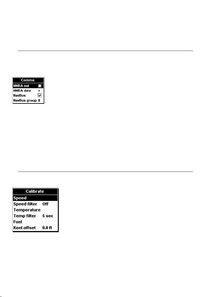
3-6 Setup > Units
Press MENU one or more times until the Setup
menu is displayed, then selec t Units:
The default units are
shown in this example.
Distance
Select from:
• nm (nautical miles)
• mi (miles)
• km (kilometres)
Northstar Explorer 443d/443df Installation and Operation Manual14
Symbol Alarm
Beeper
Name
Cycle
1
Too
/5 sec Depth is less t han
shallow
1
/2 sec Depth is greater t han
Too
deep
Fish 1 short
beep
1
/2 sec Temp erature equals
Temp.
1
Temp.
/2 sec Rate of change of
rate
1
Low
/2 sec Batter y voltage is
battery
1
Low
/2 sec Fuel remainin g equals the
fuel *
Alarm condition is met
when the:
the alarm tr igger value
the alarm tr igger value
Echo matches th e
profile of a f ish
the alarm tri gger value
temperature e quals the
alarm trigg er value
less than the al arm
trigger va lue
alarm trigg er value
*Only 4432
than 0.45°F (0.25°C) above or below the alarm
trigger setting.
The Temperature rate alarm automatically
re-enables when the rate of temperature change
falls below the trigger setting by more than 0.2°F
(0.1°C) per minute.
Flashing ligh t and/or externa l beeper
If a secondary alarm indicator is required,
a flashing light and/or external beeper can
be installed. These can be positioned anywhere
suitable on the boat. See section 6-5 Wiring
options.
Baro
• InHg (Inches of mercury)
• Mb (Millibars) - sometimes called kPa
Speed
Select from:
• kn (knots)
• mph (miles per hour)
• kph (kilometres per hour)
Wind
• True
• Apparent
Depth
Select from:
• ft (feet)
• m (metres)
• fa (fathoms)
Pressure
• kPa
• psi
Page 15
Fuel Temperature
Select from: Select either:
• Litres • °F (Fahrenheit)
• USGal (US gallons) • °C (Celsius)
• ImpGal (Imperial Gallons)
3-7 Setup > Comms (443df only)
Use this feature when the Explorer 443d/443df
is connected to other Northstar instruments
through NavBus or any compatible NMEA
instrument.
Press MENU once or more until the Setup menu
is displayed, then select Comm s:
NMEA Out
NMEA is generally used with third part y
instruments. Select to transmit NMEA
sentences (see Appendix A - Specifications).
3-8 Setup > Calibra te
Press MENU once or more until the Setup menu
is displayed, then select Calibrate:
The fuel options
can be calibrated
only when the
optional single
or twin engine
kit is installed on
petrol/gasoline
engines.
Speed*
Calibration may be required because different
hull shapes have dif ferent flow characteristics.
Obtain an accurate measurement of the boat’s
speed from a GPS receiver; or by following
another boat travelling at a known speed; or by
making a timed run over a known distance.
Northstar Explorer 443d/443df Installation and Operation Manual 15
NMEA data
Use this to specify which NMEA sentences will be
transmitted (see Appendix A - Specifications and
section 5-7 Data display, for information about
how to display NMEA data).
NavBus
NavBus is the preferred method for connecting
the Explorer 443df to other Northstar
instruments. Select if the instruments are
connected using NavBus.
NavBus Group
Use this when a group of Northstar instruments
are connected together using NavBus, to specify
a group of instruments for backlighting, if
required. Then, if the backlight set ting on one
instrument in the group is adjusted, the other
instruments change automatically. Otherwise,
select 0.
Note: for accurate calibration:
• The speed from a GPS receiver should be
greater than 5 knots.
• The speed from another paddlewheel
transducer should be between 5 and 20
knots.
• Best results are achieved in calm conditions
where there is minimal current (best at high
or low tide).
Use the cursor keys to display the speed readout
box, then increase or decrease the readout to
match the independent speed value.
Speed Filter*
Increase this setting to stabilise an erratic
speed reading. Decrease to improve reading
responsiveness. The speed filter can be set from
0 to 30 seconds.
* only availa ble on 443df
Page 16
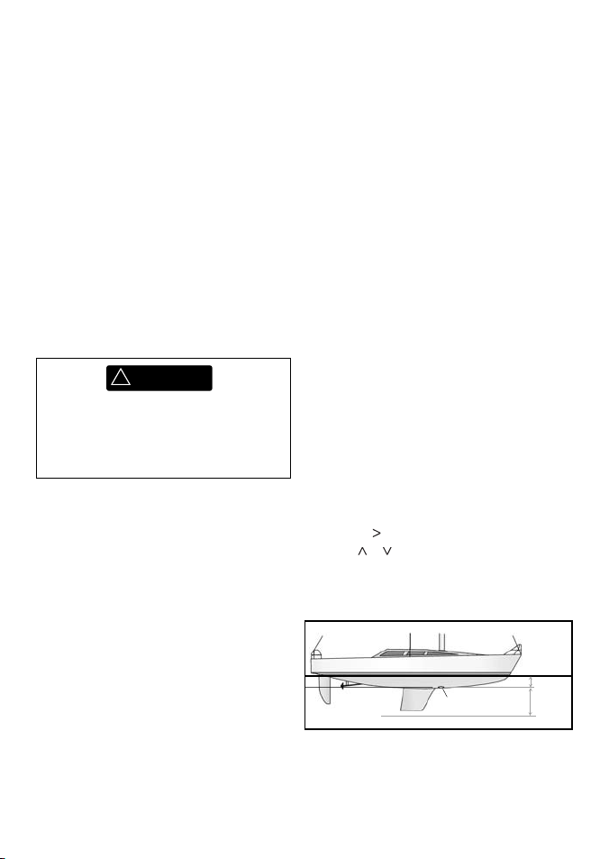
Tem per at ure
The factory set tings should be sufficiently
accurate for normal usage. To calibrate the
temperature readout, first measure the water
temperature with a thermometer known to
be accurate.
Use the cursor keys to display the temperature
readout box, then increase or decrease the
value to match the measured temperature. The
temperature can be set from 32° to 99.9°F (0° to
37.7°C) with a resolution of 0.1° unit.
To change the units between °F (Fahrenheit) or °C
(Celsius), see section 3- 6 Setup > Units.
Tem p filt er
Increase this setting to stabilise an erratic
temperature reading. Decrease to improve
reading responsiveness. The temperature filter
can be set from 0 to 30 seconds.
Fuel
!
WARNING
Extreme precautions must be observed
when carrying out this procedure.
Failure to do so could create hazardous
conditions that can cause serious personal
or property damage.
Calibrating the fuel usage can improve the
accuracy of fuel measurements.
Twin engine installations require each fuel
transducer to be calibrated. This can be done
at the same time with two portable tanks or at
different times using one portable tank.
Calibrating the fuel transducer(s) requires
accurate measurement of the fuel consumption.
This is best done using a small por table tank. At
least 4 gallons (15 litres) of fuel should be used to
ensure an accurate calibration.
It is often ver y difficult to fill underfloor tank s to
the same level t wice due to air pockets, so the
more fuel used, the more accurate the calibration.
To calibrate the fuel transducer(s), perform the
following steps:
1. Record the level of the fuel in the tank(s).
2. Connect the portable tank(s) to the engine
through the fuel transducer(s).
3. Run the engine at normal cruising speed
until at least 4 gallons (15 litres) of fuel has
been used per engine.
4. Check the actual amount of fuel used per
engine by refilling the portable tank(s) to
the original level and noting the reading(s)
from the fuel dispenser’s gauge.
5. Select Fuel. Use the cursor keys to change
the reading for each engine to match that
on the fuel dispenser’s gauge.
6. Press ENT when the reading is correct.
Note: If the fuel calibration options appear to
give erroneous readings af ter a while, first check
that the fuel sensor has been installed correctly
according to the installation instructions supplied
with it. Then see Appendix B - Troubleshooting.
Keel of fset
Keel offset is a depth correction representing the
vertical distance bet ween the depth transducer
and the location from which the depth is to be
measured.
Enter a positive keel offset value when the
transducer is located below the water sur face but
the total depth is required.
Enter a negative keel offset value when the
depth below the deepest part of the boat is
required (such as the keel, the rudder or the
propeller) and the transducer is located closer to
the water surface.
Use the cursor keys to selec t Keel offset,
then press
Use the
to display the Keel offset box.
or cursor keys to adjust the value.
Water surface
Positive
Depth of transducer
Transducer
Note: Boat illustrated uses a through hull transducer
value
Negative
value
Northstar Explorer 443d/443df Installation and Operation Manual16
Page 17
4 Using the Explorer 443d/443df
This section explains how to interpret the sonar
displays, when and why to use the dif ferent
frequencies and how fish are detected
and displayed.
4-1 Interpreting the d isplay
The sonar displays do not show a fixed distance
travelled by the boat; rather, they display a
history, showing what has passed below the boat
during a certain period of time.
The histor y of the sonar signal displayed depends
on the depth of the water and the scroll speed
setting.
In shallow water, the echoes have a short distance
to travel between the bot tom and the boat. In
deep water, the history moves across the display
more slowly because the echoes take longer to
travel between the bot tom and the boat. For
example, when the scroll speed is set to Fast,
at depths over 600ft it takes about 2.5 minutes
for each vertical line of pixels to move across the
display, whereas at 20f t it takes only about 4-5
seconds.
The scroll speed can be set by the user to display
either a longer history with less fish information
or a shorter history with more fish details. See
section 3-2 Setup > Sonar.
If the boat is anchored, the echoes all come from
the same area of bottom. This produces a flat
bottom trace on the display.
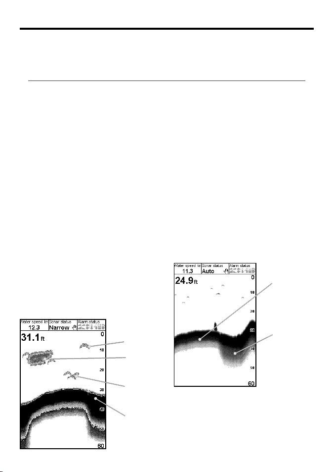
The screen shot shows a typical sonar display
with the Fish symbols turned Off.
It also describes Gain and Range and shows
examples of some of the different sonar displays.
Also see section 1-2 How the Explorer 443d/443df
works.
Strength of echoes
The colors indicate dif ferences in the strength of
the echo. The strength varies with several factors,
such as the:
• Size of the fish, school of fish or other object.
• Depth of the fish or object.
• Location of the fish or objec t. (The area
covered by the ultrasonic pulse is a rough
cone shape and the echoes are strongest in
the middle.)
• Clarity of water. Particles or air in the water
reduce the strength of the echo.
• Composition or densit y of the object or
bottom.
Note: Planing hulls at speed p roduce air bubbles and
turbulent water that bomba rd the tra nsducer. T he
resulting ultrasonic noise may b e picked up by the
transducer and obscure the real echoes.
Soft bottoms
such as mud,
weed and
sand show as
narrow bands
Single fish
Large
school of
fish
Small school
of fish
Bottom
Northstar Explorer 443d/443df Installation and Operation Manual 17
Bottom typ es
Mud, weed and sandy bottoms tend to weaken
and scatter the sonar pulse, resulting in a weak
echo. Hard, rocky or coral bottoms ref lect the
pulse, resulting in a strong echo. See sec tion 5-3
Sonar Bottom display.
Hard bottoms
such as rock
or coral show
as wide bands
Page 18
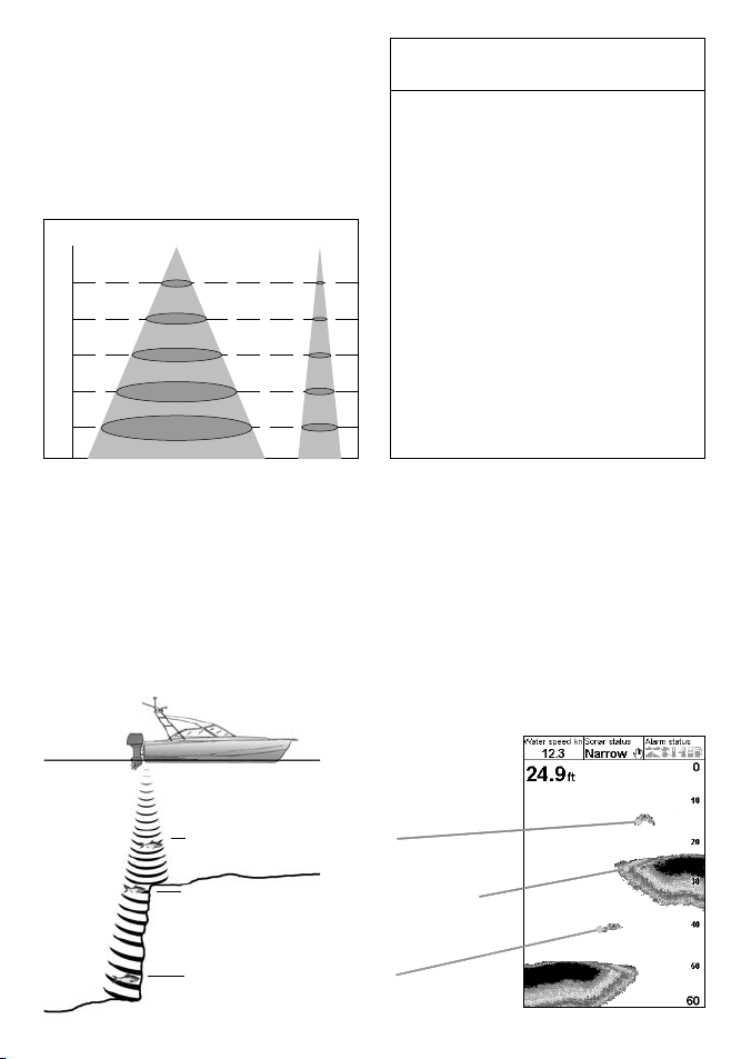
Frequency a nd cone width
The pulse generated by the Explorer 443d/443df
transducer travels down through the water,
spreading outwards to form a rough cone shape.
However, the cone width is dependent upon the
frequency of the pulse; at 83 kHz it is 20°, whereas
at 200 kHz it is 14°. The chart shows how the cone
width varies over depth for each frequency used.
Figures are approximate.
Depth 83 kHz 200 kHz
100
150
200
250
0
50
20°
18
30
55
73
91
14°
12
25
37
50
62
Water Cone width Cone width
Depth at 83 kHz at 200 kHz
10 4 2
20 7 5
30 11 7
40 15 10
50 18 12
60 22 15
70 25 17
80 29 20
90 33 22
100 36 25
150 55 37
200 73 50
300 109 75
400 146 100
500 182 125
600 218 149
700 255 174
800 291 199
900 328 224
1000 364 249
The differences in the cone width affect what is displayed. See section 4-2 Single and Dual Frequency fishfinding.
Shadows
Shadows are created around areas where the ultrasonic beam cannot ‘see’. These areas include hollows
on the bottom or beside rocks and ledges, where the strong echoes returned off the rocks obscure the
weak echoes of the fish and may also create a double bottom trace. See following for an example of the
sonar display in such an environment. A double bottom trace is shown on the display.
When looking for fish with the wide angled 83 kHz frequency, be aware of increased shadows. Use the
high frequency 200 kHz in areas that have rocks and ledges because this frequency reduces the shadow
effect considerably.
Exampl e of shadows
Sonar displ ay of same area
Fish is visible on the display
Fish is hidden by the strong echoes off the
bottom and is not shown on the display
Fish is visible on the display
Northstar Explorer 443d/443df Installation and Operation Manual18
Page 19
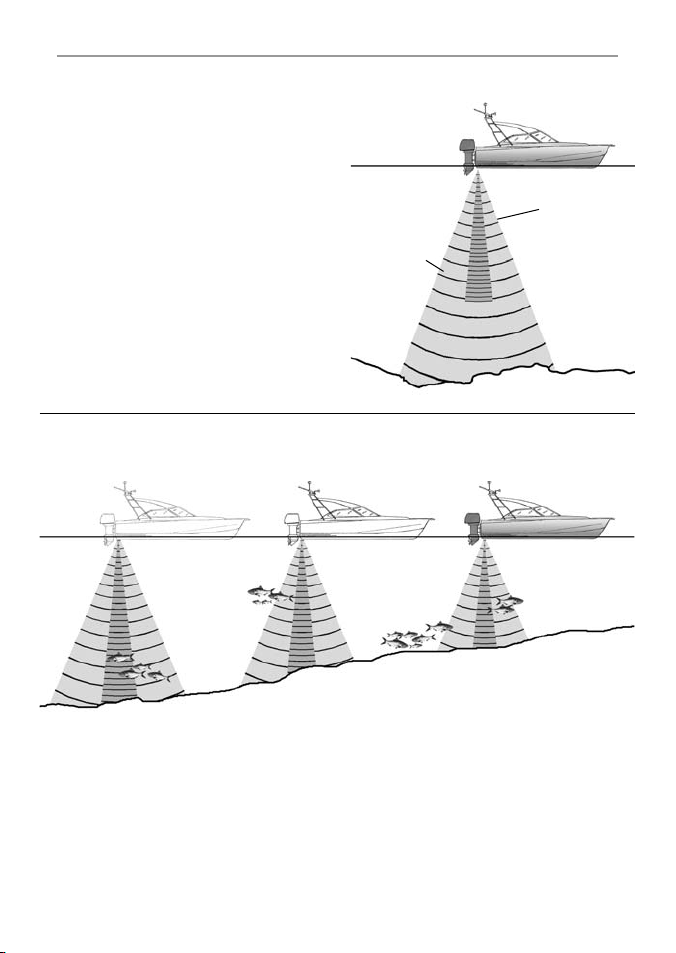
4-2 Single and Du al frequency fi shfinding
When to use 200 kHz
The 200 kHz frequency is best for seeing deep
bottoms, showing detail and reducing noise.
When to use 83 kHz
The 83 kHz frequency is ha s a w ider beam –g ood f or
locating features that can be examined in detail
at 200kHz.
Auto frequency
This shows 200kHz detail on screen, but uses
83kHz beam for locating fish further from boat.
Wide angle,
less detailed
83 kHz cone
Comparison of th e same fish scenario displ ayed at different f requencies:
Narrow angle,
more detailed
200 kHz cone
1 minute ago
Now
30 seconds ago
Northstar Explorer 443d/443df Installation and Operation Manual 19
Page 20
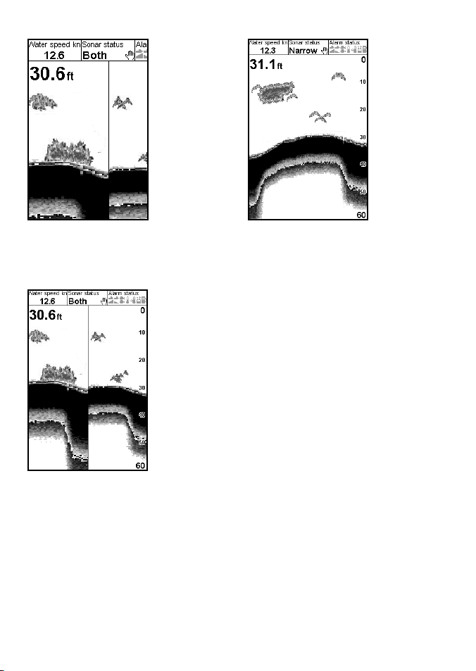
83 kHz display
200 kHz display
200/83 Khz displ ay
Note the wider
bottom trace
Dual screen
Note the
smaller, defined
fish arches and
more bottom
detail.
Northstar Explorer 443d/443df Installation and Operation Manual20
Page 21
4-3 Fish detectio n and display
Where to find f ish
Underwater features like reefs, wrecks and
rocky outcrops attract fish. Use the 83/200 kHz
frequenc y display to find these features, then look
for fish by passing over the feature slowly several
times using the Zoom display (see section 5-2
Sonar Zoom display). If there is a current, the fish
will often be found downstream of the feature.
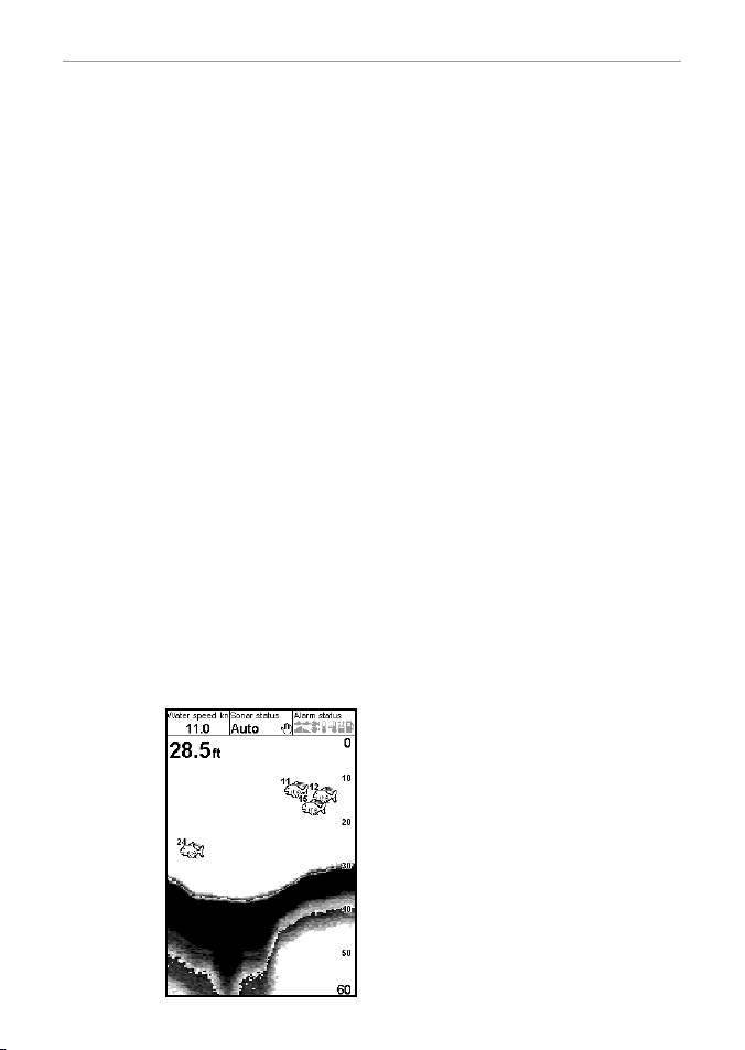
When fishing with the Explorer 443d/443df with
the Fish symbols Off, a weak fuzz y band may
appear bet ween the bottom trace and surfa ce. This
might indicate a thermocline - a rapid change in
water temperature, such as the ed ge of a warm or
cold current. The temper ature difference can form
a barrier which the fish may not s wim through. In
fresh water, fish of ten collect around a th ermocline.
Fish sy mbols
The fish symbol can be customized or switched off
altogether so that the echoes are not converted to
fish symbols on the display. See section 3-2 Setup >
Sonar. The differences between Fish symbol On and
Off are:
Fish symbols On
Using Nor thsta r’s SBN- II sonar technology the
fishfinder analyses all echoes and eliminates most false
signals and clutter so that remaining targets are most
likely fish. Depending on the strength of the remaining
echoes, they are displayed as either small, medium
or large fish symbols - with or without depth. While
the SBN -II processing is very sophisticated it is not
foolproof - there w ill be times when th e fishfinder
will not be abl e to differentiate betwe en large air
bubbles, rubbish containin g air, fishing floats etc.
and genuine fish.
The pict ure shows
the Sonar display
with the Fish
symbol: symbol
+ depth:
Fish symbols Off
For experienced users this always provides the
best information as every echo is displayed,
whether it is sur face clutter, a thermocline or a
fish.
The picture in section 4-1 Interpreting the display,
shows the Sonar display with the Fish symbols
Off. The fish appear as arches.
Fish a rches
In good conditions and with Fish symbols Off, a
fish passing through the cone -shaped ultrasonic
pulse is displayed as a fish arch. The 83 kHz
frequenc y uses a wider cone than the 200 kHz
frequenc y. This makes the fish arches easier to
see.
A fish arch occurs when a fish enters the weak
edge of the sonar cone, generating a weak echo
that is displayed as the first pixel of the fish arch.
As the fish moves closer to the middle of the
cone, the distance between the transducer and
the fish reduces and the echo is displayed at
progressively shallower depths, producing the
start of an arch. When the fish passes directly
beneath the middle of the cone, the echo
becomes strongest and thickest. A s the fish
passes out of the middle of the cone the reverse
happens with a progressively weaker and deeper
echo.
There are many reasons why fish arches may not
be seen. For example:
• Poor transducer installation (see Tran som
Transducers Installation Guide).
• If the boat is anchored then fish will tend to
show on the display as horizontal lines as they
swim into and out of the transducer sonar
beam. Slow speeds in deeper water give the
best fish arch returns.
• Range is impor tant. It will be much easier to
see fish arches when using zoom mode to
concentrate on a particular section of water,
rather than just displaying everything from
the surface to the bottom. Zooming increases
screen resolution and is necessary for good
fish arches.
Northstar Explorer 443d/443df Installation and Operation Manual 21
Page 22
• It is difficult to get fish arches in shallow water as the transducer sonar beam is very narrow near the
surface and fish do not stay within the beam long enough to display an arch. Several fish in shallow
water tend to display as randomly stacked blocks of pixels.
• Wave motion may result in distorted fish arches
4-4 Gain
Gain (sensitivity) controls the amount of
detail displayed on the Explorer 443d/443df.
Understanding how to set suitable Gain set tings
is important for optimum performance.
The Northstar fishfinder has three gain modes,
Cruising, Fishing and Manual.
• Cruising Mode
Use this mode to show only the bottom and
large fish.
• Fishing Mode
Use this mode to show as much detail as
possible.
• Manual Mode
The gain can be adjusted by the user to
compensate for water depth and clarity.
High Gain set tings may amplify the normal
background noise until it appears as random
pixels.
Note: The Gain mode automati cally changes to
Manual Gain if the gain o r threshold settings are
adjusted by the user.
Obtaini ng the best results
To obtain the best detection capability for both
fish and bottom we recommend the use of the
Sonar A-Scope display:
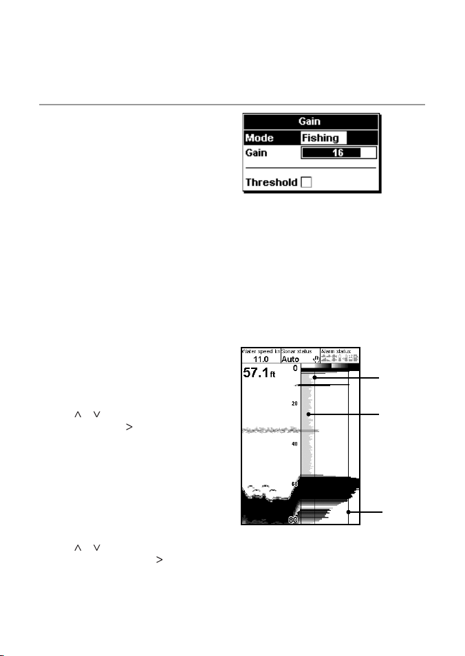
1. Set the threshold to 0%.
2. Adjust the gain until the threshold line is just
to the right of the unwanted noise.
Changing be tween Cruising, Fishi ng
and Manual
To change between Cruising, Fishing
and Manual
1. From any Sonar display, press ENT.
2. Use the
or cursor keys to highlight mode
option, then use the cursor key then select
desired option from list.
Gain
Threshold line
Unwanted
signal
Adjusti ng Gain and Thresho ld settings
The gain set tings and the threshold set tings can
be adjusted independently for each frequency
(83kHz and 200 kHz).
Use threshold to eliminate colors in the sonar
display.
1. From any Sonar display, press ENT.
2. Use the
or cursor keys to highlight the
desired setting, then use the cursor key
to change it.
Gain line
Northstar Explorer 443d/443df Installation and Operation Manual22
Page 23
4-5 Range
Range is the ver tical depth displayed on the
Explorer 443d/443df.
The Northstar fishfinder has two range modes,
Auto Range and Manual Range:
• In Auto Range, the fishfinder adjusts the
depth range automatically so the bottom is
always shown in the lower part of the display.
The use of Auto Range is recommended for
normal conditions.
• In Manual Range, the fishfinder shows only
a selected depth range. In areas of rapidly
changing bot tom depth, such as the sea floor
around pinnacles, it can be useful to prevent
the display from rescaling to always show
the bottom. If the bottom is deeper than the
specified depth range, it will not be shown
on the display.
Changing th e Range Mode
Press the + or - key to change to Manual Range
mode and to increase or decrease the range to
the desired depth. Values can be set between 10
ft. (3 m) to 1000 ft. (300 m).
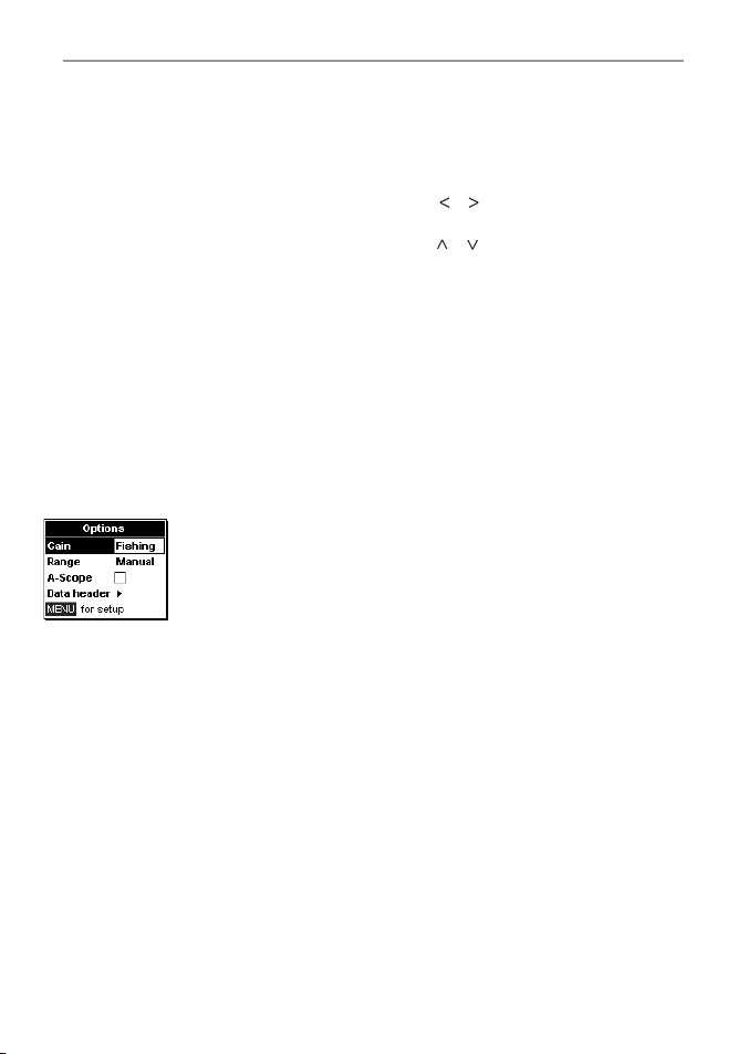
To change from the current mode:
1. From any Sonar display, press MENU to
display the Options menu.
2. Highlight Range, then use the cursor keys to
select Auto or Manual.
3. Press ENT to confirm.
Tip: To quickly enlarge from manual to auto -range
hold down + or - key for 1.5 seconds.
Zoom Range and Zoo m Offset
On the Sonar Zoom and Sonar Bottom displays,
a vertical bar is shown on the far right of the
display. This is the zoom bar. The zoom bar shows
the zoom range; that is, the area that
is magnified.
Use the
or cursor keys to adjust the
zoom range.
Use the
or cursor keys to adjust the
zoom offset.
Northstar Explorer 443d/443df Installation and Operation Manual 23
Page 24
5 The Displays
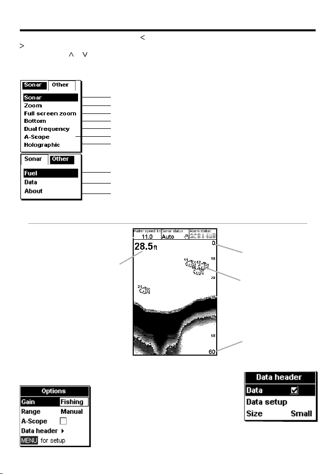
Press DISP to show the Display menu. Use or
to select display tab, then select a particular
display using the or cursor keys.
The Display me nu
5-1 Sonar display
Data header, set up to show the
boat speed, sonar status etc.
Depth (medium size digits)
To show the Sonar display, press
DISP and select Sonar Tab,
select Sonar and press ENT.
This display scrolls from right
(most recent echoes) to lef t
(oldest echoes) at the selected
frequenc y (see section 3-2 Setup
> Sonar).
To change items, press MENU until the
Options menu is shown.
Note: Refer to Section 3-2 Setup > So nar, fo r information about
customizing features on the sonar displ ays.
Sonar display at a single or mixed frequency (section 5-1)
Sonar split display with zoomed section (section 5-2)
Show zoomed section of sonar
Sonar flat bottom trace in zoomed section (section 5-3)
Sonar split display with 83 and 200 frequencies (sec tion 5-4)
Sonar split display with echo strength (section 5-5)
Show perspective view of sonar (section 5-6)
Fuel dat a (section 5-7)
Water temperature and depth history and boat data (sec tion 5-8)
Product and wiring information (sec tion 5-9)
Gain is explained in
section 4-4 Gain.
Range is explained in
section 4-5 Range.
A-scop e is
explained in section
5-5 Sonar A-Scope
display.
Northstar Explorer 443d/443df Installation and Operation Manual24
The Display menu is summarized here and each
display is shown in the following sections.
Most displays have an Options menu so that
relevant features can be changed quickly.
Surface
Fish symbols with depth
Bottom
Range
Data header
The data header can
be selec ted on or of f.
When selected, it is a
customizable feature
that can be used to
display up to 9 data
items, such as alarms
or water temperature.
Page 25
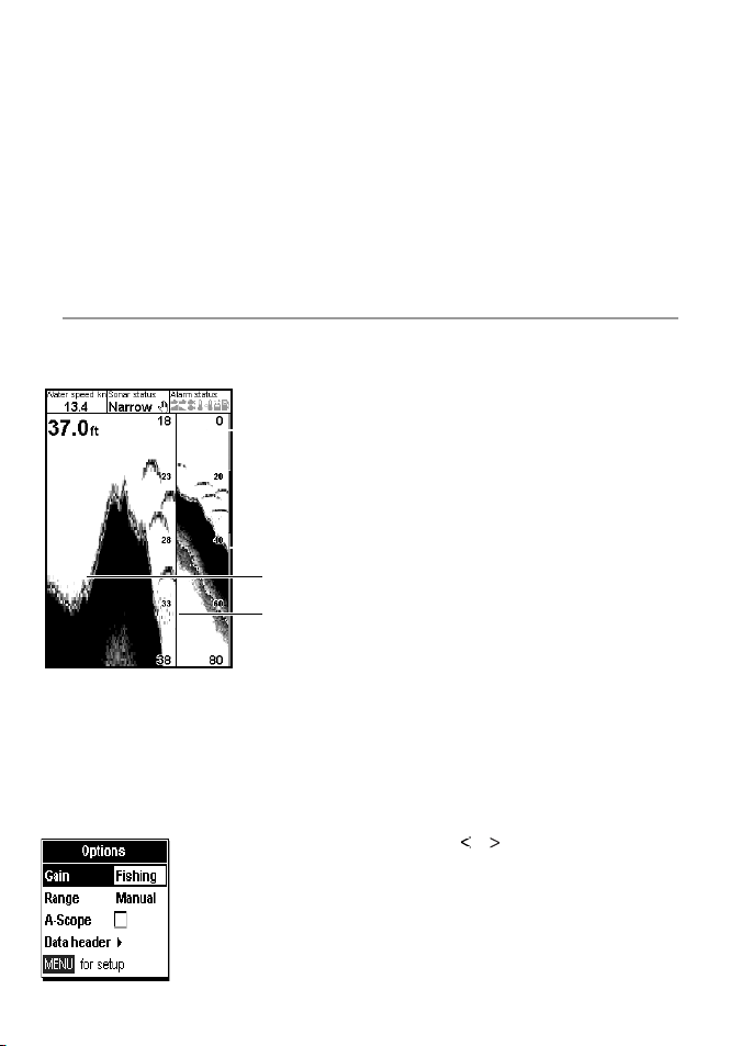
To customize the size of the Data header, highlight
Size and press ENT. There is a
choice of Small and Large.
To customize the data items to be displayed:
1. Highlight Data setup and press ENT.
The Data header increases in size to display all
data fields. Some data fields may be blank.
2. Use the cursor keys to move from data field to
data field.
3. Press ENT at any data field to show the list of
data items that can be displayed there.
4. Highlight the required data item and press
5-2 Sonar Zoom displa y
To show the Sonar Zoom display, press DISP and
select Sonar Tab, select Sonar Zoo m and
press ENT.
Sonar histor y
Zoom bar
Zoom section
Divider line
The split display shows the sonar history on the
right side and the zoom section on the lef t.
The zoom bar on the far right shows the area that
is magnified in the zoom section. See section 4-5
Range, for information about adjusting the Zoom
Range and Zoom Offset.
To change items, press MENU until the
Options menu is shown.
Northstar Explorer 443d/443df Installation and Operation Manual 25
ENT. The data item is immediately displayed in
that data field.
5. Press ESC when finished and the Data header
resizes automatically.
Sonar History
To review an old sonar echo, use < and > to move
back and for ward through the sonar history. The
time since the echoes shown on the screen were
recorded is displayed at the bot tom of the screen.
Press ESC to return to the most recent echo.
Gain
Gain is explained in section 4-4 Gain.
Range
Range is explained in section 4-5 Range.
A-Scope
A-Sco p e is explained in sec tion 5-5 Sonar
A-Scope display.
Bottom lock
If Bottom lock is selected, the zoom section
moves so the bot tom is always displayed in the
zoom section, regardless of changes in depth.
If Bottom lock is not selected, the bottom
will not be displayed in the zoom section when it
is outside the range covered by the zoom bar.
Using the Bottom Lock and the A-Scope features
together can be a powerful aid in recognising the
type of bottom.
Split Ratio
Use this to change the split ratio between the
zoom and the sonar history sections displayed.
The default split ratio is 50%.
1. Highlight Split Ratio and press ENT.
A left arrow and right arrow appear on either
side of the divider line.
or
2. Use the
position of the divider line, then press ENT.
The adjustable range of the split ratio is from
20% to 80% . For 100% zoom, use ‘full-screen
zoom’ display.
cursor keys to adjust the
Data header
Data header is explained in section 5-1 Sonar
display.
Page 26
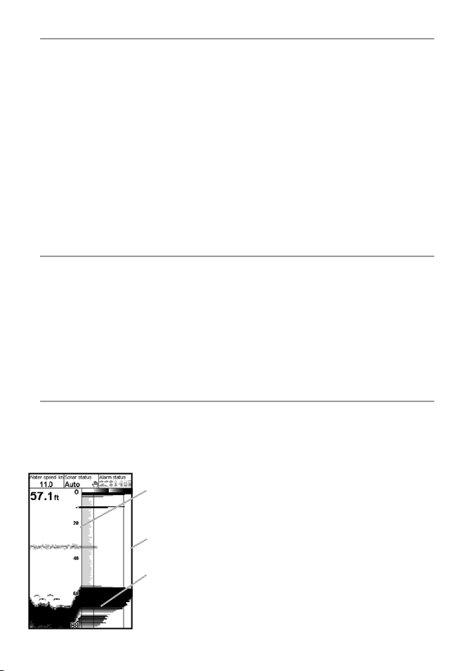
5-3 Sonar Bottom d isplay
To show the Sonar Bottom display, press DISP
and selec t Sonar Tab, selec t Sonar Bottom
and press ENT.
This shows a split display, with the sonar history
on the right side and the zoom section on the
left. The bottom signal is shown as a flat trace in
the centre of the zoom section.
Showing the bottom as a flat trace can make it
easy to compare the echo strengths shown in the
bottom signals. This can help to identify the type
of bottom and objects close to the bottom.
The zoom bar can only indicate the zoom range.
It cannot indicate the zoom of fset as this changes
for each sounding displayed on the display.
The zoom bar is fixed in the middle of the display.
5-4 Sonar 83/200 di splay
To show the Sonar 83/200 display, press DISP
and selec t Sonar Tab, selec t Sonar 83/200
and press ENT.
This shows a split display, with the 83 kHz sonar
history on the left side and the 200 kHz sonar
history on the right side. Gain settings can be set
independently for each frequency. Range settings
apply to both sections of the display.
5-5 Sonar A-Scope display
To show the Sonar A-Scope display, press DISP
and selec t Sonar Tab, selec t Sonar A-Scope
and press ENT.
Use this to analyse the sonar data in detail and
optimize the Gain settings.
Divider line
between sonar
history and
A-scope
Gain setting
(strongest echo for
display)
Gain threshold
(weakest echo for
display)
See section 4-5 Range, for information about
adjusting the Zoom Range and Zoom Of fset.
To change items, press MENU until the
Options menu is shown.
Gain is explained in section 4-4 Gain.
Range is explained in sec tion 4-5 Range.
A-scop e is explained in section 5-5 Sonar
A-Scope display.
Data header is explained in section 5-1 Sonar
display.
Bottom lock and Split ratio are
explained in section 5-2 Sonar Zoom display.
To change items, press MENU until the
Options menu is shown. Gain is explained in
section 4-4 Gain.
Range is explained in sec tion 4-5 Range.
A-scop e is explained in section 5-5 Sonar
A-Scope display.
Data header is explained in section 5-1 Sonar
display.
Split ratio is explained in section 5-2 Sonar
Zoom display.
The user can define the level of the weakest
and strongest echoes to be shown on the
sonar displays, by using the Gain and T hreshold
settings. See sec tion 4- 4 Gain, for more
information.
The strength of an echo at a particular depth
is shown by the length of the horizontal line at
that depth. A strong echo produces a long line
whereas a weak echo produces a shor t line.
To change items, press MENU until the
Options menu is shown.
Gain is explained in section 4-4 Gain.
Range is explained in sec tion 4-5 Range.
Data header is explained in section 5-1 Sonar
display.
Split ratio is explained in section 5-2 Sonar
Zoom display.
Northstar Explorer 443d/443df Installation and Operation Manual26
Page 27
Fish recogniti on
The echo strengths shown on the A-scope can
be useful in recognising the type of fish. Different
species of fish have different sizes and shapes
of swim bladders. The air in the swim bladder
reflec ts the ultrasonic pulse, so the strength of
the echo varies between fish species according to
the size and shape of the swim bladder.
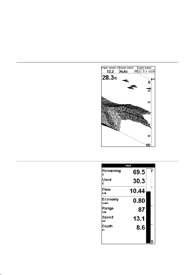
5-6 A-Scope persp ective view
The strength of echoes on this view are
determined by the ’height’ of the echo shown on
the screen.
5-7 Fuel display (443df only)
To show the Fuel display, press DISP and select
Other Tab, select Fuel and press ENT.
There are no options.
(See section 3-3 Setup > Fuel for information
about set ting up the fuel values. If the number
of engines is set to 0, the fuel features are turned
off.)
Used shows total fuel used since this was last
reset with the Cle ar Use d command.
Remaining shows the amount of fuel
remaining in the tank(s).
Flow shows the fuel consumption per hour.
For twin engine installations, the fuel flow for
each engine is shown separately. This is useful
for checking that both engines are under the
same load.
When fishing among a school of fish and
catching them, note the fish species and the
strength of the echo that it returns on the
A-scope. Then, when that particular echo is seen
at future times on the fishfinder, it is likely to be
the same fish species.
Northstar Explorer 443d/443df Installation and Operation Manual 27
Page 28
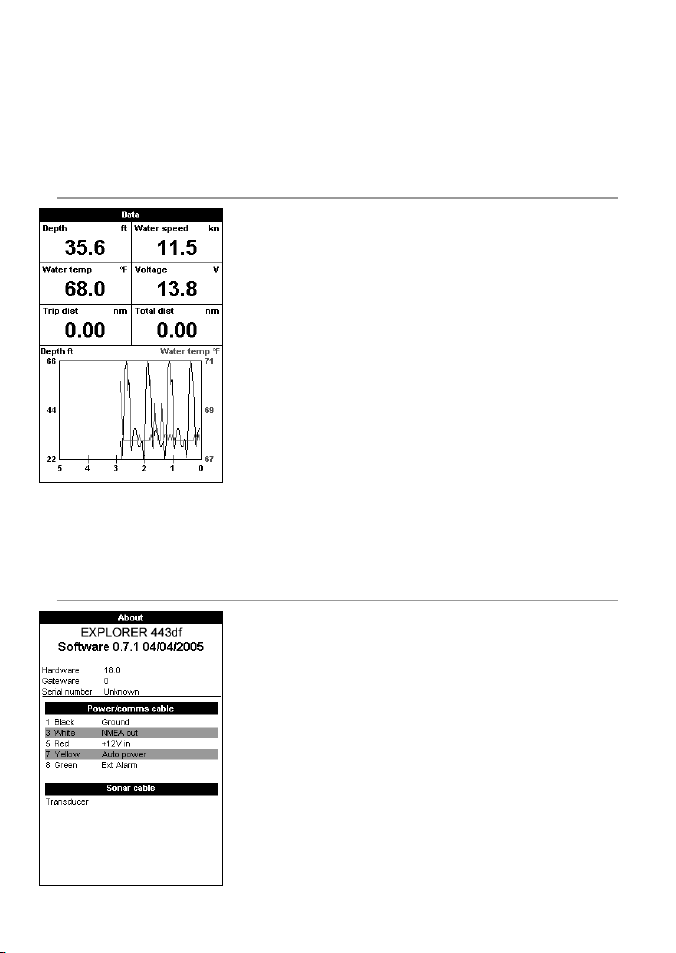
Economy is the distance travelled per unit of fuel
used. The Fishfinder calculates this using the fuel
used and boat speed (water speed or GPS speed
- which ever is selected as the speed source – see
section 3-3 Setup > Fuel).
5-8 Data dis play
To show the Data display, press DISP and select Other Tab, select
Data and press ENT.
This shows a graph of the water temperature and depth over the last
20 minutes and selected data items.
The graph is useful for locating warm and cold spots in the water.
To change data items:
1. Press MENU until the Options menu is shown.
2. Highlight Data setup and press ENT.
3. Use the cursor keys to move from data field to data field.
4. Press ENT at any data field to show the list of data items that can
be displayed there.
5. Highlight the required data item and press ENT. The data item is
immediately displayed.
6. Press ESC when finished.
Time base of graph can be changed by pressing Menu, selecting
Time Base with cursor key, pressing ENT, and selecting the required
time base from list - 5min, 10min, 20min, 1hr, 2hr.
5-9 About disp lay
To show the About display, press DISP, select Other Tab, select
About and press ENT.
There are no options.
This shows the fishfinder model number, the sof tware and hardware
versions and wiring information.
Note the sof tware version before contacting your Northstar dealer
for technical advice.
For more information on wiring, see section 6-5 Wiring options.
For more information on NMEA and NavBus, see section 6 -6 Systems
of several instruments.
The bigger this number, the bet ter the fuel
economy. Adjust the throt tle and trim to achieve
the best fuel economy.
Note: when water speed is selected as the
speed source, calibration of the boat speed
measurement is essential for an accurate fuel
economy reading – see section 3-8 Setup >
Calibrate.
Northstar Explorer 443d/443df Installation and Operation Manual28
Page 29
6 Installation and Maintenance
Correct installation is critical to the performance
of the Explorer 443d/443df. There are two
components to install, the display unit and the
Wiring Options
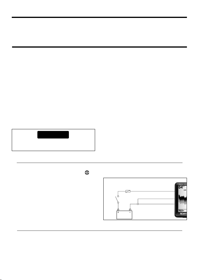
The power/data cable contains 5 wires:
Wire Function
Black Ground (power negative)
White* NMEA out
Red Positive power in, 12 V DC
Yellow Auto power in (connect to red
wire. Positive power in, to enable
Auto power).
Green* External beeper or light out,
switched to ground, 30 V DC 200
mA maximum.
Note: The cable shield is connected to Pin 1 (b lack
wire) and does not nee d to be grounded. *
Denotes Explorer 443df only.
CAUTION
1 Amp fuses must be positioned where
shown in the wiring diagrams.
Basic wiring
This requires the Explorer 443d and Explorer
443df to be powered on manually with the
key.
Black wire: Connect this to the negative battery
terminal.
Red wire: Connect this to the positive battery
terminal af ter the main switch. Fit a 1 Amp fuse
as shown.
Yel low w ire : Connect this to the black wire. This
disables the engine hours counter.
transducer. It is vital to read the entire installation
section of this manual before attempting to
install the components.
Six wiring options are described in this section:
• Basi c wiring. This does not start the
fishfinder automatically when the boat
ignition is switched on and it disables the
engine hours counter.
• Auto power wiring. This must be used for
the engine hours and fuel computer options.
• Secondary Alarm wiring
• NMEA wiring
• Single engine fuel wiring
• Twin engine fuel wiring
Note: If a wire color is not specifically m entioned, it is
not used in that wiring option.
Section 6-5 Systems of several instruments,
describes NMEA and NavBus.
Power on the fishfinder manually whenever the
main switch is on.
Basic wiring
Main
switch
Fuse
12 V DC
Red
Yellow
Black
NMEA wiring Opti on (Explorer 443df only)
White Wire: Use this, if desired, to connect the fishfinder to other NMEA instruments such as Northstar’s
Explorer R310. (See section 6 -5 Systems of several instruments.)
Northstar Explorer 443d/443df Installation and Operation Manual 29
Page 30
Secondar y alarm wiring option (E xplorer 443df only)
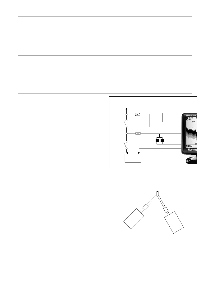
Green Wire: Use this to connect a secondar y alarm indicator such as a flashing light or external beeper
with a built-in drive circuit. See the Auto power wiring diagram.
If the external beeper or light requires more than 200 mA total, fit a relay. Consult your Northstar dealer
for more advice.
Fuel kit wiring (E xplorer 443df only)
See the Fuel K it Installation Guide for information about the fuel transducer cable.
Wire the power cable for Auto power (as described in this section) to make sure the fuel counter starts as
soon as the engine star ts.
For twin engine installation, a T-connector needs to be installed on the fuel transducer cable.
Auto power op tion
Black wire: Connect this to the negative
battery terminal.
Red wire: Connect this to the positive battery
terminal af ter the main switch. Fit a 1 Amp fuse
as shown.
Yel low w ire : To enable the engine hours counter
and fuel counter; and to star t the fishfinder
automatically when the ignition is turned on,
connect the yellow wire to the ignition system
through a 1 Amp fuse.
Note: The fishfinder cannot be tur ned off while the
ignition is on.
Auto power option
To ignitio n sys tem
Ignition
switch
Main
switch
Fuse
Fuse
External
Beeper or
12 V DC
White (NMEA out)
Yel low
Red
Green
Black
Through hull tran sducers
Speed/Temperature through hull transducer
Through hull depth transducer
Northstar Explorer 443d/443df Installation and Operation Manual30
8 pin
phono
Page 31
6-1 What comes with th is product?
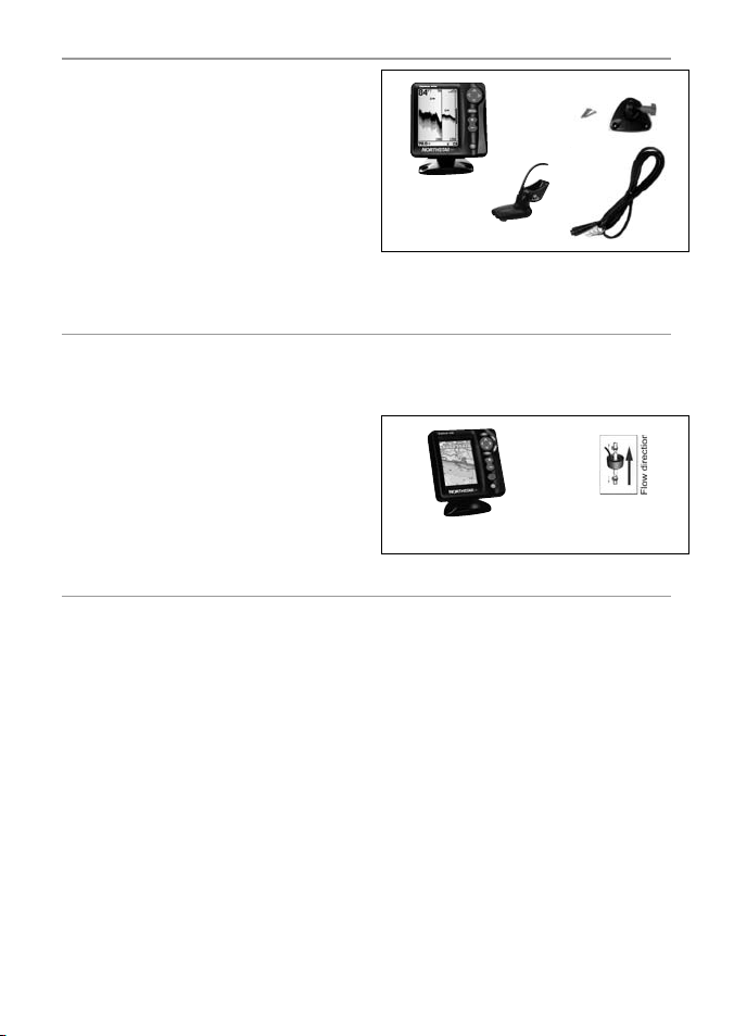
Standard configuration:
• Explorer 443d/443df display unit
• Power cable
• Mounting bracket (screws included)
• Warrant y registration card
• This manual
• Sun cover for display unit
• Flush mounting kit
• Dual frequency transom transducer (includes
cable kit and screws)
• Transom Mount Transducer Installation Manual.
6-2 Options and Acce ssories
• Explorer series of chartplotters
• Through hull dual frequenc y transducer
• Through hull speed/temperature transducer
• Fuel flow kit (single or twin engine)
• Replacement paddle wheel
• SmartCraft Gateway*
• Explorer R310 (see section 6-6 Systems of
several instruments)*
6-3 Mounting an d removing the display un it
There are two mounting arrangements:
• Flush mounting requires a solid panel
with access behind for wiring and mounting
screws. Af ter flush mounting, the Explorer
443d/443df cannot be tilted or moved after
installation to reduce any unwanted glare or
reflec tions. Carefully select the best viewing
position before installation. This would
generally be in a shaded area.
• Bracket mounting requires a panel for
mounting the bracket. Ensure that the panel
is not likely to deform and is not subjec t to
excessive vibration. The bracket can be tilted
and rotated and the Explorer 443d/443df can
be removed af ter each use.
Mounting bracket
Screws
Display unit
Dual frequency
transom transducer
Power cable
Please consult your Northstar dealer for more
information.
* Explorer 443df only
Explorer
538 chartplotter
Fuel fl ow kit
Select a position where the display unit will be:
• At least 4” (100 mm) away from the compass.
• At least 12” (300 mm) away from any radio
transmitter.
• At least 4 f t. (1.2 m) away from any antenna.
• Easy to read by the helmsman and crew while
underway.
• Protected from physical damage during
rough sea passa ges.
• Eas y to access the 12V DC power source.
• Convenient to route the transducer cables.
Northstar Explorer 443d/443df Installation and Operation Manual 31
Page 32

Flush Mountin g
1. Cut a hole in the bulkhead for the display unit
using the flush mount template.
2. Drill four holes for the mounting studs using
the flush mount template.
3. Screw the four studs into the brass inserts in
the back of the display unit.
4. Sit the display unit in place and fit the
washers and nuts to the studs.
Removing the d isplay unit
The display unit can be removed after each
use for protection against the environment or
security reasons.
When removing the display unit, ensure that
the plugs lef t in the boat are not exposed to the
elements. Push the attached dust cover over the
exposed ends of the plugs. Keep the display unit
in a dry clean place such as an optional Northstar
carry bag.
Bracket Mounting
1. Fix the mounting bracket onto the boat
using the three stainless steel screws. Do not
overtighten the screws, as the bracket may not
rotate.
2. Push the display unit onto the mounting
bracket and tighten it firmly using the knob
on the mounting bracket.
3. Attach the cables.
6-4 Systems of se veral instruments (E xplorer 443df only)
Several Nor thstar instruments can be connec ted
together to share data.
The Explorer 443d/443df is particularly suited
to work with the Explorer 538 (3.8” color)
- Northstar’s GPS char tplotters with worldwide
coverage.
There are two ways of connecting instruments
together; NavBus or NMEA.
NavBus
NavBus is a Northstar proprietary system that
allows systems of multiple instruments to be
built using a single set of transducers. When
instruments are connec ted by NavBus:
• If the units, alarms or calibration are changed
in one instrument, then the values will
automatically change in all instruments of the
same type.
• Each instrument can be assigned to a group
of instruments. Then, if the backlight setting
is changed in one group, it will automatically
• If an alarm sounds, mute it by clearing the
NMEA
NMEA is an industry standard for marine
instrument connections. Data sent by one
instrument over an NMEA line can be read and
displayed by another instrument that accepts
NMEA 0183 Version 2. It is not as flexible as
NavBus as it requires dedicated connections
between instruments.
Please contact your Northstar dealer for
information on Northstar’s full range of NMEA
enabled instruments and connec tion options.
change for the other instruments in that
group. However, the backlight setting will not
change for instruments in different groups.
alarm on any instrument which can display
that alarm.
Northstar Explorer 443d/443df Installation and Operation Manual32
Page 33
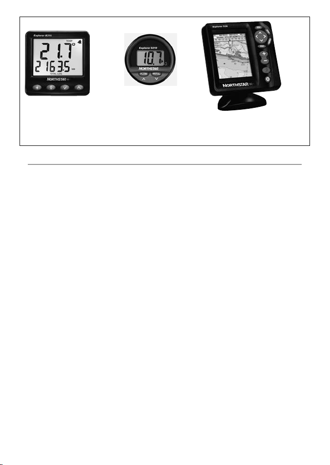
Explorer D210
Explorer R310
Repeater for depth, speed, water temperature and battery
voltage. Accepts NavBus or NMEA data inputs from other
instruments.
Depth Repeater
6-5 Cleaning a nd maintenance
To avoid damage, clean the screen only with a
damp cloth and mild detergent when dirt y or
covered in sea salt. Avoid abrasive cleaners, petrol
or other solvents.
Cover or remove a transom-mounted transducer
when repainting the hull. If painting over a
through hull transducer with antifouling paint,
use only one coat of paint. Remove the previous
coat of antifouling paint by sanding it lightly.
Explorer 538
Color GPS Char tplotter with
worldwide coverage
To optimize per forman ce, avoid w alking o n
or jamming cables and connectors. Keep the
transducer free of weed, paint and debris. Do not
use a high pressure water blast on a speed sensor
paddlewheel as it may damage the bearings.
When not in use, the Explorer 443d/443df can
be removed from the installation bracket and
stored in the Northstar carry bag, or lef t on the
installation bracket and securely covered with the
sun cover supplied.
Northstar Explorer 443d/443df Installation and Operation Manual 33
Page 34
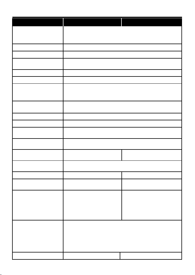
Appendix A - Specifications
Speci fications FIS H 443d FISH 443 df
Displ ay type:
Display size: 4.3 ” (110mm) d iag onal
Supply voltage: 10 to 16 V DC
Suppl y current at 13. 8 V:
Operating temperature: 32° to 122°F (0 ° to 50°C)
Environment: IPx6 and IP x7
Standards Compliance EMC:
Depth:
Output power: Variable, u p to 250W RMS
Dual Transducer frequency: 200 kHz / 83 kHz
Receiver sensitivity:
Typical depth acquisition time
from startup:
Transom transducer cable
length:
Temperature measurement
range:
Speed range: 1 to 50 kn (57.5 mph, 96.6 kp h)
Communicat ions:
NMEA Output:
NMEA (0183) is a stan dard for
interfacing marine electronic
devices. T he Northstar f ishfinder
can outpu t the following
sentences
Fuel Comp uter:*
(optiona l fuel transducer(s)
required)
*443 df o nly
SmartCraft Support: No Yes, single engine
16 Gr eysc ales
Screen Re solution 360 high x 240 wi de(pixels)
White LED backlighting
170 mA min - no backligh ting
250 mA max - ful l backlighting
USA FCC Part 15 Class B
Europe (CE ) EN60945 (EMC only)
New Zealand an d Australia (C-Tick) CISPR 22
2 ft (0. 6 m) to 750ft with suppli ed transducer.
Depth cap abilities of trans ducer used and insta llation and water clari ty.
Better th an 10 micro volt s RMS
Dynamic r ange 4.0 million to 1 (120 dB)
2 seconds at 100 f t (30 m)
33 ft (10 m) 26 ft ( 8 m)
32° to 99.9°F ( 0° to 37.7° C) Resolution o f 0.1° uni t
NMEA 0183 (Ver 2.0) 4 800 baud
NavBus
DBT (Depth Below Transducer)
DPT (Dep th and Keel offs et)
VHW (Speed)
VLW (Distan ce traveled – Total & Trip)
MTW (Sea Wa ter temperature)
XDR (Bat tery voltage and f uel flow)
Outboa rd carbureted two st roke and EFI petrol/gaso line
engines: 30 to 300 hp
Outboa rd four stroke petrol /gasoline engines: 9 0 to 300 hp
Inboard p etrol/gasoline en gines: 50 to 300 hp
Minimum f low rate: 1.3 U.S. gallo ns per hour (5 litres per h our)
Maximum f low rate: 34 U.S. ga llons per hour (130 litres per ho ur)
Northstar Explorer 443d/443df Installation and Operation Manual34
Page 35
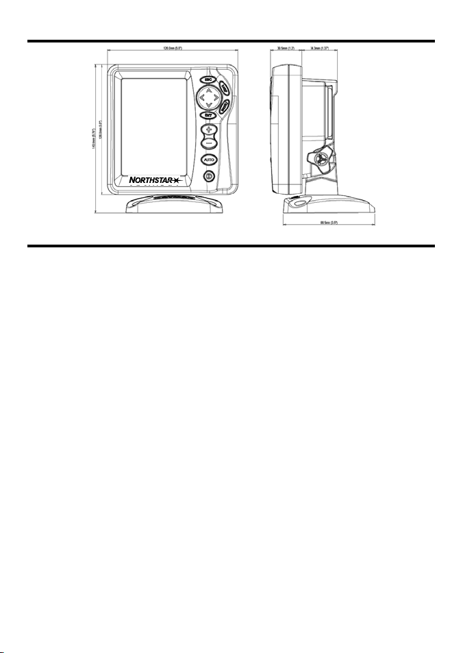
Appendix B - Dimensions
Appendix C - Troubleshooting
This troubleshooting guide is written with
the assumption that the user has read and
understood the relevant sections in this manual.
It is possible in many cases to solve difficulties
without having to send the display unit back to
the manufacturer for repair. Please follow this
troubleshooting section before contacting the
nearest Nor thstar dealer.
There are no user serviceable parts. Specialized
methods and testing equipment are required
to ensure that the display unit is reassembled
correctly and is waterproof. Users who service the
product themselves will void the warrant y.
Repairs to the product may only be carried out
by a service centre approved by Northstar. If the
product must be sent into a service centre for
repair, it is essential to send in the transducer(s) at
the same time.
More information can be found on our Website:
www.northstarnav.com.
1. The fish finder won’t turn on:
a) The Explorer 443d/443df is designed to
operate on a 12 volt battery system, where
the voltage may vary from 10 to 16 volts. If
an excessive voltage is supplied, the unit will
turn off/not start.
b) Check that the power cable connector at the
back of the display unit is securely plugged
in and the collar is locked in place. The collar
must be secure for watertight connection.
c) Measure the battery voltage while the battery
is under load - turn on some lights, radio or
other elec trical equipment connected to the
battery. If the voltage is less than 10 volts:
- the batter y terminals or wiring on the
terminals may be corroded.
- the batter y may not be charging correctly
or may need replacing.
d) Inspect the power cable from end to end for
damage such as cuts, breaks, squashed or
trapped sections.
e) Ensure that the red wire is connected to the
positive bat tery terminal and the black wire
to the negative battery terminal. If wired for
the Auto Power option, ensure the yellow
wire is connec ted to the ignition circuit. Also
check the boat’s main switch circuit (see
section 6-5 Wiring options).
f) Check for corrosion on the power cable
connector and clean or replace if required.
g) Check fuses that are placed in line with the
power cable. A fuse can be blown despite
appearing to be good or the fuse may be
corroded. Test the fuse or replace it with a
fuse known to be good.
Northstar Explorer 443d/443df Installation and Operation Manual 35
Page 36

2. The fish finder won’t turn off :
The fishfinder may have been wired for Auto
power. In this case, the fishfinder cannot be
turned of f while the ignition power is on.
(See Auto power wiring in sec tion 6-5 Wiring
options.)
3. The fishfinder operates erratically:
a) Check that the transducer does not have
debris (e.g. weed, plastic bag) caught around
it.
b) The transducer may have been damaged
during launching, running aground or while
underway with debris etc. If the transducer
has been impacted, it may have been kicked
up on the bracket. If it is not physically
damaged, reset the transducer back to its
original position. (See the Tra nsom Trans duce r
Installation Guide.)
c) When the transducer is less that 2 f t. (0.6 m)
from the bot tom, the depth readings may
become inconsistent and erratic.
d) Manual Gain may be set too low, which may
cause weak bottom echo or no fish signals. If
in Manual Gain, tr y increasing the Gain.
e) Ensure the back of the bot tom surface of the
transducer is slightly lower than the front and
the front is as deep in the water as possible
in order to minimize the generation of
bubbles through cavitation. (See the Tran so m
Transducers Installation Guide.)
f) Check the transducer and power cable
connectors at the back of the display unit
are securely plugged in and the collars are
locked in place. The collars must be secure
watertight connection.
g) Inspect the power cable from end to end for
damage such as cuts, breaks, squashed or
trapped sections.
h) Ensure there is not another fishfinder or
depth sounder turned on, which may
interfere with this fishfinder.
i) Electrical noise from the boat’s engine or
an accessor y may be interfering with the
transducer(s) and/or the Nor thstar fishfinder.
This may cause the fishfinder to automatically
decrease the Gain unless using Manual Gain.
The fishfinder thus eliminates weaker signals
such as fish or even the bottom from the
display. This may be checked by switching
off other instruments, accessories (e.g. bilge
pump) and the motor until the of fending
device is located. To stop problems from
electrical noise, try:
- re-routing the power and transducer
cable(s) away from the boat’s other
electrical wiring.
- routing the display unit’s power cable
directly to the batter y with an in-line fuse.
4. Bottom is not displayed:
a) The fishfinder may have Manual Range
selected and the depth may be outside the
range value selected. Either change the
fishfinder to Auto Range or select another
depth range (see section 4-5 Range).
b) The depth may be outside the fishfinder’s
range. While in Auto Range, the display unit
will display “--.-” to indicate that there is no
bottom detected. A display of the bottom
should reappear when in shallower water.
5. The bottom is disp layed too far up
the screen:
The fishfinder may have Manual Range
selected and the selected Range value is
too high for the depth. Either change the
for
fishfinder to Auto Range or select another
depth range (see section 4-5 Range).
6. Bottom echo disappears or erratic
digital readi ng while the boat i s moving:
a) Ensure the back of the bot tom surface of the
transducer is slightly lower than the front and
the front is as deep in the water as possible
in order to minimise the generation of
bubbles through cavitation. (See the Tran so m
Transducers Installation Guide, for more
information.)
Northstar Explorer 443d/443df Installation and Operation Manual36
Page 37

b) The transducer may be in turbulent water.
Air bubbles in the water disrupt the echoes
returned, interfering with the fishfinder’s
ability to find the bottom or other targets.
This often happens when the boat is
reversed. The transducer must be mounted
in a smooth flow of water in order for the
fishfinder to work at all boat speeds.
c) Electrical noise from the boat’s motor
can interfere with the fishfinder. Try some
suppression spark plugs.
7. If the fi shfinder beeps when t urned on
but nothing is displayed:
The fishfinder may be operating, but the
backlight settings may have been set too low.
See section 2 Basic Operation, to adjust the
fishfinder backlight. Press
twice to restore
default backlight settings.
8. The wrong language is displayed:
See section 3-1 Setup > System.
9. Fuel used or remaining seem inaccurate:
a) If the engine is run while the fishfinder is
powered of f, the fishfinder does not record
the amount of fuel used during that engine
run. Consequently, the Fuel remaining
value will be higher than the actual amount
of fuel remaining in the tank.
To avoid this problem, use the Auto Power
Wiring option describ ed in section 6-5 Wiring
options. This ensures that the fishfinder
powers on automatically whenever the boat ’s
ignition is switched on.
b) In rough seas, fuel may surge back and forth
through the fuel transducer, resulting in
incorrect readings. Try installing a one-way
valve between the fuel transducer and the
fuel tank.
c) The Set remaining fuel value must be
reset after every refuelling (see section 3-3
Setup > Fuel).
d) The fuel tank may not refill to the same
capacity each time due to air pockets.
This is particularly noticable with underfloor
tanks.
e) Fuel transducers wear out over time and
should be replaced after every 500 0 litres of
fuel.
10. Flow indic ates no fuel or low fuel:
a) Check that the number of engines is set to 1.
See section 3-3 Setup > Fuel.
b) Check that the fuel cable connectors are
securely plugged in and the collar is locked
in place. The collar must be locked in place to
give a watertight connec tion.
c) A fuel transducer may be clogged. If so,
remove the transducer from the fuel line
and gently blow through it in the opposite
direction to the fuel f low.
A fuel filter bet ween the fuel transducer and
the fuel tank must be installed as per the fuel
installation guide. Failure to do so will void
the warrant y.
d) Inspect the fuel cable from end to end for
damage such as cuts, breaks, trapped or
squashed sections.
e) Check that the fuel filter is clean.
11. A twin engin e installation shows only
one flow rate:
a) Check that the number of engines is set to 2.
See section 3-3 Setup > Fuel.
12. Erratic Fuel Flow rea dings:
a) The fuel flow transducer may have been
mounted too close to the fuel pump or may
be subject to excessive vibration. Refer to the
installation instructions supplied with the fuel
transducer.
b) Check for leaks in the fuel line or in the fuel
pickup in the tank.
c) The Flow filter value is not suitable for
the engine. Check that the value is not set
to zero, then try increasing the value until a
steady flow rate is shown. See section 3-3
Setup > Fuel.
Northstar Explorer 443d/443df Installation and Operation Manual 37
Page 38

d) A higher fuel Flow filter setting be
used on EFI (fuel injected) engines. See
section 3-3 Setup > Fuel.
13. There is no rea ding for fuel economy:
a) The boat must be travelling through the
water to generate an Economy reading.
b) Check that the paddlewheel on the
transducer is spinning freely and that the two
magnets in the paddlewheel are still
in place.
14. There is a double bottom trace
displayed:
a) The boat may be in an area that generates
shadows. See section 4-1 Interpreting the
display.
b) In shallow water, the echoes may bounce.
Reduce the gain setting (see sec tion 4- 4
Gain) and/or reduce the sonar pulse power
(see section 3-2 Setup > Sonar).
c) Decrease the Range.
15. No Sonar Display
Sonar is turned off. See Section 3-1
System > Setup.
Page 39

Page 40

AMERICAS
30 Sudbury Road,
Acton, MA 01720, USA
Ph: +1 978.897.6600
Ph: +1 800.628.4487
Fax: +1 978.897.7241
EUROPE
Unit 2, Ocean Quay,
Belvidere Rd, Southampton,
SO14 5QY, ENGLAND
Ph: +44 2380 339922
Fax: +44 2380 330345
AUSTRALIA
PO Box 479,
Gladesville, NSW 2111,
AUSTRALIA
Ph: +61 2 9879 9060
Fax: +61 2 9879 9009
www.northstarnav.com
NEW ZEALAND
PO Box 68 155,
Newton, Auckland
Auckland, NEW ZEALAND
Ph: +64 9 481 0500
Fax: +64 9 481 0590
Made in New Zealand
MN000620A-G
 Loading...