


951XD

951X/XD AND 952X/XD
GPS C
HART NAVIGATORS
INSTALLATION MANUAL
Revision C
Part Number GM1505C
Northstar Technologies
30 Sudbury Road
Acton, Massachusetts 01720
www.northstarcmc.com
Service: 978/897-0770
Sales: 978/897-6600


Limited warranty policy
Northstar Technologies, a division of BSC, Inc., warrants the Northstar
951/952 to be free from defects in materials and workmanship for a
period of two (2) years. This warranty applies to the original purchaser
and to any subsequent owner during the warranty period, which begins
on the date of shipment of the unit, F.O.B. Acton, Massachusetts, to an
authorized Northstar dealer.
Systems may not be returned to Northstar without a Returned Materials
Authorization (RMA) number. Call the Northstar dealer or Northstar for
instructions.
During the unit’s warranty period, Northstar will repair or replace, at its
option, any part of the unit it finds to be defective due to faulty mate-
rial(s) or workmanship. All such repairs and/or replacements will be
promptly performed by Northstar free-of-charge to the owner, excluding
freight costs incurred in shipping to the factory. Return shipments from
Northstar to points within the United States are made via ground trans-
portation, freight prepaid. Special shipping charges (overnight, two-day,
and so on) are the responsibility of the owner.
To be covered by this warranty, the Northstar equipment must have been
in normal use. This warranty does not apply to units with defects caused
by improper installation, physical damage, abuse, tampering, lightning or
other abnormal electrical discharge, or to units with defaced or altered
serial numbers, or to units repaired by unauthorized persons or repaired
in a manner that violates Northstar’s recommended service procedures.
All repairs and/or replacements made under this warranty must be per-
formed at Northstar’s facilities in Acton, Massachusetts. Performance of
warranty work elsewhere will not be authorized, and Northstar will not
pay for any charges for such work. Northstar will not be responsible for
payment of any charges imposed by a Northstar dealer or other party for
services requested by and/or performed for a unit’s owner in connection
with this warranty. Such services might include removal of the unit from
a vessel, inspection, packaging, handling, reinstallation, and the like.
Northstar Technologies assumes no responsibility for any consequential
losses of any nature with respect to any of its products or services sold,
rendered, or delivered. The foregoing is the only warranty expressed or
implied. No other warranty exists.


951/952 INSTALLATION MANUAL Revision C Page i
Contents
SECTION ONE - Introduction. . . . . . . . . . . . . . . . . . . . . . . . . . . . . . . . . . . . . . . . . . . . . . . . 1
Welcome . . . . . . . . . . . . . . . . . . . . . . . . . . . . . . . . . . . . . . . . . . . . . . . . . . . . . . . . . . . . . . . . . . . . . . . . . 1
Who should read this manual . . . . . . . . . . . . . . . . . . . . . . . . . . . . . . . . . . . . . . . . . . . . . . . . . . . . . . 1
Scope of this manual . . . . . . . . . . . . . . . . . . . . . . . . . . . . . . . . . . . . . . . . . . . . . . . . . . . . . . . . . . . . . . 1
Getting technical support . . . . . . . . . . . . . . . . . . . . . . . . . . . . . . . . . . . . . . . . . . . . . . . . . . . . . . . . . . 1
Servicing the unit . . . . . . . . . . . . . . . . . . . . . . . . . . . . . . . . . . . . . . . . . . . . . . . . . . . . . . . . . . . . . . . . . 2
Returning a unit for service . . . . . . . . . . . . . . . . . . . . . . . . . . . . . . . . . . . . . . . . . . . . . . . . . . . . . . . . . 3
SECTION TWO - Installing the unit . . . . . . . . . . . . . . . . . . . . . . . . . . . . . . . . . . . . . . . . . . 5
Safety considerations . . . . . . . . . . . . . . . . . . . . . . . . . . . . . . . . . . . . . . . . . . . . . . . . . . . . . . . . . . . . . .5
Ordering information . . . . . . . . . . . . . . . . . . . . . . . . . . . . . . . . . . . . . . . . . . . . . . . . . . . . . . . . . . . . . . 5
System overview . . . . . . . . . . . . . . . . . . . . . . . . . . . . . . . . . . . . . . . . . . . . . . . . . . . . . . . . . . . . . . . . . . 6
Installation considerations . . . . . . . . . . . . . . . . . . . . . . . . . . . . . . . . . . . . . . . . . . . . . . . . . . . . . . . . . .7
Choosing a system location . . . . . . . . . . . . . . . . . . . . . . . . . . . . . . . . . . . . . . . . . . . . . . . . . . . . . . . . 8
Wiring the unit . . . . . . . . . . . . . . . . . . . . . . . . . . . . . . . . . . . . . . . . . . . . . . . . . . . . . . . . . . . . . . . . . .13
Installing the antenna . . . . . . . . . . . . . . . . . . . . . . . . . . . . . . . . . . . . . . . . . . . . . . . . . . . . . . . . . . . .15
Turning the unit on and off . . . . . . . . . . . . . . . . . . . . . . . . . . . . . . . . . . . . . . . . . . . . . . . . . . . . . . .28
Testing and troubleshooting the 951/952 . . . . . . . . . . . . . . . . . . . . . . . . . . . . . . . . . . . . . . . . . . .31
SECTION THREE - Interfacing. . . . . . . . . . . . . . . . . . . . . . . . . . . . . . . . . . . . . . . . . . . . . . 39
Interfacing the unit . . . . . . . . . . . . . . . . . . . . . . . . . . . . . . . . . . . . . . . . . . . . . . . . . . . . . . . . . . . . . . .39
Configuring the NMEA output ports . . . . . . . . . . . . . . . . . . . . . . . . . . . . . . . . . . . . . . . . . . . . . . . .41
Connecting to other equipment . . . . . . . . . . . . . . . . . . . . . . . . . . . . . . . . . . . . . . . . . . . . . . . . . . . .48
Setting the anchor-watch alarm honk . . . . . . . . . . . . . . . . . . . . . . . . . . . . . . . . . . . . . . . . . . . . . . .55
Configuring the RS-232 port . . . . . . . . . . . . . . . . . . . . . . . . . . . . . . . . . . . . . . . . . . . . . . . . . . . . . . .58
Ordering 951/952 software updates . . . . . . . . . . . . . . . . . . . . . . . . . . . . . . . . . . . . . . . . . . . . . . . .60
APPENDIX A - Technical specifications . . . . . . . . . . . . . . . . . . . . . . . . . . . . . . . . . . . . 61
951/952 . . . . . . . . . . . . . . . . . . . . . . . . . . . . . . . . . . . . . . . . . . . . . . . . . . . . . . . . . . . . . . . . . . . . . . . . .61
IEC compliance . . . . . . . . . . . . . . . . . . . . . . . . . . . . . . . . . . . . . . . . . . . . . . . . . . . . . . . . . . . . . . . . . .62
Internal DGPS receiver specifications . . . . . . . . . . . . . . . . . . . . . . . . . . . . . . . . . . . . . . . . . . . . . . .62
AN150 Active GPS Antenna . . . . . . . . . . . . . . . . . . . . . . . . . . . . . . . . . . . . . . . . . . . . . . . . . . . . . . .63
8410 Antenna Coupling Unit . . . . . . . . . . . . . . . . . . . . . . . . . . . . . . . . . . . . . . . . . . . . . . . . . . . . . .63
Combination GPS/DGPS antenna . . . . . . . . . . . . . . . . . . . . . . . . . . . . . . . . . . . . . . . . . . . . . . . . . . .63

Page ii 951/952 INSTALLATION MANUAL Revision C

951/952 INSTALLATION MANUAL Revision C Page iii
Figures
Figure 1: 951/952 dimensions (side) . . . . . . . . . . . . . . . . . . . . . . . . . . . . . . . . . . . . . . . . . . . . . . . . . . . . . . . . 9
Figure 2: 951/952 dimensions (front) . . . . . . . . . . . . . . . . . . . . . . . . . . . . . . . . . . . . . . . . . . . . . . . . . . . . . .10
Figure 3: Yoke mount drilling dimensions . . . . . . . . . . . . . . . . . . . . . . . . . . . . . . . . . . . . . . . . . . . . . . . . .11
Figure 4: Flush mount drilling dimensions . . . . . . . . . . . . . . . . . . . . . . . . . . . . . . . . . . . . . . . . . . . . . . . . .12
Figure 5: Rear connectors . . . . . . . . . . . . . . . . . . . . . . . . . . . . . . . . . . . . . . . . . . . . . . . . . . . . . . . . . . . . . . . .14
Figure 6: Separation distances between antennas . . . . . . . . . . . . . . . . . . . . . . . . . . . . . . . . . . . . . . . . . . .16
Figure 7: GPS-only antenna (AN150) . . . . . . . . . . . . . . . . . . . . . . . . . . . . . . . . . . . . . . . . . . . . . . . . . . . . . .18
Figure 8: Stripping the coax cable jacket . . . . . . . . . . . . . . . . . . . . . . . . . . . . . . . . . . . . . . . . . . . . . . . . . . .19
Figure 9: Flared cable braid . . . . . . . . . . . . . . . . . . . . . . . . . . . . . . . . . . . . . . . . . . . . . . . . . . . . . . . . . . . . . .19
Figure 10: Completed BNC connector . . . . . . . . . . . . . . . . . . . . . . . . . . . . . . . . . . . . . . . . . . . . . . . . . . . . .20
Figure 11: Combo GPS/DGPS antenna (AN205-P) . . . . . . . . . . . . . . . . . . . . . . . . . . . . . . . . . . . . . . . . . . .20
Figure 12: Correct AN205-P (combo antenna) splitter wiring . . . . . . . . . . . . . . . . . . . . . . . . . . . . . . . . .21
Figure 13: Stripping the coax cable jacket . . . . . . . . . . . . . . . . . . . . . . . . . . . . . . . . . . . . . . . . . . . . . . . . . .22
Figure 14: Flared cable braid . . . . . . . . . . . . . . . . . . . . . . . . . . . . . . . . . . . . . . . . . . . . . . . . . . . . . . . . . . . . .22
Figure 15: Completed TNC connector . . . . . . . . . . . . . . . . . . . . . . . . . . . . . . . . . . . . . . . . . . . . . . . . . . . . .22
Figure 16: ACU assembly . . . . . . . . . . . . . . . . . . . . . . . . . . . . . . . . . . . . . . . . . . . . . . . . . . . . . . . . . . . . . . . .23
Figure 17: Correct AN150 and 8410 wiring . . . . . . . . . . . . . . . . . . . . . . . . . . . . . . . . . . . . . . . . . . . . . . . .24
Figure 18: PL 259 (UHF) connector . . . . . . . . . . . . . . . . . . . . . . . . . . . . . . . . . . . . . . . . . . . . . . . . . . . . . . . .26
Figure 19: Proper insertion of a chart cartridge . . . . . . . . . . . . . . . . . . . . . . . . . . . . . . . . . . . . . . . . . . . . .29
Figure 20: Interface connector (as viewed from back of unit) . . . . . . . . . . . . . . . . . . . . . . . . . . . . . . . . .40
Figure 21: 200 PPNM output . . . . . . . . . . . . . . . . . . . . . . . . . . . . . . . . . . . . . . . . . . . . . . . . . . . . . . . . . . . . .41
Figure 22: Aux port interface diagram (wiring side view, solder cup) . . . . . . . . . . . . . . . . . . . . . . . . . .51
Figure 23: Pin 14 honk alarm interface . . . . . . . . . . . . . . . . . . . . . . . . . . . . . . . . . . . . . . . . . . . . . . . . . . . .56

Page iv 951/952 INSTALLATION MANUAL Revision C

951/952 INSTALLATION MANUAL Revision C Page v
Tables
Table 1: Contacting Northstar . . . . . . . . . . . . . . . . . . . . . . . . . . . . . . . . . . . . . . . . . . . . . . . . . . . . . . . . . . . . . 2
Table 2: Troubleshooting the installation . . . . . . . . . . . . . . . . . . . . . . . . . . . . . . . . . . . . . . . . . . . . . . . . . . 31
Table 3: Troubleshooting the GPS/DGPS antenna installation . . . . . . . . . . . . . . . . . . . . . . . . . . . . . . . . 35
Table 4: Interface connector pins . . . . . . . . . . . . . . . . . . . . . . . . . . . . . . . . . . . . . . . . . . . . . . . . . . . . . . . . . 40
Table 5: Port setup options. . . . . . . . . . . . . . . . . . . . . . . . . . . . . . . . . . . . . . . . . . . . . . . . . . . . . . . . . . . . . . . 42
Table 6: 0183 sentence identifiers. . . . . . . . . . . . . . . . . . . . . . . . . . . . . . . . . . . . . . . . . . . . . . . . . . . . . . . . . 44
Table 7: Connecting to an external Northstar beacon receiver . . . . . . . . . . . . . . . . . . . . . . . . . . . . . . . . 52
Table 8: Connection to Northstar 800 port A . . . . . . . . . . . . . . . . . . . . . . . . . . . . . . . . . . . . . . . . . . . . . . . 54
Table 9: Connection to Northstar 800 port B . . . . . . . . . . . . . . . . . . . . . . . . . . . . . . . . . . . . . . . . . . . . . . . 54
Table 10: Northstar 800 series output port setup . . . . . . . . . . . . . . . . . . . . . . . . . . . . . . . . . . . . . . . . . . . 54
Table 11: Yeoman plotter setup with the unit . . . . . . . . . . . . . . . . . . . . . . . . . . . . . . . . . . . . . . . . . . . . . . 55
Table 12: Beep and honk settings for all alarms . . . . . . . . . . . . . . . . . . . . . . . . . . . . . . . . . . . . . . . . . . . . . 57
Table 13: Standards for IEC compliance . . . . . . . . . . . . . . . . . . . . . . . . . . . . . . . . . . . . . . . . . . . . . . . . . . . 62

Page vi 951/952 INSTALLATION MANUAL Revision C

SECTION ONE - Introduction
951/952 INSTALLATION MANUAL Revision C Page 1
SECTION ONE - Introduction
Welcome
The Northstar 951/952 Installation Manual describes how to install,
interface, and troubleshoot the Northstar 951 and 952 GPS chart naviga-
tors. Also described are the physical, mechanical, and electrical character-
istics of each unit.
For complete details about operating the unit, see the Northstar 951/952
Operator’s Manual (part number GM1500C).
The terms “unit” and “951/952” are used throughout this manual to refer
to both the 951 and 952 GPS chart navigators. The 952 features a color
display, but is otherwise identical to the 951, except where noted. The
951X and 952X are both differential-ready so you can interface them to
an external differential receiver. The 951XD and 952XD have built-in dif-
ferential receivers. Unless specifically indicated, all information in this
manual refers to both the X (non-differential) and XD (differential) ver-
sions of the unit.
Who should read this manual
The Northstar 951/952 Installation Manual is intended for marine techni-
cians who are configuring and installing either 951 or 952 GPS chart nav-
igators.
Scope of this manual
In this manual, you’ll find information about the following:
• mounting and wiring the unit
• installing the antenna
• testing and troubleshooting the unit
• configuring the NMEA output ports
• configuring the RS-232 port
• connecting two units to share waypoints and routes
• technical specifications
The rest of this particular chapter explains how to obtain technical sup-
port and how to return a unit for factory service.
Getting technical support
After you’ve followed the instructions in this installation guide, if you
need additional technical support or have any other service-related ques-
tions, you can contact either your dealer or the Northstar Service Depart-
ment. Northstar’s Service Department can be reached by email, fax, U.S.

SECTION ONE - Introduction
Page 2 951/952 INSTALLATION MANUAL Revision C
mail, or phone as described in the table below. Whether you send an
email or fax, or write or phone, please have the unit’s serial number avail-
able, and be as complete and accurate as possible when describing the
problem so that a service technician can research the problem and pro-
vide the quickest possible response.
Northstar’s Service Department is available between 9:00 AM and 5:00
PM Eastern Time, Monday through Friday, excluding major holidays.
Table 1: Contacting Northstar
Hearing from you
Your feedback is important and helps Northstar ensure that this manual
is a valuable resource for all marine technicians. Send your questions,
comments, or suggestions about this manual to:
service@northstarcmc.com
Servicing the unit
Repair of the unit is performed only at the Northstar factory. Service
includes a complete hardware and software check-out.
For a system under warranty, shipping charges to the factory are the only
cost for factory repair. Repaired units will be returned via prepaid econ-
omy ground freight (units returned overseas are chargeable).
Units and accessories returned for warranty repair that are determined to
be without fault are subject to a handling charge.
Email:
Service: service@northstarcmc.com
Sales: sales@northstarcmc.com
Fax:
Service: 978/897-1595
Sales: 978/897-7241
Telephone:
Main number: 978/897-6600 or 800/628-4487
Sales: 978/897-0770
Service: 978/897-6600
U.S. mail:
30 Sudbury Road
Acton, MA 01720
Website:
www.northstarcmc.com (you can send email to
Northstar directly from this site)
You can email the North-
star Service Department
directly from Northstar’s
website. The address is
www.northstarcmc.com.
Here, you also can
access additional techni-
cal information under
either the Manuals or
Support links.
NOTE:
Field repairs are not authorized and will void the warranty!

SECTION ONE - Introduction
951/952 INSTALLATION MANUAL Revision C Page 3
Returning a unit for service
The unit is covered by a two-year hardware-only warranty, which, in
summary, states that if the unit is returned to the factory by the owner or
dealer during the warranty period, Northstar will repair or replace, free of
charge, any part found to be defective due to faulty materials or work-
manship if the system has been properly installed and hasn’t been
abused. See the Limited Warranty Policy at the front of this manual for
further details. The only cost to the owner will be the one-way shipping
charges and any associated charges that may be imposed by the dealer. If
you have overnight or second-day shipping requirements, before ship-
ping the unit, please call the factory for turnaround time, freight charges,
and payment arrangements.
The unit should be shipped only in a properly designed carton with pack-
ing material. Shipments to the Northstar factory should be made to the
following address:
Northstar Technologies
Service Department
30 Sudbury Road
Acton, MA 01720 USA
CAUTION!
You may want to back-up any user-defined waypoints and
routes before returning the unit for repair; see the Northstar
951/952 Operator’s Manual for information on customizing the
unit.
Before returning the
unit to the Northstar
factory, to prevent
delays it is critical
that you first obtain
a Return Materials
Authorization (RMA)
number from the
Northstar Service
Department. If you
purchased your unit
through a dealer, call
the dealer with your
serial number so
they can give you an
RMA number.
Shipments without a
proper RMA number
will not be accepted!

SECTION ONE - Introduction
Page 4 951/952 INSTALLATION MANUAL Revision C
SECTION TWO - Installing the unit
951/952 INSTALLATION MANUAL Revision C Page 5
SECTION TWO - Installing the unit
This chapter includes all the information needed to install the unit. It
begins with a review of the system components and then provides infor-
mation on basic installation and powering on the unit. The rest of this
chapter describes how to wire the unit, install the antenna, and trouble-
shoot. Proper installation of the Northstar 951/952 is of utmost impor-
tance to accurately receive and effectively use GPS signals under a wide
variety of weather conditions.
Safety considerations
Ordering information
To order spare parts or replacement/missing parts, call the Northstar Sales
Department at 978-897-0770.
WARNING!
Be sure to turn the power off at the main switchboard before starting the
installation. Further, it is highly recommended that you post a notice by this
switch telling others to keep power off while you’re performing the installa-
tion. If power is left on or turned on during the installation, then fire, electri-
cal shock, or other serious injury may occur.
CAUTION!
Be sure to ground the equipment in order to prevent electrical shock and
mutual interference.
Be sure that the voltage of the power supply is compatible with the unit’s
voltage rating, which can be found on the label at the rear of the unit. Con-
necting to the wrong power supply can result in fire or damage to the
equipment.
Be sure to use the proper fuse. Using the incorrect fuse can result in fire or
damage to the unit.
Keep the following safe compass distance from the unit: 1.0m standard,
0.8m steering.
Be sure that the 951/952 doesn’t interfere with any of the on-board sys-
tems. Check all other systems to ensure that their performance doesn’t
degrade when the unit is turned on.

SECTION TWO - Installing the unit
Page 6 951/952 INSTALLATION MANUAL Revision C
System overview
The unit is shipped ready to install and operate (however, you’ll need spe-
cial tools for assembling the coaxial cable connectors; see “Mounting the
AN150 antenna” on page 18.)
It is recommended that you follow the steps below:
1. Check the shipping carton for any damage, and immediately report
any damage to the carrier. Save all packing material in case you have
to return the unit to the factory for repair or evaluation.
2. Unpack the carton, and compare its contents with those on the pack-
ing list and what you ordered.
The shipping carton contains:
• the Northstar 951X/XD or 952X/XD
• yoke-mount kit
• flush-mount gasket
• GPS antenna
• 50-foot coaxial antenna cable
• for units with an internal differential beacon receiver: an 8410
Antenna Coupling Unit (ACU); or, an AN205-P combination GPS/
DGPS antenna
• 10-foot interface cable
• 10-foot power cable
• flush-mount drilling template
• connectors and parts kit
• sunshield
• Northstar 951XD/952XD Installation Manual
• Northstar 951XD/952XD Operator’s Manual
3. After reviewing the components, next, review the components of a
proper installation. For details, see “Ensuring a proper installation”
below.
4. Select the desired unit mounting location. For details, see ”Choosing
a system location” beginning on page 8.
5. Select the desired antenna mounting location. For details, see
”Installing the antenna” beginning on page 15.
6. Make the appropriate power wiring connections. For details, see
”Wiring the unit” beginning on page 13.
7. Turn on the unit. For details, see ”Turning the unit on and off” begin-
ning on page 28.
8. To ensure that the system is running properly, perform a functional
test. For details, see ”Testing and troubleshooting the 951/952”
beginning on page 31.
9. If desired, interface the NMEA output ports; for details, see ”Config-
uring the NMEA output ports” beginning on page 41. If desired,
interface the RS-232 port; for details, see ”Configuring the RS-232
port” beginning on page 58.

SECTION TWO - Installing the unit
951/952 INSTALLATION MANUAL Revision C Page 7
Installation considerations
Ensuring a proper
installation
To ensure a proper installation, it is highly recommended that you per-
form all of the following activities before starting the installation:
• preview/survey the vessel’s layout and existing equipment
• review all the installation materials
• review all the installation requirements, including:
- the physical requirements (spacing, location with regard to other
equipment, etc.)
- the electrical and electronic requirements (interference between
other pieces of equipment, power requirements, etc.)
Although the unit itself is very straightforward and easy to understand, it
has a few basic requirements that must be met before safe and proper
operation can be assured. The major parts of the rest of this section
address several topics regarding the minimum installation requirements
for the unit, in order to:
• minimize electrical wiring hazards
• accurately receive GPS signals
• navigate safely
Bench-testing the
unit
Northstar recommends that you bench-test the unit before installing it on
the vessel. Bench-testing ensures that the equipment is fully operational,
and allows the GPS receiver to collect its almanac and ephemeris data for
the installed location, which results in less on-board installation time.
Using the AN150
GPS antenna
The GPS antenna is best mounted in the clear, and low on the vessel to
avoid extra motion from pitching and rolling. It should be mounted lower
than directional high-power transmitting antennas such as radar or sat-
com. The length of coaxial cable to the “active” AN150 antenna (supplied
with the unit) must be a minimum of 20 feet, but not more than 100 feet.
Coil up any unused length of cable; do not cut it to less than 20 feet! Be
sure that all cable connectors are securely fastened, and that the cable
itself is not subject to any tight bends.
For complete details on the AN150, see ”Choosing an antenna location”
starting on page 15.
CAUTION!
The following basic setup information isn’t a substitute for all
the details in SECTION TWO. To ensure that you meet all crit-
ical installation parameters, be sure to read and follow all of
the requirements.

SECTION TWO - Installing the unit
Page 8 951/952 INSTALLATION MANUAL Revision C
Using DGPS with an
AN150 and 8410
ACU
If the unit is equipped with a differential receiver (and you’re using the
AN150 GPS antenna, not the AN205-P GPS/DGPS combo antenna), this
receiver must be connected to a Northstar 8410 differential Antenna
Coupling Unit (ACU). The ACU’s four-foot whip antenna should be
mounted as high as conveniently possible—but not at the highest
point—and as far away as possible from other antennas. The ACU can be
mounted on a standard marine antenna mount (1" diameter, 14 threads
per inch).
For complete details on the AN150/8410 ACU mounting requirements,
see ”Installing an 8410 ACU (for use with the AN150 only)” starting on
page 23.
Using the AN205-P
DGPS antenna
For details on the DGPS antenna’s mounting requirements, see ”Choosing
an antenna location” starting on page 15.
Choosing a system location
The 951/952 unit houses the GPS receiver, optional differential receiver,
computer, power supply, lights, controls and the specially-coated display
screen. The mounting location should be chosen carefully before any
drilling or cutting takes place: Choose a mounting location that allows
good visibility of the unit’s screen, is within comfortable reach, and pro-
vides a reasonably direct path for running the required electrical cabling.
Be sure you have easy access to the control panel’s keys and that the dis-
play can be clearly seen from the normal vantage point when the user is
navigating. Even though the display screen contains an effective
anti-reflective coating, choose a location that will minimize glare from
windows or other bright objects. Although the 952 is direct-sunlight
viewable, for optimal viewing it is recommended that you install the 952
in a location that’s out of direct sunlight.
Although the unit itself is waterproof, the connectors at the back of the
unit aren’t immune to corrosion from saltwater spray. Protect the unit
from prolonged exposure to the elements by mounting it in a relatively
dry area, if possible. At the end of the day, the unit can be wiped off with
a damp cloth. When not in use, the unit should be covered with the sun-
shield to protect it from excessive heat.
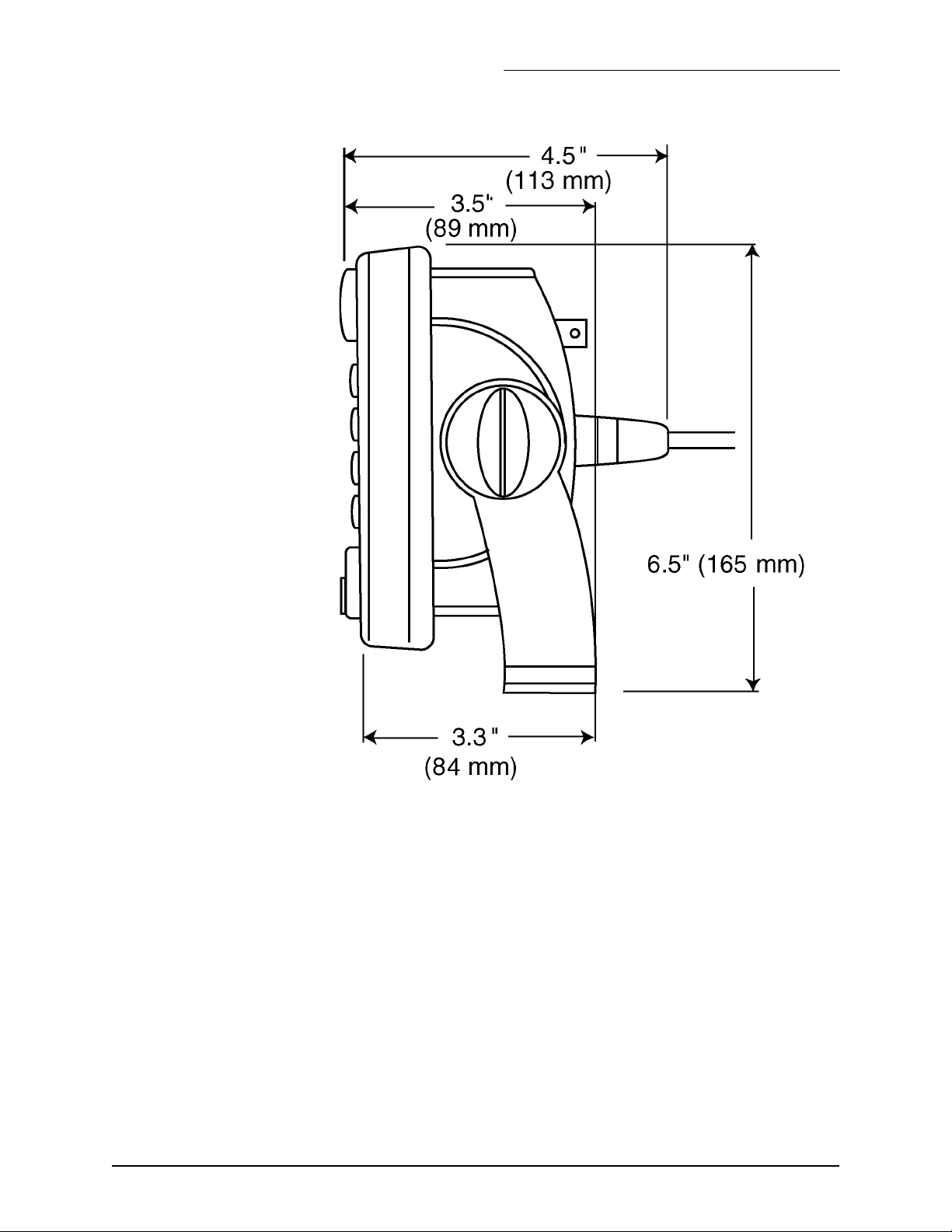
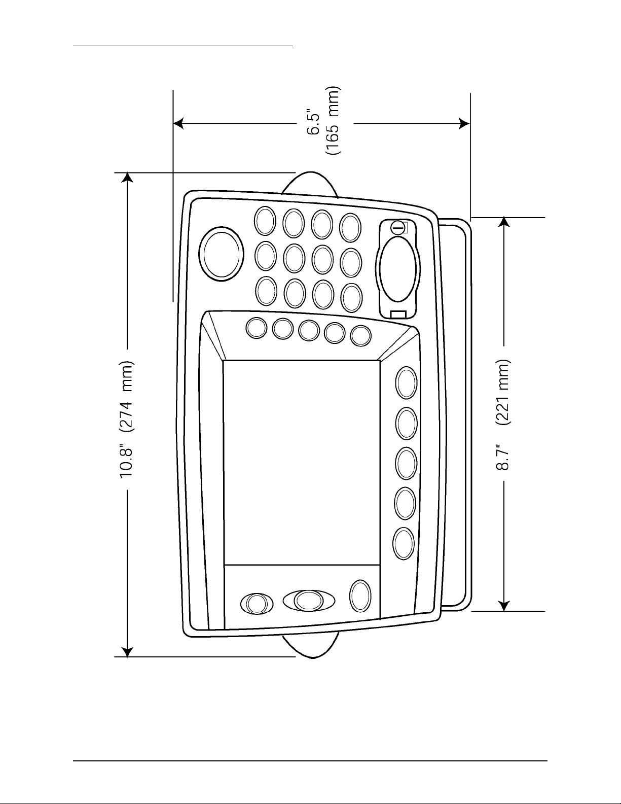
To help plan the installation, see Figure 1: ”951/952 dimensions (side),”
below and Figure 2: ”951/952 dimensions (front),” below.
SECTION TWO - Installing the unit
951/952 INSTALLATION MANUAL Revision C Page 9
Figure 1: 951/952 dimensions (side)
SECTION TWO - Installing the unit
Page 10 951/952 INSTALLATION MANUAL Revision C
Figure 2: 951/952 dimensions (front)
SECTION TWO - Installing the unit
951/952 INSTALLATION MANUAL Revision C Page 11
Flush and
yoke-mounting
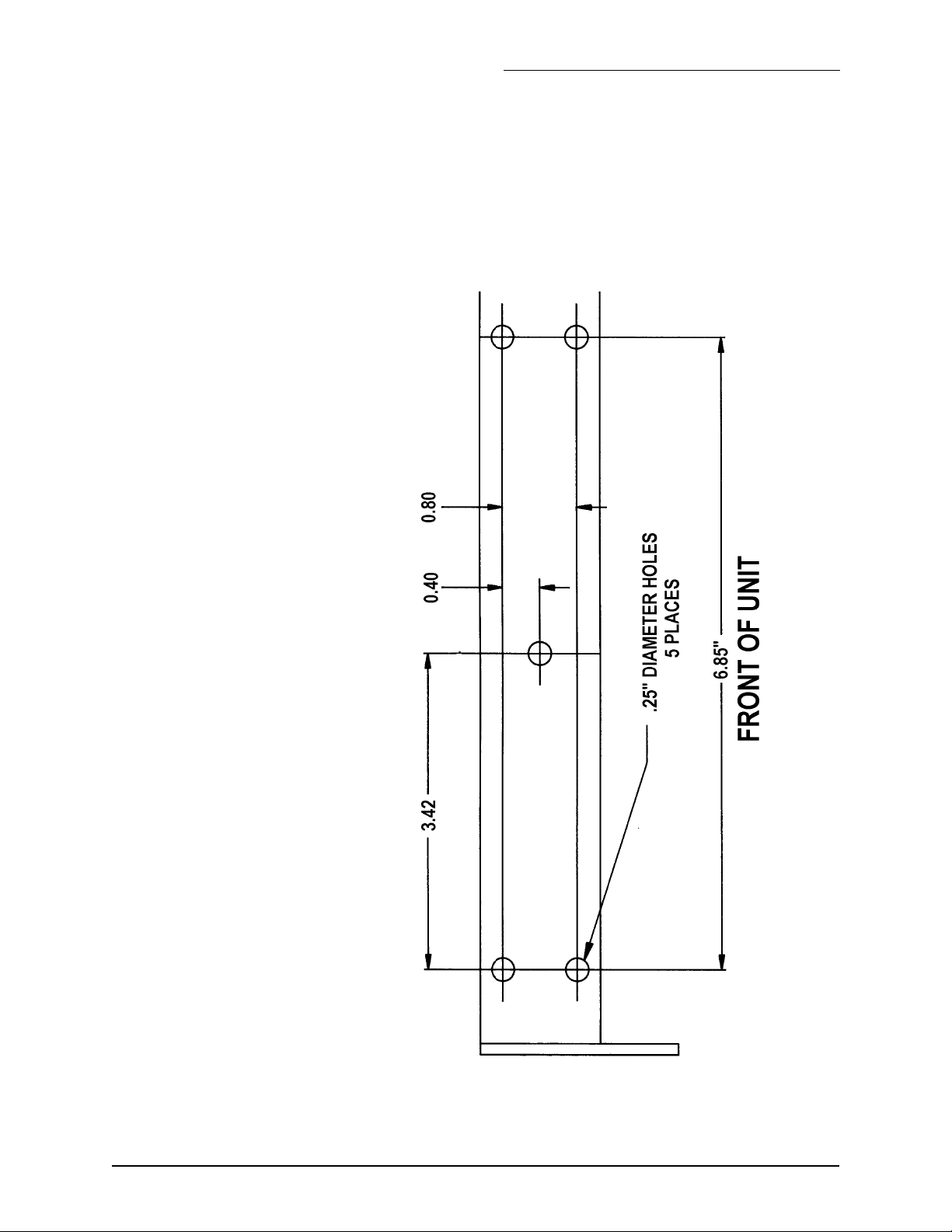
Whether you’re flush- or yoke-mounting the unit, allow at least 2½-inch
clearance at the rear for cables and connectors. For yoke mounting, leave
ample room (usually two inches) all around the sides and top to avoid
crowding the unit. For the recommended drilling dimensions, see
Figure 3 below. Before drilling holes, rotate the unit to the desired angle
to ensure proper clearance for cables and operation of the unit.
Figure 3: Yoke mount drilling dimensions
SECTION TWO - Installing the unit
Page 12 951/952 INSTALLATION MANUAL Revision C
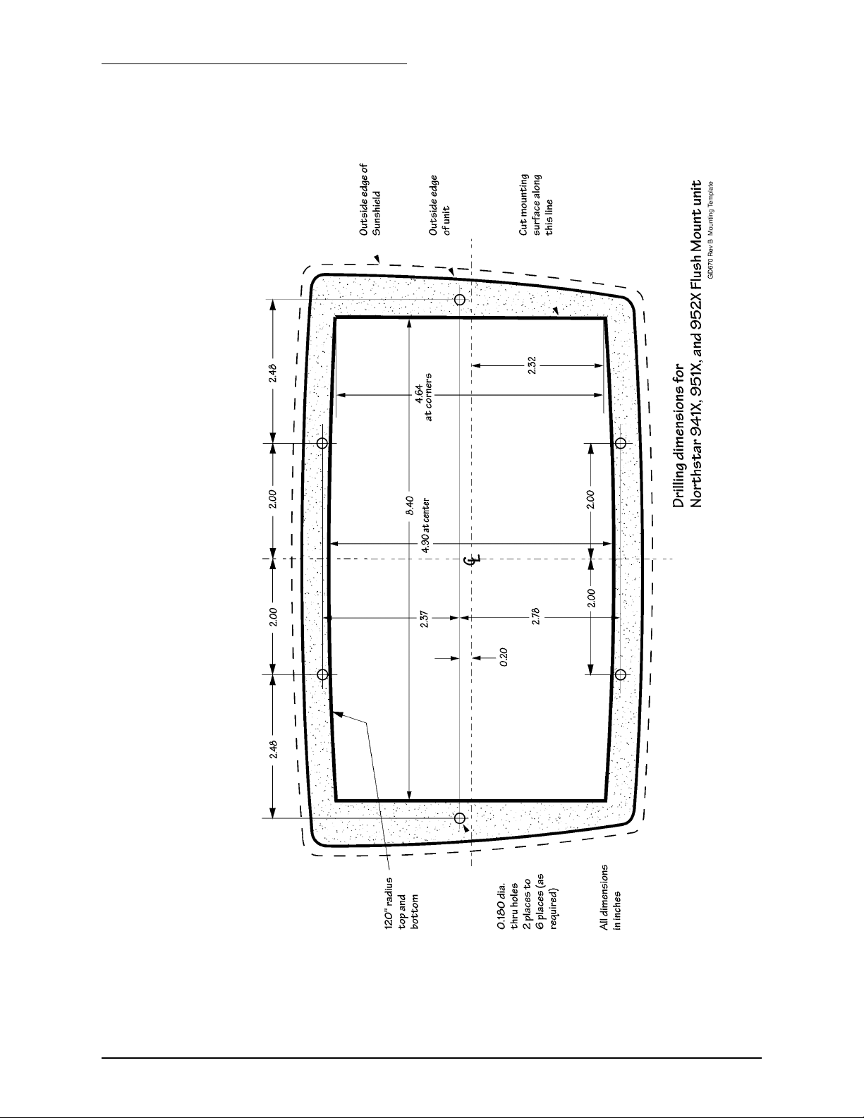
For the recommended flush mounting drilling dimensions, see Figure 4
below.
Figure 4: Flush mount drilling dimensions
SECTION TWO - Installing the unit
951/952 INSTALLATION MANUAL Revision C Page 13
Wiring the unit
The majority of installation problems are caused by shortcuts taken with
system cables. When installing the unit, be sure that you:
• assemble connectors carefully
• don’t make sharp bends
• leave service and drip loops
• tie-wrap all cables to keep them secure
• if cables are shortened, lengthened, or re-terminated, seal all wiring
splices
The unit should be connected to a source of 10- to 40-volt electrical
power, using at least 16-gauge wire. A 10-foot fused power cable is sup-
plied with the unit, and should be long enough for most installations. If it
is necessary to lengthen the power cable, however, you may extend it to a
maximum of 25 feet (using at least 14-gauge wire for runs over 15 feet)
without adversely affecting the operation of the unit.
Electrical power
requirements
The unit is a negative-ground system that is reverse-polarity protected;
an external fuse prevents damage to sensitive components.
The wires in the 10-foot power cable must be connected as follows (black
and white can be connected together at the power source):
• Red → Positive(+) (fused lead)
• Black → Negative(–)
• White → Ground (earth)
CAUTION!
When flush-mounting, be sure to mount the unit on a flat sur-
face. Mounting on a curved surface can distort or break the
plastic and cause a breech in the waterproof seal. Do not over-
tighten as case damage may occur and waterproof integrity
may be compromised. This will void the warranty due to physi-
cal damage.
CAUTION!
Ensure that fuse or circuit-breaker protection is provided at the
power source.
NOTE:
If a noise-free earth grounding point isn’t available, the white
wire should be capped and insulated. It shouldn’t be used
when an earth ground isn’t available.
SECTION TWO - Installing the unit
Page 14 951/952 INSTALLATION MANUAL Revision C
• 14-gauge connecting wire (recommended for runs of 15 feet or
more)
• 16-gauge minimum allowed for runs up to 15 feet
Northstar strongly recommends as a good safety practice that the unit be
connected to an external circuit breaker or 3-amp fuse located near the
battery or breaker box. The internal fuse is designed to protect the unit
itself; the external fuse or breaker is intended to protect the vessel wiring
and prevent electrical fires. The power wiring should be connected
directly to the battery when possible for optimum noise immunity.
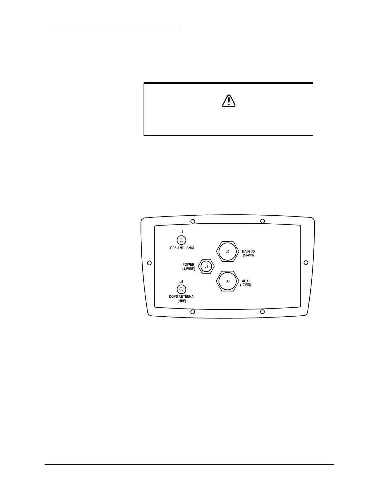
Figure 5: Rear connectors
• J1 - Power Connector (3-wire)
• J2 - Main I/O Interface Connector (18-wire)
• J3 - Auxiliary (10-wire)
• J4 - GPS Antenna Connector (BNC)
• J5 - DGPS Antenna Connector (UHF)
Internal fuse
The unit is designed with an internal fusible link to protect against faulty
power wiring. The link consists of a short length of 30 AWG wire located
on the I/O circuit board.
CAUTION!
The unit requires the following DC power:
• 10–40VDC
• negative ground only
 Loading...