

Page 1

957 GPS/W
AAS
C
HART
N
AVIGATOR
I
NSTALLATION
Revision C1
Part Number GM957IM
M
ANUAL
Northstar Technologies
30 Sudbury Road
Acton, Massachusetts 01720
800/628-4487
978/897-6600
www.northstarcmc.com
Page 2

Limited warranty policy
Northstar Technologies, Inc. warrants the Northstar 957 to be free from defects in materials and
workmanship for a period of two (2) years. This warranty applies to the original purchaser and to any
subsequent owner during the warranty period, which begins on the date of shipment of the unit,
F.O.B. Acton, Massachusetts, to an authorized Northstar dealer.
Systems may not be returned to Northstar without a Returned Materials Authorization (RMA) number. Call the Northstar dealer or Northstar for instructions.
During the unit’s warranty period, Northstar will repair or replace, at its option, any part of the unit it
finds to be defective due to faulty material(s) or workmanship. All such repairs and/or replacements
will be promptly performed by Northstar free-of-charge to the owner, excluding freight costs
incurred in shipping to the factory. Return shipments from Northstar to points within the United
States are made via ground transportation, freight prepaid. Special shipping charges (overnight,
two-day, and so on) are the responsibility of the owner.
To be covered by this warranty, the Northstar equipment must have been in normal use. This warranty does not apply to units with defects caused by improper installation, physical damage, abuse,
tampering, lightning or other abnormal electrical discharge, or to units with defaced or altered serial
numbers, or to units repaired by unauthorized persons or repaired in a manner that violates Northstar’s recommended service procedures.
All repairs and/or replacements made under this warranty must be performed at Northstar’s facilities
in Acton, Massachusetts. Performance of warranty work elsewhere will not be authorized, and Northstar will not pay for any charges for such work. Northstar will not be responsible for payment of any
charges imposed by a Northstar dealer or other party for services requested by and/or performed for
a unit’s owner in connection with this warranty. Such services might include removal of the unit
from a vessel, inspection, packaging, handling, reinstallation, and the like.
Northstar Technologies assumes no responsibility for any consequential losses of any nature with
respect to any of its products or services sold, rendered, or delivered. The foregoing is the only warranty expressed or implied. No other warranty exists.
Page 3

Contents
SECTION ONE: Introduction . . . . . . . . . . . . . . . . . . . . . . . . . . . . . . . . . . . . . . . . . . . . . . . . 1
Welcome to the Northstar 957 . . . . . . . . . . . . . . . . . . . . . . . . . . . . . . . . . . . . . . . . . . . . . . . . . . . . . . 1
Who should read this manual . . . . . . . . . . . . . . . . . . . . . . . . . . . . . . . . . . . . . . . . . . . . . . . . . . . . . . 1
Scope of this manual . . . . . . . . . . . . . . . . . . . . . . . . . . . . . . . . . . . . . . . . . . . . . . . . . . . . . . . . . . . . . . 2
Major installation steps . . . . . . . . . . . . . . . . . . . . . . . . . . . . . . . . . . . . . . . . . . . . . . . . . . . . . . . . . . . . 2
SECTION TWO: Installing and wiring the 957 . . . . . . . . . . . . . . . . . . . . . . . . . . . . . . . 5
Safety considerations . . . . . . . . . . . . . . . . . . . . . . . . . . . . . . . . . . . . . . . . . . . . . . . . . . . . . . . . . . . . . . 5
Bench-testing the 957 . . . . . . . . . . . . . . . . . . . . . . . . . . . . . . . . . . . . . . . . . . . . . . . . . . . . . . . . . . . . . 6
Mounting the 957 . . . . . . . . . . . . . . . . . . . . . . . . . . . . . . . . . . . . . . . . . . . . . . . . . . . . . . . . . . . . . . . . . 6
Wiring the 957 . . . . . . . . . . . . . . . . . . . . . . . . . . . . . . . . . . . . . . . . . . . . . . . . . . . . . . . . . . . . . . . . . . .13
SECTION THREE: Installing and wiring the 2201 . . . . . . . . . . . . . . . . . . . . . . . . . . . 17
Introducing the 2201 . . . . . . . . . . . . . . . . . . . . . . . . . . . . . . . . . . . . . . . . . . . . . . . . . . . . . . . . . . . . .17
Installing the 2201 . . . . . . . . . . . . . . . . . . . . . . . . . . . . . . . . . . . . . . . . . . . . . . . . . . . . . . . . . . . . . . .18
Wiring the 2201 . . . . . . . . . . . . . . . . . . . . . . . . . . . . . . . . . . . . . . . . . . . . . . . . . . . . . . . . . . . . . . . . .21
SECTION FOUR: Installing and wiring the 2701 . . . . . . . . . . . . . . . . . . . . . . . . . . . . 25
Introducing the 2701 . . . . . . . . . . . . . . . . . . . . . . . . . . . . . . . . . . . . . . . . . . . . . . . . . . . . . . . . . . . . .25
Installing the 2701 . . . . . . . . . . . . . . . . . . . . . . . . . . . . . . . . . . . . . . . . . . . . . . . . . . . . . . . . . . . . . . .26
Wiring the 2701 . . . . . . . . . . . . . . . . . . . . . . . . . . . . . . . . . . . . . . . . . . . . . . . . . . . . . . . . . . . . . . . . .27
Installing the AN205-P antenna . . . . . . . . . . . . . . . . . . . . . . . . . . . . . . . . . . . . . . . . . . . . . . . . . . . .28
SECTION FIVE: Checking out the system . . . . . . . . . . . . . . . . . . . . . . . . . . . . . . . . . . . 31
Inserting a chart cartridge . . . . . . . . . . . . . . . . . . . . . . . . . . . . . . . . . . . . . . . . . . . . . . . . . . . . . . . .31
Turning the 957 on and off . . . . . . . . . . . . . . . . . . . . . . . . . . . . . . . . . . . . . . . . . . . . . . . . . . . . . . . .33
Installation-test checklist . . . . . . . . . . . . . . . . . . . . . . . . . . . . . . . . . . . . . . . . . . . . . . . . . . . . . . . . . .37
SECTION SIX: Interfacing the 957 system . . . . . . . . . . . . . . . . . . . . . . . . . . . . . . . . . . 39
Wiring the connector pins . . . . . . . . . . . . . . . . . . . . . . . . . . . . . . . . . . . . . . . . . . . . . . . . . . . . . . . . .39
Configuring the NMEA output ports . . . . . . . . . . . . . . . . . . . . . . . . . . . . . . . . . . . . . . . . . . . . . . . .41
Using 200 ppnm output . . . . . . . . . . . . . . . . . . . . . . . . . . . . . . . . . . . . . . . . . . . . . . . . . . . . . . . . . . .46
Configuring the RS-232 port . . . . . . . . . . . . . . . . . . . . . . . . . . . . . . . . . . . . . . . . . . . . . . . . . . . . . . .47
Connecting the 957 to a remote display . . . . . . . . . . . . . . . . . . . . . . . . . . . . . . . . . . . . . . . . . . . . .49
Connecting the 957 to a video camera . . . . . . . . . . . . . . . . . . . . . . . . . . . . . . . . . . . . . . . . . . . . . .49
Connecting with a radar device . . . . . . . . . . . . . . . . . . . . . . . . . . . . . . . . . . . . . . . . . . . . . . . . . . . .49
Connecting two Northstar units . . . . . . . . . . . . . . . . . . . . . . . . . . . . . . . . . . . . . . . . . . . . . . . . . . . .50
Setting the anchor-watch alarm honk . . . . . . . . . . . . . . . . . . . . . . . . . . . . . . . . . . . . . . . . . . . . . . .53
Page 4

SECTION SEVEN: Troubleshooting and servicing the 957 system. . . . . . . . . . . 55
Troubleshooting 957 installation problems . . . . . . . . . . . . . . . . . . . . . . . . . . . . . . . . . . . . . . . . . .55
Getting technical support . . . . . . . . . . . . . . . . . . . . . . . . . . . . . . . . . . . . . . . . . . . . . . . . . . . . . . . . .59
Servicing the 957 system . . . . . . . . . . . . . . . . . . . . . . . . . . . . . . . . . . . . . . . . . . . . . . . . . . . . . . . . . .61
Returning a 957 system for service . . . . . . . . . . . . . . . . . . . . . . . . . . . . . . . . . . . . . . . . . . . . . . . . .62
Maintaining the 957 . . . . . . . . . . . . . . . . . . . . . . . . . . . . . . . . . . . . . . . . . . . . . . . . . . . . . . . . . . . . . .62
APPENDIX A: 957 system technical specifications. . . . . . . . . . . . . . . . . . . . . . . . . . 63
Page 5

SECTION ONE: Introduction
Welcome to the Northstar 957
Who should read this manual
The Northstar 957 is a full-featured color GPS/WAAS vector
chart navigator. The 957 can be connected with a variety of
optional equipment such as the Northstar 490 echo sounder,
and with VGA output equipment such as the Northstar 1201
remote display. Other optional interfaces include any
NTSC-compatible video input equipment (such as a video
camera, TV, DVD, or VHS), and the optional Northstar 2701
DGPS/WAAS receiver (used instead of the standard 2201) for
WAAS and GPS plus radiobeacon differential.
The Northstar 957 Installation Manual is for marine technicians
who are installing, interfacing, and troubleshooting the
Northstar 957 GPS/WAAS chart navigator system and other
optional compatible equipment.
957 Installation Manual, Revision C1 Page 1
Page 6

SECTION ONE: Introduction
Scope of this manual
For instructions on using
the 957, see the Northstar
957 Operator’s Manual
(part number GM957UG)
In this manual, you’ll find information about the following
topics:
•
wiring and installing the 957
•
wiring and installing the 2201 antenna or optional 2701
DGPS/WAAS receiver
•
configuring the NMEA ports for NMEA 0183 devices
•
configuring the AUX port for the optional 490 echo
sounder
•
interfacing the 957 with an optional remote display
•
NTSC video inputs for docking, engine room, security,
entertainment, etc.
•
testing and troubleshooting the 957 installation
•
the technical specifications for the 957, 2201 antenna, and
2701 receiver
For instructions on connecting the 957 to the Northstar 490
echo sounder, see the Northstar 490 Installation Manual (part
number GM491), included in the 490 shipping carton.
Major installation steps
The following list of recommended installation steps isn’t a
substitute for all the details in this manual. To ensure that you
meet all of the installation requirements, be sure to read this
entire manual and follow its recommendations closely.
Northstar suggests following the steps as outlined below.
PRE-INSTALLATION:
Step 1. Check the shipping carton for any damage, and
immediately report any damage to the ca rrier. Save all
packing material in case you have to return any system
components to the Northstar factory for service.
Step 2. Fill out the warranty card and mail it to Northstar.
Step 3. Unpack the carton, and check its contents. You should
have received the following parts:
•
957 unit
•
flush-mount hardware kit (P/N 957PK)
•
flush-mount gasket (P/N HG366)
•
10-foot interface cable (P/N WA215)
•
10-foot power cable (P/N WA535-A)
Page 2 957 Installation Manual, Revision C1
Page 7

SECTION ONE: Introduction
•
sunshield (P/N XP600)
•
warranty registration card (P/N GD671)
•
Northstar 957 Installation Manual (P/N GM957IM)
•
Northstar 957 Flush-Mounting Template (P/N GT957)
•
Northstar 957 Operator’s Manual (P/N GM957UG)
•
2201 WAAS/GPS antenna
•
50-foot 2201 data/power cable (P/N 957POD-CA)
•
2201 mounting screws (3 of each, P/N HS520)
•
2201 washers (3 of each, P/N HW500)
•
cable heat shrink (P/N HM1005)
•
cable heat shrink (P/N HM509)
•
6-pin cable connector for AUX port (P/N KS672)
•
optional 2701 beacon receiver, including:
-
AN205-P GPS/DGPS antenna
-
50-foot AN205-P antenna cable (P/N WC-256)
-
10-foot data/power cable (P/N 957BDM-CA)
•
optional 957 yoke-mount kit (P/N 601YOKE-IK)
•
optional remote control and batteries (P/N 957RC)
NOTE:
NOTE:
The cables and connectors for the 957’s VIDEO
connector (input, BNC) and VGA connector
(output) aren’t supplied by Northstar, since the
required cables will depend on the particular
installation. The installer must provide these
cables.
If you’re installing the optional Northstar 490 echo
sounder, you’ll find the 490 and its components in
the separate 490 shipping carton.
MOUNTING AND WIRING:
Step 1. Review all of the installation requirements as described in
Section Two and Section Three.
Step 2. Make sure you have all the right tools before starting the
installation.
Step 3. Install the 957—see “Mounting the 957” beginning on
page 6.
Step 4. Install the 2201 and cable— see “SECTION THREE:
Installing and wiring the 2201” beginning on page 17; or
else install the optional 2701—see “SECTION FOUR:
Installing and wiring the 2701” beginning on page 25.
957 Installation Manual, Revision C1 Page 3
Page 8

SECTION ONE: Introduction
Step 5. (Optional) Install and connect the Northstar 490 Echo
Sounder. For instructions, see the Northstar 490
Installation Manual (part number GM491).
Step 6. Connect the 957 to ship’s power, the 2201 or 2701, and
optionally, the 490—see ”Wiring the 957” on page 13.
POWERING UP AND INTERFACING:
Step 1. Turn on the 957—see ”SECTION FIVE: Checking out the
system” starting on page 31.
Step 2. Check that the system is running properly by performing a
functional test, including checking for GPS/WAAS signals.
For help, see ”Installation-test checklist” on page 37, and
Table 10, “Troubleshooting the 957 installation,” on
page 55.
Step 3. (Optional) Connect the 957 to a remote display or a video
source such as a video camera—see ”SECTION SIX:
Interfacing the 957 system” starting on page 39.
Step 4. Configure the NMEA output ports—see ”Configuring the
NMEA output ports” on page 41, and the RS-232
port—see ”Configuring the RS-232 port” on page 47.
NOTE:
USING THE 957’S REMOTE CONTROL
The 957’s optional remote control will operate all of
key. You
the 957’s controls except for the
can’t use the remote control to turn the 957 on or
off.
PWR
Page 4 957 Installation Manual, Revision C1
Page 9

Safety
SECTION TWO: Installing and wiring the 957
considerations
WARNING!
Before starting the installation, be sure to turn
power off. Further, Northstar highly recommends
keeping power off while you’re installing the
system. If power is left on or turned on during the
installation, fire, electrical shock, or other serious
injury may occur.
Be sure that the voltage of the power supply is
compatible with the 957’s voltage rating—10 to 36
volts DC. Connecting to the wrong power supply
can cause fire or damage to the equipment. Be
sure to ground the equipment to prevent electrical
shock and mutual interference.
Be sure to use the proper fuse. Using the wrong
fuse can cause fire or damage to the 957.
957 Installation Manual, Revision C1 Page 5
Page 10
SECTION TWO: Installing and wiring the 957
Bench-testing the 957
CAUTION!
CAUTION!
Northstar recommends bench-testing the 957 before installing
it onto the vessel. Bench testing ensures that the equipment is
fully operational, and lets the 2201 antenna or 2701 beacon
receiver collect the current almanac and ephemeris data for the
installed location, which results in less on-board installation
time.
Make sure that the 957 doesn’t interfere with any
other on-board systems. Check all other systems to
ensure that their performance doesn’t degrade
when the 957 is turned on.
Proper installation of the Northstar 957 is critical to
accurately receive and effectively use GPS/WAAS
signals under a wide variety of weather conditions.
Mounting the 957
Choosing the best location Choose the mounting location carefully—before you drill or cut.
The display screen is high-contrast and anti-reflective, and is
viewable in direct sunlight, but for best results, install the 957
out of direct sunlight. See the figure below for additional
mounting recommendations.
Page 6 957 Installation Manual, Revision C1
Page 11

SECTION TWO: Installing and wiring the 957
Regardless of the type of mounting, the 957 should be installed in an accessible location
(dry) where the operator can easily use the controls and clearly see the display
screen. Be sure to leave a direct path for all of the cables.
Regardless of the type of mounting, the location should have minimal
glare from windows or bright objects. If the 957 is
yoke-mounted low, tilt the
957 back for best
viewing contrast.
Figure 1: Mounting recommendations
957 Installation Manual, Revision C1 Page 7
Page 12

SECTION TWO: Installing and wiring the 957
CAUTION!
Keep the following safe compass distance from the
957: 1.0m standard, 0.8m steering.
Flush-mounting the 957 When flush mounting, leave at least two and a half inches of
clearance space behind the mounting panel for all of the
cables and connectors.
Flush mounting requires good ventilation behind the
mounting panel. Poor ventilation will cause the 957 to
overheat, which, in turn, may cause the display screen to
darken.
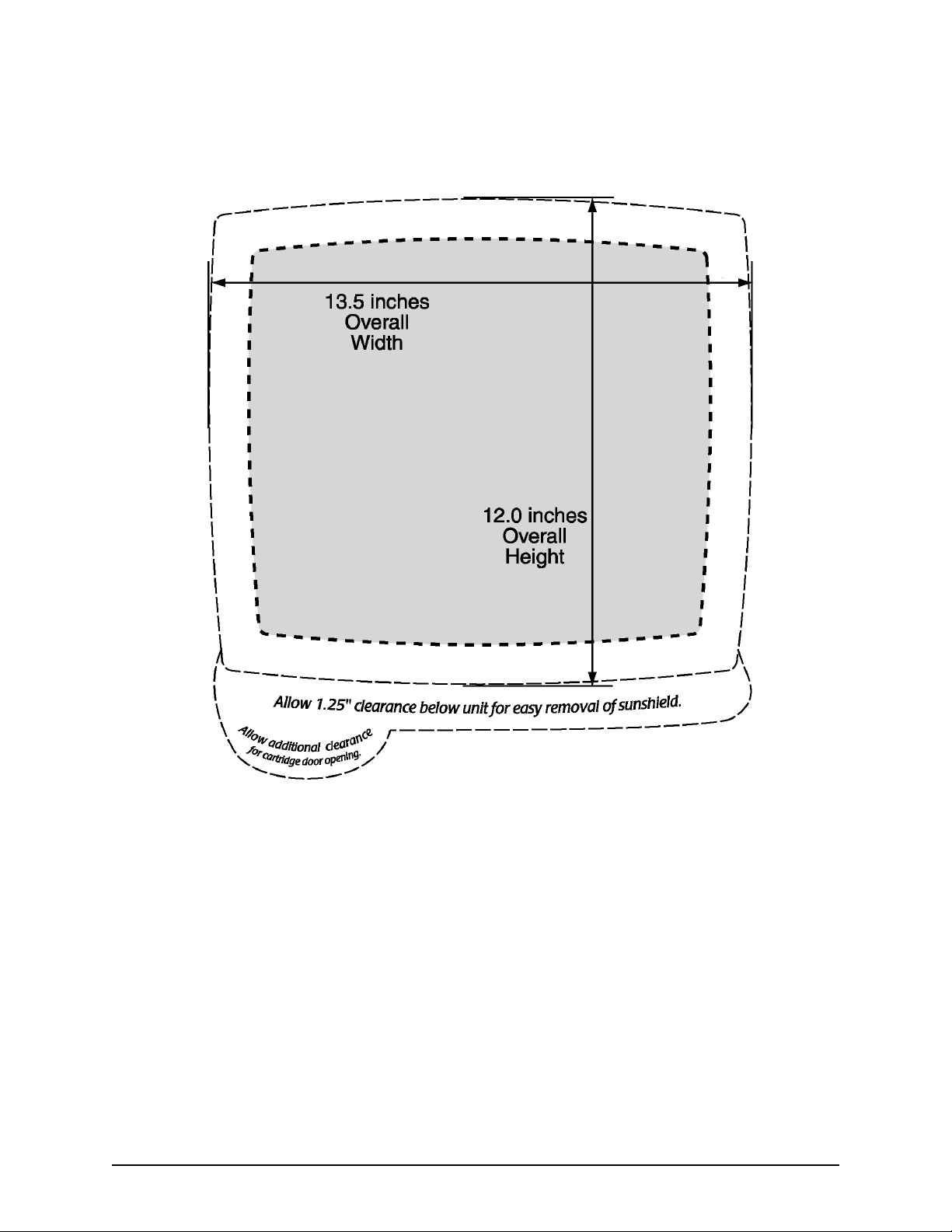
Figure 4 below shows the overall width and height
requirements for flush-mounting the 957. For further details,
see the full-size Northstar 957 Flush-Mounting Template (part
number GT957). This template should be used to drill the
mounting holes and cut the mounting panel in the exact
recommended locations.
CAUTION!
When flush mounting, be sure to mount the 957 on
a flat surface. Mounting on a curved surface can
break or distort the plastic and break the waterproof
seal.
Do not overtighten the mounting screws; you may
damage the case and compromise its waterproof
seal.
This type of physical damage will void the warranty.
Page 8 957 Installation Manual, Revision C1
Page 13
SECTION TWO: Installing and wiring the 957
Figure 2: 957 flush-mount clearance dimensions
957 Installation Manual, Revision C1 Page 9
Page 14

SECTION TWO: Installing and wiring the 957
Yoke-mounting the 957 Before drilling, turn the 957 to the desired angle on the yoke to
make sure there’s enough space for the cables. Leave clearance
space as follows:
•
at least 2 inches of space all around the sides and the top
•
at least 2.5 inches of space in the back for all of the cables
and connectors
•
at least 2.25 inches of space in the front for opening and
closing the chart cartridge door and inserting and
removing a chart cartridge
For an illustration of the recommended clearances, see Figure 3
and Figure 4 on the following pages.
Page 10 957 Installation Manual, Revision C1
Page 15

1.9”
SECTION TWO: Installing and wiring the 957
6.1”
2.3”
12.4”
2.5
8.2”
Figure 3: 957 yoke-mount dimensions (side)
957 Installation Manual, Revision C1 Page 11
Page 16

SECTION TWO: Installing and wiring the 957
”
13.5”
11.6”
12.4
Figure 4: 957 yoke-mount dimensions (front)
Page 12 957 Installation Manual, Revision C1
Page 17
Wiring the 957
SECTION TWO: Installing and wiring the 957
Avoiding cable wiring
shortcuts
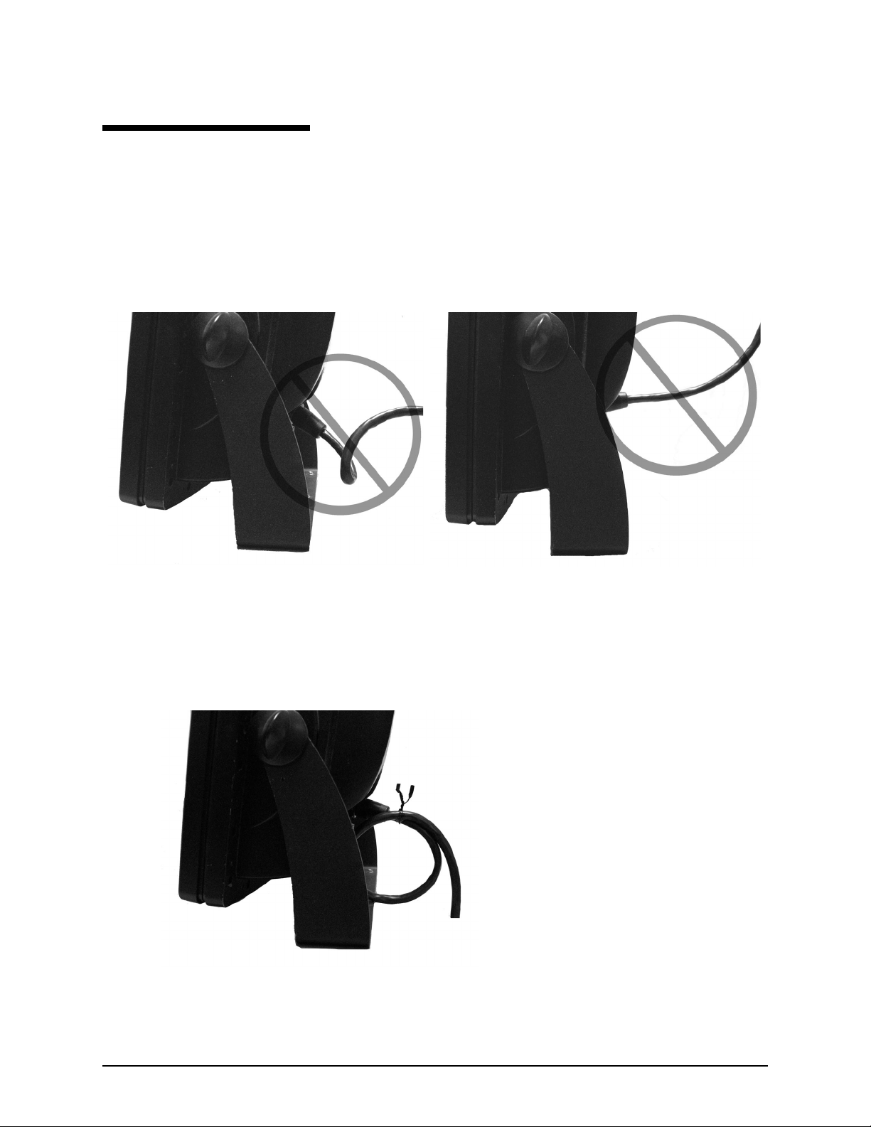
Most installation problems are caused by shortcuts taken with
system cables. When wiring the 957, follow the guidelines
illustrated in Figure 5 below.
DON’T DO THIS!
Do not make sharp bends in the
cables
Do not run cables in such a way that
might allow water to flow down into the
connectors
DO THIS!
•
Do make drip and service
loops
•
Do tie-wrap all cables to keep
them secure
•
If cables are shortened,
lengthened, or re-terminated,
do seal and protect all wiring
connections
•
Do leave room at the back to
service the 957
Figure 5: Avoiding cable wiring shortcuts
957 Installation Manual, Revision C1 Page 13
Page 18

SECTION TWO: Installing and wiring the 957
Understanding the
interface connectors
All of the 957’s interface connectors are shown in Figure 6:
”Interface connectors (back of 957),” below. The function of
these connectors is described in Table 1, below.
AUX connector
VGA connector
Power connector
GPS connector
NMEA connector VIDEO connector
Figure 6: Interface connectors (back of 957)
Table 1: Interface connector functions
Connector name Connector function(s) Connects to...
NMEA (NMEA I/O)
(18-pin port)
GPS (Antenna)
(7-pin RS232 port)
NMEA 1 input/output -------------->
NMEA 2 input/output -------------->
Honk alarm/200 ppnm ------------>
GPS/WAAS input/output --------->
Beacon input/output -------------->
NMEA devices: autopilots, etc.
same as NMEA 1
Remote honk alarm (or speed indicator)
2201 antenna
- or -
Northstar 2701 beacon receiver (optional)
Page 14 957 Installation Manual, Revision C1
Page 19
SECTION TWO: Installing and wiring the 957
Table 1: Interface connector functions (continued)
Connector name Connector function(s) Connects to...
AUX (Auxiliary)
(6-pin auxiliary NMEA
port)
PWR (Power) Power 10 to 36 VDC
VGA
(15-pin port)
VIDEO
(coaxial)
Electrical power
requirements
RS-422/NMEA input/output -----> Northstar 490 echo sounder (optional)
- or -
A second 957 (or to a Northstar 952/951/
941) for the waypoint-and-route transfer
function
Video output Remote display
Video input Any NTSC-compatible device
Power source
The 957 is a negative-ground system that’s reverse-polarity
protected. DC power is required from a 10-volt minimum to a
36-volt maximum using at least 16-gauge connecting wire.
CAUTION!
As a good safety practice, Northstar strongly
recommends that you connect the 957 to a circuit
breaker or 20-amp fuse at the power source
(battery).
Connecting the 957 to
ship’s power
A 10-foot power cable is shipped with the 957 system. You can
lengthen this cable to a maximum of 25 feet:
•
for a cable length up to 15 feet, the power connections
must use 16-gauge connecting wire or heavier
•
for a cable length from 15 to 25 feet, use 14-gauge
connecting wire or heavier
If you lengthen the power cable, use an external fuse at the
battery end as an added safety precaution. The fuse size
should match the size of the wiring on the vessel. See the
NMEA or the American Boating and Yachting Counsel
specifications to find the correct fuse to use with your cable.
For the best protection from noise, connect the power cable
directly to the battery or dedicated electronics buss. The green
ground wire should be connected to ship’s ground directly.
957 Installation Manual, Revision C1 Page 15
Page 20

SECTION TWO: Installing and wiring the 957
The power cable has an inline fuse to protect the vessel’s
wiring, prevent electrical fires, and prevent damage to the 957.
If you shorten this cable, be sure to keep the inline fuse intact.
The wires in the power cable must be connected as follows.
•
red → positive(+)
•
black → negative(–)
•
green → ship’s ground
NOTE:
Ground the 957 to the vessel to eliminate
interference. Without an earth grounding,
performance may be reduced. Secure the green
wire to the vessel’s nearest grounding point. If a
noise-free earth grounding point isn’t available, cap
and insulate the green wire—it shouldn’t be used
when an earth ground isn’t available, or with
systems using “floating” grounds.
Page 16 957 Installation Manual, Revision C1
Page 21

SECTION THREE: Installing and wiring the 2201
Introducing the 2201
The Northstar 2201 GPS pod is a self-contained, high
performance GPS antenna/receiver that also receives Wide Area
Augmentation System (WAAS) differential correction signals.
When connected to the 957, the 2201 provides the 957 with
WAAS-enhanced GPS position information.
For the 2201’s technical specifications, see Table 15, “2201
technical specifications,” on page 64.
CAUTION!
Do not open the 2201: There aren’t any serviceable
parts inside. Unauthorized tampering will
automatically void the warranty.
957 Installation Manual, Revision C1 Page 17
Page 22
SECTION THREE: Installing and wiring the 2201
Installing the 2201
NOTE:
Before permanently installing the 2201, try
temporarily installing it and using the 957 to see if
the 2201’s location works well.
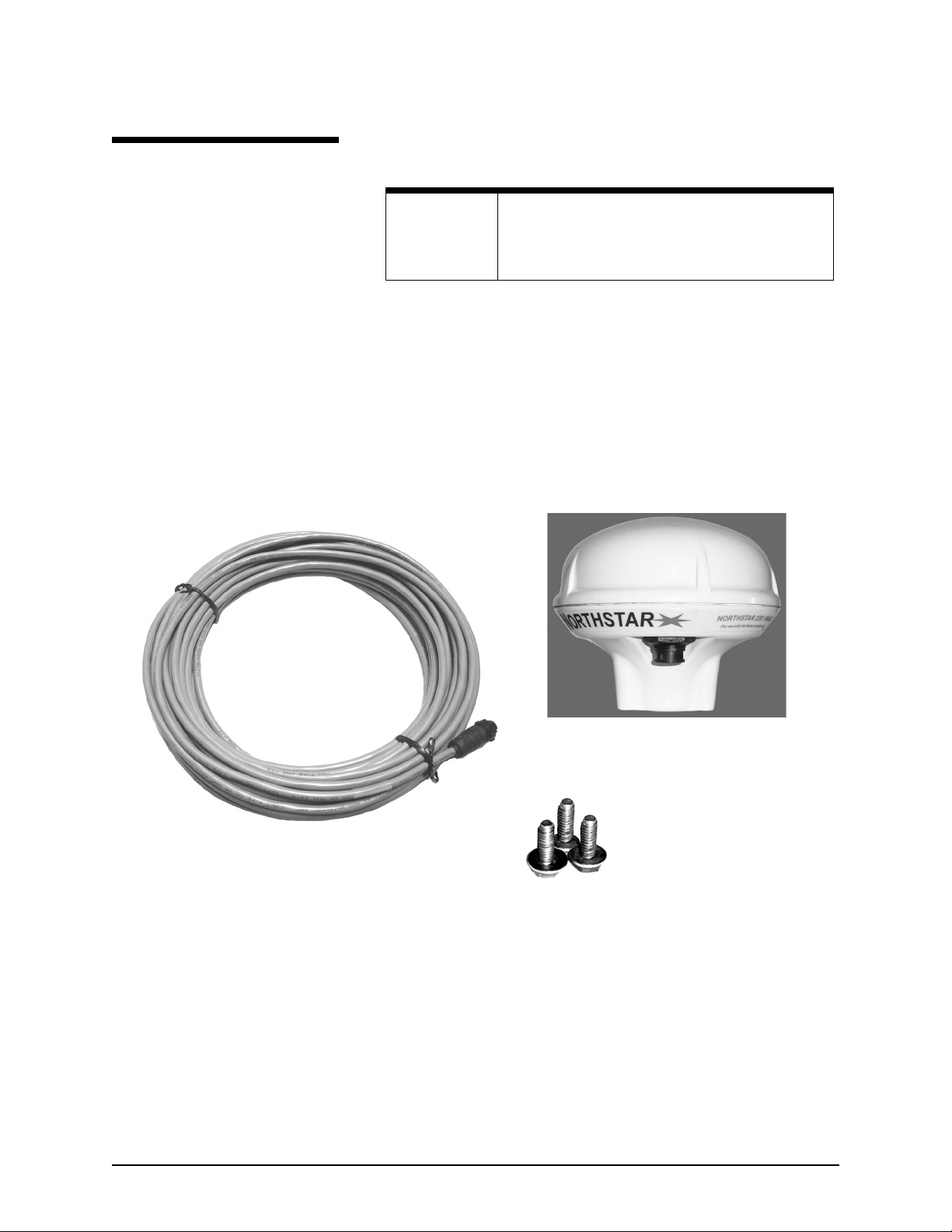
2201 parts list The 2201 includes the following parts (see Figure 7: ”2201
antenna components,” below):
•
2201 GPS/WAAS pod
•
3 mounting screws (10-32 UNF) and 3 washers for deck
mounting
•
50-foot 2201 cable (both ends have waterproof 7-pin
connectors)
2201 GPS/WAAS pod
3 mounting screws
50-foot 957POD-CA cable (with
and 3 washers
two finished connectors)
Figure 7: 2201 antenna components
Choosing the best
mounting location
Page 18 957 Installation Manual, Revision C1
Before you drill or cut, choose a mounting location that meets
the following criteria. The 2201 should be mounted:
•
where there’s enough mounting clearance to easily
connect the cable.
•
low on the vessel, since side-to-side motion caused by the
vessel’s rolling can degrade speed-over-ground (SOG) and
course-over-ground (COG) readings.
Page 23
SECTION THREE: Installing and wiring the 2201
•
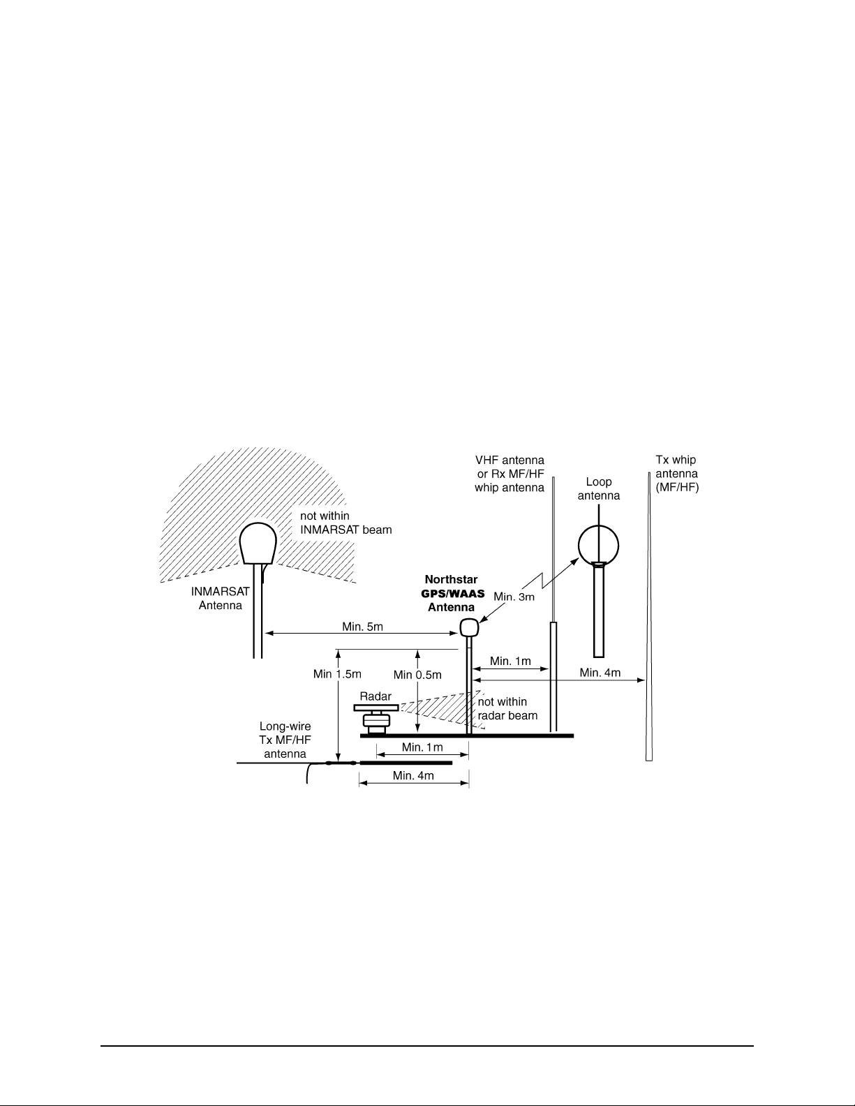
below the radiation plane of any INMARSAT or radar
antennas, and away from any other high-power
transmitting antennas (see Figure 8 on page 19).
•
high enough to provide an unblocked view of the sky in all
directions, and that minimizes or eliminates any objects
that block the 2201’s view of the sky (the 2201 uses
satellites down to zero degrees elevation or to the horizon).
•
away from masts or objects that could “shadow” the 2201,
but where there’s an adequate view of the sky.
To avoid mutual interference among different antennas on the
vessel, see the recommendations in Figure 8 below. This figure
shows the minimum distances that should separate GPS/WAAS
antennas from other antennas and physical mounting surfaces.
Normally, these guidelines produce a relatively trouble-free
installation. However, you may want to adjust these distances
to the particular equipment, since every installation is unique.
Figure 8: Recommended separation distances between antennas
Mounting the 2201 You can mount the 2201 in one of two ways:
•
onto a standard antenna mast
•
onto a flat surface
957 Installation Manual, Revision C1 Page 19
Page 24
SECTION THREE: Installing and wiring the 2201
Using a standard antenna mast
An optional magnetic
mount adapter (Northstar
part number AM110) is
available for certain
installations. To order, call
the Northstar Sales
Department.
❶
❷
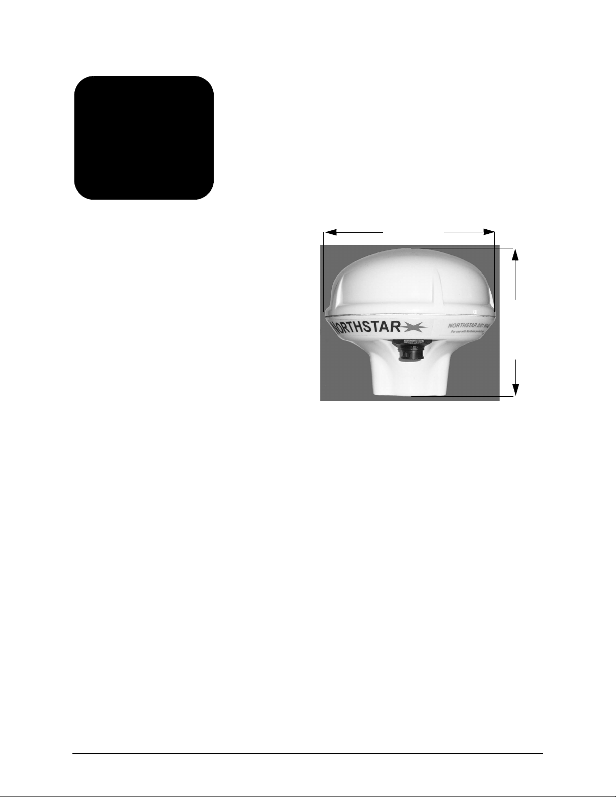
Using the 1”x 14 marine-industry standard UNS thread
mounting, install the base of the 2201 onto a standard
antenna mast. Do not overtighten or you may damage
the housing!
To avoid stressing the 2201’s connector with the weight of
the cable, use a tie-wrap or similar near the 2201 to hold
the cable’s weight.
4.50” (114mm)
3.79” (96mm)
Figure 9: Mounting position for a standard mast mount
Using a flat surface
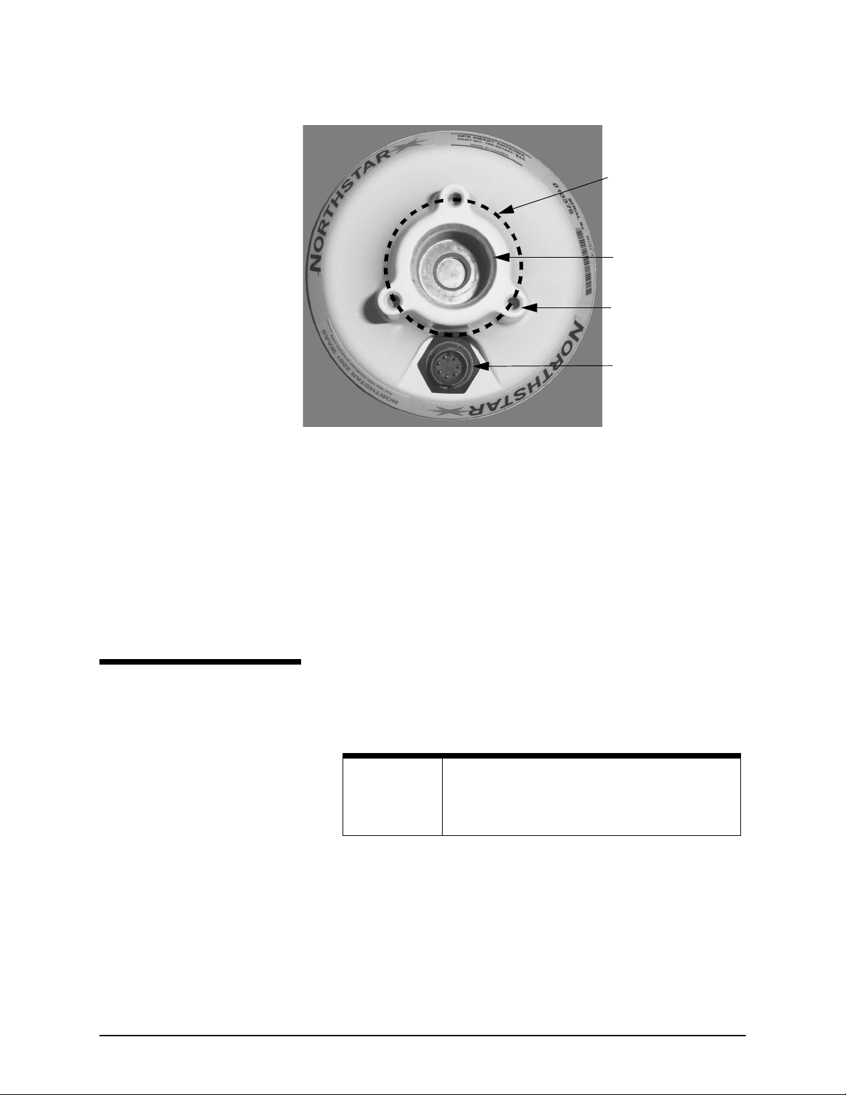
You can mount the 2201 onto a deck or any other flat surface:
❶
Using the three screws and washers provided, mount the
2201 onto the flat surface using three holes on a 1.75-inch
diameter circle (see Figure 10 below).
Page 20 957 Installation Manual, Revision C1
Page 25
SECTION THREE: Installing and wiring the 2201
φφφφ1.750
1.00 -14UNS-2Bx 1.00 deep.
3x 3/16” - 32UNF - 2B x .48
deep. Mounting holes
equally spaced around a
1.75” diameter circle.
Connector receptacle with 7
male contacts. Mating:
Switchcraft EN3C7FC or
equivalent.
Wiring the 2201
Connecting the 2201 to the
957
Figure 10: Mounting on a flat surface (viewed from below)
❷
Make sure the 2201 has enough mounting clearance so
that you can easily connect the cable. For example, mount
the 2201 on the edge of the deck, or drill a small hole in
the deck or other surface to allow the cable to pass
through.
NOTE:
You can shorten the 957POD-CA cable, but do not
lengthen it. The cable must be a maximum of 50
feet.
The 50-foot 957POD-CA cable connects the 957 with the 2201.
Both ends of the cable are finished with 7-pin connectors that
plug into the 2201 and 957:
1. Plug the 2201 end of the cable into the 2201, and the
957 end into the 957 connector labelled “GPS.” Note: The
cable’s connectors may look the same, but they are not
interchangeable.
957 Installation Manual, Revision C1 Page 21
Page 26
SECTION THREE: Installing and wiring the 2201
2. Coil any extra 2201-CA cable away from the 2201. Don’t
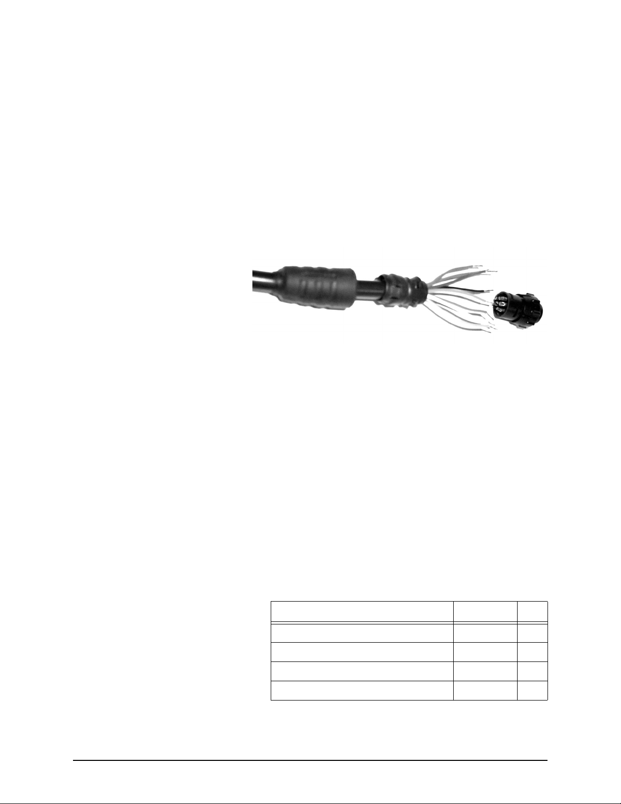
Re-fabricating the 957 connector (optional)
If you want to shorten the cable or remove its connector to
make more room to snake the cable, you can remove the
connector from the 957 end and then replace it:
pinch the cable or make any sharp bends, and don’t run
the cable where it interferes with any controls.
1. After shortening or snaking the cable, slide
the available heat shrink tubing onto the
cable, then slide the connector backshell
onto the cable, as shown below.
2. Prepare each wire for insertion into its solder
cup by stripping it and tinning it.
3. Carefully solder each wire to the appropriate
cup, as described in Table 2 below.
4. Slide the backshell down the cable and screw
it onto the connector body. It should be hand
tight.
5. Using the supplied screws, screw the strain
relief onto the backshell.
6. Slide the heat shrink tubing onto the connector. Be sure to leave room for the locking collar to retract.
7. Heat the shrink tubing until it shrinks around
the connector, providing a watertight seal.
For the pin numbers and functions for the 957 end of the cable,
see Table 2 below.
Table 2: Wiring connections for 2201 cable
Description Wire color Pin
RS232 RX1 (Main receive port) Blue 1
RS232 RX2 (Aux receive port) Orange 2
RS232 TX1 (Main transmit port) Green 3
Signal gnd Brown 4
Page 22 957 Installation Manual, Revision C1
Page 27
SECTION THREE: Installing and wiring the 2201
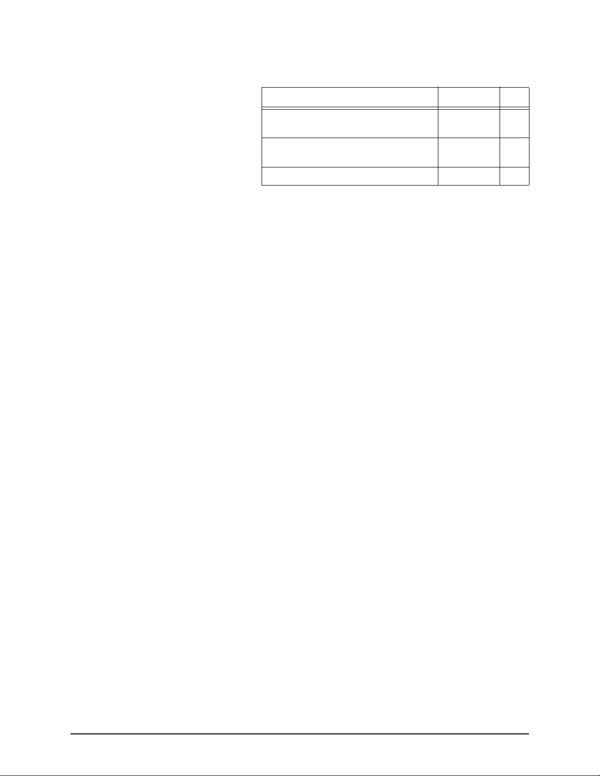
Table 2: Wiring connections for 2201 cable (cont.)
Description Wire color Pin
Selecting differential
options
Remote power-on
Ship’s power control
Power gnd
(system gnd)
Power in (9-36 VDC) Red 7
Black 5
White 6
The 957 has four settings for differential operations. For
instructions on choosing the correct setting, see ”Selecting
differential options” starting on page 36.
957 Installation Manual, Revision C1 Page 23
Page 28

SECTION THREE: Installing and wiring the 2201
Page 24 957 Installation Manual, Revision C1
Page 29
SECTION FOUR: Installing and wiring the 2701
Introducing the 2701
The Northstar 2701 is a high-performance, fully automatic
12-channel GPS/WAAS receiver and a two-channel beacon
receiver packaged into a self-contained enclosure. The 2701
receives differential corrections from ground-based
radiobeacons as well as from satellites transmitting WAAS
differential signals.
For the 2701’s technical specifications, see Table 16, “2701
technical specifications,” on page 65.
CAUTION!
Do not open the 2701: There aren’t any serviceable
parts inside. Unauthorized tampering will
automatically void the warranty.
957 Installation Manual, Revision C1 Page 25
Page 30

SECTION FOUR: Installing and wiring the 2701
Installing the 2701
2701 parts list
Choosing the 2701 mounting location
The 2701 includes the following parts:
•
2701 DGPS/WAAS receiver
•
10-foot data/power cable for connecting the 2701 to the
957 (both cable ends are finished)
•
AN205-P GPS/DGPS combination antenna
•
50-foot antenna cable for connecting the 2701 to the
AN205-P (both cable ends are finished)
The 2701 is housed in a rugged aluminum enclosure with a
mounting flange, gaskets, and watertight connectors. Though
designed to withstand the marine environment, the unit is not
completely waterproof. Protect the 2701 by installing it where
water won’t contact it directly or enter it by following data/
power or antenna cables.
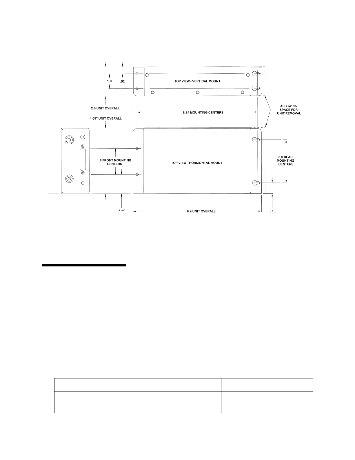
Mounting the 2701 You can mount the 2701 either horizontally or vertically using
the appropriate mounting holes—see Figure 11 on the next
page.
Keyhole slots at the rear will help if you’re installing the 2701
where access is limited and it’s hard to start the mounting
screws at the obstructed end. Securely tighten all mounting
screws to avoid vibration-related problems.
Page 26 957 Installation Manual, Revision C1
Page 31
SECTION FOUR: Installing and wiring the 2701
Figure 11: 2701 case and mounting dimensions
Wiring the 2701
Connecting the 2701 to the
957
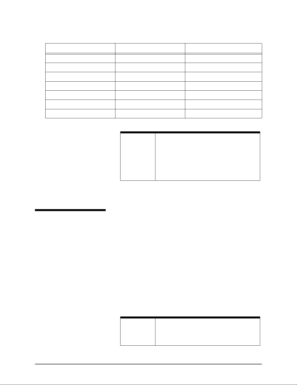
Table 3: Wiring connections for 2701 cable
957 connector (7-pin) 2701 connector (25-pin) Function
The 10-foot 957BDM-CA cable connects the 957 with the 2701.
Both ends of the cable are finished with connectors that plug
into the 2701 and 957. Plug the cable’s 25-pin connector into
the 2701, and the 7-pin connector into the 957 connector
labelled “GPS.”
In case you have to remove one of the cable’s connectors, be
sure to re-fabricate the cable using the wiring connections
described in the table below.
17GPS RX1 (Blue)
2 21 BDM RX1 (Orange)
957 Installation Manual, Revision C1 Page 27
Page 32
SECTION FOUR: Installing and wiring the 2701
Table 3: Wiring connections for 2701 cable (cont.)
957 connector (7-pin) 2701 connector (25-pin) Function
36GPS TX1 (Green)
4 20 BDM TX1 (Brown)
5 12 Power CTL (Black or Gray)
6 13 GND (White)
7 25 Power + (Red)
6 NC Drain Wire
NC KS131 Foil Shield
Installing the AN205-P antenna
Choosing the antenna’s
mounting location
NOTE:
The 2701 operates with Northstar’s AN205-P “combo” GPS/
DGPS antenna. Mount the antenna high enough to clear any
objects and get an unobstructed view of the horizon in all
directions. Mount it low enough on the vessel to avoid extra
motion from pitching and rolling, and lower than any
high-power transmitting antennas, such as radar or satcom (see
Figure 8 on page 19 for recommended separation distances
between antennas). Keep the antenna at least six feet away
from objects that can “shade” GPS or differential signals.
Double-check all wiring if you re-fabricate the
cable. A small, but significant, number of 2701’s are
damaged due to incorrectly wired connections.
Such damage is not covered under warranty. Be
sure you aren’t applying primary voltage directly to
any of the 2701’s signal input/output wires. This
may vaporize the internal circuit board conductors.
NOTE:
Page 28 957 Installation Manual, Revision C1
Before permanently installing the AN205-P, try
temporarily installing it and using the 957 to see if
the antenna location works well.
Page 33
SECTION FOUR: Installing and wiring the 2701
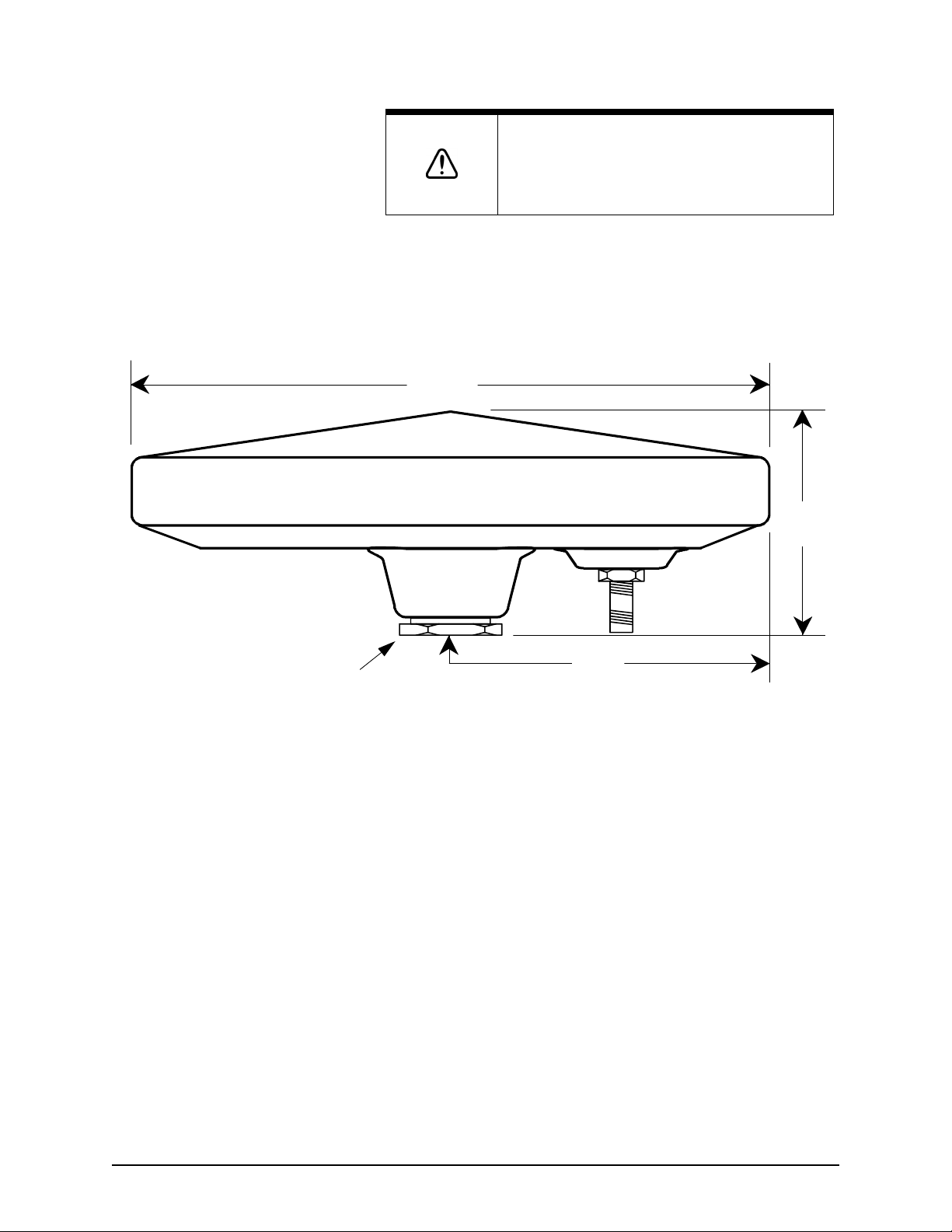
Use the locking nut shown to prevent
rotation of the antenna or bottoming
out of the mounting stanchion into the
threaded mount portion of the antenna.
If done with enough force, either of
these may break the antenna.
CAUTION!
If position data is intermittent, make sure you have the proper
cable length, and verify the quality of the antenna location and
the quality and proper termination of the connectors. Also,
make sure that the 2701’s ground lug terminal is securely
connected with a heavy gauge conductor to ship’s ground.
Don’t mount the antenna near rotating warning
beacons or strobe lights, electric motors,
fluorescent lights, or other RF sources. These can
create RF interference to the differential reception.
7.00
2.5
TNC
3.5
Connecting the 2701 to the
antenna
Figure 12: Northstar AN205-P antenna dimensions
The 50-foot antenna cable connects the 2701 with the
AN205-P antenna. The cable length must be a maximum of 50
feet but can be shortened to the desired length.
Note: Installations that require a cable length from 50 to 100
feet should order the AN206 combo antenna and a 100-foot
length of coaxial cable from the Northstar Sales Department.
Don’t make any tight bends in the cable, and fasten it along its
length to avoid chafing or whipping or any kind. Coil up any
unused length of cable. Be sure that the cable connectors are
securely fastened.
957 Installation Manual, Revision C1 Page 29
Page 34

SECTION FOUR: Installing and wiring the 2701
Page 30 957 Installation Manual, Revision C1
Page 35
SECTION FIVE: Checking out the system
Inserting a chart cartridge
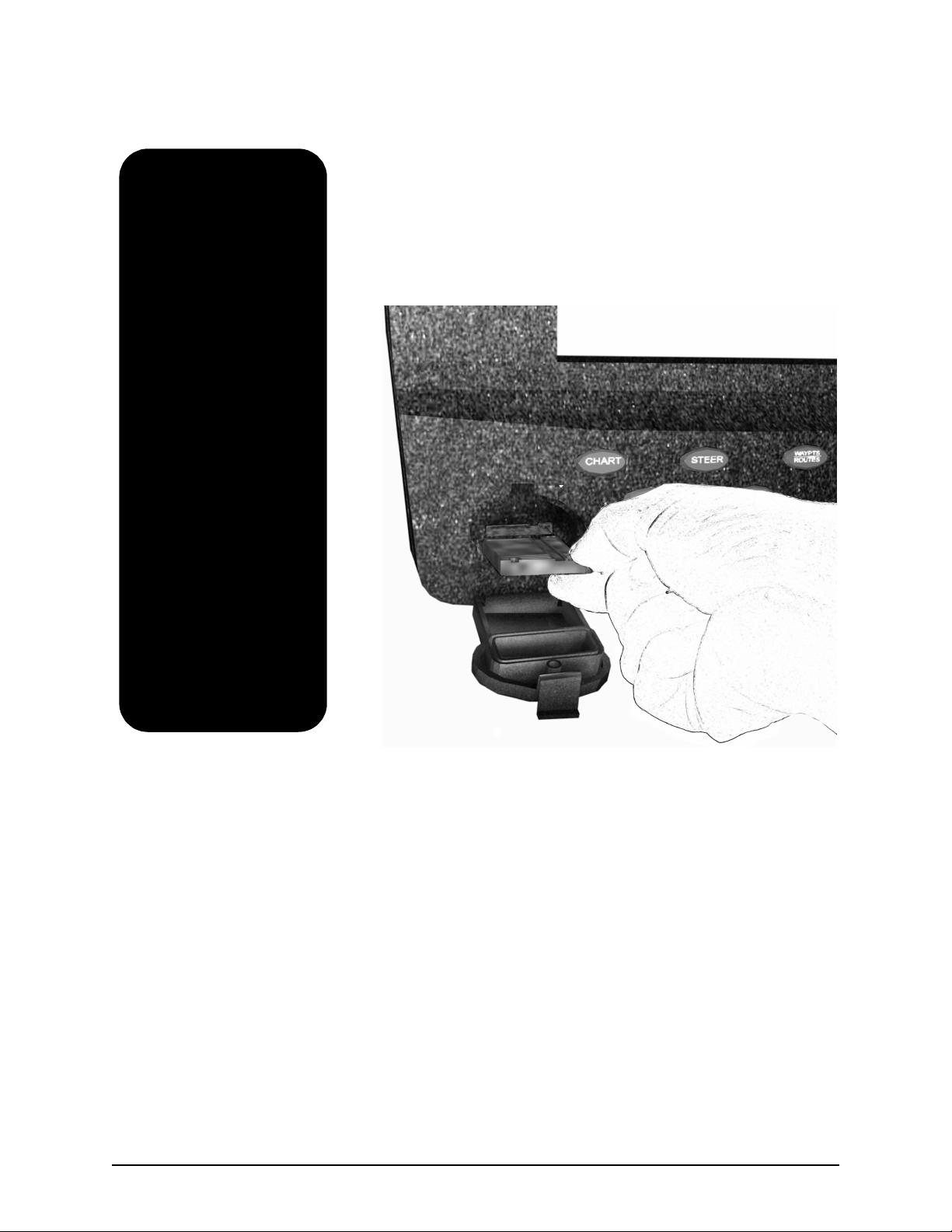
The cartridge slot is located at the lower left-hand corner of the
957. Before inserting a Navionics chart cartridge, make sure its
label is facing up and that the cartridge is oriented as shown in
Figure 13 below. Insert the cartridge gently but firmly into
position with one straight, smooth motion. If you only partially
insert the cartridge, stop, then move the cartridge again, it may
get stuck in an awkward position.
957 INSTALLATION MANUAL, Revision C1 Page 31
Page 36
SECTION FIVE: Checking out the system
The Navionics chart
cartridge must stay free
from debris and
moisture at all times. To
ensure that you don’t
expose the cartridge to
any environmental
damage, please use
caution when changing
the cartridge. Be careful
when inserting the
cartridge into the 957
(see description above
and illustration at right).
When you’re not using
the cartridge, store it in
a clean, dry place away
from heat, humidity,
and dust. Improper
handling and storage of
the cartridge may
damage the 957. Such
damage isn’t covered
under the 957 warranty.
Figure 13: Properly inserting a chart cartridge
Page 32 957 INSTALLATION MANUAL, Revision C1
Page 37
SECTION FIVE: Checking out the system
Turning the 957 on and off
To turn on the 957, briefly press the PWR key. The 957 emits
several short beeps as it displays the START-UP screen, then the
957 performs a series of self-tests to check its critical
components and functions.
Next, a message is shown as a reminder against relying on the
957’s chart cartography as the only means of safe navigation.
To continue, accept the warning message by pressing any one
of the five function keys (CHART, STAR, STEER, NAV LOG, or
WAYPTS/ROUTES) located below the display screen.
NOTE:
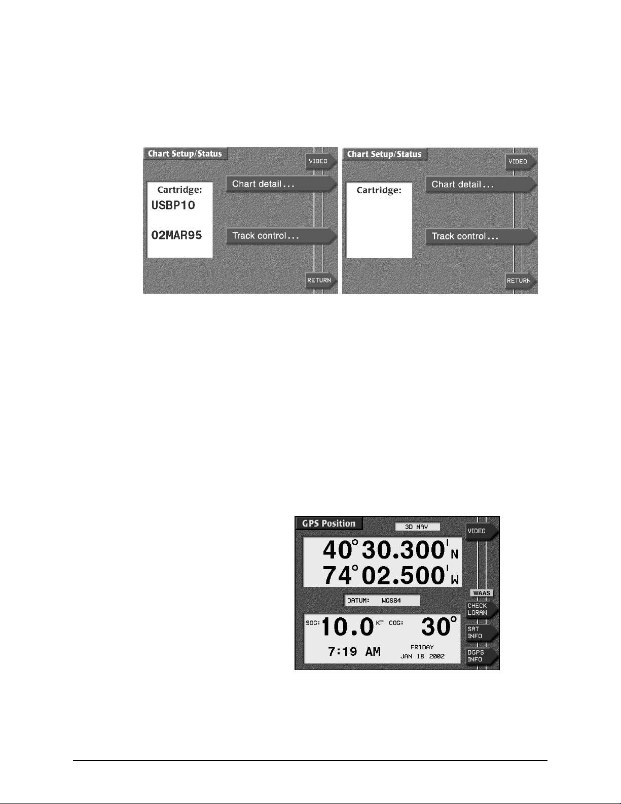
To identify the cartridge inside the 957, press the CHART
SETUP menu key to the right of the CHART screen to display
the CHART STATUS screen (the cartridge door must be fully
closed and latched to display this information):
957 INSTALLATION MANUAL, Revision C1 Page 33
A brief warm-up period may be required for the
display screen to reach its full intensity.
Page 38
SECTION FIVE: Checking out the system
•
if a cartridge is inside, the cartridge name and date are
shown on the left of the CHART SETUP/STATUS screen
(screen at left, below).
•
if a cartridge isn’t installed or is installed incorrectly, the
words NONE INSERTED are shown (screen at right, below).
NONE
INSERTED
The cartridge name comes from its Navionics catalog number.
Not all cartridges will have a date, especially older ones; in this
case, only the word PRESENT is shown rather than the name
and date.
Checking satellite status
The 957 uses a high-performance GPS receiver as its primary
source of position data, augmented by either the WAAS
satellite system, or the radiobeacon differential (DGPS) system
if the 957 is connected to the optional Northstar 2701 receiver.
To see if the 957 is using WAAS or DGPS, press the CHART key
to display the GPS POSITION screen and look for the WAAS or
DGPS indicator below and to the right of the lat/lon display.
.
Page 34 957 INSTALLATION MANUAL, Revision C1
Page 39
SECTION FIVE: Checking out the system
To see more information about DGPS, on the GPS POSITION
screen, press the DGPS INFO key to display the DGPS STATUS
screen. Check for low noise levels and mid-range SNR readings.
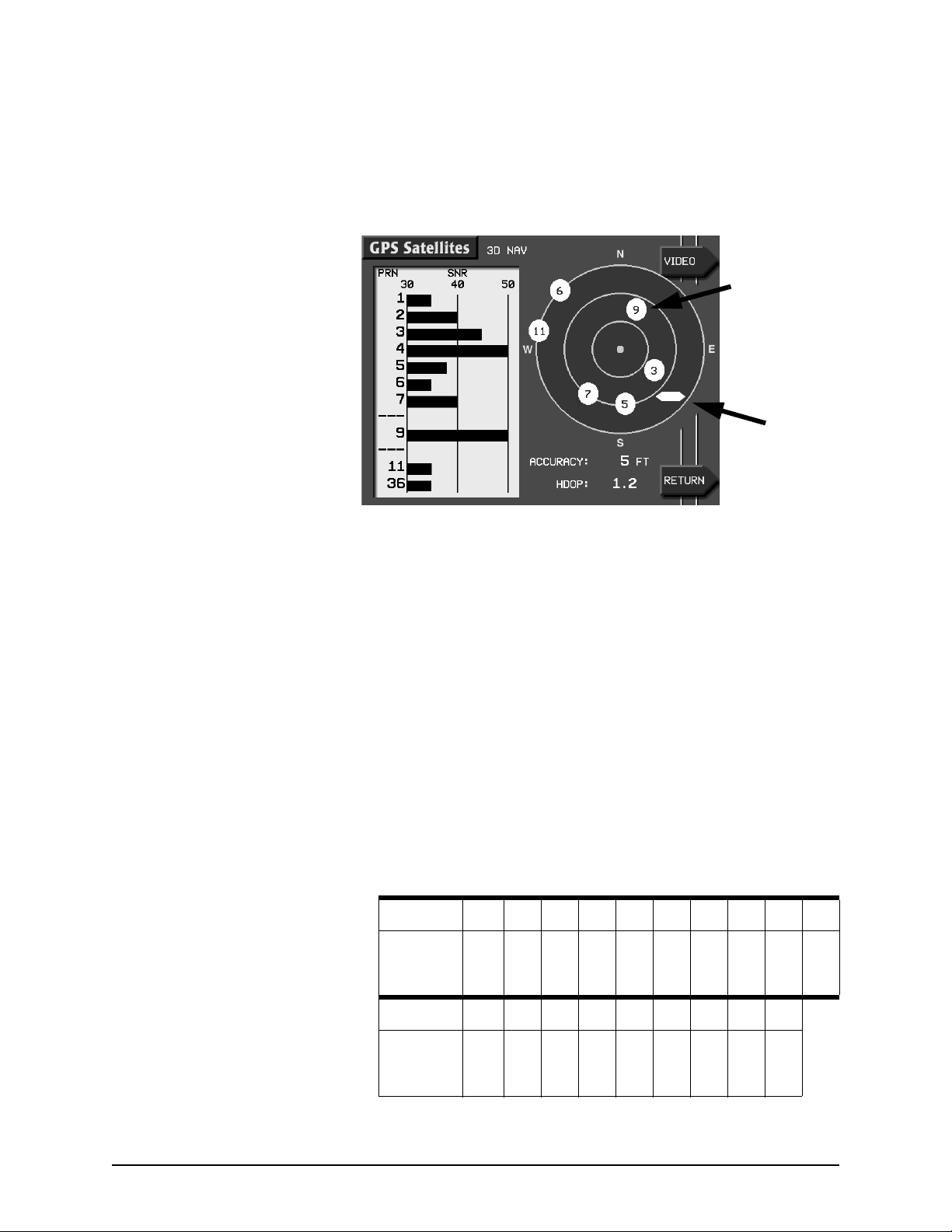
To display more information about signals received from the
satellites, press the SAT INFO menu key.
GPS
satellite
number
36
WAAS
satellite
number
Figure 14: Satellites on the GPS satellites screen
The satellite map on the GPS SATELLITES screen shows the
current location of the satellites in the sky. The 957 displays
GPS satellites as circles; WAAS satellites as hexagons. You can
check the quality of their signals by looking at each satellite’s
Signal-to-Noise Ratio (SNR). The higher the ratio, the better the
quality.
While the U.S. government identifies WAAS satellites by their
pseudo random number (PRN)—a three-digit number ranging
from 120 to 138—the 957 identifies them by two-digit numbers
ranging from 33 to 51. For example, the satellite for the Atlantic
Operating Region (AOR) is PRN 122, which the 957 displays as
35. See Table 4 below for the satellite identification numbers
that may be displayed on the 957’s screen.
Table 4: Satellite identification numbers
PRN
ON GPS
SATS
SCREEN
120 121 122 123 124 125 126 127 128 129
33 34 35 36 37 38 39 40 41 42
PRN
ON GPS
SATS
SCREEN
957 INSTALLATION MANUAL, Revision C1 Page 35
130 131 132 133 134 135 136 137 138
43 44 45 46 47 48 49 50 51
Page 40

SECTION FIVE: Checking out the system
Selecting differential
options
About auto-dimming
mode
The 957 has several settings for differential reception. To select
one, press the STAR key to display the OPTIONS/SERVICE INFO
screen, then press the RECEIVER OPTIONS key to display the
RECEIVER OPTIONS screen. The DIFFERENTIAL OPERATIONS
field offers the following options (depending on the equipment
that’s connected to the 957):
• DISABLED - to turn off all differential corrections
• RADIO BEACON - to force radiobeacon differential if the
957 is connected to a radiobeacon source (for example, the
optional 2701)
• WAAS - to force WAAS differential corrections if the 957 is
connected to a WAAS-capable unit (for example, the 2201
or optional 2701)
• AUTO - (the default setting) to prefer WAAS differential
corrections, but if the 957 is connected to the optional
2701, the 957 will automatically switch to radiobeacon
corrections if and when WAAS becomes unavailable or is
less accurate than radiobeacon
When the display screen is at full brightness, if the 957 gets too
hot inside due to the outside temperature and sunlight, the
display screen will automatically dim. Auto-dimming helps
maintain the integrity of the display and reduce power
consumption when the 957 is on and running too hot for its
current environment. You can override the auto-dim function
at any time by increasing the brightness with the BRIGHTNESS
key. The 957 may dim again as required so as not to exceed the
maximum internal temperature.
Using the remote control If you point the remote directly at the 957 and are within nine
feet, you can operate all of the 957’s keys except the PWR key.
Turning off the 957
Page 36 957 INSTALLATION MANUAL, Revision C1
To turn off the 957, press and hold the PWR key for a few
seconds until the screen goes dark.
Page 41

SECTION FIVE: Checking out the system
Installation-test checklist
To check-out the 957 system after installation:
1. Turn on the 957, then check for the presence of GPS,
WAAS, or DGPS signals.
2. Review the functions: With a chart cartridge inserted,
check that the CHART screen is displayed.
3. Confirm that the DIFFERENTIAL OPERATIONS option is at
the desired setting. If not, press the STAR key to display
the OPTIONS/SERVICE INFO screen, then press the
RECEIVER OPTIONS menu key to display the RECEIVER
OPTIONS screen. Press the EDIT key, change it to the
desired setting, then press the ENTER key.
For more in-depth information about troubleshooting the 957
installation, see ”SECTION SEVEN: Troubleshooting and
servicing the 957 system” starting on page 55.
957 INSTALLATION MANUAL, Revision C1 Page 37
Page 42

SECTION FIVE: Checking out the system
Page 38 957 INSTALLATION MANUAL, Revision C1
Page 43
SECTION SIX: Interfacing the 957 system
Wiring the connector pins
The 957 has the following interface ports:
•
NMEA 1 and 2 input and output (on the 18-pin NMEA
connector)
•
7-pin GPS connector
•
RS-232 input and output (on the 18-pin NMEA connector)
•
RS-422 / NMEA input and output (on the 6-pin AUX
connector)
•
Composite video input (on the VIDEO connector)
•
VGA output (on the VGA connector)
You can display the list of wires for the connectors: Press the
STAR key to display the OPTIONS/SERVICE INFO screen, then
press the PORT SETUP OPTIONS menu key to display the
PORT SETUP OPTIONS screen, then press the WIRING INFO
menu key.
957 INSTALLATION MANUAL, Revision C1 Page 39
Page 44

SECTION SIX: Interfacing the 957 system
Table 5: NMEA connector pins
Description Wire color Pin
NMEA port 1 input A brown 3
NMEA port 1 input B blue 1
NMEA port 1 input ground white with blue stripe 4
NMEA port 1 output A violet 12
NMEA port 1 output B gray 7
NMEA port 1 output ground blue with white stripe 8
NMEA port 2 input A white with brown stripe 6
NMEA port 2 input B brown with white stripe 2
NMEA port 2 input ground white 5
NMEA port 2 output A yellow 15
NMEA port 2 output B orange 11
NMEA port 2 output ground black 10
RS-232 ground tan 17
RS-232 RX green 16
RS-232 TX red 18
External ground/foil drain white with orange shield 9
Reserved orange with white stripe 13
Honk out/200 PPNM (pulses
per nautical mile)
pink 14
Figure 15: NMEA connector pin configuration
Page 40 957 INSTALLATION MANUAL, Revision C1
Page 45
SECTION SIX: Interfacing the 957 system
Table 6: Aux connector pins
Description Wire color Pin
Shield/Gnd brown 1*
Remote On Gnd green 1*
Remote On white 2
NMEA AUX In (B) black 3
NMEA AUX Out (B) orange 4
NMEA AUX Out (A) violet 5
NMEA AUX In (A) blue 6
* Pin 1 on the AUX port requires two connections from the
cable.
The red wire is not connected on the 957 end, and should be
insulated and capped.
For the aux port pin configuration, see Figure 17 on page 51.
Configuring the NMEA output ports
You can set each output port to meet the requirements of
devices that conform to the NMEA 0183 or other data-format
specifications:
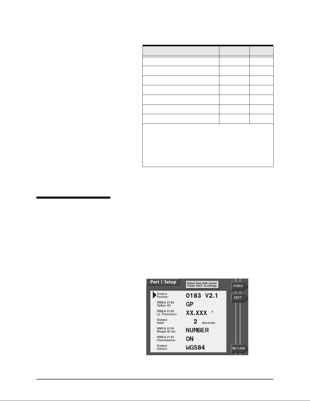
1. Press the STAR key until you see the OPTIONS/SERVICE
INFO screen, then press the PORT SETUP OPTIONS
menu key to display the PORT SETUP OPTIONS screen.
2. Press the PORT 1 SETUP or PORT 2 SETUP menu key to
display a list of seven data-format control options, as
shown below.
957 INSTALLATION MANUAL, Revision C1 Page 41
Page 46
SECTION SIX: Interfacing the 957 system
The devices you’re interfacing with the 957 may have special
requirements, so check their installation instructions. The
Northstar factory settings are fine for most peripheral devices,
but the following options, as described below, are available if
needed.
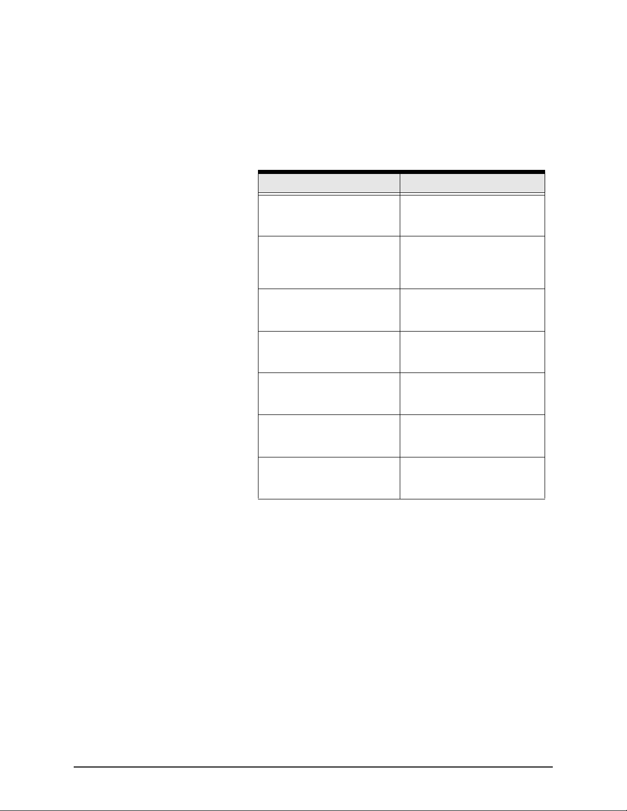
Table 7: Setup options for the NMEA port
Setting Choices
OUTPUT FORMAT
(see below)
NMEA 0183 TALKER ID
(see page 44)
NMEA 0183 LL PRECISION
(see page 44)
OUTPUT RATE
(see page 45)
NMEA 0183 WAYPT ID AS
(see page 45)
NMEA 0183 CHECKSUMS
(see page 46)
OUTPUT DATUM
(see page 46)
choose 0183 V2.1, 0180,
NONE, 0183 RAY, or DATAM
CDX
choose GP, LC, or II, to make
the 957 look like a GPS receiver,
Loran-C receiver, or an
“integrated instrument”
choose hundredths of minutes,
thousandths of minutes, or
ten-thousandths of minutes
choose 2 to 999 seconds for the
interval at which data is sent to
the external device
choose NAME or NUMBER for
the identifier of waypoints sent to
the external device
choose ON or OFF for
compatibility with some older
devices
choose from a list of datums to
apply to your lat/lon coordinates,
if necessary
Choosing the output
format
The 957 outputs navigation data in any of several standard
formats as required by the receiving, or “listener,” device. The
OUTPUT FORMAT option provides the following choices:
• NMEA 0183 Version 2.1 is a general-use interface output
format used by most autopilots, radars, plotters, and other
equipment. (NMEA 0183 Version 1.5 sentences—BWC, GLL,
and RNN—allow backwards compatibility with marine
equipment designed for this earlier version of 0183).
• NMEA 0180 is an infrequently used format, developed in
the late 1970’s, required by certain older autopilots.
•
None turns the outputs off for when the 957 isn’t
connected to an external device.
•
0183 Ray is used when transmitting/receiving position
information to or from Raytheon equipment. In Raytheon’s
Page 42 957 INSTALLATION MANUAL, Revision C1
Page 47
SECTION SIX: Interfacing the 957 system
NMEA 0183 format, the checksum isn’t used. (Note: Since
the checksum isn’t used, the 957 may receive incorrect
NMEA data when connected to an external Raytheon
loran.)
•
Datamarine CDX is required by Datamarine’s
cross-track-error indicators, the latest of which display
distance and bearing to the waypoint.
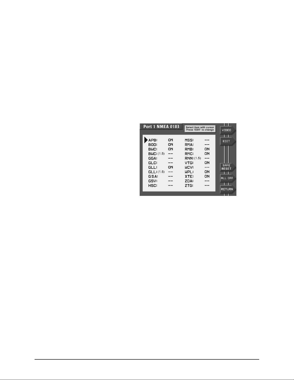
Displaying NMEA output sentences
When you select 0183 or 0183 RAY as the output format (after
pressing the EDIT menu key) and press ENTER, a screen is
displayed showing all the NMEA 0183 sentences the 957 can
output.
Three-letter abbreviations identify each sentence and are listed
alphabetically. (For the meaning of these sentences, see the
NMEA interface specifications document published by the
NMEA.) The sentences to be output are followed by the word
ON; those that won’t be output have two dashes indicating that
they’re off. Some devices can’t handle all these sentences
correctly, so you can customize the output here by turning
individual sentences on or off. In general, you may want to turn
on only those sentences used by the particular equipment
interfaced to the 957.
Turning NMEA output sentences on and off
To turn on or off the 957’s NMEA 0183 sentences, first follow
the above description to display the 0183 SENTENCE screen,
then follow these steps:
1. Press the CURSOR PAD to highlight the sentence you
want to turn on or off, then press the EDIT menu key.
2. Press the CURSOR PAD to toggle the sentence on or off,
and press ENTER to make your selection (or CLEAR to
leave it unchanged).
957 INSTALLATION MANUAL, Revision C1 Page 43
Page 48
SECTION SIX: Interfacing the 957 system
3. Repeat for each sentence as desired. When you’re done,
press the RETURN menu key to go back to the PORT
SETUP screen.
NOTE:
If you want to set all the sentences to the factory settings for
recommended output, press the SAFE RESET menu key.
If you want to turn on only a select few sentences for output,
press the ALL OFF menu key to turn off all sentences, then
turn the desired ones back on.
The NMEA ON/OFF item list controls only the
Version 2.01 GLL and BWC items, not the 1.5
version of these items. Thus, ON/OFF changes
made to the Version 1.5 GLL and BWC output
items have no effect on the data actually output
unless you select that particular format version.
Choosing the talker ID The NMEA 0183 standard requires that the equipment you’re
interfaced to—the “listener”—knows what type of device is
transmitting the data. The 957’s talker ID tells the listener that
it is receiving information from a navigation source, not a
communications or sensor device—which transmits completely
different forms of data. Certain listening devices will only
accept navigation data identified as coming from loran (LC),
GPS (GP), or an integrated instrument (II). The 957 lets you set
its talker ID to LC, GP, or II to match what the listener device is
expecting:
1. Check the listener device’s instruction manual to
determine which “talker ID” codes it will respond to.
2. At the PORT 1 SETUP or PORT 2 SETUP screen, press the
CURSOR PAD to highlight the NMEA 0183 TALKER ID
option, then press the EDIT menu key.
3. Scroll through the three choices using the CURSOR PAD
to make your selection, and press the ENTER key. The
interfaced equipment will now receive the 0183 data in
the correct nav-source format.
Choosing the lat/lon
precision
Page 44 957 INSTALLATION MANUAL, Revision C1
For more flexibility when communicating with a variety of
other devices, you can set the precision level of the 0183
position information output by the 957. The choice you make
depends on the equipment to which you’re outputting the
NMEA data (for the number of digits of precision required for
that particular device, see the manufacturer’s instructions). You
have three choices:
Page 49
SECTION SIX: Interfacing the 957 system
• XX.XX ’ (lat/lon precision to two decimal places/
hundredths of minutes/or 60 feet)
• XX.XXX ’ (lat/lon precision to three decimal places/
thousandths of minutes/or 6 feet; this is the factory
setting)
• XX.XXXX ’ (lat/lon precision to four decimal places/
ten-thousands of minutes/or roughly ½ foot)
The 957 conforms to the NMEA version 2.00 standard, and is
also compatible with version 1.50. Electronic and pen plotting
devices typically benefit the most from three and four decimal
places of precision. However, many older devices (and some
current autopilots) designed to operate with the original 0183
and other formats can only function with two-place precision.
NOTE:
Position information can be output and displayed to
four decimal places, but the ability to actually
navigate with such accuracy is limited by the
accuracy of the Loran and GPS systems.
Therefore, choosing more decimal places doesn’t
necessarily increase navigating accuracy.
Choosing the output rate The default rate for standard NMEA 0183 output is two
seconds. The 957 lets you use a one-second update interval, a
rate of 1 Hz, under limited circumstances, for NMEA and
diagnostic data output. Using the 1-Hz output option requires
some thought when specifying either NMEA 0183 (NMEA
version 2.0) or Raytheon (RAY 0183). Because there isn’t
enough time to transmit all available sentences within one
second, you must select for output only those that are needed.
If you select more sentences than can be output in one second,
the 957 displays the following error message:
SORRY, CAN’T DO THAT. TOO MANY SENTENCES FOR 1 SEC
INTERVAL
In this case, you must select fewer sentences.
There are some applications that need a longer update period.
In that case, you can increase the span to 999 seconds.
Choosing the waypoint
identification (ID)
Many marine devices can display waypoint names if they’re
output by the 957. At the PORT 1 SETUP or PORT 2 SETUP
screen, highlight the NMEA 0183 WAYPT ID AS option, then
press the EDIT menu key. Change the option from NUMBER to
NAME, and press the ENTER key when done. If capable, the
listening device will now display six-character waypoint names.
957 INSTALLATION MANUAL, Revision C1 Page 45
Page 50

SECTION SIX: Interfacing the 957 system
Choosing the checksum
setting
NOTE:
Some older devices may not accept sentences containing the
NMEA 0183 checksum that’s output by the 957. In such cases,
the device may not work properly or at all. If you have
problems interfacing to older equipment, the 957 offers the
flexibility to turn off the NMEA 0183 checksum:
1. At the PORT 1 SETUP or PORT 2 SETUP screen, press the
CURSOR PAD to highlight the NMEA 0183 CHECKSUMS
option, then press the EDIT menu key.
2. Press the CURSOR PAD to change the setting from ON to
OFF, and press the ENTER key when done.
Be sure to see if the listening device can do this
before you change the
option. Many older devices won’t understand this
identifier, and using it may cause problems with
displaying waypoint information or when following
routes.
There is no standard for identifying how numbers
should be assigned when converting waypoints
from names to numbers. When you export
waypoint information as numbers to a peripheral
device, be aware that numbers aren’t sequentially
defined and may be re-used on a random basis.
NMEA WAYPT ID AS
Selecting an independent NMEA output-port datum
Using 200 ppnm output
You can adjust the geodetic datum for NMEA 0183 ports 1 and
2, separately from the datum you choose for position display. At
the PORT SETUP 1 or PORT SETUP 2 screen, highlight the
OUTPUT DATUM option, then press the EDIT menu key. Scroll
through the choices to make your selection. To apply this
chosen datum to the lat/lon coordinates in the NMEA 0183
output sentences, press the ENTER key.
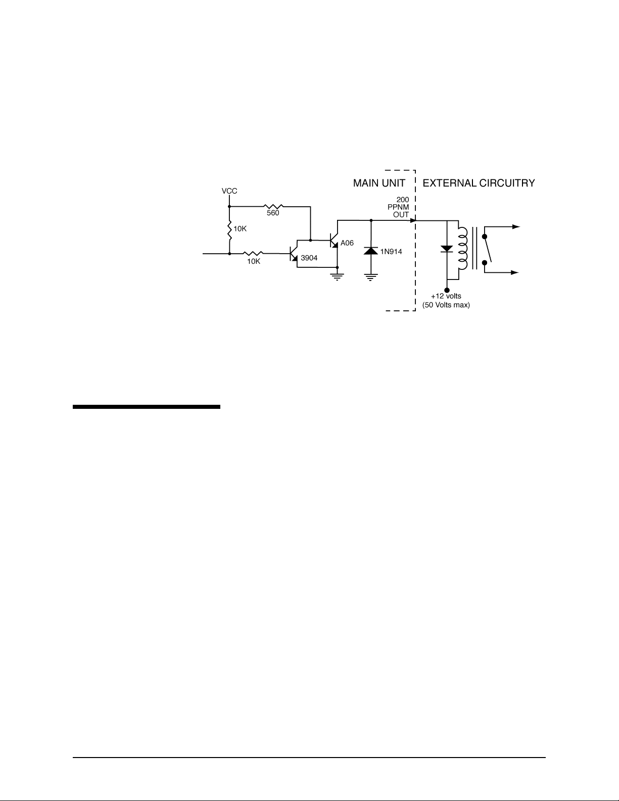
The 957 provides an open-collector transistor output (on pin
14) that’s programmed to produce 200 pulses per nautical mile.
The emitter of the NPN transistor is connected to ground, and
its collector connects to the output pin (see Figure 16: ”Wiring
for 200 PPNM output,” below). The output can sink 100mA,
and can withstand a maximum positive voltage of 50 volts.If
the output connects to an inductive device (for example, a
Page 46 957 INSTALLATION MANUAL, Revision C1
Page 51
SECTION SIX: Interfacing the 957 system
relay), a spike suppression diode such as a 1N4001 should be
connected across the load. Cathode connects to the power side
of the device and anode connects to the output pin side. The
output is normally open, switching to ground for 80ms. It
supports speeds from zero to 100 knots (clamps at 100kt).
Configuring the RS-232 port
Using SC-104 in
Figure 16: Wiring for 200 PPNM output
The RS-232 port on the NMEA connector is used to interface to
any of the following equipment:
•
any compatible SC104 output
•
a PC for downloading your waypoints, or for uploading
957 software updates
The following sections describe the RS-232 port’s settings for
SC-104 in, and copy port 1 and 2.
THE SC-104 IN setting lets the 957 accept optional differential
corrections from any source that transmits the standard SC-104
data stream. When using SC-104 IN, be sure that the BAUD
RATE setting also matches the beacon receiver’s baud rate
requirements.
Using copy port 1 and copy
port 2
957 INSTALLATION MANUAL, Revision C1 Page 47
The COPY PORT setting lets you interface the 957 to many PC’s
without using an RS422-to-RS232 converter. Many PC
application programs can be used for waypoint/route loading,
chart programs, data logging, etc. This function “copies” the
output of the specified port 1 or port 2 data format (NMEA
Page 52

SECTION SIX: Interfacing the 957 system
0180, NMEA 0183, Datamarine CDX, or Raytheon 0183) to the
RS-232 port’s output for direct connection to the computer.
1. Press the STAR key to display the OPTIONS/SERVICE
INFO screen, then press the PORT SETUP OPTIONS
menu key.
2. At the PORT SETUP OPTIONS screen, press the PORT 1
SETUP or PORT 2 SETUP menu key to confirm that the
port you want to copy is now set to output the desired
data format. If necessary, make changes now by pressing
the EDIT menu key, pressing ENTER when done, and the
RETURN menu key to go back to the PORT SETUP
OPTIONS screen.
3. At the PORT SETUP OPTIONS screen, if necessary, change
the RS-232 SETUP option to display the appropriate
COPY PORT 1 or COPY PORT 2 selection by pressing the
EDIT menu key, then pressing the CURSOR PAD to
change the selection, then pressing the ENTER key. The
unit will now copy and output the specified port’s data
format through the RS-232 port to an external device.
NOTE:
The RS-232 diagnostic port may overflow—when
it’s configured to either
PORT2
output mode—unless the diagnostic port’s baud
rate is fast enough to handle the number of
characters. Because the diagnostic port’s baud rate
can now be changed, the 957 will always display
this precautionary message before you actually
reset the baud rate:
, and one of the copied ports is in 0183
COPY PORT1
WARNING: ALL
or
COPY
SENTENCES MAY NOT TRANSMIT AT DIAG
BAUD RATE. PRESS “ENTER” TO CONTINUE
Using the port off setting Use this setting when you don’t need the RS-232 port’s input or
output functions.
About the diagnostic
setting
This setting is only used for troubleshooting at the Northstar
factory. Do not use this setting.
Page 48 957 INSTALLATION MANUAL, Revision C1
Page 53
SECTION SIX: Interfacing the 957 system
Connecting the 957 to a remote display
Connecting the 957 to a video camera
The 957’s VGA connector is used to connect the 957 with a
remote display, such as the Northstar 1201. Northstar doesn’t
supply the connecting cable for non-Northstar displays because
the cable requirements vary with each particular installation.
The 957’s VGA connector accepts the 15-pin connector from a
standard VGA cable. Check the manufacturer’s instructions for
further details on the cabling and the setup. If you’re
connecting to the Northstar 1201, see the Northstar 1200 Series
Display Owner’s Guide (part number GM1200UG).
The 957’s VIDEO connector is used to connect any
NTSC-compatible device, such as a video camera, to the 957.
Northstar doesn’t supply the connecting cable because the
cable requirements vary with each particular installation.
Check the manufacturer’s instructions for details.
After you’ve connected the 957 to the video device, check the
connection by pressing the VIDEO menu key (available on most
957’s screens) to see the video image on the screen. For
instructions on moving the image and changing its size, see the
Northstar 957 Operator’s Manual (part number GM957UG).
Connecting with a radar device
957 INSTALLATION MANUAL, Revision C1 Page 49
The 957 can be set to interface with a radar device. The 957
supports the NMEA TLL sentence, sometimes referred to as the
“rattle” sentence. This sentence lets the 957 communicate its
position to an interfaced radar device, which tracks a
user-defined target. In turn, the interfaced radar device
communicates to the 957 the target’s position—in lat/lon
coordinates—so that you can see the target symbol, displayed as
a waypoint, right on the CHART screen (after you save the
position). The target symbol is displayed with the name
-RADAR on the CHART screen, as well as on both the ALPHA
and LOCAL waypoints lists. There, the radar waypoint is
displayed with the hours/minutes/seconds/day/month/year (for
example, 12:50:20-30JUN02) in the description field.
Page 54

SECTION SIX: Interfacing the 957 system
Connecting two Northstar units
Assembling the cable To ass em bl e t he ca bl e:
You can connect two 957’s and then transfer one of the unit’s
waypoints and routes into the other. To connect the 957’s, you
must fabricate an interface cable and terminate both its ends
with the supplied 6-pin solder-cup style cable connectors. This
data-transfer cable is not included with the 957. You must
select a cable; use only shielded, twisted pair.
You can also connect a 957 with a Northstar 952, 951, or 941,
also using your own data-transfer cable. Each 952, 951, and 941
that you want to transfer waypoints and routes to or from must
be using software version 3.12 or higher.
1. Cut the cable to the desired length.
2. Slide the following parts onto each end of the cable, in the
following order:
•
connector backshell
•
rubber-strain relief boot that fits inside the backshell
•
twist lock (also known as a quarter turn), ensuring that
it’s facing in the correct direction.
3. Trim and prepare the wires for soldering to the connector
body.
4. Terminate the cable, as described below.
Terminating the cable To terminate the cable:
1. Terminate and solder the appropriate wires to the appro-
priate pins:
•
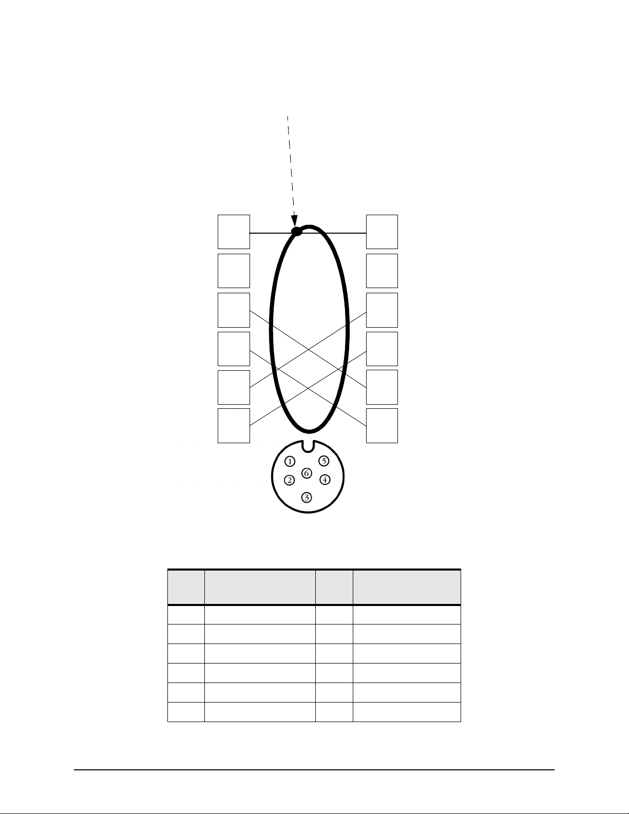
For wiring two 957’s, see Figure 17 on page 51 and
Table 8 on page 51.
•
For wiring a 957 to a 952/951/941, see Figure 18 on
page 52 and Table 9 on page 53.
2. Move to Step #3 on page 53.
Page 50 957 INSTALLATION MANUAL, Revision C1
Page 55
Shield termination
SECTION SIX: Interfacing the 957 system
957 6-PIN AUX CONNECTOR
Ground/shield
No connect
Aux input B
Aux output A
Aux output B
Aux input A
Pin number
1
2
3
4
5
6
957 6-PIN AUX CONNECTOR
Pin number
Ground/shield
1
No connect
2
Aux input B
3
Aux output A
4
Aux output B
5
Aux input A
6
Figure 17: 957 aux ports’ interface diagram (wiring side view, solder cup)
Table 8: 957 to 957 wiring
957
Pin #
1 Ground shield 1 Ground shield
2 No connect 2 No connect
3 Aux In B 5 Aux Out B
4 Aux Out A 6 Aux In A
5 Aux Out B 3 Aux In B
6 Aux In A 4 Aux Out A
957 INSTALLATION MANUAL, Revision C1 Page 51
Function 957
Pin #
Function
Page 56
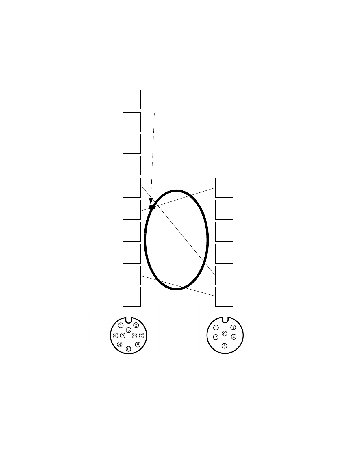
SECTION SIX: Interfacing the 957 system
952/951/941 10-PIN
AUX CONNECTOR
Pin number
No connect
No connect
No connect
No connect
Aux input B
Ground/shield
Aux output B
Aux input A
1
Shield
termination
2
3
957 6-PIN
AUX CONNECTOR
Pin number
4
5
6
Ground/shield
1
No connect
2
Aux input B
7
8
3
Aux output A
4
Aux output A
9
No connect
10
Aux output B
5
Aux input A
6
Figure 18: 952/951/941 and 957 aux ports’ interface diagram (wiring side view,
solder cup)
Page 52 957 INSTALLATION MANUAL, Revision C1
Page 57
SECTION SIX: Interfacing the 957 system
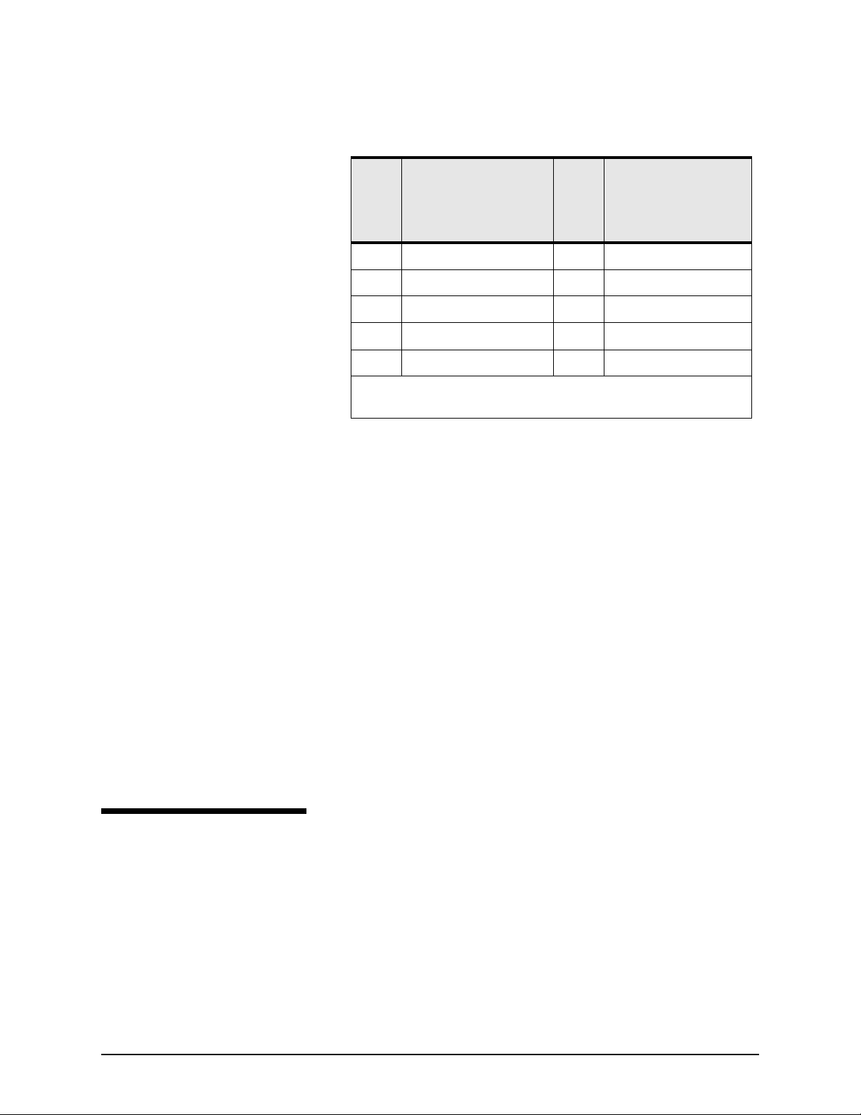
Table 9: 952/951/941 to 957 wiring
952
951
941
Pin #
5 Aux In B 5 Aux Out B
6 Ground shield 1 Ground shield
7 Aux Out B 3 Aux In B
8 Aux In A 4 Aux Out A
9 Aux Out A 6 Aux In A
*Pins 1, 2, 3, 4 and 10 on the 941/951/952 aux connector, and pin 2
on the 957 aux connector, aren’t used.
3. Slide the twist lock onto the connector body.
4. Screw the connector backshell to the connector body, and
tighten.
5. Install the strain- relief clamp with two screws.
6. Connect each end of the cable into the 6-pin ports at the
back of the 957, or connect one end of the cable into the
10-pin port at the back of the 941, 951, or 952.
7. Turn both units on, and test for the proper cable connec-
tion: a) Press the WAYPTS/ROUTES key; b) Press the
IMPORT/EXPORT menu key; c) Press the IMPORT DATA
or EXPORT DATA menu key; d) Press the TEST COMM
menu key.
8. The message should read REMOTE LINK OK. If so, the
hardware connection is now complete and the two units
can now transfer all waypoints and routes between them.
Function 957
Pin #
Function
Setting the
anchor-watch
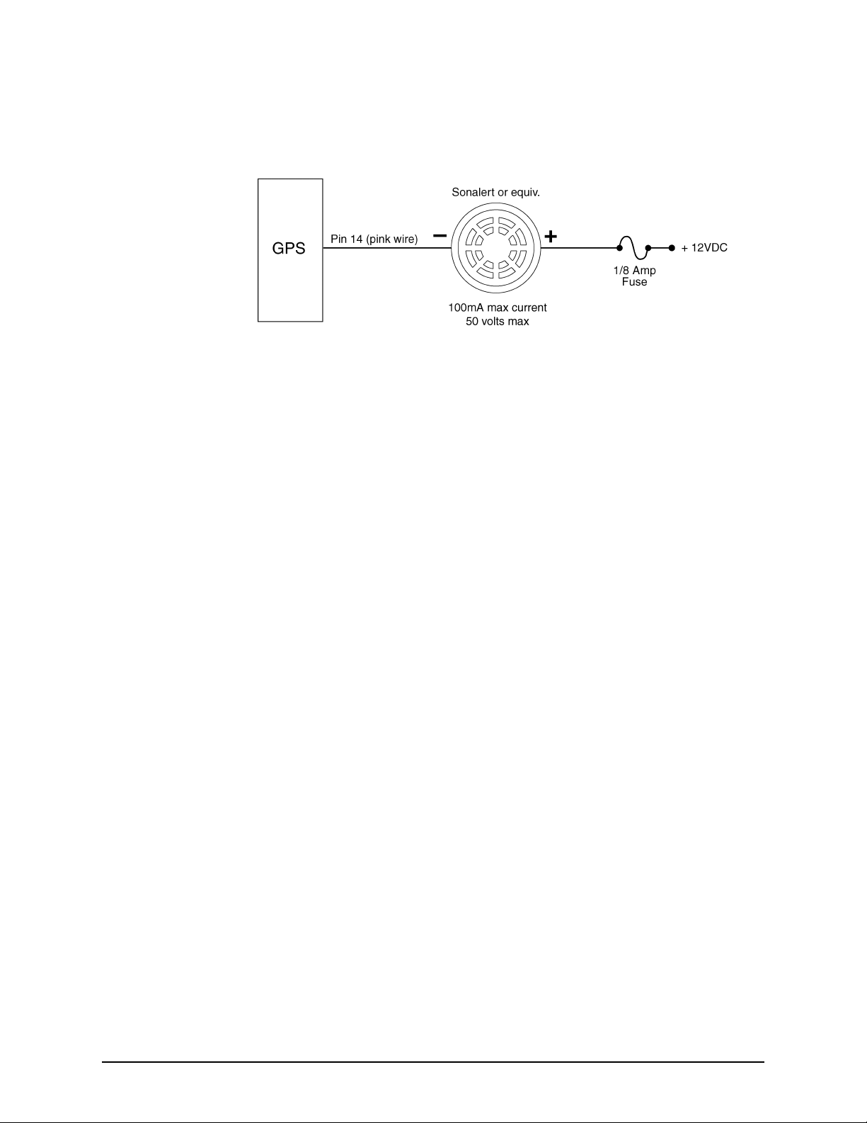
The anchor-watch alarm function is used to set the 957 to
honk, in addition to beep, once you’ve connected a honker to
pin #14 on the 957’s NMEA connector. See Figure 19 below for
alarm honk
957 INSTALLATION MANUAL, Revision C1 Page 53
Page 58
SECTION SIX: Interfacing the 957 system
the wiring to support the 957’s external honk feature. You can
use Radio Shack part number 273-060 or an equivalent.
Figure 19: Pin 14 honk alarm connection
A continuous honking sequence will begin, either when the
vessel moves outside the specified anchor-alarm radius or
when the navigation source becomes unavailable—once you’ve
set the anchor-watch alarm to honk. For detailed instructions
about this feature, see the Northstar 957 Operator’s Manual
(part number GM957UG).
Page 54 957 INSTALLATION MANUAL, Revision C1
Page 59
Troubleshooting
SECTION SEVEN: Troubleshooting and servicing the 957 system
957 installation
problems
Table 10: Troubleshooting the 957 installation
Problem Area Symptom Possible Solutions/Reasons
POWER
DISPLAY
Pressing the
•
957
The 957 powers up, beeps, but there
•
isn’t any video.
Typical problems that may occur during or after the 957’s
installation are described in the tables below.
key doesn’t start the
PWR
Check the fuse and the power to the
•
957.
The display may have failed. Call your
•
Northstar dealer or the Northstar
Service Department.
957 INSTALLATION MANUAL, Revision C1 Page 55
Page 60

SECTION SEVEN: Troubleshooting and servicing the 957 system
Table 10: Troubleshooting the 957 installation (continued)
Problem Area Symptom Possible Solutions/Reasons
DISPLAY (cont.)
SYSTEM
System lock-ups
The display screen dims, either slightly
•
or more, after the 957 has been on for a
certain time.
The message
•
where the video input image should be.
Color bars appear where the video
•
overlay image should be.
Hardware-related:
The system locks up on a random basis
•
with no apparent pattern.
8117 FAILURE
appears
The 957 may be implementing its
•
auto-dimming mode. Auto-dimming
helps maintain the integrity of the
display and reduce power
consumption when the 957 is on and
running too hot for its current
environment. In this case the display
screen may automatically dim.
The internal 8117 has failed; contact
•
the Northstar Service Department.
(This failure affects only the video
image, nothing else.)
Check that the video image is turned
•
on (press
VIDEO SETUP
Check the cables and the connectors.
•
Check that the video equipment is
•
working properly.
Possible internal hardware failure; call
•
the Northstar Service Department.
STAR
screen).
to display the
Possible bad chart card. Remove the
The system locks up when using a chart
•
card.
System fails any initial self-tests.
•
Page 56 957 INSTALLATION MANUAL, Revision C1
•
card, and inspect the pin area of the
card and the 957 for damage. If the
pins in the 957 are bent or damaged,
to prevent further damage, don’t
insert another card. If you’re sure that
the card pins aren’t bent, try inserting
a new card (turn power off before
inserting the card).
Possible internal hardware or
•
software failure; call the Northstar
Service Department.
Page 61

SECTION SEVEN: Troubleshooting and servicing the 957 system
Table 11: Troubleshooting the 2201 installation
If . . . Then . . .
Satellite signals are often lost, or the 2201
works while you’re travelling in one
direction, but not the opposite one.
Poor SNR readings are obtained even
after running the 957 for several minutes
You’re having difficulty obtaining WAAS
satellites
The following error message appears on
the 957 display:
The 2201 may be partially shaded by metallic objects around it.
Re-position or raise the 2201 away from the object for a better
satellite view.
Signals may be lost when the 2201 is under a bridge or when shielded
by buildings.
Check the quality of the antenna location—the antenna should have a
clear view of the sky. For the correct antenna placement, see Figure 8
on page 19.
Make sure the antenna is clean, and not covered with ice, snow, or
exhaust soot.
Check that WAAS is available in your operating area.
Reset the 957’s satellite elevation setting to its default (10 degrees).
Check that the 957’s
or
either
WAAS
AUTO.
DIFFERENTIAL OPERATIONS
option is set to
COMM FAIL
TOO FEW SATS
With power on, check the antenna and wiring connections.
Disconnect the 2201 from the 957, then measure the 7-pin 2201
connector for 10 - 36 volts at pin 7, ground at pin 6.
Check the 2201’s remote-on: Pin 5 should measure less than 5 ohms
to ground.
key to
After testing above, re-connect the cable and press the
turn the 957 off, then turn it back on again.
Check if anything is blocking the 2201’s view of the sky.
The almanac may not be complete; allow up to 30 minutes for full
initial acquisition.
PWR
957 INSTALLATION MANUAL, Revision C1 Page 57
Page 62

SECTION SEVEN: Troubleshooting and servicing the 957 system
Table 12: Troubleshooting the 2701 and AN205-P installation
If . . . Then . . .
Satellite signals are often lost, or the
AN205-P works while you’re travelling in
one direction, but not the opposite one.
Poor SNR readings are obtained even
after running the 957 for several minutes
You’re having difficulty obtaining WAAS
satellites
The following error message appears on
the 957 display:
COMM FAIL
The antenna may be partially shaded by metallic objects around it.
Re-position or raise the antenna away from the object for a better
satellite view.
Signals may be lost when the antenna is under a bridge or when
shielded by buildings.
Check the quality of the antenna location—the antenna should have a
clear view of the sky.
Make sure the antenna is clean, and not covered with ice, snow, or
exhaust soot.
Check that WAAS is available in your operating area.
Reset the 957’s satellite elevation setting to its default (10 degrees).
Check that the 957’s
or
WAAS
either
With power on, check the antenna and wiring connections.
DIFFERENTIAL OPERATIONS
.
AUTO
option is set to
Disconnect the 2701 from the 957, then measure the 25-pin 2701
connector for 10 - 36 volts at pin 25, ground at pin 13.
Check the 2701’s remote-on: Pin 12 should measure less than 5
ohms to ground.
After testing above, re-connect the cable and press the
turn the 957 off, then turn it back on again.
TOO FEW SATS
Page 58 957 INSTALLATION MANUAL, Revision C1
Check if anything is blocking the 2701’s or antenna’s view of the sky.
The almanac may not be complete; allow up to 30 minutes for full
initial acquisition.
PWR
key to
Page 63
Getting technical support
SECTION SEVEN: Troubleshooting and servicing the 957 system
Contacting Northstar
You can email the
Northstar Service
Department right from
Northstar’s website,
www.northstarcmc.com.
Here, you also can
access additional
technical information
under either the
Manuals
download manuals in
PDF form) or Support
links.
link (you can
After you’ve followed the instructions in this manual, if you
need technical assistance or have any other service-related
questions, you can contact the Northstar Service Department.
Please be as complete and accurate as possible when describing
the problem so that a service technician can research the
problem and provide the quickest response. You can reach
Northstar’s Service Department by email, fax, U.S. mail, or
phone as described in Table 13 below.
NOTE:
Northstar’s Service Department is available between 9:00 AM
and 5:00 PM Eastern Time, Monday through Friday, excluding
major holidays.
If you want to buy parts, or would like to request brochures or
have product questions, contact the Northstar Sales
Department, as described in the table below.
Please have the 957’s serial number — available
on the back of the unit or on the
SERVICE INFO
Northstar’s Service Department.
screen — ready before contacting
OPTIONS/
Table 13: Contacting Northstar
Email:
Service: [email protected]
Sales: [email protected]
Fax:
Service: 978/897-1595
Sales: 978/897-7241
Telephone:
Main number: 978/897-6600 or 800/628-4487
U.S. mail:
30 Sudbury Road
Acton, MA 01720 USA
957 INSTALLATION MANUAL, Revision C1 Page 59
Page 64

SECTION SEVEN: Troubleshooting and servicing the 957 system
Table 13: Contacting Northstar (continued)
Website:
www.northstarcmc.com (you can send email to
Northstar directly from this site)
Hearing from you
Using the Dealer
Express web pages
Online information
sources
Your feedback is important and helps Northstar ensure that this
manual is a valuable resource for all marine technicians. Email
your comments or suggestions about this manual to the
following address:
Northstar dealers can get service information online by going
to the Dealer Express area on Northstar’s website. Contact
Northstar for your dealer password before clicking on the
Dealer Express
•
service bulletins (for known issues and solutions)
•
software update information (for new software features)
•
service request form (for sending systems back)
•
service status request form (for systems currently under
repair)
•
warranty registration form (for registering new products)
For up-to-date WAAS information, visit the following websites:
•
The status of WAAS implementation:
http://gps.faa.gov/programs/waas/implementation_Status/
implementation_status.htm
link. This area includes the following topics:
•
U.S. government’s WAAS/GPS website:
http://gps.faa.gov
•
Stanford University’s WAAS Research Center:
http://www.stanford.edu/group/GPS/Projects/WAAS/metrics.html
Ordering replacement
parts
Obtaining software
updates
Page 60 957 INSTALLATION MANUAL, Revision C1
To order spare, replacement, or missing parts, call the Northstar
Sales Department at 978/897-6600 or 800/628-4487.
Periodically, Northstar posts 957 software-update addenda on
its website (www.northstarcmc.com) under the Manuals
link.
Page 65

SECTION SEVEN: Troubleshooting and servicing the 957 system
For dealers
Once Northstar has posted an addendum to its website, you
can call the Northstar Sales Department to order the
corresponding software update, or download the update from
the Dealer Express area of the website.
For operators
957 end users should contact their respective dealer for
software updates. Northstar does not recommend that
operators install software updates. If an update is installed
incorrectly by mistake, you could lose data and the 957 may
not function correctly. Software updates aren’t covered by the
Northstar warranty.
Servicing the 957 system
957 repairs are performed only by authorized Northstar dealers
or at the Northstar factory. Service includes a complete
hardware and software check-out.
NOTE:
For 957’s that are still under warranty, field repairs are not
authorized and will void the warranty! Please contact the
Northstar Customer Service Department if you need
clarification, or need assistance with having repairs done.
For a system under warranty, shipping charges to the factory
are the only cost for factory repair. The repaired 957 will be
returned via prepaid economy ground freight (units returned
overseas are chargeable).
The 957 and any accessories returned for warranty repair that
are determined to be without fault are subject to a handling
charge.
957 INSTALLATION MANUAL, Revision C1 Page 61
Page 66
SECTION SEVEN: Troubleshooting and servicing the 957 system
Returning a 957 system for service
Before returning the
957 to the Northstar
factory, to prevent
delays, it is critical that
you first obtain a
Return Materials
Authorization (RMA)
number from the
Northstar Service
Department. If the 957
was purchased
through a dealer, call
the dealer with the 957
serial number so they
can help you get an
RMA number. The
957’s serial number is
on the label at the
back of the unit.
Shipments without a
proper RMA number
will not be accepted!
CAUTION!
You may want to back-up any user-defined waypoints and
routes before returning the 957 for repair. See the Northstar
957 Operator’s Manual for details.
The 957 is covered by a two-year hardware-only warranty,
which, in summary, states that if the unit is returned to the
factory by the owner or dealer during the warranty period,
Northstar will repair or replace, free of charge, any part found
to be defective due to faulty materials or workmanship if the
system has been properly installed and hasn’t been abused. See
the Limited Warranty Policy at the front of this manual for
further details. The only cost to the owner will be the one-way
shipping charges and any associated charges that may be
imposed by the dealer. If you have overnight or second-day
shipping requirements, before shipping the unit, please call the
factory for turnaround time, freight charges, and payment
arrangements.
The 957 should be shipped only in a properly designed carton
with packing material, and to the Northstar factory at the
following address:
Northstar Technologies
Service Department
30 Sudbury Road
Acton, MA 01720 USA
Maintaining the 957
Basic maintenance
Page 62 957 INSTALLATION MANUAL, Revision C1
At the end of the day, wipe the 957 off with a damp cloth.
Cover it with the sunshield to protect it from excessive heat.
Page 67
APPENDIX A: 957 system technical specifications
Table 14: 957 technical specifications
Physical features/environmental Interfacing
Waterproof control head Two bi-directional NMEA I/O ports, 1 AUX port
10.4” diagonal color LCD Two bi-directional RS-232 ports
Unsurpassed sunlight viewability Interfaces to optional Northstar 490 for fishfinding
640x480 pixel, hi-temp, backlit, transmissive color
LCD
Flush mount standard
High-contrast anti-reflective screen
Waterproof chart cartridge door
Large, easy-to-use backlit controls One VIDEO in port
Easy interfacing I/O plugs NMEA input sentences: WPL and others
0 degrees Celsius - 55 degrees Celsius max 95%
relative humidity, noncondensing
10 - 36 volts DC power
Waypoint upload/download capability to a PC (with
appropriate software)
One VGA out port (connects to Northstar 1201
monitor and others)
200 PPNM speed output
Honk output
NMEA output sentences: APB, BOD, BWC, GGA,
GLC, GLL, GSA, GSV, LCD, HSC, MSS, RNN, RMC,
RMA, RMB, VTG, WCV, XTE, ZDA, ZTG. (Conforms
to NMEA v 2.0 and later. Supports 1.5 GLL and
BWC.)
Accepts most external loran receivers
Waypoint and route transfer between two 957’s (or a
957 and a Northstar 941/951/952)
957 INSTALLATION MANUAL, Revision C1 Page 63
Page 68

APPENDIX A: 957 system technical specifications
Table 15: 2201 technical specifications
Physical features Interfacing
Self-contained 12-channel L1 GPS/WAAS pod
antenna-receiver.
Dimensions: 4.5" (114mm) diameter x 3.79" (96mm)
high.
Weight: 1.2 lb. maximum excluding cable (0.55 kg).
Cable (normal installation): 22 Ga conductors
foil-shielded cable, environmentally sealed (50-foot
cable supplied).
Mounting: 1-14 UNS threads x 1" deep for mast
mounting, and 3 x 10-32 UNF screws for deck
mounting.
Connector receptacle with 7 male contacts. Mating:
Switchcraft EN3C7FC or equivalent.
Prime power:10 to 36 VDC (12V and 24V system).
2.4 watts typical at 12V. Reverse polarity protected
and load dump protected.
Input messages:Auxiliary (RTCM SC104) messages
1, 3, 9. Output messages: NMEA GGA, GSA, GSV,
RMC, VTG, ZDA, GLL.
Serial communications: RS-232 asynchronous data
port, Main port IN/OUT plus AUX input; 19,200 baud
standard (both ports user-selectable from 300 to
19,200 baud). Default baud rate = 9600.
Performance Environmental
Acceleration: 4 Gs (39.2 m/s2), Jerk: 2 m/s
Velocity: 1852 km/h (514 m/s) max. Storage temperature: -55 to +90°C.
Position accuracy: <3 m 2dRMS. Humidity: SAE J1455/4.2 Procedure I/II.
Time-to-first-fix (TTFF): Hot start - 20 seconds typical,
with current almanac. Warm start - 45 seconds
typical, with current almanac. Cold start - 2 minutes
typical, with no almanac.
Re-acquisition time: <1 second typical to re-acquire
(five-second obscuration). 3 seconds typical to
re-acquire (60-minute obscuration).
Channel allocation: 10 GPS channels plus two WAAS
satellites.
Coarse acquisition: C/A code (1.023 MHz chip rate),
code and carrier phase tracking.
Sensitivity: -135 dBm (antenna input level).
3
Operating temperature: -30 to +75°C (standard).
Waterproof: Fully sealed unit. Meets MIL-STD 810E
method 512.3 (equivalent to 6-foot, 30-minutes
submersion).
Shock: MIL-STD 810E Method 506.4, Procedure I,
IV.
Vibration: MIL-STD 810E Method 514.4 Category 8.
Salt spray: MIL-STD 810E Method 509.3 (48 hours).
Sand and dust: MIL-STD 810E Method 510.3.
ESD: IEC 1000-4-2 level 2 (-8 kV to +8 kV).
EMI: FCC Class B, European CE, 89/EEC EN55022
class B, EN50082-1.
Ultraviolet light protection: ASTM G53-88.
Page 64 957 INSTALLATION MANUAL, Revision C1
Page 69

Table 16: 2701 technical specifications
Physical features Interfacing
APPENDIX A: 957 system technical specifications
Dimensions: 2.0” high x 4.68” wide x 8.9” deep
Weight: 2 pounds
Primary power: 10 to 40 VDC (12V and 24V
systems). 10 watts typical.
RS-232, GPS, and beacon receiver comm ports
Performance Environmental
Velocity: 1852 km/h (514 m/sec) max.
Acceleration: 4 Gs (39.2 m/sec
Position accuracy: < 1 m circular error probability
(CEP), DGPS; < 2 m circular error probability (CEP),
WAAS.
Time-to-first-fix (TTFF): Hot start - 20 seconds typical,
with current almanac, position, time, and ephemeris.
Warm start - 45 seconds typical, with current
almanac, position, time, and ephemeris. Cold start - 2
minutes typical, no almanac, position, and time. With
WAAS acquisition, add 30 seconds typical (max. 1
minute)
Re-acquisition time: < 1 second typical to re-acquire
(5-second obscuration); 3 seconds typical to
re-acquire (60-minute obscuration).
Channels allocation: 10 GPS channels plus two
WAAS satellites.
2
, Jerk: 2 m/sec
3
Operating temperature Receiver: 0 degrees C to +50 degrees C.
Antenna/preamp: - 40 degrees C to +50 degrees C.
957 INSTALLATION MANUAL, Revision C1 Page 65
Page 70

APPENDIX A: 957 system technical specifications
Page 66 957 INSTALLATION MANUAL, Revision C1
 Loading...