

Page 1

Northstar 972
Quickstart Guide
and
Reference Manual
Revision B
Page 2

Attention Installers:
This processor module must be handled with reasonable care and protected from the following;
• Moisture: Do not mount this processor in unprotected areas of the vessel having moisture.
• Vibration and shock: Use of the supplied shock/vibration mount is a mandatory part of the
installation. Only mount this unit in a horizontal position with adequate space for ventilation,
maintenance and for field service removal. Rough handling during removal or installation can
cause premature failure of internal components.
• Radar interference: Do not install the processor or cabling in areas exposed to interference from
any radar. The processor should be mounted as far as possible below any source of radar
interference.
Flybridge installations of the processor are not recommended and should be avoided. Installations
in these areas require special provisions for shielding and the installation design must provide total
protection from any moisture.
Problems caused by moisture, vibration and radar interference are not covered by warranty. Refer
to the installation manual P/N GM972IM for additional installation, troubleshooting and warranty
information.
For advice regarding equipment placement, please consult with an authorized Northstar Servicing
Dealer before beginning the installation.
To locate a Northstar Servicing Dealer near you call 978-897-6600
Page 3

Contents
Getting Started . . . . . . . . . . . . . . . . . . . . . . . . . . . . . . . 1
Welcome to the Northstar 972. . . . . . . . . . . . . . . . . . . . 2
Using this manual. . . . . . . . . . . . . . . . . . . . . . . . . . . . . . . 2
Networking the 972. . . . . . . . . . . . . . . . . . . . . . . . . . . . . 3
Interfacing the 972. . . . . . . . . . . . . . . . . . . . . . . . . . . . . . 4
Maintaining the 972 . . . . . . . . . . . . . . . . . . . . . . . . . . . . 4
Technical support . . . . . . . . . . . . . . . . . . . . . . . . . . . . . . . 5
Electronic Charts and the 972 . . . . . . . . . . . . . . . . . . . . 6
Purchasing charts . . . . . . . . . . . . . . . . . . . . . . . . . . . . . . . 7
Quickstart Guide
Northstar 972 Quickstart Guide . . . . . . . . . . . . . . . . . 9
Turning the 972 on and off . . . . . . . . . . . . . . . . . . . . . 11
Introducing the display screen . . . . . . . . . . . . . . . . . . . 11
Introducing the controls . . . . . . . . . . . . . . . . . . . . . . . . 12
Detailed chart data. . . . . . . . . . . . . . . . . . . . . . . . . . . . . 13
Displaying the chart screen. . . . . . . . . . . . . . . . . . . . . . 14
Displaying the chart screen. . . . . . . . . . . . . . . . . . . . . . 14
Using demo mode . . . . . . . . . . . . . . . . . . . . . . . . . . . . . 19
Displaying numeric data on the chart screen. . . . . . . 19
Displaying numeric data on the position screen . . . . 20
Going immediately to a quick waypoint . . . . . . . . . . . 21
Radar . . . . . . . . . . . . . . . . . . . . . . . . . . . . . . . . . . . . . . . . 22
The echo sounder . . . . . . . . . . . . . . . . . . . . . . . . . . . . . 23
Split function . . . . . . . . . . . . . . . . . . . . . . . . . . . . . . . . . . 23
The STAR key: alarms, TideTrack and setup . . . . . . . 24
SAVE and Man Overboard (MOB). . . . . . . . . . . . . . . . . 25
Reference Sections
1 Using the Chart Screen . . . . . . . . . . . . . . . . . . . . . . . . 27
Using electronic charts . . . . . . . . . . . . . . . . . . . . . . . . . . 28
Zooming in and out . . . . . . . . . . . . . . . . . . . . . . . . . . . . 28
Using the cursor on the chart screen . . . . . . . . . . . . . . 29
Comparing vessel and browse modes . . . . . . . . . . . . . 29
Rotating the chart . . . . . . . . . . . . . . . . . . . . . . . . . . . . . . 31
Setting up the chart screen . . . . . . . . . . . . . . . . . . . . . . 33
Using the course predictor line . . . . . . . . . . . . . . . . . . . 38
Using the distance and bearing calculator. . . . . . . . . . 38
2 3D maps. . . . . . . . . . . . . . . . . . . . . . . . . . . . . . . . . . . . . 41
Introduction to 3D images . . . . . . . . . . . . . . . . . . . . . . . 42
Configuring the screen . . . . . . . . . . . . . . . . . . . . . . . . . . 43
Flying around the vessel . . . . . . . . . . . . . . . . . . . . . . . . 44
3 Position coordinates . . . . . . . . . . . . . . . . . . . . . . . . . . 45
Displaying position, COG, and speed . . . . . . . . . . . . . . 46
Using GPS . . . . . . . . . . . . . . . . . . . . . . . . . . . . . . . . . . . . . 46
Position screen options . . . . . . . . . . . . . . . . . . . . . . . . . 47
Viewing GPS satellite status . . . . . . . . . . . . . . . . . . . . . . 48
Using Phantom Loran . . . . . . . . . . . . . . . . . . . . . . . . . . . 49
4 Navigating to Waypoints . . . . . . . . . . . . . . . . . . . . . . 51
Introducing waypoints . . . . . . . . . . . . . . . . . . . . . . . . . . 52
Designating a waypoint . . . . . . . . . . . . . . . . . . . . . . . . . 52
Steering to a waypoint . . . . . . . . . . . . . . . . . . . . . . . . . . 54
The course predictor line . . . . . . . . . . . . . . . . . . . . . . . . 57
Navigating along routes . . . . . . . . . . . . . . . . . . . . . . . . . 58
Restarting the track line . . . . . . . . . . . . . . . . . . . . . . . . . 59
Page 4

The NAVLOG screen . . . . . . . . . . . . . . . . . . . . . . . . . . . 60
5 Creating waypoints and routes . . . . . . . . . . . . . . . . 63
Displaying waypoints. . . . . . . . . . . . . . . . . . . . . . . . . . . 64
Creating new waypoints . . . . . . . . . . . . . . . . . . . . . . . . 65
Creating avoidance-area waypoints . . . . . . . . . . . . . . 68
Editing waypoints . . . . . . . . . . . . . . . . . . . . . . . . . . . . . . 69
Introducing routes . . . . . . . . . . . . . . . . . . . . . . . . . . . . . 71
Creating a route from the chart . . . . . . . . . . . . . . . . . . 72
Creating routes from a list of waypoints . . . . . . . . . . . 73
Saving a route as you travel . . . . . . . . . . . . . . . . . . . . . 74
Editing a route. . . . . . . . . . . . . . . . . . . . . . . . . . . . . . . . . 76
Transferring waypoints/routes to other units. . . . . . . 80
Transferring waypoints to and from a PC. . . . . . . . . . 83
6 Radar. . . . . . . . . . . . . . . . . . . . . . . . . . . . . . . . . . . . . . . 85
How radar works . . . . . . . . . . . . . . . . . . . . . . . . . . . . . . 87
Displaying radar . . . . . . . . . . . . . . . . . . . . . . . . . . . . . . . 87
Turning the radar transmitter on and off . . . . . . . . . . 87
Overlaying radar on the chart . . . . . . . . . . . . . . . . . . . 90
Changing radar scale and rotation . . . . . . . . . . . . . . . 90
Using the radar’s main menu keys . . . . . . . . . . . . . . . 88
Using the Adjustment keys . . . . . . . . . . . . . . . . . . . . . . 91
Using the Markers keys . . . . . . . . . . . . . . . . . . . . . . . . . 94
Radar cursor . . . . . . . . . . . . . . . . . . . . . . . . . . . . . . . . . . 96
MARPA targets . . . . . . . . . . . . . . . . . . . . . . . . . . . . . . . . 96
The picture menu . . . . . . . . . . . . . . . . . . . . . . . . . . . . . 114
Changing the depth settings . . . . . . . . . . . . . . . . . . . . 116
Using the MORE key . . . . . . . . . . . . . . . . . . . . . . . . . . . 117
Setting the ECHO screen data . . . . . . . . . . . . . . . . . . . 119
Viewing past echoes using SoundTrac . . . . . . . . . . . . 120
Echo sounding alarms . . . . . . . . . . . . . . . . . . . . . . . . . 121
8 Video . . . . . . . . . . . . . . . . . . . . . . . . . . . . . . . . . . . . . . 127
Video sources. . . . . . . . . . . . . . . . . . . . . . . . . . . . . . . . . 128
Displaying video . . . . . . . . . . . . . . . . . . . . . . . . . . . . . . 128
9 Alarms and TideTrack . . . . . . . . . . . . . . . . . . . . . . . . 131
Alarms. . . . . . . . . . . . . . . . . . . . . . . . . . . . . . . . . . . . . . . 132
TideTrack™ . . . . . . . . . . . . . . . . . . . . . . . . . . . . . . . . . . . 137
10 Networking . . . . . . . . . . . . . . . . . . . . . . . . . . . . . . . . 141
General information . . . . . . . . . . . . . . . . . . . . . . . . . . . 142
Restrictions . . . . . . . . . . . . . . . . . . . . . . . . . . . . . . . . . . . 142
11 Setup. . . . . . . . . . . . . . . . . . . . . . . . . . . . . . . . . . . . . . 145
972 configuration . . . . . . . . . . . . . . . . . . . . . . . . . . . . . 146
Navigation options . . . . . . . . . . . . . . . . . . . . . . . . . . . . 147
Changing your port settings . . . . . . . . . . . . . . . . . . . . 151
Setting up the echosounder. . . . . . . . . . . . . . . . . . . . . 151
Installing software updates . . . . . . . . . . . . . . . . . . . . . 151
Diagnostics . . . . . . . . . . . . . . . . . . . . . . . . . . . . . . . . . . . 152
Changing the time zone . . . . . . . . . . . . . . . . . . . . . . . . 153
7 Echo sounding. . . . . . . . . . . . . . . . . . . . . . . . . . . . . . 101
Welcome to the Northstar Echo Sounder . . . . . . . . . 103
Displaying the echo sounder’s picture . . . . . . . . . . . 106
Using automatic mode . . . . . . . . . . . . . . . . . . . . . . . . 107
Changing the frequency of echoes . . . . . . . . . . . . . . 108
Zooming in and out . . . . . . . . . . . . . . . . . . . . . . . . . . . 109
Echo Sounder setup . . . . . . . . . . . . . . . . . . . . . . . . . . . 112
Appendix A — Datum list . . . . . . . . . . . . . . . . . . . . . 155
Appendix B — Specifications . . . . . . . . . . . . . . . . . . 161
Page 5

Getting Started
Welcome to the Northstar 972. . . . . . . . . . . . . . . . . . . . . . . . . . 2
Using this manual . . . . . . . . . . . . . . . . . . . . . . . . . . . . . . . . . . . . 2
Maintaining the 972. . . . . . . . . . . . . . . . . . . . . . . . . . . . . . . . . . . 4
Interfacing the 972. . . . . . . . . . . . . . . . . . . . . . . . . . . . . . . . . . . . 4
Technical support. . . . . . . . . . . . . . . . . . . . . . . . . . . . . . . . . . . . . 5
Electronic Charts and the 972. . . . . . . . . . . . . . . . . . . . . . . . . . . 6
Purchasing charts . . . . . . . . . . . . . . . . . . . . . . . . . . . . . . . . . . . . . 7
This chapter introduces this manual and explains a few things you should know to keep
your Northstar 972 in top operating condition.
Reference Manual Revision B
1
Page 6
Welcome to the Northstar 972
Congratulations on your purchase of the
Northstar 972 Integrated Navigation
The 972 has several
requirements that must
be met to ensure safe
and proper operation.
Installation and interfacing of the 972 should be
handled by a marine
technician using the
guidelines found in the
Northstar 972 Installation Manual.
System! The 972 is a full-featured 3D color
GPS/vector charting system — easy to use,
but meeting your marine navigation needs
in a comprehensive, logical manner.
Optional Northstar radar and fish finding
modules round out the 972’s capabilities.
The 972 enhances GPS with the Wide Area
Augmentation System (WAAS) for superb
accuracy, and offers a high-resolution
full-color screen with Jeppesen Marine and
BSB cartography.
Using this manual
Major functions are accessed with a single
keypress. By reducing the attention
required to navigate, you can devote more
time to simply enjoying your trip.
For information on installing, interfacing,
and troubleshooting the 972, please see
the Northstar 972 Installation Manual (part
number GM972IM) or contact your local
authorized Northstar dealer.
2
This manual is divided into two main
sections:
• The Quickstart Guide begins on page 9
• A Reference Section starts on page 27.
Getting Started
Welcome to the Northstar 972
and has all the basic information you
need to operate the 972. Be sure to read
this section as you start using the unit.
Use this when you need more
information about any of the unit’s
functions — you’ll find answers here to
any questions about getting the most
from your 972.
Check the mini table of contents at the
beginning of each chapter to quickly locate
a topic you need help with.
It’s best to read this manual with the 972
set up and running so you can try out the
various functions and see the results.
Conventions
This manual uses certain conventions to
provide a consistent means of recognizing
specific information, as follows:
Northstar 972
Page 7
• is the universal caution symbol for
caution and warning information
related to your personal safety or
possible damage to the system. The
CAUTION and WARNING notes contain
critical information—please read them!
• The phrase “Press a key” means push
briefly and release, unless otherwise
specified. “Press and Hold” means to
hold the key until the desired result
occurs.
Networking the 972
• Text written like “CHART” generally
refers to named keys on the 972’s front
panel.
• Text written like “More info” generally
refers to the 972’s menu keys at the
right side of the screen.
• Whenever this manual tells you to
press
ENTER to perform a function, you
can press
CLEAR instead if you decide
not to perform that function. These
keys are abbreviated
ENT and CLR on
the 972.
Reference Manual Revision B
Northstar’s networking technology lets you
connect two or more 972 units in order to
share navigation data (including radar and
sounder data) and all waypoints and routes
between the units. The system can be
operated from any connected unit, and all
changes to routes and waypoints are
reflected on all the networked units.
Networking is fully automatic on the 972 —
no special steps are necessary
One display unit is designated as the
master, and all others as slaves. The only
restrictions on networking are the
following:
• there must be one and only one master
unit operating in a network
• all units must have the same software
version.
If, for example, a slave unit is turned on
before the master, a message is displayed
reminding you to turn on the master unit
before using the slave. In case the master
unit is not available (removed for service,
for example), brief instructions show how
to temporarily convert a slave into a master
unit.
For details on networking, see Networking,
starting on page 141.
Getting Started
Networking the 972
3
Page 8

Interfacing the 972
The 972 can be connected to a wide
variety of compatible marine devices,
including Northstar’s echo sounder and
radar. A qualified marine electronics tech-
Maintaining the 972
Basic maintenance
To help retain the 972’s best possible
performance, Northstar recommends the
following:
• keep fingerprints off the display screen
(remove any prints with a lens cleaning
cloth)
• remove dirt and grime using a soft
cloth and Windex or soap and water
• don’t scratch the display by wiping a
Pre-packaged moist
towellettes (especially
those containing a small
amount of alcohol) are
excellent for cleaning
the display window. You
might want to keep a
supply on hand to wipe
off fingerprints and other
smudges.
sandy or salty cloth across it
• use the 972’s protective plastic
sunshield when not in use (excessive
heat from the sun can cause damage)
• don’t open the 972 case—there aren’t
any user-serviceable parts inside
• always keep the rear connectors’ plastic
caps on when they are not in use (the
connectors are not waterproof unless
covered)
nician should perform these installations.
For details, contact your local authorized
Northstar dealer.
Cleaning the display screen
Be careful when cleaning the glass window
covering the display screen. Although the
window is scratch-resistant, you may
damage the anti-reflective coating if you
use a dry cloth to wipe dirt off. Always use
a damp cloth with plenty of water to
remove salt or dirt. To remove any oil or
grease on the screen, use a clean, dry
microfiber-type lens cleaning cloth or a
small amount of window cleaner.
Avoid touching the window with your
fingers. The natural oils from your hand
will temporarily affect the characteristics of
the screen and cause your fingerprints to
appear as bright reflections. Fingerprints
will disappear when you clean the screen
as described in the previous paragraph.
4
Getting Started
Interfacing the 972
Northstar 972
Page 9
Technical support
Northstar products are manufactured and
serviced by BNT Marine Electronics.
If you need technical support, or have any
other questions after you’ve followed the
instructions in this manual, you can
contact the factory as follows:
by Telephone:
978/897-6600 or 800/628-4487
by E-mail:
Service: [email protected]
Sales: [email protected]
by Fax:
Service: 978/897-1595
Sales: 978/897-7241
by U.S. mail:
Northstar
30 Sudbury Road
Acton, MA 01720 USA
Additional information is available at
Northstar’s website:
www.NorthstarNav.com
Hearing from you
Your feedback is important and helps
ensure that this manual is a valuable
resource for all 972 users. Send your questions, comments, or suggestions about this
manual to:
Service and repair
In case of a 972 operating problem, check
all interconnecting cables and fuses. If you
continue to have problems, contact your
dealer or the factory for additional assistance. If required, you can return the 972
to the factory for diagnosis and repair.
When calling, be sure to have your 972
serial number and software revision available. In describing a problem, be as
complete and accurate as possible. Before
returning the 972 for repair, you may want
to save your waypoints and routes. If the
unit is properly networked to another 972
display, a copy of your waypoints and
routes is already saved in the other unit.
You can also transfer data to a Northstar
6000 series or older navigator or to a PC as
described on pages 80 and 83.
Reference Manual Revision B
Getting Started
Technical support
5
Page 10
To prevent delays, it’s critical that you first
obtain a Return Materials Authorization
(RMA) number from our Service
Department before returning your 972.
Shipments to BNT Marine Electronics
should be made to the following address:
Electronic Charts and the 972
NOTE:
Northstar Service Department
30 Sudbury Road
Acton, MA 01720
If you have special overnight or
second-day shipping requirements, please
call for turnaround time and freight costs
before you ship your 972.
6
One of the 972’s unique features is the
ability to display both raster and vector
charts. In split screen mode, you can even
display a raster chart and a vector chart
side by side. This is a great way to understand the differences and similarities
between the two.
Raster Charts
Raster charts are literally digital scans of
paper charts. In most cases, these paper
charts are issued by the local government.
The scans, like digital photos, are a matrix
of dots. The challenge in raster charts —
the earth is round (3D) and the chart is flat
(2D) — is to be able to determine the
precise latitude and longitude of each dot
at any zoom level.
One of the biggest benefits of raster charts
is their appearance – it is identical to the
Getting Started
Electronic Charts and the 972
paper charts. It’s like having the paper
chart on the screen.
This is also one of the drawbacks to raster
charts. Since the chart is just a matrix of
dots, the chart plotter cannot tell the difference between a navaid and a depth
sounding. Furthermore, they really only
look great at one particular zoom level.
Zooming in or out from that level compromises display quality.
Vector Charts
Vector charts, on the other hand, are
drawn on the screen from a set of rules
specific to each chart — instead of a digitized photo of the chart, it’s a
mathematical description of the chart. The
chart plotter interprets the description and
then draws (renders) the chart. Whatever
the screen resolution or zoom level, they
always look great. Rather than being a
Northstar 972
Page 11
matrix of dots, the vector chart is a series
of lines and shapes. The shapes are then
filled in with colors.
Another advantage is the ability to “layer”
the data. The user can shut off certain
layers so the display is less cluttered.
One of the biggest benefits of vector charts
is that navaids and other points of interest
are specified in the chart data, so the
plotter can highlight navaids, and do intelligent things when the vessel or the cursor
gets near a navaid. This increased flexibility is virtually boundless in the power it
offers.
Purchasing charts
Purchasing charts for your 972 is quick
and easy, because all available charts are
Where to purchase
Passport Charts
You may purchase charts by
telephone at:
800 272 6205
or online at
www.PassportOnBoard.com
already stored on a hard disk drive in its
processor module. There’s no waiting for
delivery or visits to dealers — you only
need to purchase a chart permit to use
them.
To purchase additional charts:
One of the drawbacks of vector charts has
been that they don’t look identical to the
raster charts. With advances in technologies – both in cartography and marine
electronics – this disadvantage is
disappearing.
See page 28 for more on charts in the 972.
In addition, a menu key for purchasing
charts is displayed on the chart screen,
whenever there are additional charts that
you have not purchased, at the current
vessel position.
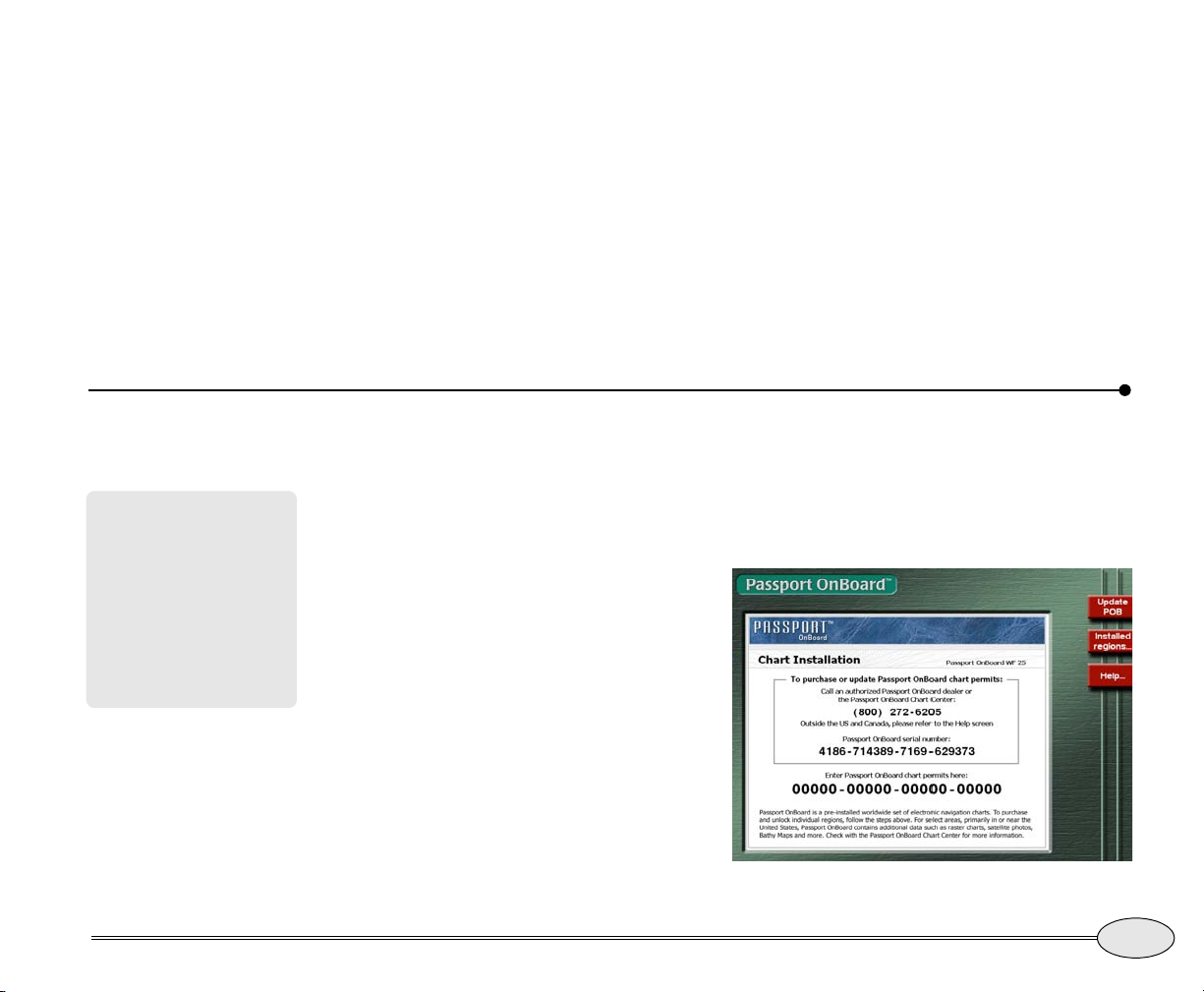
1. Press the STAR key several times to display
the Passport OnBoard screen.
2. Note the Passport OnBoard serial number,
and contact Jeppesen Marine by telephone or
the Internet to purchase the chart permits you
need.
3. Enter the chart permit and press ENTER.
4. Wait for the chart to be activated (up to five
minutes).
Reference Manual Revision B
Getting Started
Purchasing charts
7
Page 12

8
Getting Started
Purchasing charts
Northstar 972
Page 13

Northstar 972 Quickstart Guide
Turning the 972 on and off . . . . . . . . . . . . . . . . . . . . . . . . . . . 11
Displaying the chart screen . . . . . . . . . . . . . . . . . . . . . . . . . . . 14
Using demo mode . . . . . . . . . . . . . . . . . . . . . . . . . . . . . . . . . . . 19
Displaying numeric data on the chart screen . . . . . . . . . . . . 19
Displaying numeric data on the position screen . . . . . . . . . 20
Going immediately to a quick waypoint . . . . . . . . . . . . . . . . 21
Radar . . . . . . . . . . . . . . . . . . . . . . . . . . . . . . . . . . . . . . . . . . . . . . 22
The echo sounder. . . . . . . . . . . . . . . . . . . . . . . . . . . . . . . . . . . . 23
Split function. . . . . . . . . . . . . . . . . . . . . . . . . . . . . . . . . . . . . . . . 23
The STAR key: alarms, TideTrack and setup . . . . . . . . . . . . . 24
SAVE and Man Overboard (MOB). . . . . . . . . . . . . . . . . . . . . . . 25
This section gives an overview of each of the 972 major functions and the basic informa-
tion you need to begin using them.
We suggest you read this section carefully as you first use the 972 and then refer to the
following Reference Sections, as necessary, to answer any questions you may have.
Quickstart Guide Revision B - Review
9
Page 14
SPLIT
IN
OUT
BRT
DIM
WAYPTS
ROUTES
SAVE
PWR
CHART
POSITION
STEER
3D
RADAR
SOUNDER
VIDEO
MOB
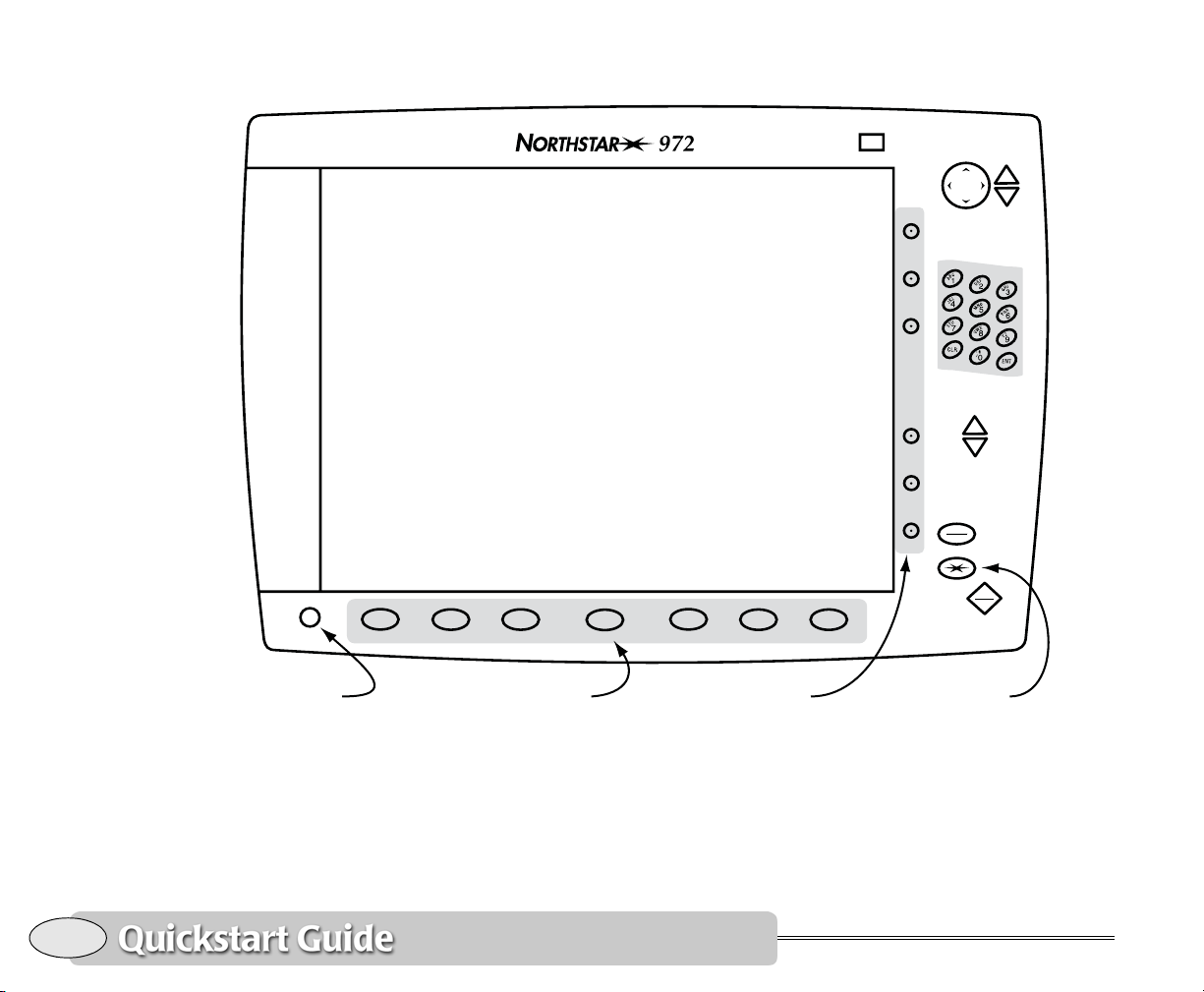
Function KeysPower Key Soft Keys STAR Key
10
Figure 1: 972 controls
Northstar 972
Page 15
Turning the 972 on and off
CAUTION!
Turning the 972 on
To turn the 972 on, gently and briefly press
the
Use caution when navigating with electronic
charts. Although every
effort has been made to
ensure that the data the
972 uses is as close as
possible to paper charts,
errors and omissions are
inevitable. The captain is
responsible for
cross-checking the 972
against other sources of
navigation data.
PWR key. (See Figure 1 on page 10 for a
picture of the controls.)
During the startup sequence, the 972
beeps and displays its start-up screen, and
then performs a series of self-tests to check
its critical components and functions. Any
startup issues are indicated by a double
asterisk on the screen.
Next, a message warns against relying on
the 972 chart cartography as the only
means of safe navigation. Acknowledge the
Introducing the display screen
Adjusting the brightness
To adjust the screen’s brightness press the
BRT or DIM key.
If the 972 becomes too hot due to high
ambient temperature and strong sunlight,
the display screen may automatically dim
to prevent overheating. You can temporarily override the auto-dim function at
any time just by increasing the brightness.
warning message by pressing the
CHART
key.
Now you’re ready to get underway with
your 972!
If this 972 was recently used at or near its
present location, it will usually be ready to
navigate within one minute after it is turned
on.
Turning the 972 off
To turn the 972 off, press and hold the
PWR key until the screen goes dark. Allow
up to 30 seconds for the black box to
power down.
The 972 may dim again to avoid exceeding
the maximum internal temperature.
Special display windows
Occasionally, the 972 needs to tell you
something or ask permission to do something. When this happens, an information
or question window appears on the screen.
This window may contain an alarm icon, or
Quickstart Guide Revision B
Turning the 972 on and off
11
Page 16
an INFO icon or a large question mark
along with a message for you to read.
For more on alarms, see ”Displaying alarm
messages” starting on page 132.
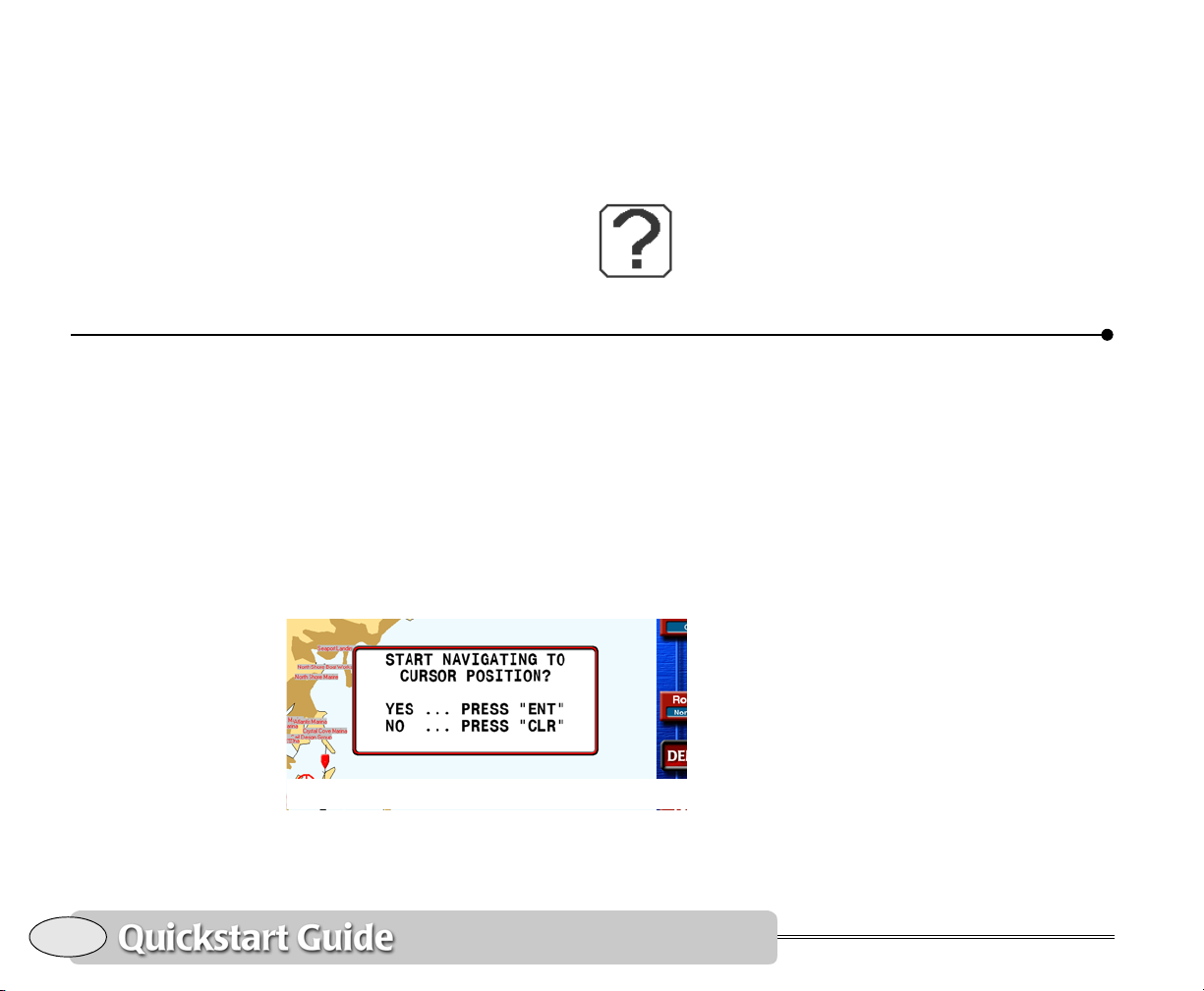
Question windows
A question window appears
when the 972 needs a
Introducing the controls
response from you. Respond to a question
window by pressing the
answer yes, or the
Most of the other keys, including the
function keys, are temporarily inactive
while the 972 displays a question window.
ENTER key to
CLEAR key to answer no.
12
Feel free to try any of the 972’s controls!
You can’t hurt anything, and you’ll only
learn more about how to use the 972 more
efficiently. The 972 always asks you to
verify what you’re doing before it changes
or deletes information. You’ll be asked to
confirm your action before anything
happens that may affect the 972’s operation. You can always press
a function if you change your mind.
Using ENTER and CLEAR
Introducing the controls
CLEAR to cancel
Function keys
Figure 1 on page 10 illustrates the locations of the 972’s controls.
The seven keys below the screen access
the unit’s major functions. These are
CHART, POSITION, STEER and 3D, and the
optional functions
VIDEO. Press one at any time to instantly
display that function on the full screen,
then use the menu keys at the right edge
of the screen to control the function.
The
WAYPTS/ROUTES key accesses the
972’s database of stored position
information.
The
STAR key accesses the alarm screen
and miscellaneous functions including
TideTrack and setup commands.
RADAR, SOUNDER and
Northstar 972
Page 17
Split screen feature
Setting options
Press the SPLIT key to split the screen into
two or more sections, each with a different
function displayed. See page 23 for more
information.
Menu keys
The six round keys at the right of the
screen take on different functions,
depending on the screen displayed. Each
active key is labeled on the screen.
You can press CLEAR to hide the labels
and display more data on the
Sounder and Video screens. To show the
labels again, press any menu key. On the
Chart screen, you can also hide the info bar
(see Displaying numeric data on the chart
screen, on page 19) by pressing
second time, while the menu keys are
hidden.
Detailed chart data
Chart, 3D, Split,
CLEAR a
Installation and setup options are available
by pressing the
display the
where you set options for system settings
such as Service Options, Port Setup,
Software Update, etc.
Function options
Begin on the screen whose options you
want to change. Then press and hold that
function key for about a second. A screen
showing the options for that function will
be displayed.
Use the cursor pad to select an item, press
Edit, press the cursor pad to choose the
desired setting, and then press
settings you change will apply to the entire
system, not just the function in use.
STAR key several times to
Options/Service Info screen. This is
ENTER. Any
Quickstart Guide Revision B
You can purchase chart permits for any
area in the world directly from Jeppesen
Marine. Visit www.PassportOnBoard.com
for details on the simple procedure and to
obtain the permits. Or, see your marine
dealer.
Detailed chart data
All available charts are already stored
within your 972, and you can activate
chart, current and tide data at any time by
simply obtaining and entering a permit
code.
13
Page 18
World Folio out of date
warnings
When the world folio on
your system reaches 13
months old, you will see
a warning reminding you
to update it.
Safe mariners always
use up-to-date charts
and information.
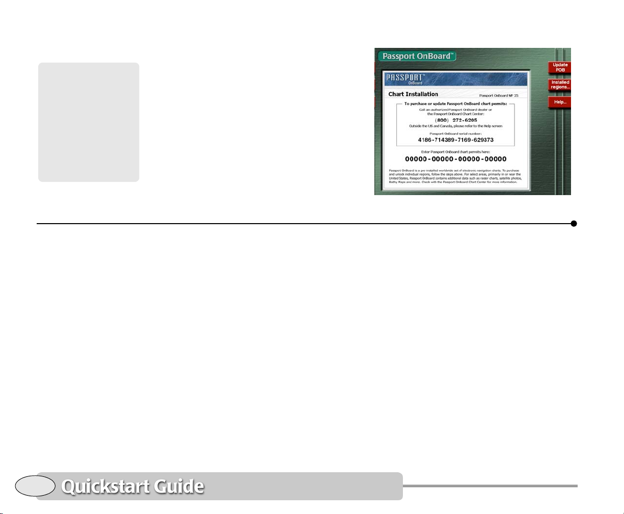
Displaying available charts
Press the STAR key repeatedly until the
Passport OnBoard screen appears. On this
screen, you can see the activated chart
regions and enter additional chart permits.
Displaying the chart screen
After the 972 completes its start-up
sequence, press the
acknowledge the warning message and
display the
Chart screen.
CHART function key to
Chart Setup/status screen
You’ll see your present position represented by a red vessel symbol in the center
of the chart. If you’re not receiving GPS
signals, you can use Demo Mode, as
described on page 19.
14
Displaying the chart screen
Northstar 972
Page 19
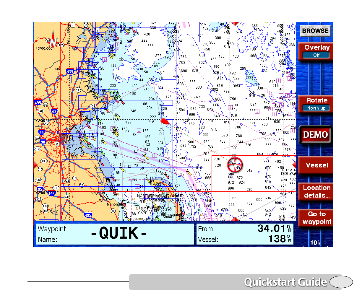
Chart screen
Quickstart Guide Revision B
Displaying the chart screen
15
Page 20
The 972’s Chart screen displays your
vessel’s present position (or any position
you designate with the cursor pad) in
relation to land masses, nav aids, and any
waypoints and routes you have entered. As
you navigate, your vessel remains
stationary on the
Chart screen, and the
chart moves underneath your vessel.
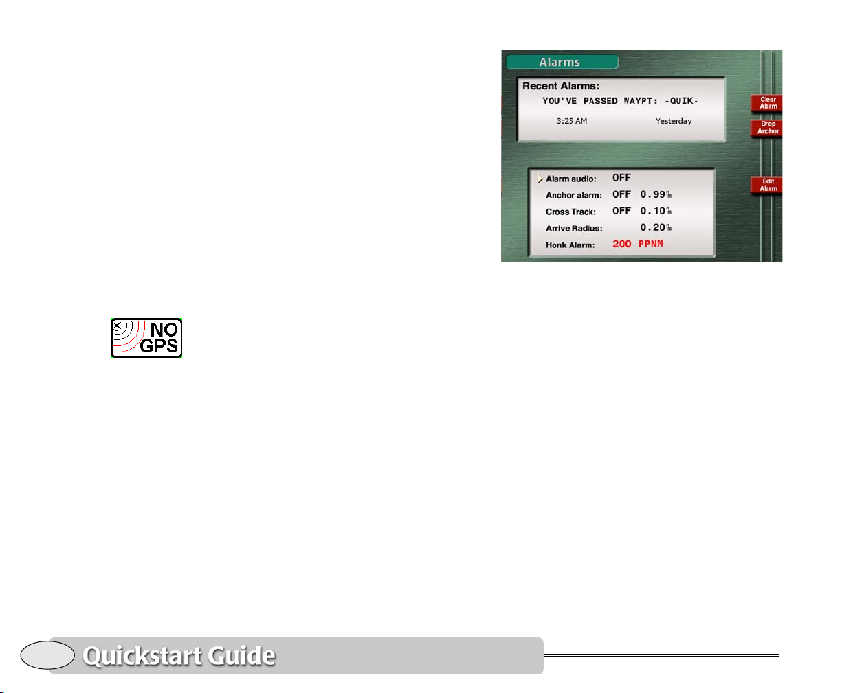
Clearing a GPS or WAAS alarm
If the 972 isn’t able to obtain a position
from GPS within three minutes, you’ll see a
flashing NO GPS alarm icon on the right
side of the screen. This means the 972 has
an alarm message that needs your
acknowledgement: Press the
key to display the Alarms screen.
The alarm message NO GPS POSITION
FIX
is shown in the Recent Alarms box.
This message advises you that the 972 is
still in the process of acquiring satellite
information necessary for displaying a
position fix.
The word NEW in the upper right corner of
the screen tells you this message hasn’t yet
been acknowledged. To acknowledge this
or any message alarm, press the Clear
alarm menu key. As soon as the 972
acquires its signals, you’ll be ready to go.
STAR function
Alarms screen
For details about alarms, see Alarms,
starting on page 132.
Using the chart
Your vessel is normally shown in the
center of the chart screen. If your vessel is
moving, the symbol will point in the direction of your Course Over Ground (COG). (If
your vessel isn’t moving, the 972 can’t
determine your COG, so the direction of
the vessel symbol won’t mean anything.)
To zoom in and see more details about
your position, press the
out (more area and less detail), press
IN key. To zoom
OUT.
16
Displaying the chart screen
Northstar 972
Page 21
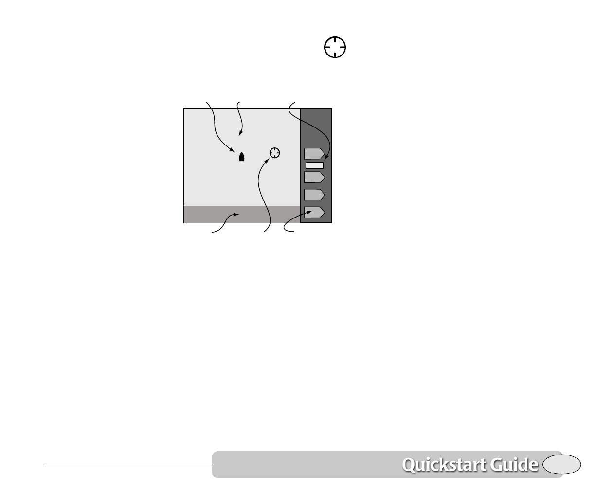
Press the cursor pad to display the
red cursor and designate waypoints
or move the chart to a different
area. Press Vessel to recenter the chart on
your vessel.
Vessel GPS Status
Info bar Menu keysCursor
Chart area
WAAS
Chart screen
• display any available overlays, such as
radar
• rotate the chart to north-up, course-up,
leg-up or heading-up (heading-up
requires an optional heading sensor)
• return from “Browse” mode (cursor
on-screen) to “Vessel” mode (vessel
centered)
• show detailed information about the
displayed chart
• display additional position information
in the
Info bar at the bottom of the
screen
• go to a waypoint, nav aid, or unmarked
point you select on the chart screen by
pressing the cursor pad
Quickstart Guide Revision B
The GPS status is shown on the right side
of the screen:
•GPS — navigating with normal GPS
signals
• WAAS — navigation enhanced with
high-accuracy WAAS signals.
•DEMO — running in simulation mode
Chart plotter functions
The menu keys at the right of the chart
screen perform the following navigation
functions (not all keys are shown all the
time):
Displaying the chart screen
Displaying other information
On the Chart screen, you can display your
current route, track history, waypoints and
avoidance points, a lat/lon grid, a radar
overlay, or other chart details. See Setting
up the chart screen, on page 33.
17
Page 22

Chart options
3D chart screens
Once on the Chart screen, Press and hold
the
CHART key to display options for the
Chart screen. See page 33 for the other
options.
The Northstar 972 can also display
three-dimensional images of the ocean
bottom and land areas. Press the
display these images.
Use the cursor pad to position the camera
viewpoint.
A red line drops from the vessel to the
seabed to show the water depth visually.
Menu keys:
• Overlay — applies a vector-based chart
to the 3D image (this operation may
take quite a bit of time the first time a
chart is accessed)
3D key to
Press Chart Detail to select the items to be
displayed on the chart screen.
• Browse — allows the viewpoint to be
moved by using the cursor pad
• Bottom Lock — Locks the camera to the
seabed directly under the vessel,
instead of the vessel itself
• Camera up — in Browse mode, moves
the camera viewpoint higher
• Camera down — in Browse mode, moves
the camera viewpoint lower
• More info — steps through the available
info bars at the bottom of the screen
•
Alarms
18
The Northstar 972 alerts you to conditions
that may require attention. Some alerts are
strictly informative, such as nearing a
waypoint, and some warn of conditions
Chart options
such as loss of navigation signals. The unit
alerts you with a beeping sound and a
flashing symbol at the right edge of the
screen. Many alarms automatically clear
Northstar 972
Page 23
themselves after a few seconds. Others
remain flashing until you press a key on
the
Using demo mode
Alarm screen or until the condition
clears. See Alarms, starting on page 132 for
a listing of all alarms and the meaning of
each.
You can use demo mode to simulate a
stationary position, or simulate navigating
to a location you select on the
Demo mode is useful for training, and
could be used for dead reckoning in the
event that GPS signals should ever fail.
To access the demo control screen, display
the
Chart screen and press and hold CHART
to display the chart options. Then press
Demo control.
To place your vessel at a simulated
position and enter demo mode, press the
cursor pad to move the cursor to the
desired position on the chart. Zoom out if
you need to see more area. Press Demo
Position and then
symbol will now be stationary at this
position.
ENTER. Your vessel
Chart screen.
Displaying numeric data on the chart screen
To simulate motion from this point to
another location, press the cursor pad to
move the cursor to the destination, then
press the Demo COG/SOG key. To change
the vessel’s speed from the standard 10
knots, use the keypad to enter the new
speed. Finally, press
to the demo cursor location.
To view the
mode, press Return twice.
To leave demo mode, go back to the Demo
control
screen as described above, and press
Exit Demo.
Chart screen while in demo
The word Demo always appears on the
right side of the Chart screen when you’re in
demo mode.
This key returns you directly to the active
Chart screen.
ENTER to start moving
Quickstart Guide Revision B
To display numeric information directly on
the chart screen, press the More Info menu
key to display an “info bar” at the bottom
Using demo mode
of the screen. (If the More Info key is not
visible, press Vessel to restore it.)
19
Page 24
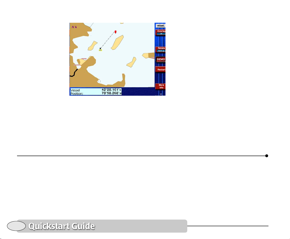
Vessel lat/lon displayed on chart screen
Each additional press of the More Info key
shows the following information:
• your vessel’s present
Speed-Over-Ground (SOG),
Course-Over-Ground (COG), heading
(HDG) (if a heading sensor is connected)
• your vessel’s distance (Dist) and bearing
(Brg) to the current waypoint, if any,
along with a cross-track indicator
• your vessel’s position in lat/lon (or TDs,
if you’ve enabled loran)
• tide and current information at the
nearest tide station
Displaying numeric data on the position screen
To display your position, speed, course,
and time with large, easily read digits, press
POSITION. The GPS Position screen shows
the following information:
• your vessel’s position in lat/lon (or
Phantom loran TDs, if enabled)
• your vessel’s present SOG and COG
20
Displaying numeric data on the position screen
• current time, day, and date
• geodetic datum (for details, see
Choosing a geodetic datum, starting on
page 149)
Press
POSITION a second time to see
Phantom loran TDs See Using Phantom
Loran, on page 49.
Northstar 972
Page 25
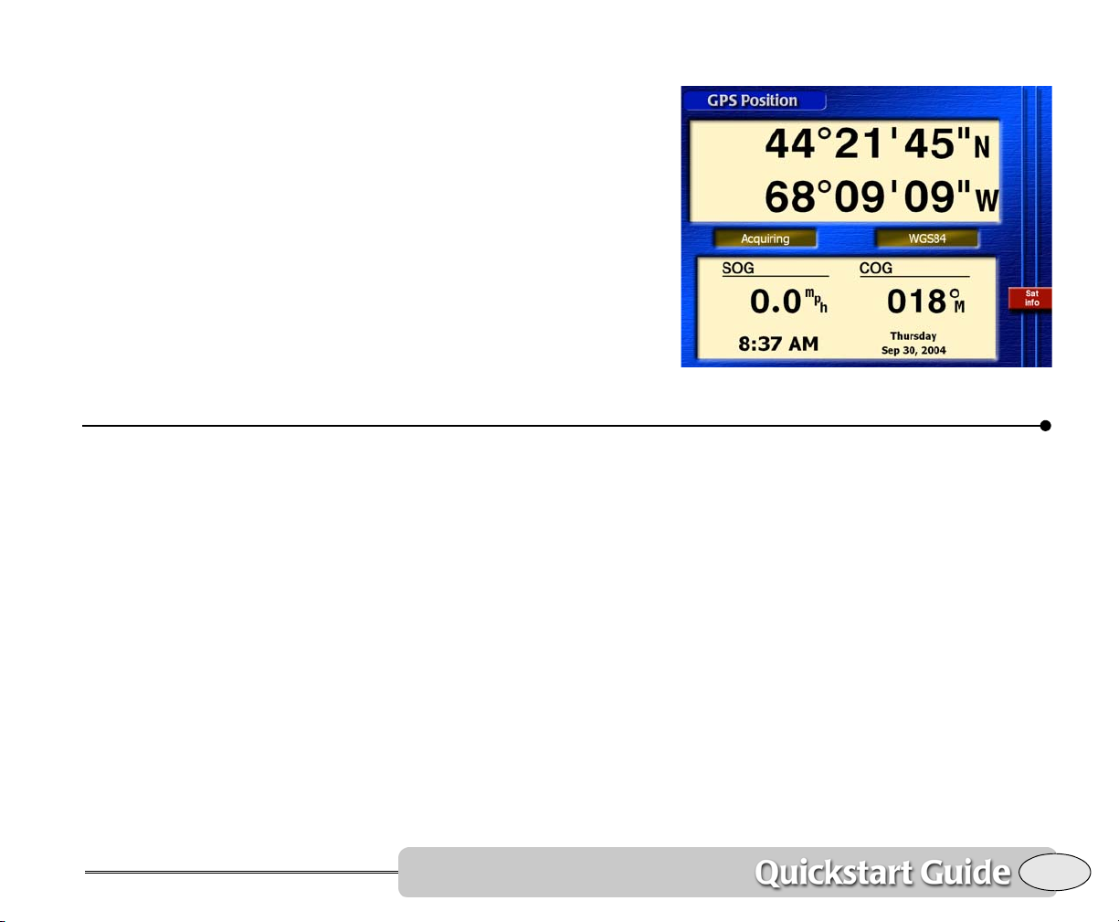
Press and hold POSITION to display options
for this screen (see Position screen options,
on page 47).
For details about using this screen, see
Position coordinates, starting on page 45.
Going immediately to a quick waypoint
GPS position screen
Quickstart Guide Revision B
The Northstar 972 can guide you directly
to any point on the chart screen that you
designate. “Point-and-shoot” navigation, as
it is called, is often the easiest way to go to
a waypoint or a series of waypoints: Just
select the points right on the chart and go
to them, one after another. This technique
provides the most flexibility in deciding
where you want to travel. Simply move the
cursor wherever you want, press a key, and
you’re navigating.
1. Press the CHART key to display the Chart
screen.
2. Press the cursor pad to move the cursor to
the desired spot on the chart.
Going immediately to a quick waypoint
3. Press Go to cursor.
4. Press ENTER.
The 972 displays a track line to the new
waypoint named
directly to this point.
-QUIK-, and guides you
21
Page 26

Radar
Watch your progress on the chart screen,
or press
straight-line course to the waypoint (see
Steering to a waypoint, starting on page 54).
That’s all you have to do to use the 972 in
its simplest form. To learn more about
navigating to waypoints, See Navigating to
Waypoints, starting on page 51.
Navigating
STEER to stay accurately on the
22
Using the optional Northstar radar you can
determine where other boats or ships, navigational markers, land masses, flocks of
birds, and other objects are located in
relation to your vessel, and you can track
their movements.
The radar won’t be operational until you
turn on the radar transmitter. See
Displaying radar, starting on page 87.
If a Northstar radar unit is interfaced to the
972, press
Press Adjust Radar… to make operating
adjustments to the radar system as
RADAR to see the radar image.
Radar
described in Using the Adjustment keys,
starting on page 91.
Press Adjust Markers… to set the radar’s
Electronic Bearing Lines, Range Rings, etc.
as described in Using the Markers keys,
starting on page 94.
On the
overlay to superimpose the radar image on
the chart screen. More information on
radar starts on page 85. You can also designate and track MARPA targets with the
Northstar 972.
Chart screen, you can press Radar
Northstar 972
Page 27
For information on installing radar and
making it operational, see the Northstar
The echo sounder
Radar Installation Manual (part number
GMEKRADIM).
Split function
If your 972 is equipped with Northstar’s
optional echo sounder, press
display the full
Echo Sounder screen.
SOUNDER to
The SPLIT key
You can split the screen to display several
navigation functions on the screen at the
same time. For example, you could display
the chart, sounder and radar images simultaneously, or even two chart screens.
A chart screen is always shown on the left
side, and you can choose one or two other
functions to be displayed on the right side.
Press the
two or three sections, each with a different
function displayed. Press
time to configure the combination of functions to be displayed.
For two simultaneous functions, just press
Right to step through the options.
SPLIT key to split the screen into
SPLIT a second
For the simplest operation, press Auto, and
select the desired transducer frequency
and zoom modes. More information about
sounder setup and operation starts on
page 103.
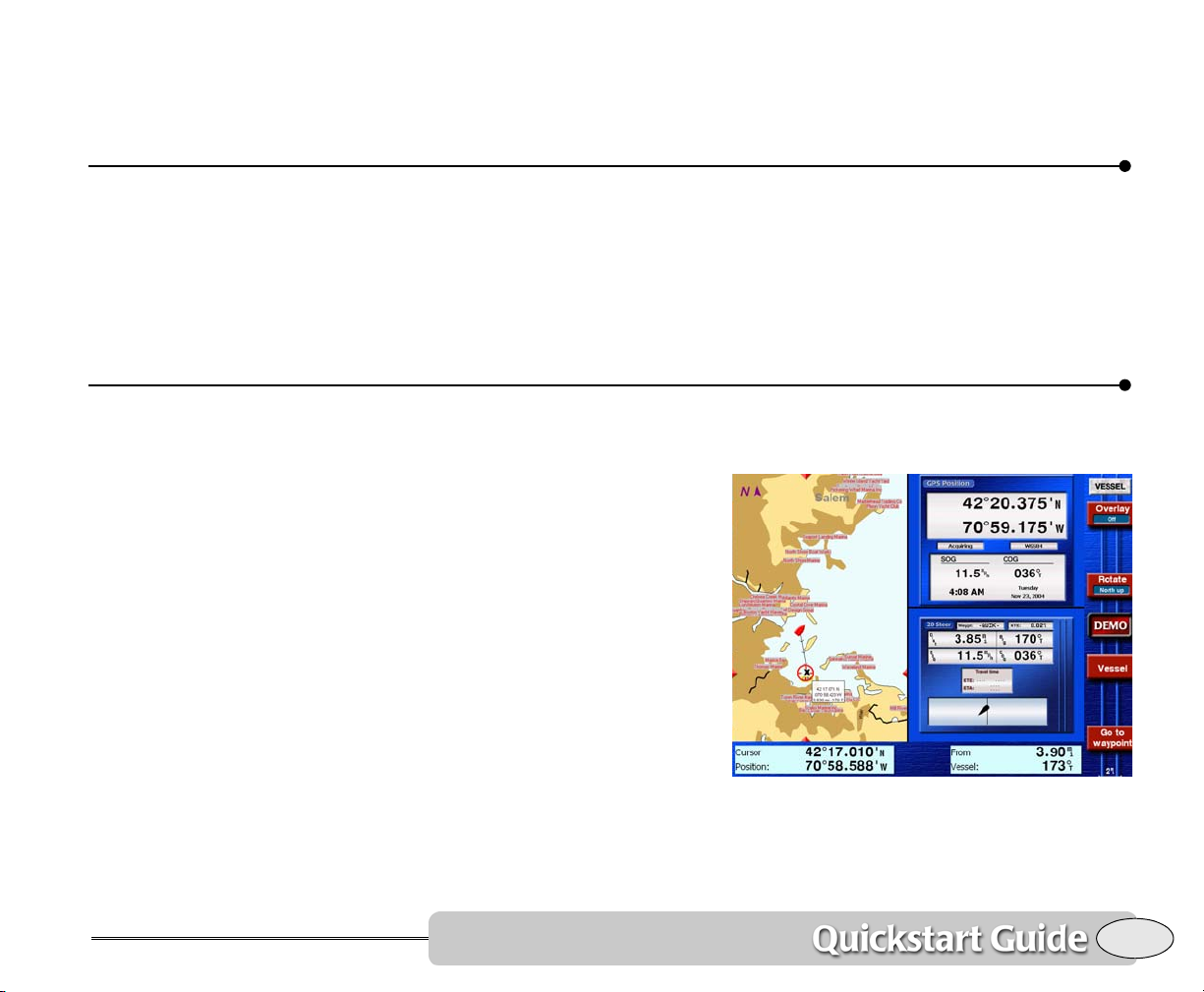
Split screen with Chart, Position and Steer
For three simultaneous functions, press
3-way split. Then press Top to step through
Quickstart Guide Revision B
The echo sounder
23
Page 28
the available screens for the top right function. Press Bottom to step through the
same choices for the bottom right function.
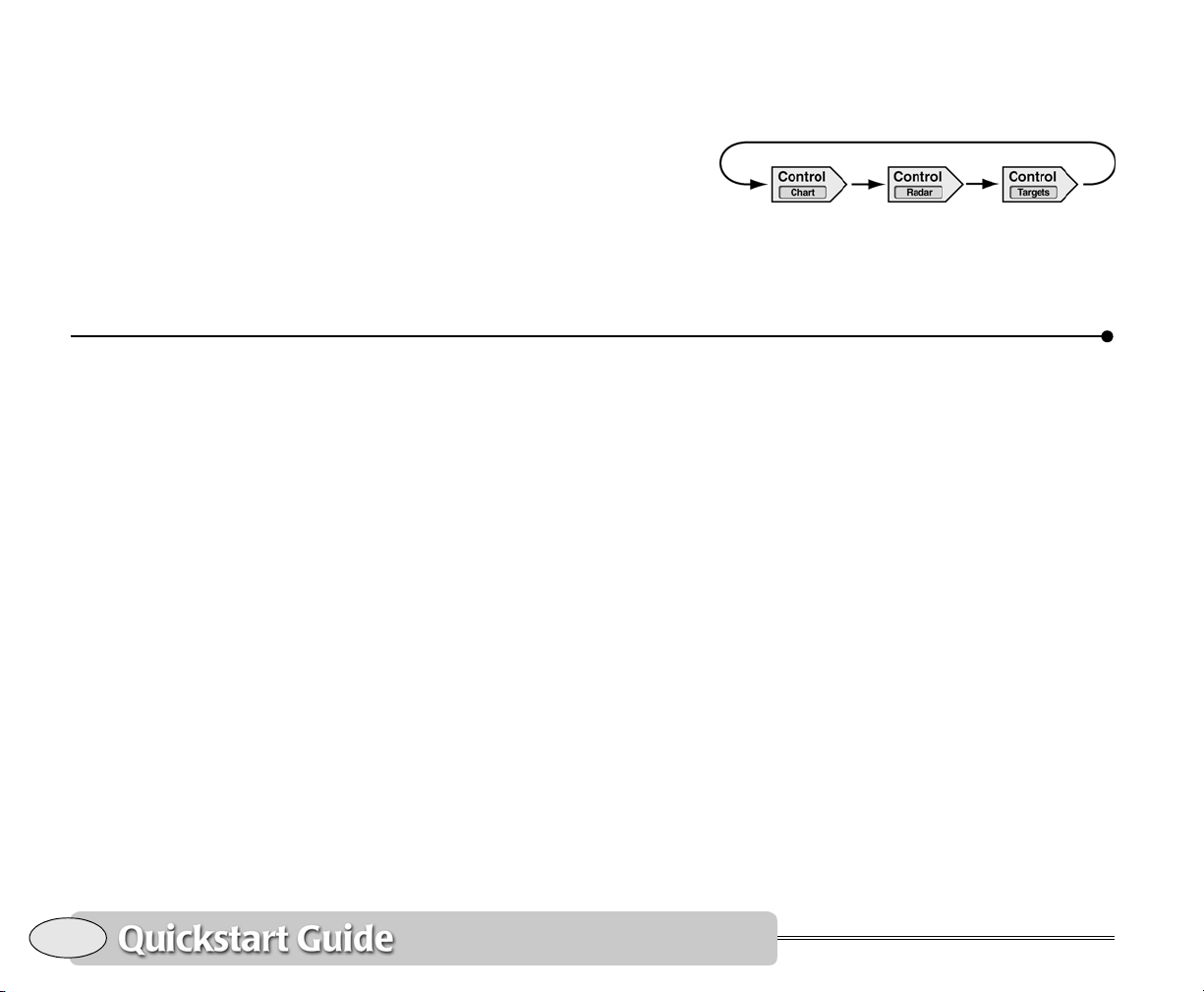
The Control key
When the screen is split to show more than
one function, you can press Control to
The STAR key: alarms, TideTrack and setup
select which of the displayed functions is
controlled by the menu keys. For example:
The Control key is also available when the
radar overlay is in use.
24
Using the alarms
The 972 has several alarms that automatically alert you to certain situations. For
example, the 972 lets you know when
you’re approaching a waypoint by
sounding a beep and flashing an alarm
icon on the screen. The icon explains the
reason for the alarm. Most of the common
alarms automatically cancel themselves
after ten seconds or after the condition
ends. For details, see Alarms, starting on
page 132.
Using TideTrack™
Press the STAR key repeatedly until you see
the 972’s Tide Track screen, a 24-hour tide
graph for any of over 3,000 NOAA tide
stations covering the entire U.S. coastline,
The STAR key: alarms, TideTrack and setup
including Alaska and Hawaii, plus much of
the eastern and western Canadian coastline. You can display tides for today or any
other date. For details about TideTrack, see
TideTrack™, starting on page 137.
Press
STAR again to display currents in the
same manner.
Tide and current data are available for
chart regions that have been activated for
use.
Setup functions
Additional presses of the STAR key access
the 972’s various setup and customization
functions. These functions are described
beginning on page 146.
Northstar 972
Page 29
SAVE and Man Overboard (MOB)
Pressing SAVE/MOB always saves your
present position as a waypoint.
Saving waypoints
Press SAVE briefly to save a waypoint. The
new waypoint is given a name such as
-S002-, where the letter S indicates a saved
waypoint, and the three-digit number
increases by one every time you save a
waypoint.
You can limit the number of saved
waypoints that will be stored. Use the
Saved waypoints
Options
saved waypoints, on page 148).
When the three-digit number reaches the
specified maximum, it wraps back to
and overwrites the older waypoint that has
the same number.
Any saved waypoints that you want to
keep or use in a route should be renamed
before they are overwritten (see Editing
waypoints, starting on page 69).
menu (see The maximum number of
function in the Navigation
Max
001
Saving routes
You can set the 972 to automatically save a
sequence of waypoints as a route. Each
time you press
recorded as an additional waypoint in the
route. See Saving a route as you travel,
starting on page 74 for details.
SAVE, your position will be
Man Overboard
Press and hold the SAVE/MOB for at least
four seconds (until you see the “Man Overboard” window) to save your position as a
waypoint named
ately and automatically does the following:
• switches to a zoomed-in chart screen
showing your vessel and the MOB
waypoint
• enables the wake line
• switches to vessel mode
• starts navigating to the MOB point
You can use any of the unit’s functions to
return to the location of the waypoint. The
972 never shows the “Arrive” indication —
it continues guiding you to the MOB
waypoint until you instruct it otherwise.
When you’re finished using the MOB function, just continue using the 972 in
whatever way you wish.
–MOB–. The 972 immedi-
Quickstart Guide Revision B
SAVE and Man Overboard (MOB)
25
Page 30
26
SAVE and Man Overboard (MOB)
Northstar 972
Page 31
Reference section 1
Using the Chart Screen
Using electronic charts . . . . . . . . . . . . . . . . . . . . . . . . . . . . . . . 28
Zooming in and out . . . . . . . . . . . . . . . . . . . . . . . . . . . . . . . . 28
Using the cursor on the chart screen . . . . . . . . . . . . . . . . . 29
Comparing vessel and browse modes . . . . . . . . . . . . . . . . 29
Rotating the chart . . . . . . . . . . . . . . . . . . . . . . . . . . . . . . . . . 31
Setting up the chart screen . . . . . . . . . . . . . . . . . . . . . . . . . 33
Using the course predictor line . . . . . . . . . . . . . . . . . . . . . . . . 38
Using the distance and bearing calculator . . . . . . . . . . . . . 38
This section explains the electronic chart, the two chart modes (Vessel and Browse), the
various chart symbols and their meanings, and how to set up the chart display to operate
the way you want it to be.
Reference Manual Revision B
27
Page 32
Using electronic charts
Electronic charts contain most of the infor-
CAUTION!
Nav aids have been
converted from official
paper charts into the
electronic format on
your screen, and therefore aren’t necessarily
as accurate as the
paper charts. In some
areas, only the most
important nav aids may
be shown.
mation from the original paper charts. You
can select which categories of data are
displayed to simplify the screen. When
used with caution, electronic charts open
up a world of navigational accuracy and
simplicity.
Chart boundaries
The 972 displays the boundary line of each
chart on the
these lines off if you prefer (see Choosing
vector chart details, starting on page 35).
If you move from a highly detailed chart to
a less detailed one, you may see a sudden
change in the detail shown on the screen,
just as if you had changed from one
detailed paper chart to a less detailed one.
The displayed boundary lines may help
Chart screen. You can turn
indicate when this change in detail is going
to happen.
Lights and buoys
The nav aids on the Chart screen represent
a variety of standard “aids to navigation”
used on coastal and inland waterways
throughout the United States. Most of
these aids are buoys, lights, lighthouses,
and daybeacons, which typically are maintained by the U.S. Coast Guard. Nav aids
warn you of hidden dangers, such as
underwater hazards, and to help you safely
navigate specific waterways and channels.
On a vector chart, when you move the
cursor over a nav aid, with popups are
turned on, the 972 displays a description in
the popup rectangle near the nav aid,
along with the distance and bearing from
your vessel to the nav aid.
Zooming in and out
To get a closer look at the chart area
around your vessel or around the cursor,
press the
area, press
IN or OUT approximately halves or doubles
the chart scale.
28
Reference section 1 — Using the Chart Screen
Using electronic charts
IN key to zoom in. To see a wider
OUT to zoom out. Each press of
NOTE:
Whenever the radar overlay is turned on
and “Auto Range” is turned on, the scales of
the chart and the radar are locked together
so that the images will line up. If you change
the scale of one, the scale of the other
changes automatically.
Northstar 972
Page 33
Using the cursor on the chart screen
Pressing the cursor pad displays the
red cursor symbol on the
Chart
screen. Further pressing of the
cursor pad moves the cursor across the
screen.
If you have trouble finding the cursor in a
busy part of the Chart screen, just look at
the edges of the screen for the red cursor
pointers: They line up with the cursor.
When you press the cursor pad, the 972
goes into browse mode, described on
page 29.
If you move the cursor on top of a
waypoint or navaid, you will select that
point. Information about the selected point
appears in the popup rectangle.
After pressing the cursor pad to move the
cursor to a point on the chart, you can
Comparing vessel and browse modes
press Go to cursor and
ENTER to start navi-
gating to the designated cursor location.
If you placed the cursor on a waypoint, this
menu key would read Go to waypt.
You can use the cursor to:
• select a nav aid or waypoint, to:
> show its name, lat/lon, and distance
and bearing
> navigate to it
> add it to a route
•
designate a point on the chart, to:
> show its lat/lon
> navigate to it
> add it to a route
> store as a waypoint
•
select a leg of a route to follow or edit
• view a new area of the chart by moving
the cursor to the edge of the screen
Reference Manual Revision B
The 972 offers two display modes:
• vessel (your vessel is centered on the
screen)
• browse (a cursor is displayed, which
you can move to designate points or
explore other areas of the chart)
Reference section 1 — Using the Chart Screen
Using the cursor on the chart screen
29
Page 34
When your vessel’s position
moves to the edge of a chart,
its icon may move from the
center of the screen.
To switch from vessel mode to browse
mode, press the cursor pad. To switch back
to vessel mode, press the Vessel menu key.
Vessel mode
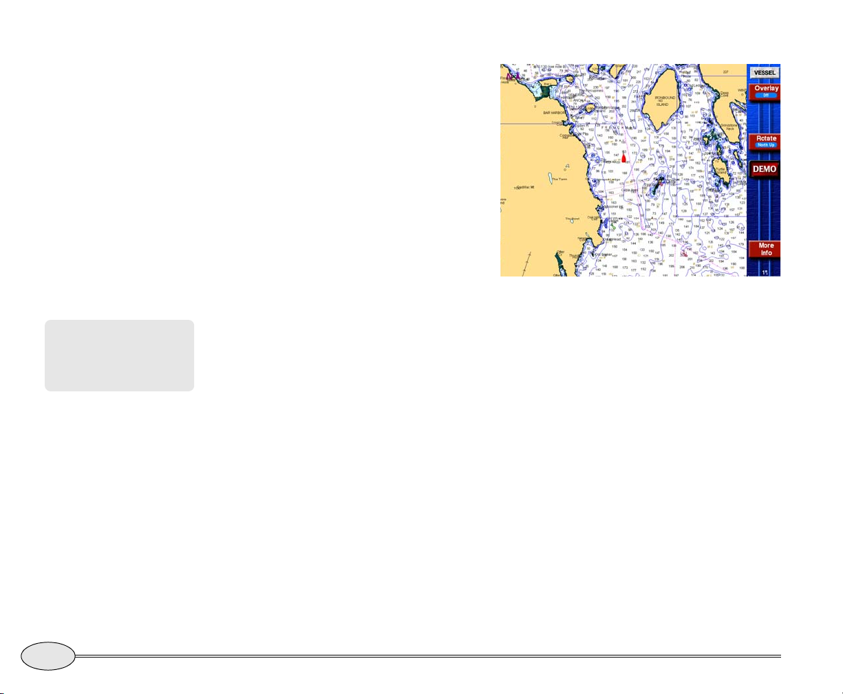
The word VESSEL in the upper right
corner of the screen means you are
currently using Vessel mode.
Vessel mode is the primary screen for navigating — the chart moves automatically
under your vessel, which remains
stationary on the screen. It provides a
continuous view of your surroundings.
Press More info to display your position
coordinates in the info bar at the bottom of
the screen. You can also display your SOG
and COG, or distance and bearing to the
current waypoint (if any), or the nearest
tide and current station.
Vessel mode
Browse mode
The word BROWSE in the upper right
corner of the screen means you are
currently using Browse mode.
30
Reference section 1 — Using the Chart Screen
Comparing vessel and browse modes
Northstar 972
Page 35
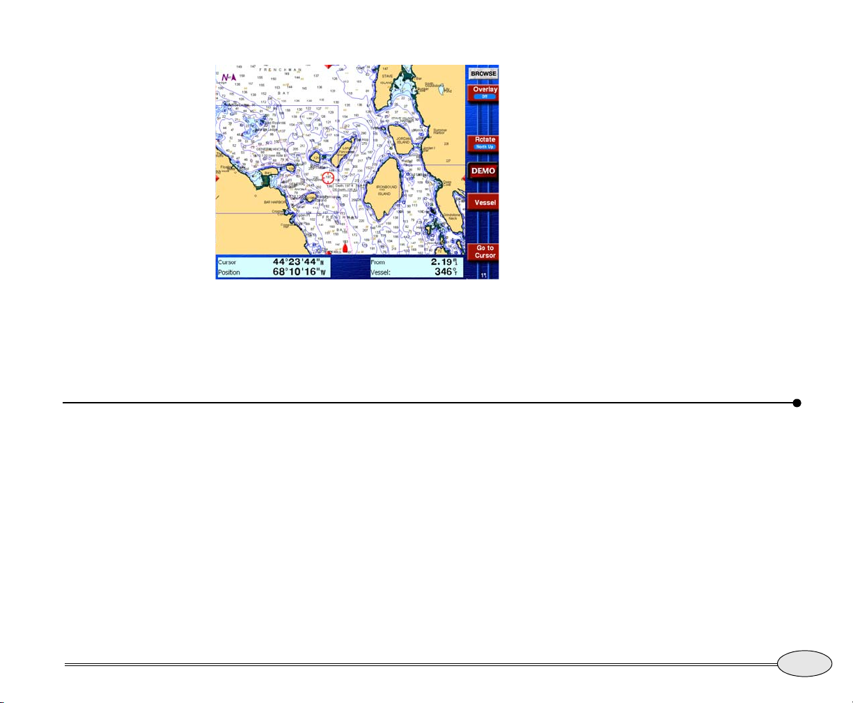
In browse mode, you can use the cursor to
look at other areas of the chart, and designate points you want to navigate to.
Rotating the chart
The info bar at the bottom of the screen
displays the position coordinates of the
cursor, and the distance and bearing from
your vessel to the cursor.
Browse mode
Reference Manual Revision B
Press the Rotate key to change the angle of
the charts displayed on the
Chart screen. As
long as you’re in vessel mode, you can
rotate the chart to any of the following
angles:
• North-up – No rotation.
• Course-up – As your vessel changes its
direction of travel, the chart rotates to
keep your COG straight up on the
screen. Course-up represents your true
COG as determined by the GPS
receiver.
The 972 ignores any course changes if your
speed is under half a knot.
The chart reacts very slowly to turns of less
than 5°, to avoid annoying small rotations.
Your COG is often different from your
vessel’s heading, so what you see straight
Reference section 1 — Using the Chart Screen
Rotating the chart
31
Page 36
ahead on the horizon may be different from
what’s displayed on the screen.
• Heading-up – This rotation is available
only if you have a heading sensor
installed and enabled. The chart rotates
as you travel to keep your heading
straight up on the screen. When you
select heading-up, the heading line on
the radar image points straight
upwards. The heading line allows you
to compare the radar image or the chart
with the view in front of the vessel.
• Leg-up – The direction of the current
leg to a waypoint points straight
upwards on the screen. The 972 rotates
the chart whenever you start
navigating on a new leg, even if you
haven’t turned the vessel yet.
course, you won’t see the chart rotate
to the new direction until you return to
vessel mode by pressing the Vessel key.
Only in vessel mode will the chart
rotate to follow your course angle.
• Leg-up: If you’re displaying charts in
browse mode as leg-up and the 972
switches to a new leg, the chart will
immediately rotate to the direction of
that new leg.
NOTES:
The edges of other charts in the 972’s
built-in world chart folio are shown, in
addition to those installed. These edges are
shown as black or red dashed lines.
The lat/lon grid is labelled only when the
chart is north-up.
32
Using chart rotation in browse mode
Chart rotation is most useful in vessel
mode. In browse mode, rotation is stabilized to keep the chart and cursor from
jumping while you’re browsing around on
the chart.
• Course-up or Heading-up: Suppose
you’re displaying the charts as
course-up or heading-up and you press
the cursor pad to use browse mode.
While in browse mode, the chart
rotation freezes. If your vessel changes
Reference section 1 — Using the Chart Screen
Rotating the chart
How rotating affects the chart and radar
The rotation of the chart and the rotation
of the radar image interact under certain
circumstances, as described below. Assume
that the chart and radar are both north-up
at the start:
Northstar 972
Page 37
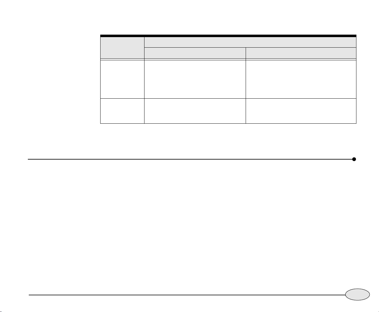
If the Chart
screen’s in…
And the radar image is…
Overlaid on the chart Not overlaid
Browse mode The chart can’t rotate in Browse
Vessel mode Chart and radar both rotate together.
Setting up the chart screen
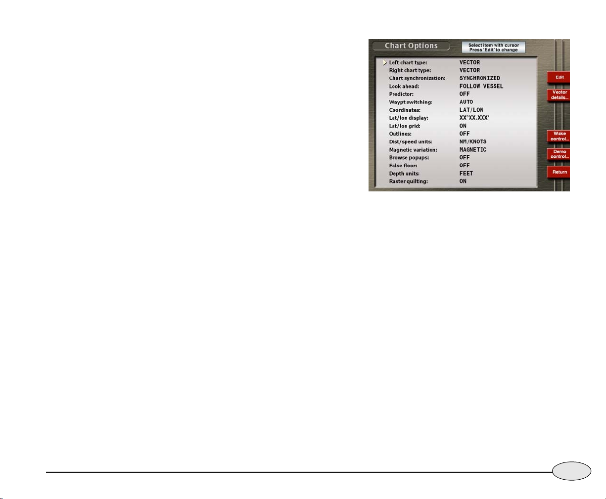
The Chart Options screen lets you select the
details on the
track control, and control Demo Mode to
simulate navigation and radar.
Press the
screen, then press and hold the
to display the
The following options can be set directly
from this screen. All units settings apply
system-wide.
Chart screen, adjust the 972’s
CHART key to display the Chart
Chart Options screen.
mode. If you change the
Radar, the chart’s mode
to
automatically switches to vessel mode
and rotates as described below).
If you change the rotation of one, the
other automatically changes to match.
Control key
Left chart type
On a split screen with two charts displayed,
choose whether the left chart is raster,
vector, blend or photo.
CHART key
Right chart type
On a split screen with two charts displayed,
choose whether the right chart is raster,
vector, blend or photo.
The chart can’t rotate, but the radar can
rotate. Chart and radar can have different
rotations.
Chart and radar can both rotate. Chart
and radar can have different rotations.
Reference Manual Revision B
Reference section 1 — Using the Chart Screen
Setting up the chart screen
33
Page 38
Chart synchronization
Lat/lon grid
On a split screen with two charts displayed,
choose whether or not the two charts are
synchronized so that both charts always
pan together.
Look Ahead
Follow vessel — the vessel is centered in
the screen
Look ahead — shows a larger area ahead of
the vessel
Predictor
Off, 1, 2, 3, 5, 10, 15, 30 minutes. Controls
the length of the course predictor line.
Waypoint Switching
Switch to the next waypoint automatically
upon arrival, or require manual switching.
Coordinates
Lat/lon or Phantom Loran TDs
The ON setting displays lat/lon lines on the
Chart screen. Turn lat/lon lines off when
these lines add excessive clutter to your
screen.
Outlines
Displays the edges of the Passport chart
regions. Off, Installed charts, Passport
regions, Both.
Dist/Speed Units
Nautical miles and knots, miles and miles
per hour, or kilometers and kilometers per
hour
Magnetic variation
True or magnetic
Browse popups
On or Off. Displays information next to the
cursor about depths, navaids, obstructions,
etc.
34
Lat/lon display
Degrees, minutes and seconds or degrees,
minutes and thousandths of minutes.
Reference section 1 — Using the Chart Screen
Setting up the chart screen
False floor
To improve the appearance of
below-the-surface colors, this function
Northstar 972
Page 39
compresses the range so that the full range
of colors is displayed between the surface
and the false floor. Choose Off, 100ft,
250ft, 500ft, 1000ft, 2000ft, 4000ft. (This
option applies only when the Shaded relief
is turned on).
Depth units
Feet, meters or fathoms.
Raster quilting
Choose whether or not raster charts are
quilted to provide a seamless large area of
coverage. You may see the edges of the
chart coverage area when using this
option.
Chart Options screen
Choosing vector chart details
To set up the chart details, press the Vector
details menu key on the
screen.
Chart Options
Reference Manual Revision B
To change any option, press the
to move the cursor triangle to the desired
item, then press the On/Off menu key to
change the item. An item that is turned off
is shown with two dashes.
Reference section 1 — Using the Chart Screen
Setting up the chart screen
cursor pad
35
Page 40
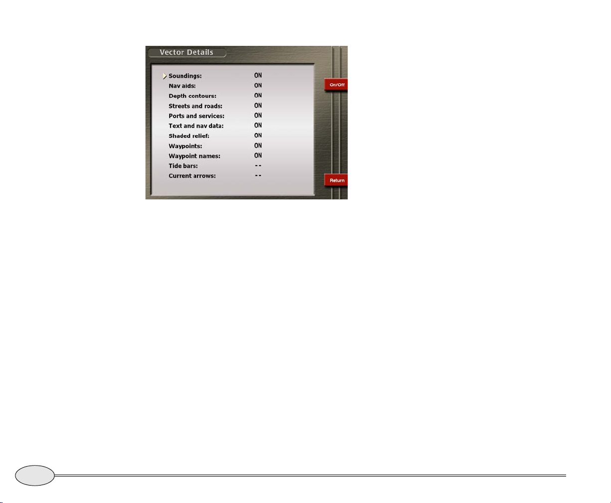
Vector Details screen
The following items are displayed:
Soundings
Display numerical depth soundings on the
chart
Text and navdata
Streets and Roads
Display streets and roads on land masses
Shaded Relief
The ON setting displays water depths as a
shaded range of colors. This gives a 3D-like
appearance to the chart
Way poin ts
The ON setting displays your waypoints on
the
Chart screen, and the OFF setting turns
them off, with the exception of waypoints
on a displayed route.
Waypoint names
The ON setting displays the name of each
waypoint below its symbol. The OFF
setting displays just the symbol itself.
36
Navaids
Display navaids on the chart
Depth contours
Display depth contour lines
Reference section 1 — Using the Chart Screen
Setting up the chart screen
Tide Bars
Current Arrows
Changing the wake display
The 972 displays your wake as a line indicating the path you’ve recently traveled.
(The wake is sometimes referred to as a
track line). You can choose how often to
Northstar 972
Page 41
store a position fix as a point in your wake
and the length of the wake in minutes.
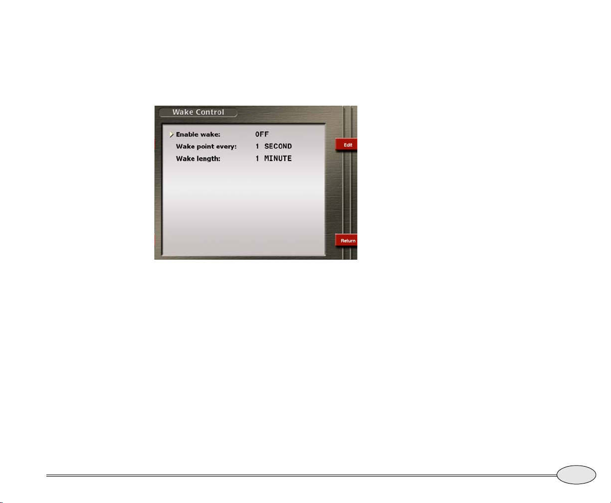
To show the
Wake control on the
Wake Display screen, press
Chart Options screen.
Wake Control screen
Wake point every
You can choose among the following
options for point display, and the corresponding track length:
• every 1 second
• every 2 seconds
• every 4 seconds
• every 8 seconds
• every 20 seconds
• every 40 seconds
• every 1 minute
• every 2 minutes
Wake length
Set the length of the displayed wake to 1,
2, 5, 10, 20, 30, 60 or 120 minutes.
Reference Manual Revision B
To change any of these options, use the
cursor pad to move the arrow to the field
you want to change, then press Edit. Press
the cursor pad to display the option you
want. Press
ENTER to lock in the selection.
Enable Wake
Set to On to display the wake.
Set to
Off to turn it off.
Press Return twice to return to the
Chart
screen.
Demo control
See Using demo mode, on page 19 to use
Demo mode for simulating vessel motion
in any area of the world.
Reference section 1 — Using the Chart Screen
Setting up the chart screen
37
Page 42
Using the course predictor line
The chart, 3D steer, and radar screens also
display a course predictor line that indicates where your vessel will be in a few
minutes if you maintain your current
course and speed. The predictor line
extends out from your vessel in the direction of your Course Over Ground. Its
length is determined by your speed and
the number of minutes you specify on the
Chart Options screen. You can also turn the
line off.
To use the predictor line, simply select the
number of minutes you prefer the line to
represent as follows:
Using the distance and bearing calculator
You can quickly check the distance and
bearing between any two points on the
Chart screen. You can also use this function
to make new waypoints that you define by
their distance and bearing from another
point.
1. Press WAYPTS/ROUTES.
2. Press
Distance and Bearing.
The 972 displays a symbol at the cursor
position.
1. While on the Chart screen, press and hold the
CHART key to display the Chart Options
screen.
2. Select
3. Press
4. Use the cursor pad to display the desired line
5. Press ENTER.
Predictor using the cursor pad.
Edit.
length (in minutes).
Then, just watch the predictor line on the
chart or 3D steer screen to determine
where your current course will take you.
3. Press the cursor pad to move the cursor to
the desired location.
The distance and bearing from your position to the cursor is displayed in the info
bar.
4. To measure the distance and bearing from the
cursor to another point, press
“X,” or starting point, is displayed at
A new
that location. As you move the cursor, the
distance and bearing from the
the cursor’s position are displayed in the
Set new “X.”
“X” point to
info bar.
38
Reference section 1 — Using the Chart Screen
Using the course predictor line
Northstar 972
Page 43
If you want to make a waypoint at the
cursor location, press Add waypoint, then
enter its name, symbol, and any description on the
ENTER to save it.
New Waypoint screen. Press
Reference Manual Revision B
Reference section 1 — Using the Chart Screen
Using the distance and bearing calculator
39
Page 44
40
Reference section 1 — Using the Chart Screen
Using the distance and bearing calculator
Northstar 972
Page 45
Reference section 2
3D maps
Introduction to 3D images . . . . . . . . . . . . . . . . . . . . . . . . . . . . 42
Configuring the screen . . . . . . . . . . . . . . . . . . . . . . . . . . . . . . . 43
Flying around the vessel. . . . . . . . . . . . . . . . . . . . . . . . . . . . . . 44
The 3D key displays your position on a three-dimensional view of the ocean floor or land.
Marine charts, topo maps or photos can be overlaid on the image.
Reference Manual Revision B
41
Page 46
Introduction to 3D images
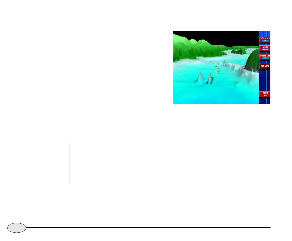
Using the 972’s 3D screens, you can view
the ocean floor and land information as a
three-dimensional image. You can see
favorite fishing spots, harbor entrances,
and even navigation channels in a full 3D
view, both above and below the water
surface.
You can use the cursor pad to “fly” around
your vessel to observe your surroundings
from a different position.
Note that the first time an area is accessed
for 3D display, it may take some time to
read the data from the disk drive and
process it for display. Blending modes,
especially Photo Blending, require a long
processing time to prepare an image for
display. Once the data is processed, this
display updates quickly.
3D screen
Overlay
42
While every effort has been made to provide
the best elevation data possible, errors in the
source material, data processing and the 3D
presentation may occur. The prudent mariner
will always have official navigation charts for
comparison and as their primary means of
navigation.
Reference section 2 — 3D maps
Introduction to 3D images
Turn On or Off the overlay selected (may be
vector charts or photo) on the 3D Options
screen.
Mode
Vessel mode: The camera viewpoint always
points toward the vessel, showing it from
various angles and elevations.
Browse mode: The camera viewpoint can
be moved to any location to show other
areas.
Northstar 972
Page 47
Bottom/Lock
Camera down
On — look at bottom
Off — look at vessel
Camera up
In browse mode, causes the camera to pan
upward.
Configuring the screen
While on the 3D Screen, press and hold the
3D key to display the 3D Options screen. You
can set the following:
In browse mode, causes the camera to pan
downward.
More info
Displays additional information at the
bottom of the screen.
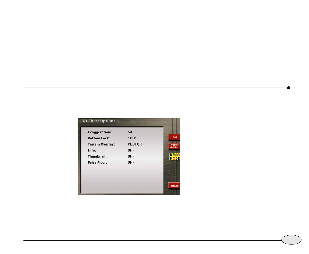
Exaggeration
You can set the amount by which the
terrain height is exaggerated for ease in
viewing. Minor changes in elevation
become visible, in an area that might
otherwise appear flat. Adjust the exaggeration to best fit your needs, from 1X (no
exaggeration) to 60X (extreme exaggeration). The keel marker and depth
automatically adjust to the exaggeration
factor.
Reference Manual Revision B
3D Chart Options
In the Pacific Northwest, exaggeration of
2X usually produces a natural looking
image. In the Northeast, try 3X to 5X. Off
the Florida coast, try 5X to 10X.
Reference section 2 — 3D maps
Configuring the screen
43
Page 48
Bottom lock
Thumbnail
When Bottom lock is activated on the main
3D screen, this setting controls the height
of the camera viewpoint above the seabed.
The camera can be positioned at 25, 50, 75,
100 or 200 feet above the sea floor, to look
directly under the vessel.
Terrain overlay
Choose Vector chart or Aerial/satellite
Photograph to be overlaid on the chart
when Overlay is activated on the 3D
screen.
Flying around the vessel
Vessel Mode
In Vessel mode, press the cursor pad left or
right to fly around your vessel. Press it up
or down to change the elevation of the
viewing point.
Displays a small image of the area
surrounding the vessel in the lower left
corner of the screen, to help identify the
vessel’s location.
False floor
To improve the appearance of
below-the-surface colors, this function
compresses the range so that the full range
of colors is displayed between the surface
and the false floor. Choose Off, 100ft, 250ft,
500ft, 1000ft, 2000ft, 4000ft. (This option
applies only when the Shaded relief is
turned on).
Browse Mode
In Browse mode, press the cursor pad up or
down to move the camera position forward
or back. Press the cursor pad left or right to
control the camera heading and thus the
direction the camera will move when the
cursor pad is pressed up or down. Use the
menu keys to move the camera position up
or down.
44
Reference section 2 — 3D maps
Flying around the vessel
Northstar 972
Page 49
Reference section 3
Position coordinates
Displaying position, COG, and speed . . . . . . . . . . . . . . . . . . . 46
Using GPS. . . . . . . . . . . . . . . . . . . . . . . . . . . . . . . . . . . . . . . . . . . 46
Position screen options. . . . . . . . . . . . . . . . . . . . . . . . . . . . . . . 47
Viewing GPS satellite status. . . . . . . . . . . . . . . . . . . . . . . . . . . 48
Using Phantom Loran . . . . . . . . . . . . . . . . . . . . . . . . . . . . . . . . 49
The POSITION key displays your position coordinates (GPS or Phantom Loran) and lets
you check out GPS signal status. COG, SOG, and time of day are also displayed.
Reference Manual Revision B
45
Page 50
Displaying position, COG, and speed
The 972 uses a high-performance GPS
receiver as its source of position data, with
accuracy enhanced by the WAAS satellite
system. The 972 can display position as
Using GPS
Position, Course Over Ground (COG),
Speed Over Ground (SOG) as well as time
and date are all calculated from the
received satellite data. To display this
position information numerically, press the
POSITION key.
When you’re using
WAAS signals, your
position coordinates,
as calculated by the
972, may actually
exceed the accuracy
of some charts.
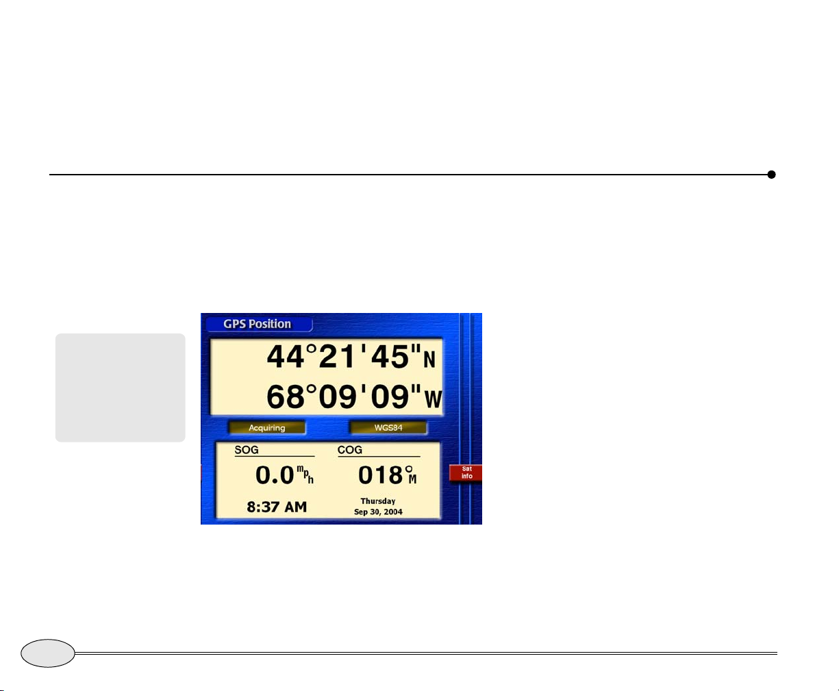
GPS position screen
You’ll see your lat/lon coordinates on the
GPS Position screen.
latitude/longitude coordinates, or as
loran-C coordinates calculated from the
GPS data.
If GPS data isn’t available, you’ll see dashes
instead of numbers.
The time of day, and today’s day and date
are displayed at the bottom of the screen.
The name of the datum currently in use is
displayed in the center of the screen. Each
marine chart uses a coordinate system
described by its datum. Most new charts
use the WGS-84 datum.
When using the 972 with WAAS corrections, you’ll usually see position
measurements accurate to about one to
three meters, speed measurements
accurate to about 0.1 knot, and COG
measurements accurate to about 0.5
degree. WAAS corrections remove most of
the errors caused by atmospheric
variations.
When the WAAS indicator is displayed at
the right edge of the screen, the 972 is
using this higher level of accuracy. When
you require this additional accuracy, be
46
Reference section 3 — Position coordinates
Displaying position, COG, and speed
Northstar 972
Page 51
sure to check often to verify that the
WAAS indicator is present.
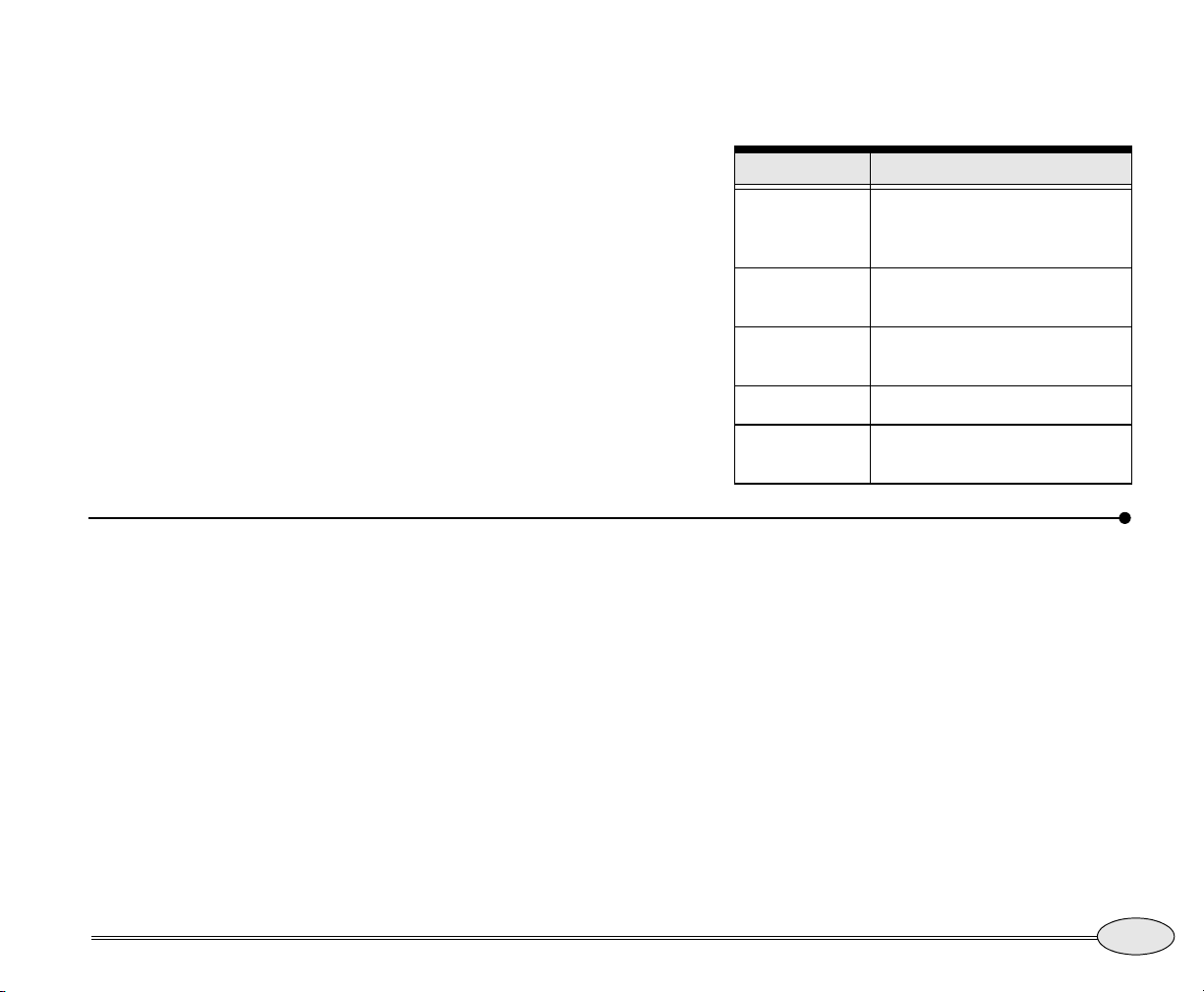
A brief status summary of the GPS receiver
is displayed at the left side of the screen.
Table 1 describes the GPS status messages.
Table 1: GPS status messages
Message Meaning
– – –
the GPS receiver or its
communication link has a
problem
Position screen options
To display the Position screen options, press
and hold
screen.
Dist/speed units
Choose:
• Nautical miles and Knots
• Statute miles and Miles per Hour
• Kilometers and Kilometers per Hour
POSITION while on the Position
3D NAV
2D NAV
ACQUIRE
WAAS
navigating with 4 or more
satellites in 3-D mode
navigating with 3 satellites in
2-D mode
trying to acquire satellites
WAAS signals are being used
for navigation
Magnetic variation
Choose:
• True or magnetic
Lat/lon display
Choose:
• Degrees, minutes and seconds
• Degrees, minutes and thousandths of
minutes
Reference Manual Revision B
Reference section 3 — Position coordinates
Position screen options
47
Page 52
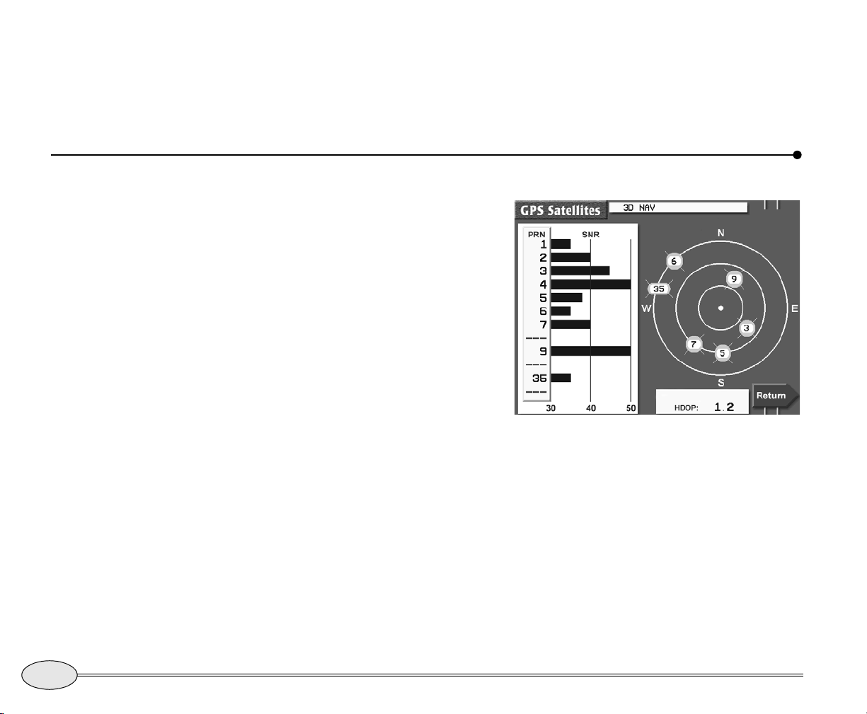
Time format
Choose:
• 12-hour clock or 24-hour clock
Viewing GPS satellite status
To display more information about the
signals received from the GPS satellites,
press Sat info… on the
The
GPS Satellites screen shows the
received Signal-to-Noise Ratio (SNR) for
each satellite (the higher the SNR, the
better the quality of the satellite signals),
and a map indicating where the satellites
are currently located in the sky. The satellites are identified by their PRN number, a
one- or two-digit number assigned by the
U.S. government.
To designate the time zone for your area,
see Changing the time zone, on page 153.
GPS Position screen.
48
GPS satellites are represented by circles;
WAAS satellites are represented by ovals.
The center of the satellite map represents
the center of the sky, and the outermost
ring is the horizon. The view is looking
down from above, with east to your right
and west to your left.
Reference section 3 — Position coordinates
Viewing GPS satellite status
Satellite status screen
HDOP (Horizontal Dilution of Precision) is
a technical measure of the quality of your
position fix. It is calculated from the satellites’ current positions. You’ll usually see
an invalid HDOP value displayed immediately after the 972 is turned on, before it’s
ready to navigate. HDOP can range from
an ideal value of slightly less than one, up
to poor values of 10 or more. Any value
less than two indicates an excellent satellite configuration.
Northstar 972
Page 53
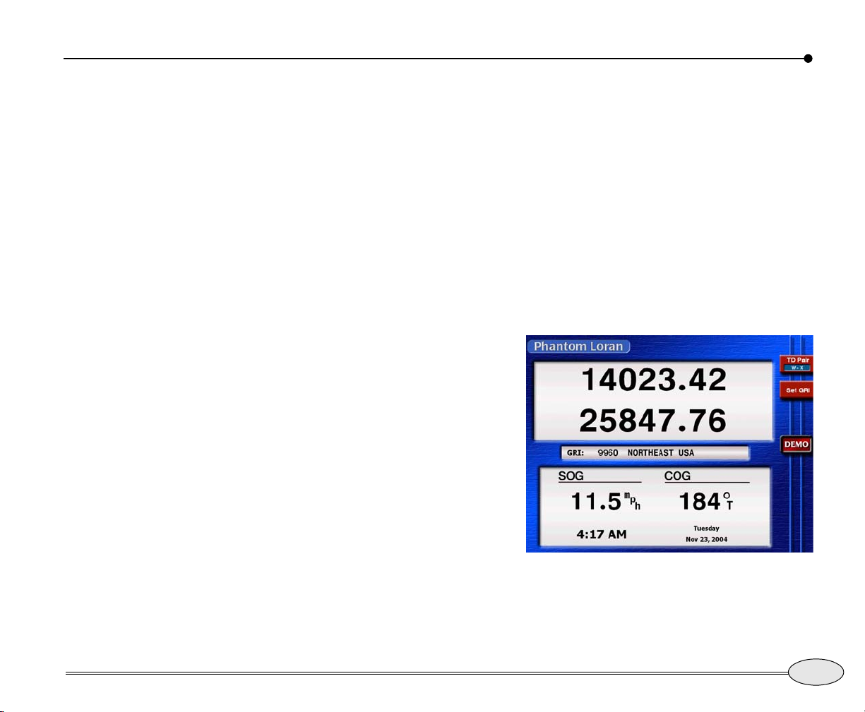
Using Phantom Loran
If you have lists of fishing spots and other
waypoints that you recorded as loran time
differences (TDs), but you no longer have a
loran receiver, the 972 can automatically
convert its GPS coordinates into TDs — in
real time, as you travel. You can display
your current position as TDs or navigate to
waypoints using TDs. The accuracy from
this conversion is generally 500 to 1500
feet.
This feature, called Phantom Loran, can
help your transition from loran to GPS. You
can use the 972 to simulate the full operation of a loran receiver, using all of the
972’s navigation functions as if it were
actually receiving loran signals.
These calculated TDs won’t exactly match
the positions of previously recorded TDs
obtained directly from actual loran signals.
In most areas, TD errors shouldn’t exceed
one microsecond. However, larger errors
are possible in areas with poor station
geometry, or for which the 972 doesn’t
have accurate, factory-programmed ASF
correction points.
key a second time to display the
Loran
screen.
Press it again to return to lat/lon
coordinates.
Phantom
Setting the Phantom Loran GRI
Press Set GRI to change the GRI to be used
in calculating the displayed TDs. Press the
cursor pad to display the available GRIs
one at a time. When the GRI is correct,
press
ENTER.
Reference Manual Revision B
Selecting Phantom Loran
To display position coordinates as
Phantom Loran TDs, press the
POSITION
Phantom Loran screen
Press TD pair several times to display the
pair of TDs you want to use.
Reference section 3 — Position coordinates
Using Phantom Loran
49
Page 54
50
Reference section 3 — Position coordinates
Using Phantom Loran
Northstar 972
Page 55
Reference section 4
Navigating to Waypoints
Introducing waypoints . . . . . . . . . . . . . . . . . . . . . . . . . . . . . . . 52
Designating a waypoint . . . . . . . . . . . . . . . . . . . . . . . . . . . . . . 52
Steering to a waypoint . . . . . . . . . . . . . . . . . . . . . . . . . . . . . . . 54
The course predictor line . . . . . . . . . . . . . . . . . . . . . . . . . . . . . 57
Navigating along routes . . . . . . . . . . . . . . . . . . . . . . . . . . . . . . 58
Restarting the track line . . . . . . . . . . . . . . . . . . . . . . . . . . . . . . 59
Stopping and restarting navigation . . . . . . . . . . . . . . . . . . . . 61
A waypoint is a specific point you designate either by entering its coordinates or by
pointing to it on the chart using the cursor. Hundreds of waypoints can be stored in the
972’s memory, and can be strung together to form a variety of routes.
Reference Manual Revision B
51
Page 56
Introducing waypoints
A waypoint is a point (a location) that
To store a route, see
page 71.
you’ve entered into the 972’s memory. The
waypoint is displayed on the chart with the
symbol you’ve chosen.
Here are some of the functions you can
perform with waypoints:
• go to a point on the Chart screen in one
step (making a “quick” waypoint)
• store waypoints into the 972
Designating a waypoint
• go to these waypoints
• string waypoints together to form
routes
• edit or erase waypoints or routes
• plot waypoints on a chart
• transfer waypoints and routes from the
972 to a PC or an older Northstar
navigator, and back again
52
You can designate waypoints in any of the
following ways:
• use the cursor on the Chart screen to
select an existing waypoint or create a
new waypoint
• enter numeric position coordinates
• select an existing waypoint from a list
You can also string together several
waypoints to form a route, and let the 972
guide you from one waypoint to the next
(see Introducing routes, on page 71).
Reference section 4 — Navigating to Waypoints
Introducing waypoints
Designating a waypoint on the chart screen
You can go to a waypoint by moving the
cursor to that point on the chart — either
selecting an existing waypoint on the
screen, or designating any other location
on the
Chart screen:
1. On the Chart screen, move the cursor pad to
choose an existing waypoint or nav aid, or any
unmarked chart position.
2. Press Go to waypt. (If you didn’t choose a
waypoint, the key will read
Go to cursor or
Go to navaid.)
3. Press ENTER.
If you selected an existing waypoint, the
972 begins guiding you directly to it.
Chart
Northstar 972
Page 57
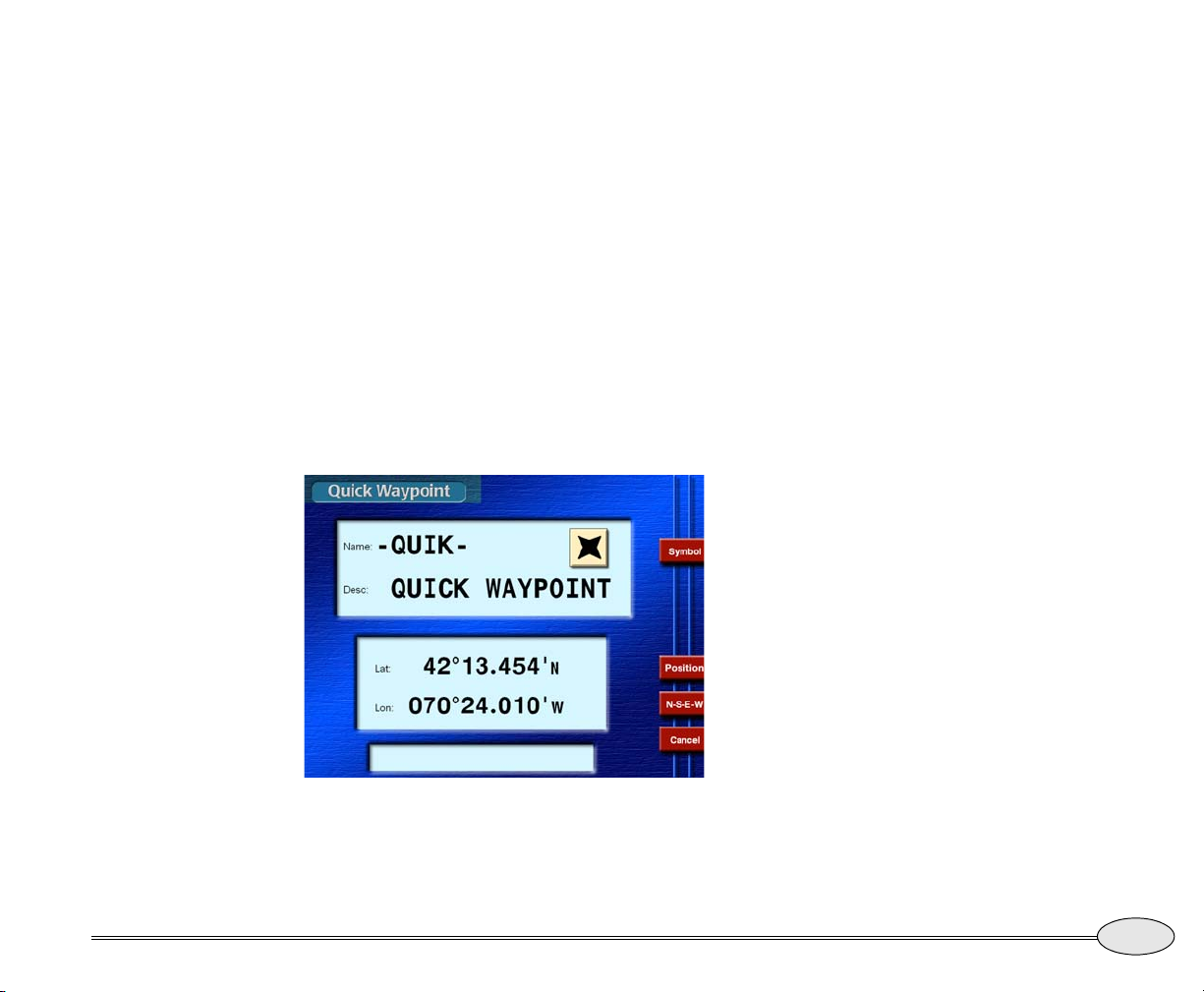
If you chose a new cursor location, the 972
makes a new waypoint named -QUIK-, and
guides you directly to it. Repeating this
same procedure will create a new -QUIKwaypoint that overwrites the existing one;
therefore, you may want to save the -QUIKwaypoint as a regular waypoint by renaming it. See Editing waypoints, starting on
page 69.
Entering a waypoint’s position coordinates
You can use the keypad to enter waypoint
coordinates, and then go to that waypoint:
1. Press WAYPTS/ROUTES, then press Quick
waypoint
screen.
to display the Quick Waypoint
•
Lat/Lon
• Loran — loran TDs (make sure the
GRI displayed is correct, and
change it if necessary)
• Dist / Brg — distance and bearing
from “here” (your present position), or from any waypoint stored
in the 972
3. Use the keypad to enter the waypoint’s coordinates.
The initial position shown is your latest fix.
If you wish, you can now give the
waypoint a unique name after you’ve
entered its coordinates, since the next
-QUIK- waypoint you make will overwrite
this one: Just move the cursor to the
field and change the name from -QUIK- to
a unique permanent name before continuing.
4. Press ENTER twice.
The 972 begins guiding you directly to the
waypoint.
-QUIK-
Using previously stored waypoints
name
Reference Manual Revision B
Quik waypoint screen
2. If necessary, select the type of coordinates
you want to enter by pressing the Position
menu key:
If you have already stored waypoints as
described starting on page 65, you can
select one of these and navigate to it.
1. Press WAYPTS/ROUTES, then press
Waypoints.
2. Press
Next view to display the most conve-
nient view. You can select a waypoint from the
chart view, or from one of the waypoint lists
Reference section 4 — Navigating to Waypoints
Designating a waypoint
53
Page 58
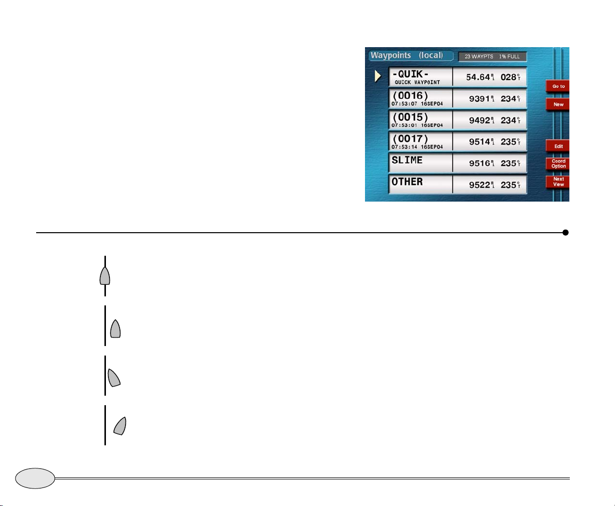
(often the local list, since the waypoints you
navigate to are usually nearby). See Display-
ing waypoints, starting on page 64
3. Press the CURSOR PAD to select the waypoint you want to navigate to.
4. Press
The 972 begins guiding you directly to the
waypoint.
Steering to a waypoint
If your 972 is interfaced to an autopilot, it
1. On track
2. Off track,
come left
to return
3. Off track
and moving
towards
course line
4. Off track
and moving
away from
course line
can steer your vessel automatically along a
track line directly to the active waypoint.
To steer the vessel yourself, press the
STEER key. The 972 displays a picture of
your vessel and the desired track line. Just
steer to keep the vessel close to the track
line (see examples at left).
This precise navigation is especially useful
for following a harbor channel or a line
between shoals and sandbars.
You can also steer using the Chart screen
when you just want to get to a waypoint and
Go to, then press ENTER.
Local waypoints list
don’t need to stay precisely on the
designated course line.
The following is also displayed in the Steer
screen:
• distance and bearing to the waypoint
• Speed-Over-Ground (SOG)
• Course-Over-Ground (COG)
If you exceed the cross-track alarm
distance, the 972 issues an alarm. To
display this alarm message, press the
STAR
key. To clear the alarm, press Clear alarm.
54
Reference section 4 — Navigating to Waypoints
Steering to a waypoint
Northstar 972
Page 59
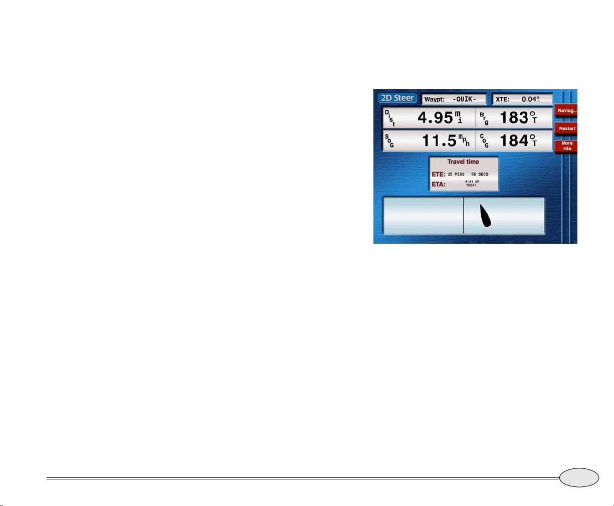
Steer Screens
There are two versions of the steer screen.
The
2D Steer screen is a simple graphic
display of cross-track distance. The
3D Steer
screen is similar, but from an “overhead”
perspective view that also shows nearby
waypoints.
Press
STEER to switch between the screens.
The 2D steering screen
The 2D Steer screen uses a traditional
two-dimensional display that shows your
cross-track distance — how far your vessel
is from your intended track line (the center
line of the display). The vessel symbol on
the display rotates as your vessel turns,
showing whether you are moving closer to
the line or further from the line.
Ideally, you’ll keep the vessel symbol close
to the track line and parallel to it.
The scale of the cross-track display is
shown near the bottom of the screen. To
change the cross-track scale, press the
zoom
IN or OUT keys.
needed to sail parallel to the desired track
line. This is the correction to make after you
are on the line.
2D Steer screen — approaching the track line
The direction in which your vessel symbol
is pointing tells you the direction you’re
actually travelling (your COG). This direction may not be the same as your heading,
if any current or wind is present.
When the 972 sequences to a new leg of a
route, your vessel symbol will immediately
show your COG relative to the new leg.
Reference Manual Revision B
If the cross-track alarm is turned on, the
alarm limits are displayed as red lines
within the cross-track display.
Note that the heading correction display on
the 2D screen (showing “Come 30° Right,”
below) indicates the heading change
Reference section 4 — Navigating to Waypoints
Steering to a waypoint
55
Page 60
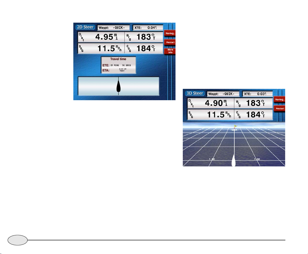
The 3D steer screen
The 3D Steer screen is similar to the 2D Steer
screen. It displays a three-dimensional view
of your vessel with the current waypoint,
the course line to the waypoint, and the
locations of any other nearby waypoints
ahead of your vessel.
2D Steer screen — vessel on track
The distance and bearing to the waypoint,
your Speed-Over-Ground (SOG) and
Course-Over-Ground (COG) are displayed
in the upper half of the screen.
You can display additional information in
the center of the
2D Steer screen by
pressing More info to cycle through the
three choices:
• Travel Time — Estimated Time Enroute
(ETE) to the waypoint, and Estimated
Time and Date of Arrival (ETA)
• Waypoint — Waypoint name,
description, and position coordinates
• SOA — Speed of Advance and graphical
heading correction
You can use the
ZOOM keys to zoom in and
out, changing the scale.
3D Steer screen
56
Reference section 4 — Navigating to Waypoints
Steering to a waypoint
Northstar 972
Page 61
Steering on the chart
You can also steer by watching your
progress directly on the chart screen,
rather than using the steer screens
described above. Several aids in the 972
help you do this:
• dotted green line on the chart shows
the original track line from your initial
vessel position to the waypoint
The course predictor line
The course predictor line (see Using the
course predictor line, on page 38) provides
another effective way to navigate a course
line or even to navigate directly to a point
on the chart. On the chart or radar screen,
just keep the end of the predictor line near
the intended course line, and your vessel
will steer towards and gently merge with
the line.
• dotted red line on the chart shows the
direct line from your current vessel
position to the waypoint
• a pair of blue dotted lines surrounding
the original track line to the waypoint
show the width of the allowable cross
track error. These lines will be present
only if the Cross Track alarm is turned
on)
Note that the blue circle surrounding each
waypoint represents the allowable cross
track error, not the arrival radius.
Reference Manual Revision B
The predictor line is also shown on the 3D
steer screen where it may appear curved to
represent the actual track on the 3D grid.
Reference section 4 — Navigating to Waypoints
The course predictor line
57
Page 62
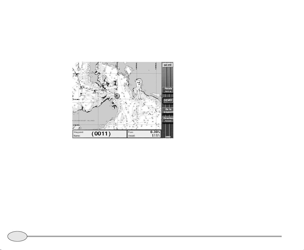
Navigating along routes
To follow a previously stored route, press
WAYPTS/ROUTES, then press Routes to
display the
to select the route you want to follow, then
press Go. The 972 displays a chart showing
the chosen route.
Chart screen, showing a route
From here, you can do the following:
• select a starting waypoint or leg
• start following the route
• reverse the route
Selecting the starting point
The nearest waypoint in the route is automatically selected as the starting point. To
choose a different waypoint or route leg,
press the cursor pad and select it on the
Routes list. Press the cursor pad
chart. You can zoom
smaller or larger area of the route.
IN or OUT to see a
Starting a route
To go directly to the selected waypoint in
the route, press Go to waypt, then press
ENTER. The 972 calculates a track line from
your present position to the selected route
waypoint. Your cross track error starts at
zero.
If you wish to start navigating along a
route leg, rather than directly to a
waypoint, select the leg by moving the
cursor onto the leg, then press Follow leg
and press
cross-track error is your distance from that
leg. Arrows on the leg indicate the direction of travel.
ENTER. In this case, your initial
Reversing a route
To follow the route in the reverse direction, press Reverse before starting the
route. The direction of the route and its
arrows will change from end to end.
58
Reference section 4 — Navigating to Waypoints
Navigating along routes
Northstar 972
Page 63
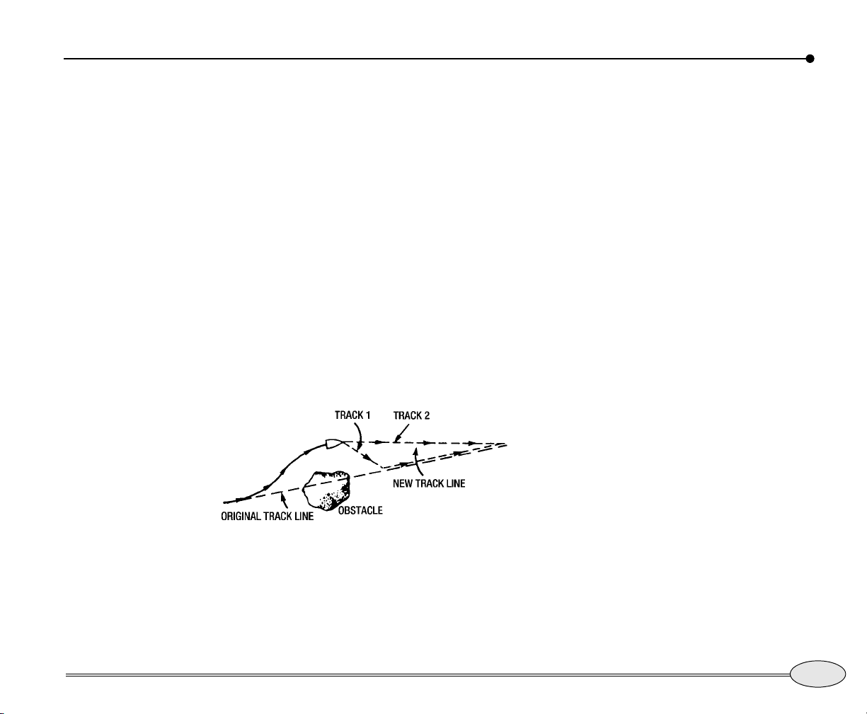
Restarting the track line
When travelling from one waypoint to
another, you may find you’ve gone off
your planned track line. Maybe you
avoided an obstacle or drifted slightly
off-course. Whenever you’re off-track, you
can get back by one of two methods:
• after passing the obstacle, you can steer
your vessel back to the original track
line by using the cross-track error
display, and simply continue to the
waypoint (Track 1 in Figure 2)
• after passing the obstacle, if you don’t
need to return to your original track
line, you can go directly to the next
waypoint by using the 972’s restart
function (Track 2 in Figure 2)
Restart is found on the
vessel mode only) and on the
The 972 calculates a new track line from
your present position directly to the next
waypoint, and resets your cross-track error
to zero.
Chart screen (in
Navlog screen.
Reference Manual Revision B
Figure 2: Restarting the course line
To restart your track line from your
present position, press Restart and
ENTER.
Reference section 4 — Navigating to Waypoints
Restarting the track line
59
Page 64
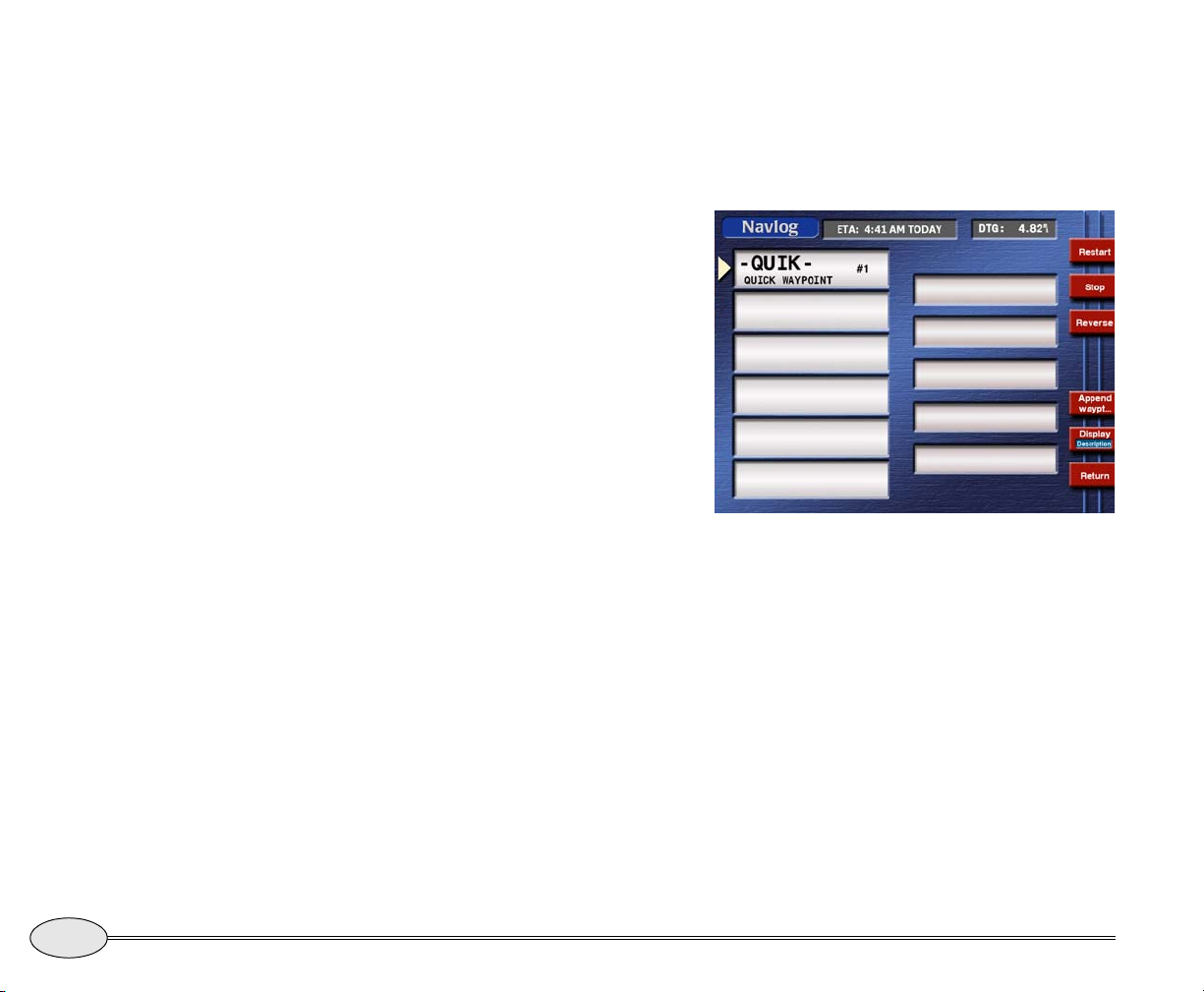
The NAVLOG screen
The Navlog screen displays the waypoints in
your current trip and lets you easily make
changes to them. To access the screen,
press the Navlog key on the
The navlog helps you plan and log your
trip, using three main functions:
• displaying your progress along your
trip
• allowing you to easily change the rest
of your trip (add waypoints to a route,
or reverse the entire trip)
• allowing you to sequence to the next
leg, if you’ve chosen manual waypoint
sequencing
The nav log contains the series of
waypoints that you follow along your route
and displays them in sequential order.
When you navigate to these waypoints, or
along an already stored route, the series of
waypoints is copied into the nav log, which
acts as a kind of “scratch pad” to monitor
your progress. You can change the nav
log’s route in any way you want without
affecting the original route, which remains
safely stored in the 972.
To see the waypoints you’re currently navigating along, press the Navlog key on
either
Steer screen.
Steer screen.
The
Navlog screen shows the list of
waypoints, the length and bearing of each
leg, and the direction of your next trip leg.
Navlog screen
Press the cursor pad to scan the waypoints
in the list.
To display either a waypoint’s description
or its estimated time of arrival (ETA), press
the Display menu key. For waypoints you
haven’t passed yet, the times of arrival
shown are estimates based on your current
speed. For waypoints you’ve already
passed, actual times of arrival are shown.
The 972 updates this information as you
travel.
60
Reference section 4 — Navigating to Waypoints
The NAVLOG screen
Northstar 972
Page 65
NOTE:
Estimated times are just estimates, which
may be inaccurate if your SOG changes,
either intentionally or by passing through
varying currents.
Your ETA at the last waypoint (your destination) is shown at the top of the screen. A
red arrow connecting the right ends of two
waypoint boxes indicates you’ve completed
that leg of the trip.
Changing your trip
Adding waypoints to your trip
You can add waypoints to your trip at any
time:
1. On the Navlog screen, press the Append
waypt
menu key to display a chart view of
the trip waypoints on the Append Waypt
screen.
2. Press the cursor pad to select the desired
waypoint.
3. Press the
press the ENTER key to add the waypoint to
the nav log.
Any waypoints added in this manner aren’t
permanently added to the original route
stored in the 972. To permanently change a
route, you must use the edit-route function.
(For details, see ”Editing a route” starting on
page 76.)
Select waypt menu key, then
NOTE:
4. Repeat these steps for any more waypoints
you want to add.
NOTE:
If you go to a waypoint or along a route by
using the 972’s GO TO function, the unit
automatically enters and organizes the
waypoints in the navlog.
Reversing your trip
You can reverse your trip at any time.
Pressing the Reverse menu key on the
Navlog screen lets you travel the trip in the
opposite direction.
Stopping and restarting navigation
Stopping navigation
Whenever you press the navlog’s Stop
menu key, the 972 stops navigating, and
won’t display distance and bearing to
waypoints or ETA or ETE.
Restarting navigation
You can restart navigation along any leg or
to any waypoint of the trip. On the
screen, move the cursor arrow to highlight
the waypoint or leg. When you select a
waypoint, a triangle points to the waypoint.
When you select a leg, an arrow points
from the first waypoint to the second. Press
the Restart menu key.
Navlog
Reference Manual Revision B
Reference section 4 — Navigating to Waypoints
The NAVLOG screen
61
Page 66
Editing the Navlog
You can add or delete waypoints from the
navlog, provided you first stop navigation
as described above.
You can clear the Navlog by pressing
and
ENT while the navlog is displayed
CLR
62
Reference section 4 — Navigating to Waypoints
The NAVLOG screen
Northstar 972
Page 67
Reference section 5
Creating waypoints and routes
Displaying waypoints . . . . . . . . . . . . . . . . . . . . . . . . . . . . . . . . 64
Creating new waypoints . . . . . . . . . . . . . . . . . . . . . . . . . . . . . . 65
Creating avoidance-area waypoints . . . . . . . . . . . . . . . . . . . . 68
Editing waypoints. . . . . . . . . . . . . . . . . . . . . . . . . . . . . . . . . . . . 69
Introducing routes . . . . . . . . . . . . . . . . . . . . . . . . . . . . . . . . . 71
Creating a route from the chart . . . . . . . . . . . . . . . . . . . . . . 72
Creating routes from a list of waypoints . . . . . . . . . . . . . . 73
Saving a route as you travel . . . . . . . . . . . . . . . . . . . . . . . . 74
Editing a route . . . . . . . . . . . . . . . . . . . . . . . . . . . . . . . . . . . . 76
Transferring waypoints/routes to other units . . . . . . . . . . . 80
Transferring waypoints to and from a PC . . . . . . . . . . . . . . . 83
This chapter explains how to create new waypoints and modify existing ones, how to
make a route from stored waypoints, and how to create a route by saving it as you travel.
You’ll also learn how to change a route by inserting, removing or changing the order of
its waypoints.
Reference Manual Revision B
63
Page 68
Displaying waypoints
To display waypoints, press the
WAYPTS/ROUTES key, then Waypoints. You
can press Next view to step through the
four available waypoint screens listed
below:
• waypoints displayed on the chart
• a list of up to 30 local waypoints, sorted
by distance (nearest first)
• a list of all waypoints, sorted
alphabetically
• a list of up to 30 local avoidance
waypoints, sorted by distance (nearest
first)
The waypoint screen type is shown in the
upper right corner.
Waypoints on the chart screen
The Waypoints chart screen displays your
waypoints graphically. You can press the
cursor pad to display other areas of the
chart, and press the
see more or less chart area.
If you’ve turned off the display of waypoints
on the Chart screen, you’ll only see
waypoints that are currently in use for
navigation.
OUT or IN zoom keys to
NOTE:
Waypoints on the local list
The Waypoints (local) screen displays up to
30 of the closest waypoints (within 100
nm) in order of their distance from your
present position. This list is particularly
useful for working with the waypoints in
your area. Often these are the only
waypoints you may be interested in at the
moment.
Waypoints on the alpha list
The Waypoints (alpha) screen displays all
stored waypoints in alphabetical order.
Waypoints with a digit as the first character appear at the beginning of the list.
Those starting with a dash or parenthesis
are at the end.
Waypoints on the avoidance list
The Waypoints (avoidance) screen displays up
to 30 of the closest avoidance waypoints
(within 100 nm) in order of distance from
your present position.
Using the waypoint lists
After you’ve stored a few waypoints in the
972, you can press the cursor pad to move
64
Reference section 5 — Creating waypoints and routes
Displaying waypoints
Northstar 972
Page 69
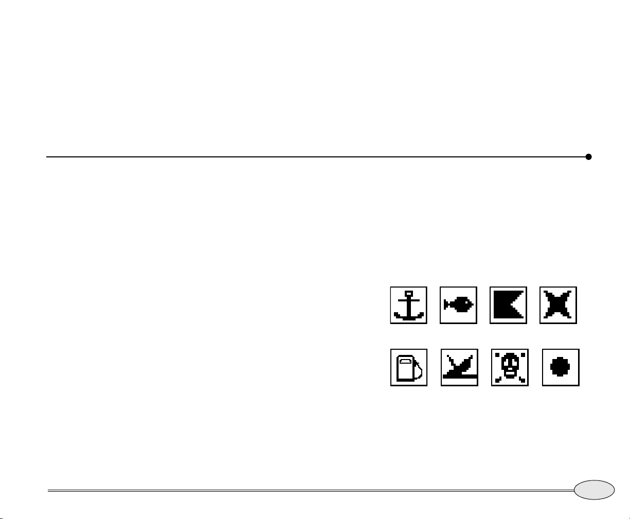
up or down within a waypoint list to select
individual waypoints.
When you display a waypoint list, you can
see their coordinates in either of the
following ways by pressing the Position
menu key:
Creating new waypoints
• as lat/lon coordinates
• as distance and bearing from your
position (often the most useful way to
display coordinates, since it may be
easier to visualize “3 miles north” than
lat/lon digits)
• as Loran TD’s
Reference Manual Revision B
There are two easy ways to create a new
waypoint:
• numerically — by entering position
coordinates as lat/lon, loran TDs, or
distance and bearing on the
Waypoint
• from the chart — by pointing to the
waypoint’s location on the
screen
New
Chart screen
Assigning a name and description
To permanently store a waypoint, you
must give it a name. The name can be from
one to six characters long, and must be
different from all the other waypoint
names stored in the 972. You can also
enter a description of up to 16 characters
on the line below the name.
Reference section 5 — Creating waypoints and routes
Assigning a symbol
You can give the waypoint a symbol so
you can easily identify it on the
screen. When creating or editing
waypoints, you can choose from a list of
symbols, displayed in the upper right
corner.
ANCHOR FISH FLAG X
FUEL WRECK DANGER DOT
Figure 3: Typical waypoint symbols
Creating new waypoints
Chart
65
Page 70
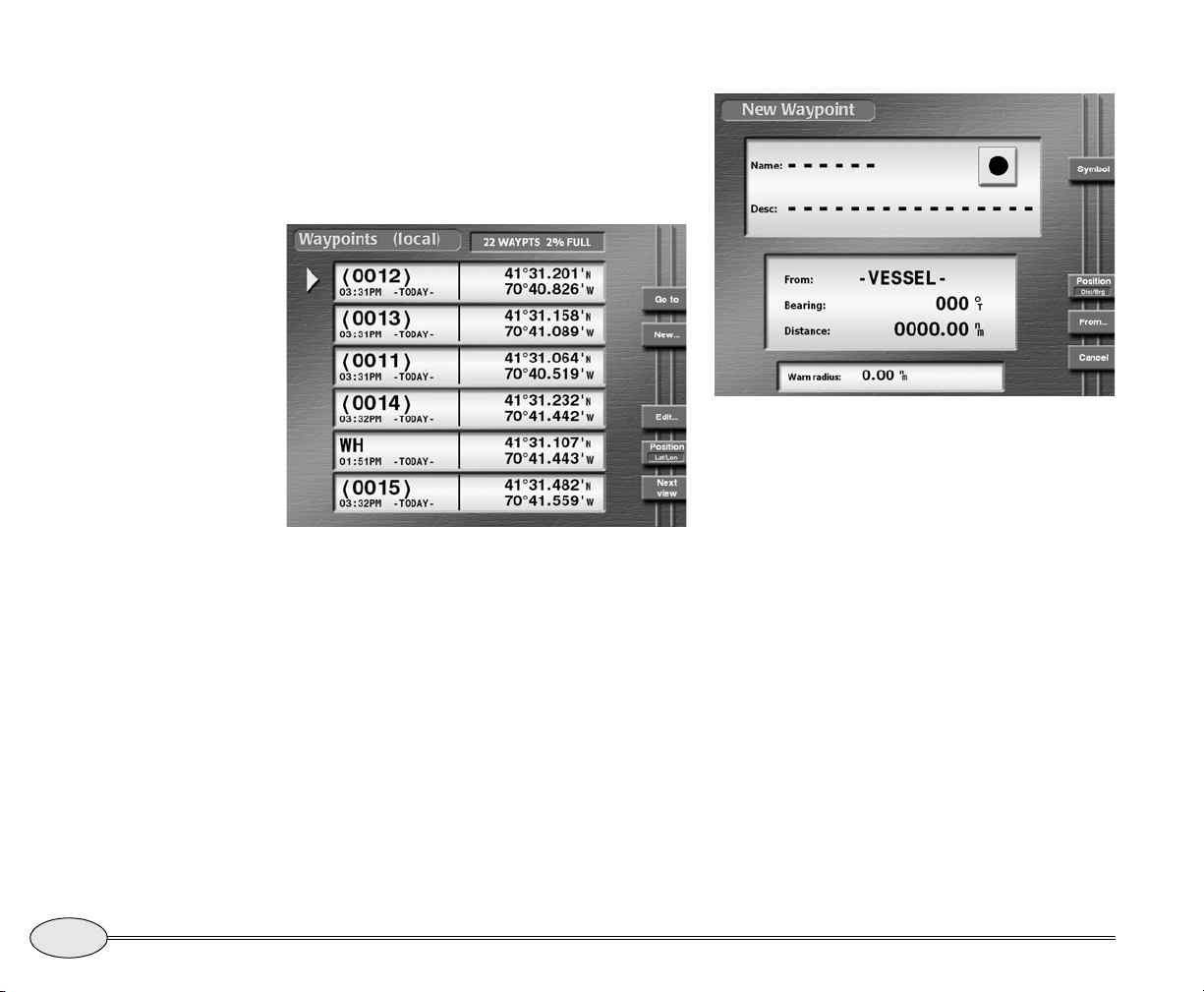
Entering waypoints numerically
To enter waypoints numerically:
1. Press WAYPTS/ROUTES.
2. Press
3. Press New… to display the New Waypoint
Waypoints…
Local Waypoints screen
screen.
New Waypoint screen
4. Enter a waypoint name and optional description.
Press (several times if necessary) the key
on the 972 keypad that contains the letter
or digit you wish to enter. Press the cursor
pad when necessary to move the cursor to
the next character.
5. Choose a symbol for the waypoint by repeatedly pressing
6. Enter the waypoint’s coordinates. To switch
between displaying coordinates as lat/lon, as
loran TDs, or as distance and bearing coordinates, press
• For lat/lon, the N-S-E-W key lets
Symbol.
Position:
you manually change the
hemisphere, if necessary.
66
Reference section 5 — Creating waypoints and routes
Creating new waypoints
Northstar 972
Page 71
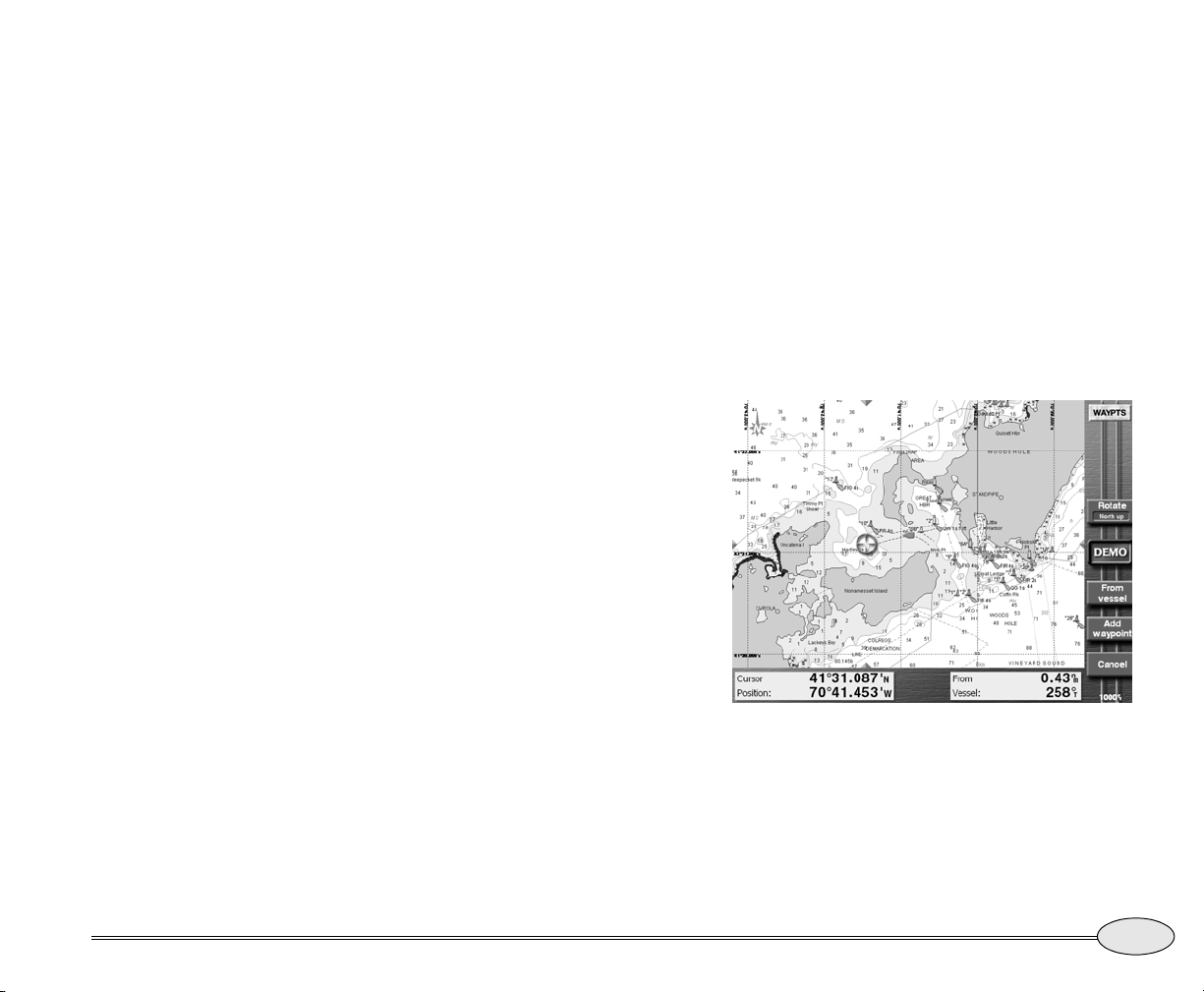
• For loran TDs, enter any valid pair
of TDs and the GRI for the pair.
After entering the GRI, check the
name of the GRI that’s
automatically displayed to ensure
it’s correct.
• For distance and bearing from your
present position, leave the From
point set to -VESSEL-, and enter
the bearing and the distance to the
desired waypoint.
• For distance and bearing from a
waypoint, press the From menu
key to display a chart screen. Press
the cursor pad to select the desired
waypoint and press Select
waypoint, or create a new
waypoint at the cursor location by
pressing Add waypoint followed
by Select waypoint. Enter the
bearing and the distance from the
designated waypoint to your new
waypoint.
If you change your mind and want to
return to specifying distance and
bearing from your present position
instead of from another waypoint,
From vessel on the chart
press
screen.
7. Press ENTER to permanently store the new
waypoint.
NOTE:
Don’t enter a number into the Warn radius
box unless you want to make this waypoint
an avoidance point, as described in the next
section.
Entering waypoints on a chart screen
To enter waypoints on a Chart screen:
1. Press WAYPTS/ROUTES.
2. Press
3. Press the cursor pad to move the cursor to
Waypoints. If necessary, press Next
view
to display the Waypoints chart screen.
Waypoints chart screen
the position of the new waypoint. You can
zoom in or out, as necessary, to precisely
place your waypoint.
Reference Manual Revision B
Reference section 5 — Creating waypoints and routes
Creating new waypoints
67
Page 72
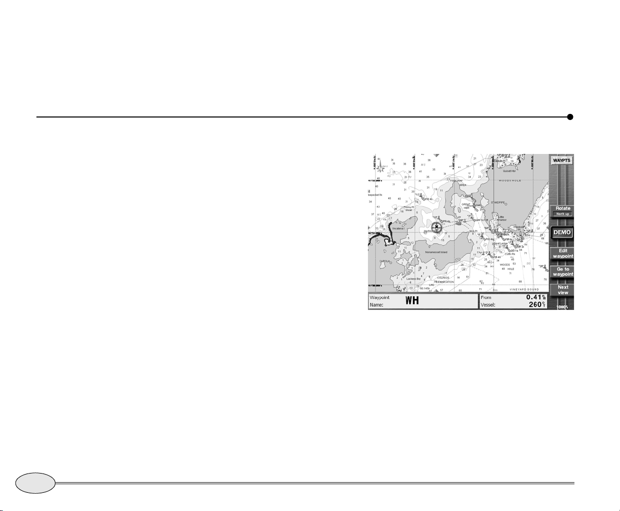
4. Press Add waypoint to capture the cursor
coordinates and display the New Waypoint
screen.
Creating avoidance-area waypoints
5. Now follow the instructions above for entering
a waypoint numerically, starting with Step 4.
The coordinates of the cursor (Step 6) will be
already entered — don’t change them unless
you mean to.
You can make avoidance areas from new or
existing waypoints. Then, if you travel into
a designated avoidance area, the 972 will
sound a beep and flash an alarm on the
screen.
The 972 displays an avoidance area on the
Chart screen as a waypoint surrounded by a
circle. The circle is the avoidance area’s
warning radius, which you set when you
create or edit the waypoint. You can use
the international “slashed circle” no-entry
symbol as the avoidance point’s symbol to
help you quickly see it on the chart.
The waypoint is treated as an avoidance
point only if you specify a warning radius
larger than zero. In other words, just
assigning the slashed circle symbol to a
waypoint doesn’t cause the 972 to treat that
waypoint as an avoidance point.
68
Reference section 5 — Creating waypoints and routes
Creating avoidance-area waypoints
Northstar 972
Page 73
To make any waypoint act as an avoidance
point, enter a number in the
box at the bottom of the
Editing waypoints
You can change any information about an
existing waypoint (except for the type of
coordinates used to save it) or erase it
entirely by using the 972’s waypoint
editing function.
CAUTION!
The avoidance alarm is only an extra safety
feature to help alert you to possible hazards. It
doesn’t replace local knowledge, proper use of
charts, the person on watch, or any other
aspects of good seamanship that are required
to safely navigate.
Warn radius
New Waypoint or Edit
Waypoint
screen. The warning radius can be
from 0.1nm to 4.99 nm.
Be sure to allow a little extra distance
around the hazard area so you’ll have time
to respond by turning or stopping after you
hear the alarm, and to allow for the typical
accuracy of the navigation source in use.
Setting the avoidance-area alarm
The 972 will sound an audio alarm when
you enter an avoidance area, provided
you’ve turned on the audio alarm. (See
“Alarm audio” on page 136.)
2. Select the waypoint by highlighting it with the
cursor pad.
Reference Manual Revision B
Changing waypoints
To change a waypoint’s name, description,
position coordinates, or warning radius:
1. Press WAYPTS/ROUTES, then Waypoints.
If necessary, press
waypoint screen you want.
Next view to display the
Reference section 5 — Creating waypoints and routes
Editing waypoints
69
Page 74
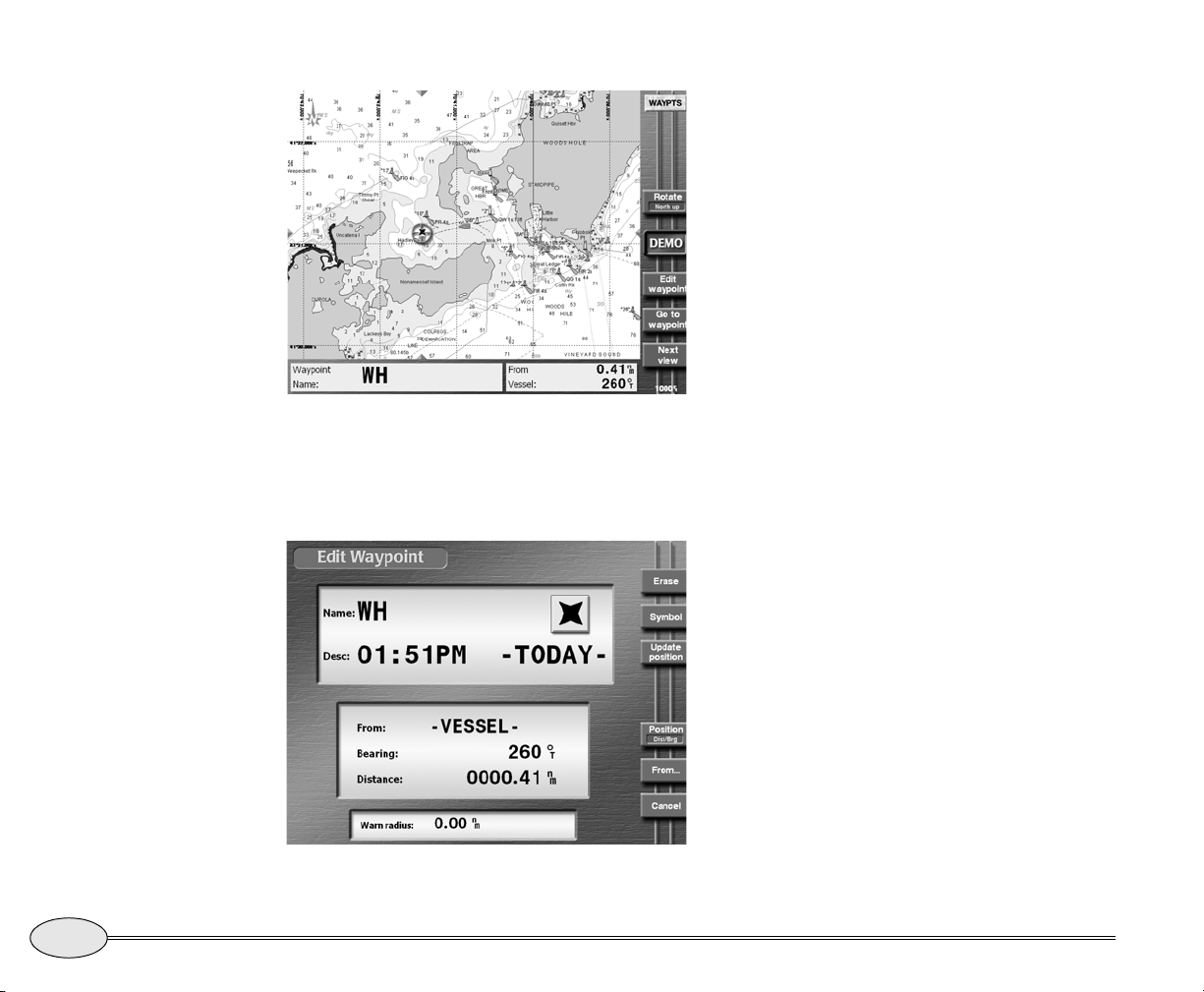
Waypoint “WH” selected
3. To edit the waypoint, press Edit. (On the
Waypoints chart screen, the key is labelled
Edit waypt.)
The Edit Waypoint screen appears, allowing
you to make changes just as if you were
entering a new waypoint. Press
ENTER
when done.
If the waypoint is in an active navplan, you
must stop navigating before editing it.
NOTE:
If you move the waypoint, any routes
containing this waypoint will be changed to
reflect the waypoint’s new position.
A warning is displayed before any routes
are changed.
Erasing waypoints
To permanently erase the waypoint, press
Erase on the
ENTER.
You can’t erase a waypoint if it’s used in a
route—you must first remove it from the
route. For details about editing routes, see
Editing a route, starting on page 76.
Edit Waypoint screen, then
70
Edit Waypoint screen
Reference section 5 — Creating waypoints and routes
Editing waypoints
Updating waypoint coordinates
You can “fine tune” a waypoint’s position
by actually sailing to the exact desired
position and setting the waypoint’s stored
coordinates to your present position. You
Northstar 972
Page 75
can do this on the Waypoints chart screen or
any of the waypoint list screens.
To update the waypoint’s coordinates to
your exact position, display the
Introducing routes
Edit Waypoint
screen for the waypoint as described
above. When your position is correct, press
Update position and
ENTER.
A route is a sequence of waypoints that you
designate. Routes can be used to perform
the following functions:
• as guidance through a channel or
harbor
• as a quick and efficient path to good
fishing spots
• as the best way around a permanent
obstacle, such as an island
• as guidance on a single long voyage
with various “legs” to food and fuel
stops along the way, or to other
temporary destinations
Waypoints in a route are connected by
straight lines called legs. The 972 can
follow route legs in a forward or backward
direction. You can start following a route in
either of two ways:
• go directly to any waypoint in the
route, then automatically continue on
the next leg (cross-track distance starts
at zero, because you’re on the course
line from your present position to the
waypoint)
• start along any leg of the route
(cross-track distance starts at your
distance from the leg)
See ”Navigating along routes” beginning on
page 58.
You can create a route in three different
ways:
• use the Chart screen to choose a
sequence of waypoints
• use a waypoint list to choose a
sequence of waypoints
• save a route’s waypoints as you travel
Route and waypoint capacity
A route can have up to 35 waypoints. You
can store as many as 500 routes in the 972,
but the maximum number depends on the
number of stored waypoints. Each route
takes up space that otherwise could be
occupied by one or two waypoints.
Reference Manual Revision B
Reference section 5 — Creating waypoints and routes
Introducing routes
71
Page 76
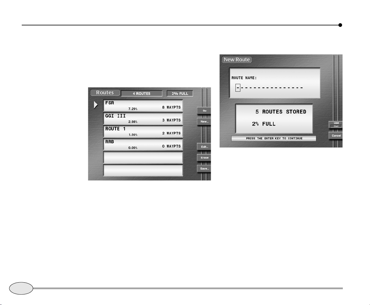
Creating a route from the chart
To create a route graphically from the Chart
screen:
1. Press WAYPTS/ROUTES, and then press
Routes.
The names of any previously stored routes
are shown on the
Routes list screen
routes list.
2. Press New… to display the New Route
screen.
New Route screen
3. Enter the name of the new route using the
keypad and cursor pad.
4. If the
5. Press ENTER.
6. To add waypoints to the route, move the cur-
Use Chart menu key is displayed,
press it to change from list-based entry to
chart-based entry.
The New Route chart screen is displayed;
you may now start selecting waypoints for
the new route.
sor to the first waypoint’s location, which can
be a nav aid, an existing waypoint, or any
unmarked point on the chart. Press
Add
72
Reference section 5 — Creating waypoints and routes
Creating a route from the chart
Northstar 972
Page 77
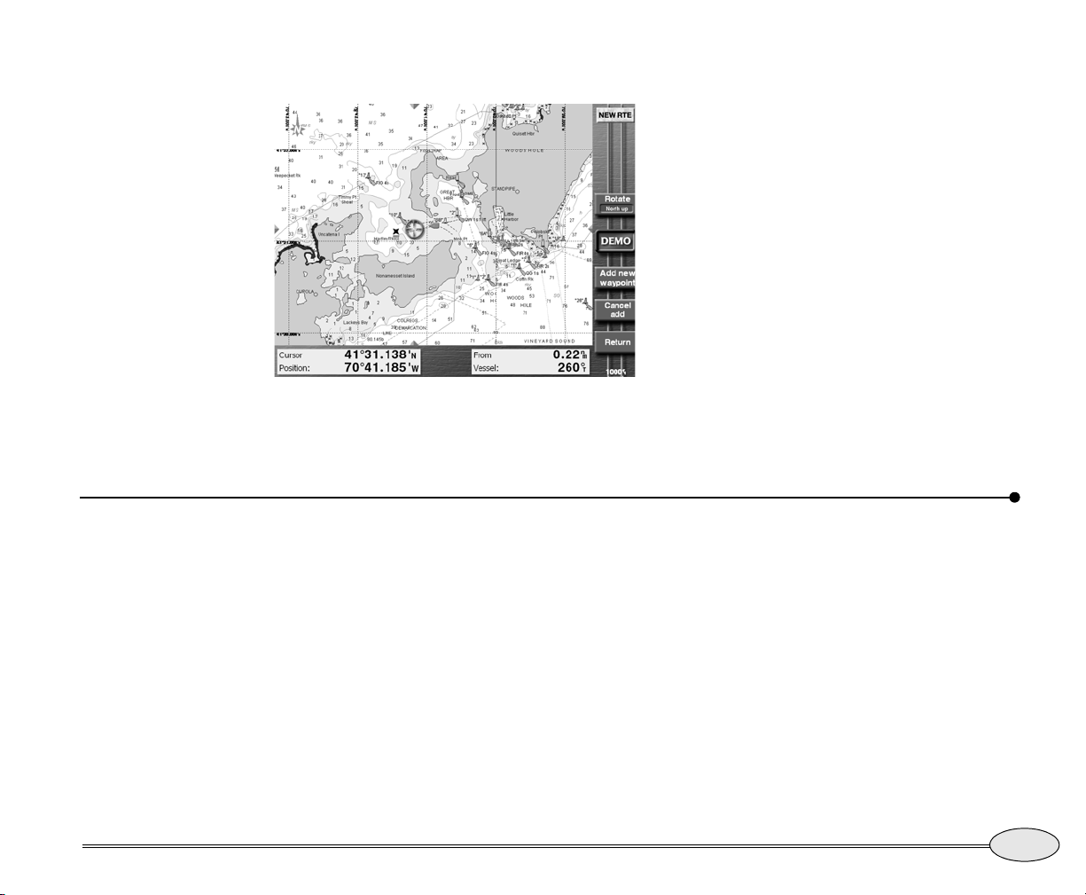
new WP. (If an existing waypoint is selected,
the menu key will read
New Route chart screen
Newly created waypoints are named (0001),
(0002), etc. The parentheses indicate that the
Add waypt.)
Creating routes from a list of waypoints
waypoint was automatically named, and the
four-digit number uniquely identifies each
waypoint. Also, each new waypoint is automatically given a description showing the time
and date you stored the waypoint.
7. Continue creating the route by moving the
cursor to each desired waypoint location and
pressing either
WP
. A line is drawn on the new route screen
connecting the waypoints, with small arrows
indicating the direction of the route.
8. At any time, you can press
stop appending waypoints, and then select a
route leg or waypoint to continue editing a different part of the route.
9. When finished, press
New Route screen to see all of the route’s
waypoints.
Add waypoint or Add new
Cancel add to
Return to switch to the
Reference Manual Revision B
To create a route from a list of existing
waypoints:
1. Press WAYPTS/ROUTES, then press
Routes.
2. Press
3. Enter the name of the route using the keypad
4. Press
5. Press ENTER.
New to display the New Route screen.
and cursor pad.
Use to change from chart-based edit-
ing to list-based editing.
Reference section 5 — Creating waypoints and routes
6. Press
7. If you want to switch between the local and
8. Move the cursor to select the desired way-
9. Repeat Steps 6, 7 and 8 until your new route
Insert…
The Select waypt screen appears, listing all
of your stored waypoints.
alpha
lists, press Next view.
point, then press ENTER to place the waypoint in your route. Or, press
new waypoint, then add it to the route.
is complete.
Creating routes from a list of waypoints
New to create a
73
Page 78
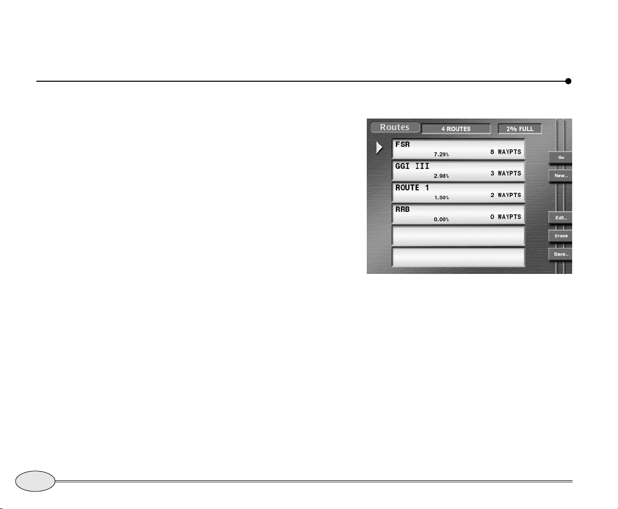
To see or edit the route on the Chart
screen at any time, press CHART
Saving a route as you travel
To make a record of a trip that you may
want to repeat later, you can save
waypoints into a route as you travel by
pressing the
pass a point you want to store in the route.
The save-route function makes this a very
simple process: First, you tell the 972 that
you want to save a route as you travel,
then you press
new waypoint, then you tell it to stop
saving the route when you reach the end
of the route.
To begin saving a route as you travel:
1. Press WAYPTS/ROUTES, and then press
Routes to display the Routes screen:
SAVE/MOB key every time you
SAVE/MOB as you pass each
. Press
Return to go back to the new route entry
screen.
Routes screen
2. Press the
route automatically.
The Save Route screen is displayed, asking you to enter the name of the new route
to be saved.
If you use the name of any existing route,
waypoints will be added to the end of that
route.
Save menu key to set up saving a
74
Reference section 5 — Creating waypoints and routes
Saving a route as you travel
Northstar 972
Page 79
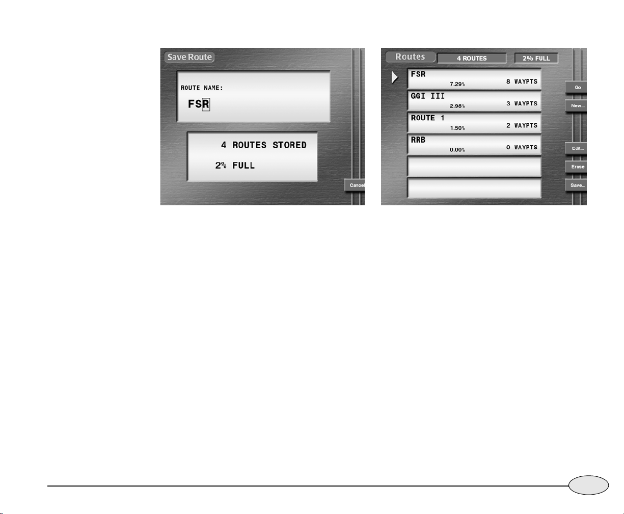
Save Route setup screen Routes screen — saving a route
Reference Manual Revision B
Enter the name of the route to be saved using
the keypad and cursor pad, then press
ENTER.
The unit displays the message “
route:”
at the bottom of the Routes screen,
confirming the name of the route being
saved.
saving to
Reference section 5 — Creating waypoints and routes
3. As you pass the location of each desired waypoint, press SAVE/MOB.
The vessel’s location will be saved as a
waypoint, and the waypoint will automatically be added to the route being saved.
The waypoint is stored with a name similar
(0001). The parentheses indicate that
to
the waypoint was automatically named,
and the four-digit number uniquely identifies each waypoint. Each waypoint is also
given a description with the time and date
you stored the waypoint.
NOTE:
While you’re automatically saving a route,
you can also access all of the unit’s
navigation functions (except you can’t edit
the route you’re presently saving).
To check whether you’re still saving a route,
press WAYPTS/ROUTES, then
Saving a route as you travel
Routes to
75
Page 80
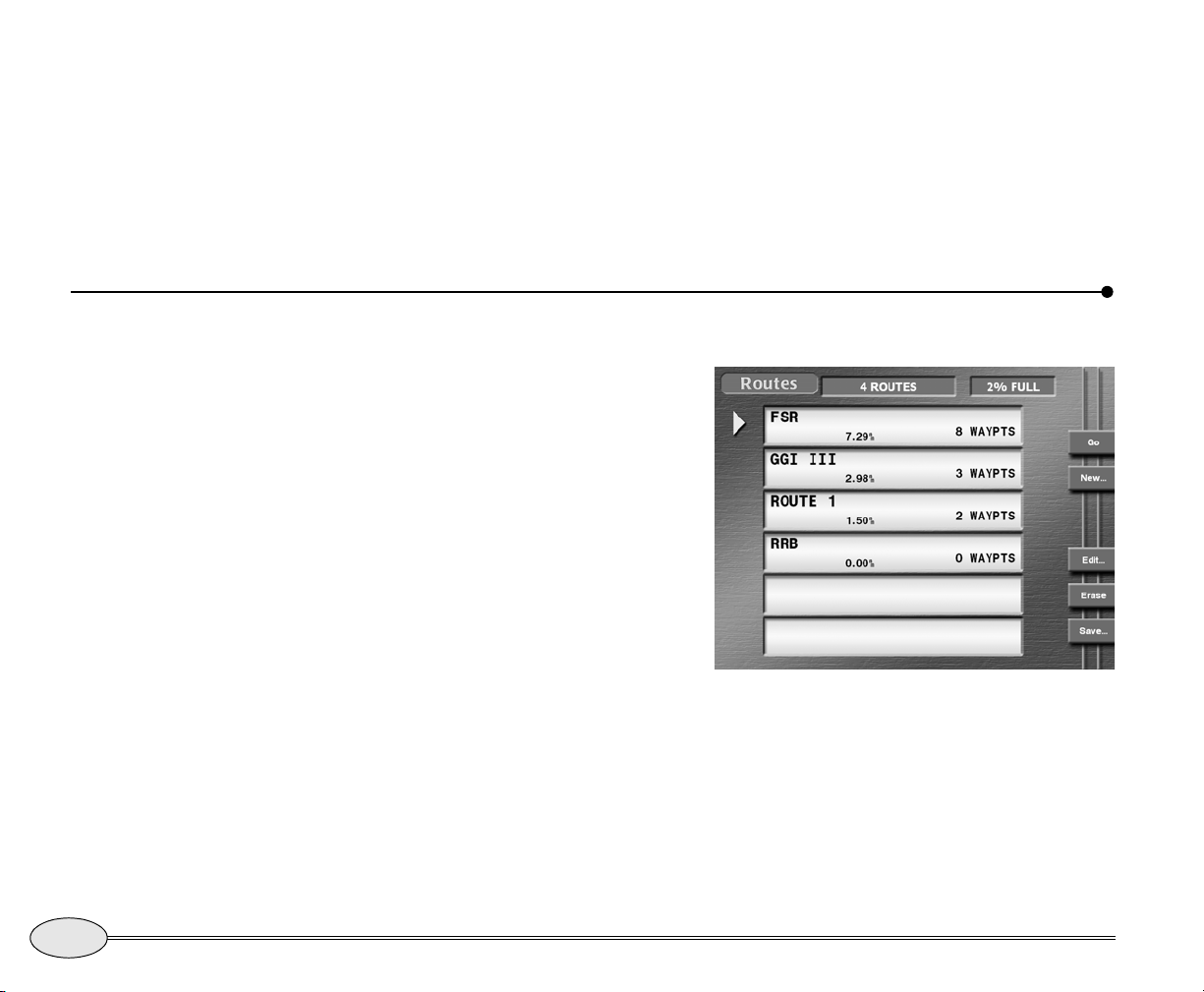
Editing a route
display the Routes screen. If you’re still
saving a route, the message “saving to
route:”
is displayed at the bottom of the
screen.
If the route becomes full (35 waypoints), you
may want to stop saving to this route and
start a second one.
You can make changes to a route graphically using the
Chart screen or you can
change it using a list of its waypoints.
You can make any of the following
changes:
• change the route name
• add new or existing waypoints to the
beginning, middle, or end of the route
• remove waypoints from the route
• erase the entire route
To stop saving a route:
1. Press WAYPTS/ROUTES, then press
Routes.
2. Press
Stop save and ENTER twice.
76
To edit a route:
1. Press WAYPTS/ROUTES, then press
Routes to display the Routes screen.
Reference section 5 — Creating waypoints and routes
Editing a route
Routes screen
2. Press the cursor pad to select the route you
want to change, then press Edit. The name
of the route is displayed on the Edit Route
screen.
Northstar 972
Page 81
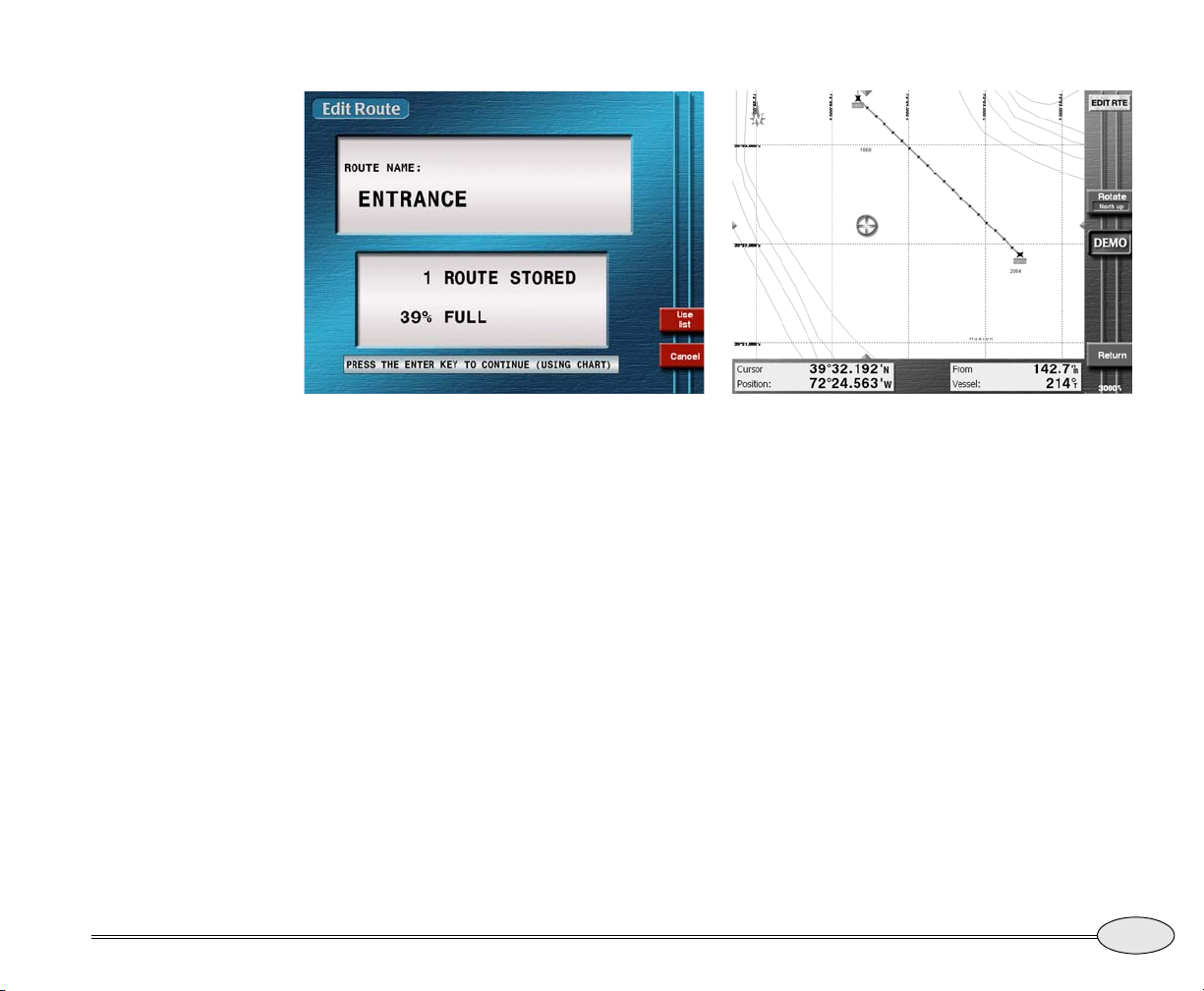
Reference Manual Revision B
Edit Route screen
3. If you want to change the route’s name, do so
now.
4. Press
5. Press ENTER.
Use to change from chart-based edit-
ing to list-based editing.
You can alternate between list and chart
editing at any time.
Reference section 5 — Creating waypoints and routes
Editing a route on the chart
The direction of the route is indicated by a
series of small arrows in each leg, and the
cursor is in the middle of the screen.
Editing from the chart is described below;
editing from a list of waypoints is described
in Editing a route using a waypoints list,
starting on page 78.
Editing a route using the chart
After you have accessed a route as
described above, you can add or remove
waypoints using the chart as follows:
Adding waypoints to a route
You can add waypoints to the end of a
route, or to the beginning, or the middle,
depending on the choice you make in step
Editing a route
77
Page 82
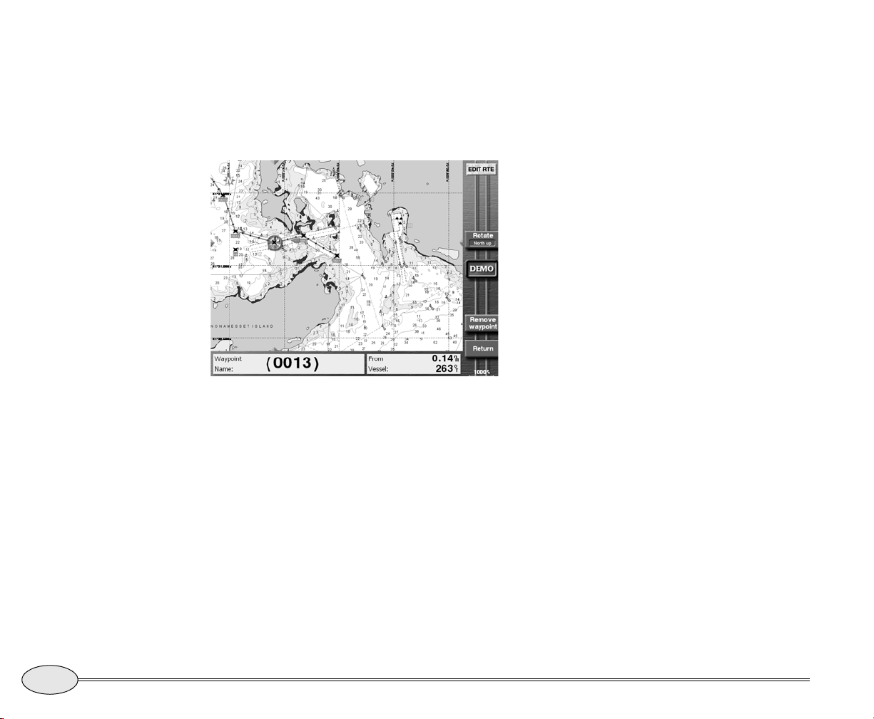
one below. After having accessed a route,
as described in Editing a route, starting on
page 76:
1. Press the cursor pad to move the cursor onto
the route’s last waypoint (or first waypoint, or
a leg).
Waypoint (0001) selected in the route
2. Press
Add to end (or Add to front or
Split leg).
3. Move the cursor to the location that you want
to add to the route (either an existing waypoint, or any other spot).
As you move the cursor, the 972 displays
the new route leg as a dotted line to the
cursor position.
4. Press a menu key once to add the waypoint:
•
If you selected an existing
waypoint, the key is marked Add
waypoint.
• otherwise, the key will read Add
new waypoint.
• If you’re adding a waypoint to a leg,
the key is marked Split leg. Move
the cursor to the new waypoint
position and press Insert new
waypoint.
5. Repeat for each new waypoint or cursor location you want to add to the route.
6. When you’re finished, press
Instead, you can press
list-based editing.
Cancel add.
Return to switch to
Removing waypoints from a route
To remove waypoints from the route (the
waypoint is not erased from the 972):
1. Move the cursor to the waypoint you want to
remove, then press Remove waypt.
Even if you remove all the waypoints from a
route, the 972 still retains the empty route.
To remove the route entirely, see Erasing
an entire route, on page 79.
2. When done, press
editing.
Return to go to list-based
Editing a route using a waypoints list
After you have accessed a route, as
described in Editing a route, starting on
78
Reference section 5 — Creating waypoints and routes
Editing a route
Northstar 972
Page 83
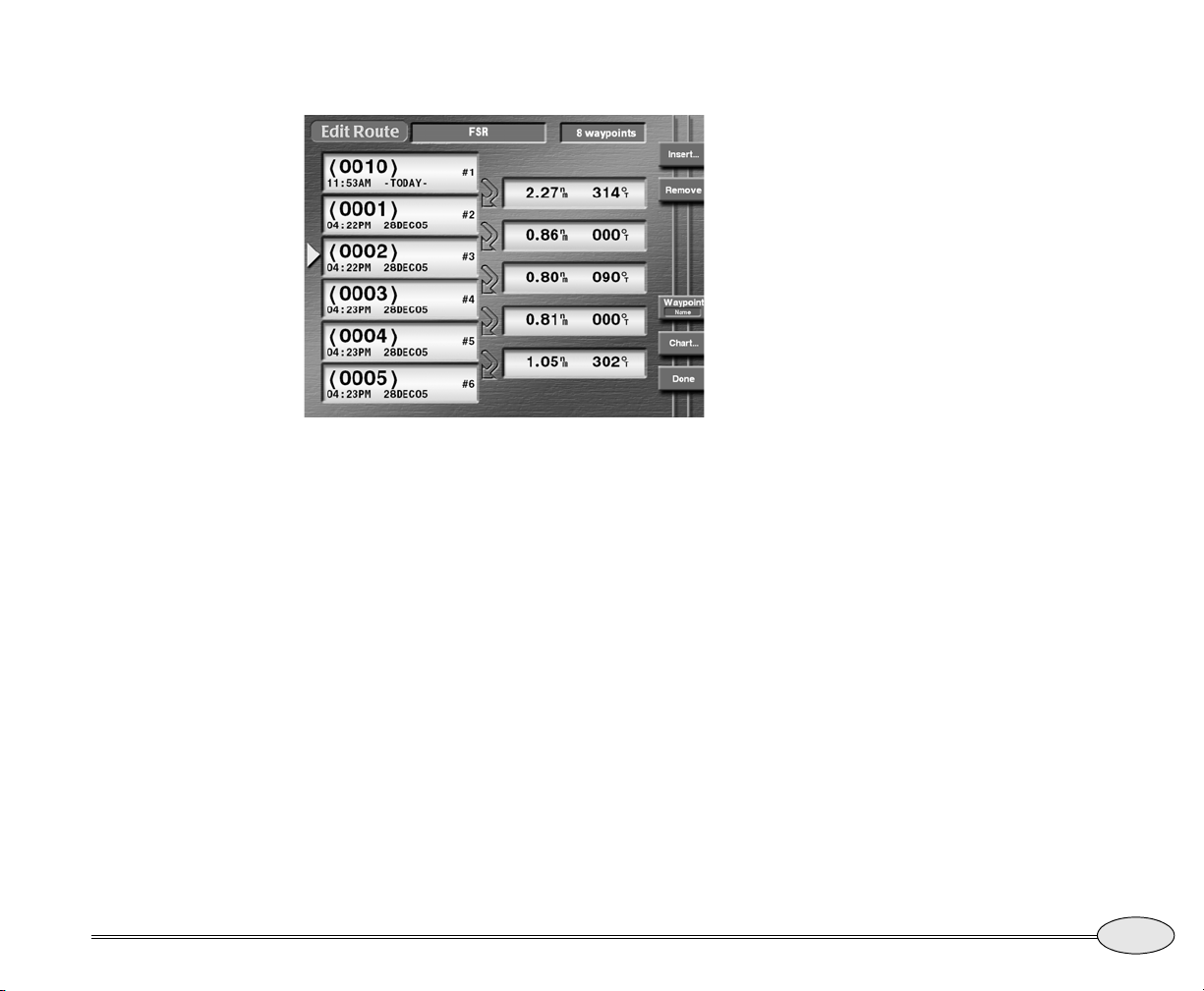
page 76, you can add or remove waypoints
using the waypoints list as follows:
Editing a route using the waypoints list
Removing waypoints from a route
1. Press the cursor pad to move the left-hand
pointer directly onto the waypoint you want to
remove.
2. Press
3. Press ENTER.
Remove.
Erasing an entire route
To erase a route:
1. On the Routes screen, press the CURSOR
PAD to select the route you want to erase.
2. Press
3. Press ENTER.
Erase.
Reference Manual Revision B
Adding waypoints to a route
1. Press the cursor pad to move the pointer at
the left side of the screen to the spot in
between two existing waypoints where you
want to insert a new waypoint.
(To add a waypoint to the beginning of the
route, be sure to position the pointer above
the first waypoint, not right onto it.)
2. Press Insert to display the Select waypt
screen that lists all your stored waypoints. To
switch between the local and alpha lists,
press
Next view.
Note: you can’t add an avoidance point to a
route.
3. Move the cursor to select the desired waypoint, then press ENTER to add the waypoint
to the route.
Editing a route you’re navigating along
When you follow a route, the route’s
waypoints are copied to the navplan for
safekeeping. The navplan is displayed on
most chart screens and on the
screen.
If you change a route you’re navigating
along, the 972 stores the changes, but they
won’t appear in the navplan you’re
following. To activate these changes in
your current navigation, you must start
following the route again.
If you edit the coordinates of a waypoint
directly in the navplan, you’ll receive a
Reference section 5 — Creating waypoints and routes
Navlog
Editing a route
79
Page 84
warning, as this might result in an unsafe
path. You cannot erase a waypoint that is
Transferring waypoints/routes to other units
Networked 972’s automatically share data.
This section only applies to transferring data
to or from the older Northstar units.
The 972’s import/export function lets you
transfer all waypoints and routes between a
972 and a Northstar 941, 951, 952, 957,
958, or 6000i.
in a route or the navplan; it must be
removed from the route first.
on an older unit to perform the transfer,
the instructions may be slightly different.
Be sure to choose the right function for
what you want to do: import waypoints
and routes from the second unit, or export
waypoints and routes to the second unit.
80
NOTE:
To import or export waypoints and routes to
and from older Northstar units, these older
units must contain software version 3.12 or
higher. To obtain any necessary upgrades,
please see your authorized Northstar
dealer.
You can perform the transfer from either
unit. The other unit can remain in normal
operation, including the displaying of
different screens, as long as you do not edit
any of its waypoints or routes during the
transfer. It is preferable to stop navigating
on the receiving unit by pressing
Navlog, and then Stop.
The unit you operate to perform the
transfer is called the “control unit.” The
instructions here apply to operating the
972; if you choose to operate the controls
Reference section 5 — Creating waypoints and routes
Transferring waypoints/routes to other units
STEER,
Connecting the two units
The two units must be properly connected
with the correct cabling and port settings.
For interfacing information, contact your
authorized Northstar dealer. To enable
transfers on the 972, go to the
screen, change the
and turn the unit off and then on.
Aux Port to “D/B XFER,”
Port Setup
Transferring waypoints and routes
When you transfer waypoints, the entire
contents of one unit’s database are moved
into the other. They will be added to the
waypoints and routes already in the
receiving unit. If any exact waypoint or
route name matches exist, the waypoints
or routes from one unit will overwrite the
waypoints or routes already in the other.
Northstar 972
Page 85
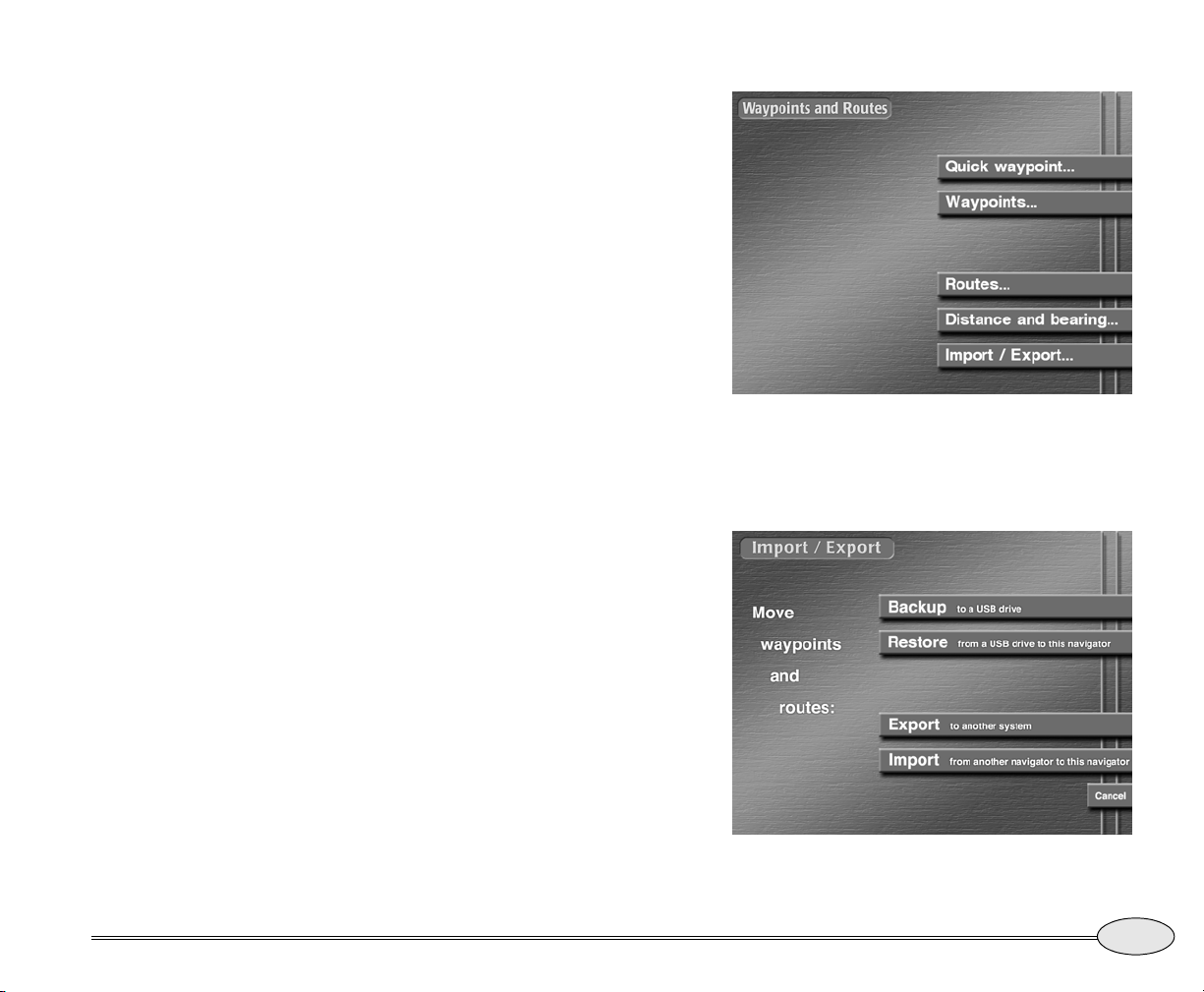
NOTE:
If you press any function key on the control
unit during the transfer, the message
“Transfer aborted by key hit” will be
displayed, and the process will be aborted.
The control unit will then display the
requested function. You can press any key
on the second unit, however, without
interrupting the transfer process.
To intentionally stop the transfer at any time,
press the
display the message “
key hit
up to that point are in the receiving unit (be
aware that routes may not contain all of their
waypoints due to the transfer interruption).
Press the
entire transfer process from the beginning.
1. Choose the unit you’d like to use as the
control unit. The instructions below are for a
972.
Remember: You can use either of the two
units because both units are capable of
importing or exporting waypoints and
routes. Make sure the second unit is on.
2. At the control unit, press
Stop key. The control unit will
Transfer aborted by
.” Waypoints and routes transferred
Start key again to restart the
WAYPTS/ROUTES
3. Press Import/Export.
Waypoints and routes screen
4. Decide whether you want to import waypoints
into the control unit, or export them to the second unit.
.
Reference Manual Revision B
Import/Export screen
Reference section 5 — Creating waypoints and routes
Transferring waypoints/routes to other units
81
Page 86
5. Press Import or Export to display the
import
or EXPORT data screen.
The status bar in the center of the screen
displays the message “R
to show that the transfer is ready to start.
6. Before transferring, you can check the communication link between the two units by
pressing
7. To move waypoints and routes in the direction
you’ve chosen, press
Test comm.
The status bar should display the message
“R
emote link ok.”
The status bar displays the message
“Transferring” and shows the number of
waypoints and routes already transmitted
against the total number. The progress bar,
located below the status bar, graphically
displays the percentage completed.
If there’s a problem with the transfer process, the following messages may appear:
If the second unit is not ready, the control
unit displays “C
eady to transfer”
Start.
ouldn’t get remote
waypt/route count” or “Transfer
aborted by communication timeout”
and the status-bar message “Communication error.
If the sending unit doesn’t have any waypoints and routes, the control unit displays
the dialog-box message “N
routes to transfer”
message “N
If the receiving unit is completely full of
waypoints and routes with no more room
available, the master unit displays the dialog-box message
database full
”
o waypts or
and the status-bar
o transfer done.”
“Status error [002]
.”
8. If the transfer is successful, the control unit’s
status bar displays the message “T
complete
You can now press any key to resume normal operations.
.”
ransfer
Notes on waypoint transfer
• The user should stop navigating when
performing an import on the 972. If the
transfer is not initiated from the 972, it
will allow the transfer, but cause an
error if any of the waypoints in the
active route are uploaded.
• Importing from a 961/962 is hidden. If
the “96Xexprt.txt” file is found on any
of the removable media, the import
function uses that file for transfer.
• Imported waypoints named *SAVEDnn*
are converted to (00nn)
• Imported waypoints named (coord) are
converted to COORD
• All unrecognizable characters are
converted to a space
• Imported waypoints are truncated to 6
characters, and a sequential numeric
digit is added to the end to make the
imported waypoint unique.
82
Reference section 5 — Creating waypoints and routes
Transferring waypoints/routes to other units
Northstar 972
Page 87
Transferring waypoints to and from a PC
If you’ve stored many waypoints or routes
in the 972, or if these waypoints are the
only record you have of these important
locations, you may want to keep a separate
copy on your Personal Computer.
You can transfer waypoints and routes to
your PC using Northstar’s loader cable
(part number 1100-LC) and the included
PC software. Using available third-party
software, you can copy, edit or plot your
waypoints and routes. Most importantly,
you can reload them from your PC into
your 972 if they’re accidentally erased or
lost due to equipment failure. For transfer
software and instructions, and cable
ordering information, contact your authorized Northstar dealer.
Reference Manual Revision B
Reference section 5 — Creating waypoints and routes
Transferring waypoints to and from a PC
83
Page 88
84
Reference section 5 — Creating waypoints and routes
Transferring waypoints to and from a PC
Northstar 972
Page 89
Reference section 6
Radar
How radar works . . . . . . . . . . . . . . . . . . . . . . . . . . . . . . . . . . . . 87
Turning the radar transmitter on and off . . . . . . . . . . . . . . . 87
Displaying radar. . . . . . . . . . . . . . . . . . . . . . . . . . . . . . . . . . . . . 87
Using the radar’s main menu keys . . . . . . . . . . . . . . . . . . . . . 88
Overlaying radar on the chart . . . . . . . . . . . . . . . . . . . . . . . . . 90
Changing radar scale and rotation . . . . . . . . . . . . . . . . . . . . . 90
Range rings . . . . . . . . . . . . . . . . . . . . . . . . . . . . . . . . . . . . . . . . . 91
Using the Adjustment keys. . . . . . . . . . . . . . . . . . . . . . . . . . . . 91
Using the Markers keys. . . . . . . . . . . . . . . . . . . . . . . . . . . . . . . 94
Reference Manual Revision B
Radar cursor. . . . . . . . . . . . . . . . . . . . . . . . . . . . . . . . . . . . . . . .
MARPA targets . . . . . . . . . . . . . . . . . . . . . . . . . . . . . . . . . . . . . . 96
96
This chapter first describes radar briefly, and then explains how to display, control, and
adjust the 972’s radar.
85
Page 90
86
Reference section 6 — Radar
Transferring waypoints to and from a PC
Northstar 972
Page 91
How radar works
The word “radar” is an acronym for “Radio
D
etecting and Ranging.” A radio transmitter sends out a very short microwave
pulse, and then a receiver listens for that
signal’s echo when it’s bounced back from
a target in its path. Targets, which may be
other boats or ships, navigational markers,
flocks of birds, or land masses, are
displayed on the 972’s screen. By knowing
Turning the radar transmitter on and off
Each time you turn on the Northstar 972,
the radar transmitter must be turned on
separately, as a safety feature.
To turn the transmitter on or off:
Displaying radar
how long it takes for a signal to return, the
distance to a target can be determined. As
the radar antenna scans through a
360-degree rotation, it shows the target’s
location relative to your position. By
watching repeated scans of a target, such
as another vessel, you can see how that
target is moving.
1. Press RADAR to display the radar screen.
2. Press
Transmit so it indicates On or
Standby, as desired.
Reference Manual Revision B
The radar image includes:
• a compass rose to show the direction of
true or magnetic north
• a gray heading line. This line indicates
your heading, not
Course-Over-Ground, and can be used
to compare the radar presentation with
the view in front of the vessel.
• in the upper left corner, the transmit
status (
and the current radar scale (Range
indicates the distance from the center
to the largest range ring, and RR
indicates the spacing between the
range rings)
• in the upper right corner, pulse length,
speed setting, rotation mode and Main
Bang Suppression (MBS)
Transmit on or Transmit standby),
Reference section 6 — Radar
How radar works
87
Page 92
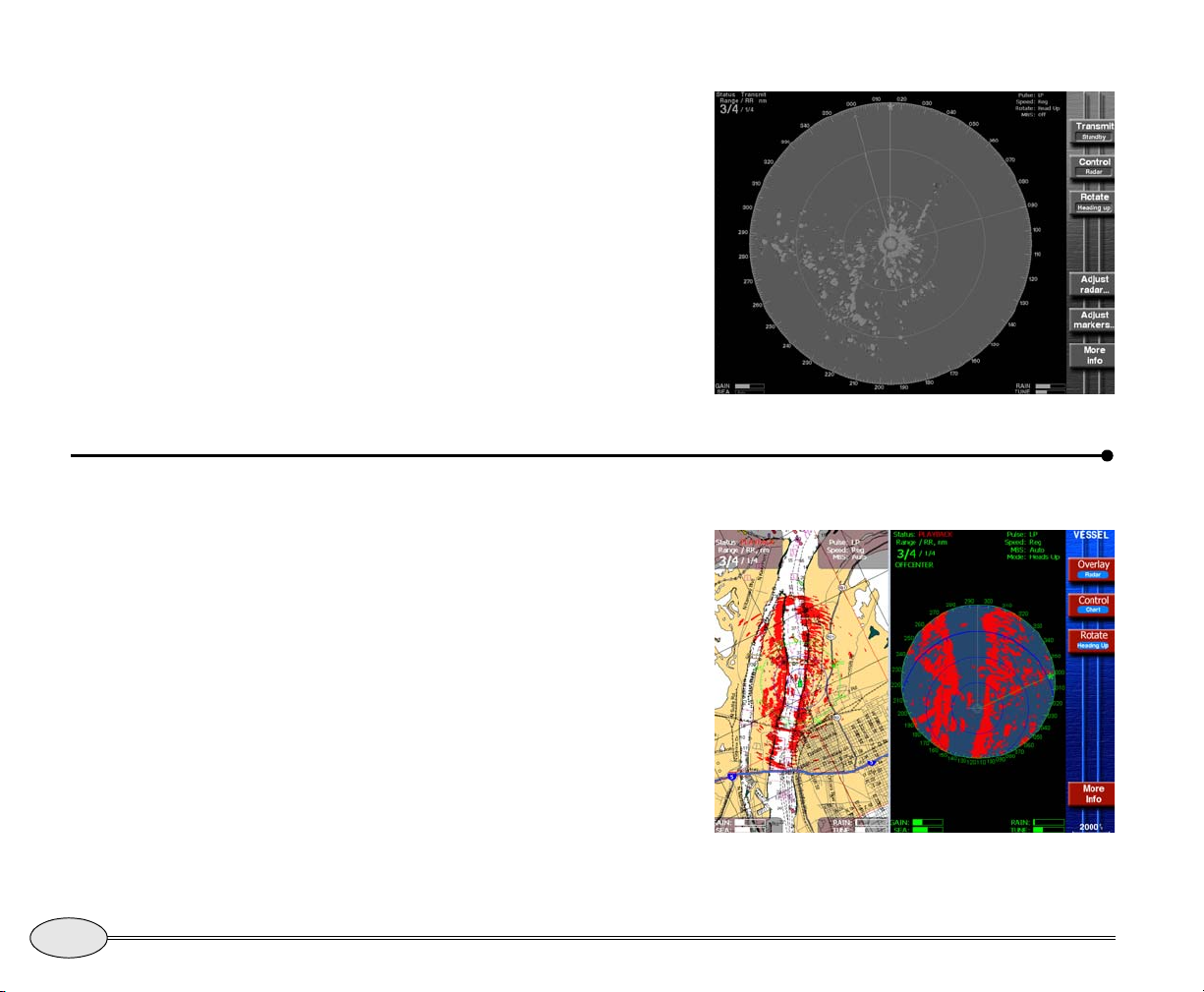
• in the lower right corner, rain clutter
and tuning indicators
• in the lower left corner, gain and sea
clutter indicators
For information about rotating and scaling
the radar, see Changing radar scale and
rotation, starting on page 90.
A demo mode for radar can be activated
from the
Chart Options screen. Press Demo
control and then Radar demo. The radar
demo position is located in the Fort
Lauderdale area.
Using the radar’s main menu keys
The radar’s main menu keys allow you to:
• turn the transmitter on or off
• switch control between the radar and
chart (if the chart is also displayed)
• rotate the radar image
• access the radar adjustments
• access the radar markers
• show more navigation information on
the info bar at the bottom of the screen
Radar screen
88
Reference section 6 — Radar
Using the radar’s main menu keys
Radar screen (split)
Northstar 972
Page 93
Transmitter control
Using the radar markers
When the radar image is displayed
full-screen by pressing the
menu key allows you to set the radar transmitter to
Standby or On.
RADAR key, a
Controlling radar
In order to control the radar from the
menu keys, the Control key (if displayed)
must indicate
If necessary, press the Control key repeatedly until it indicates
Radar.
Radar.
Rotating the radar image
Press Rotate repeatedly to choose the
screen rotation. You can choose north up,
course-up, heading-up, or leg-up. For more
information, see Changing radar scale and
rotation, on page 90.
Adjusting the radar
Press the Adjust radar… key to access
several pages of radar adjustments. For
more information about using these keys,
see Using the Adjustment keys, on page 91.
Press Adjust Markers… to display the
controls for the 972’s electronic bearing
line (EBL), variable range marker (VRM),
and guard zone. For more information
about using these keys, see Using the
Markers keys, starting on page 94.
Viewing more info
Press More info to display an “info bar” at
the bottom of the screen. Each additional
press of More info shows the following
information:
• your vessel’s present
Speed-Over-Ground (SOG),
Course-Over-Ground (COG), and
heading (HDG)
• your vessel’s distance (dist) and bearing
(brg) to the current waypoint, if any,
along with a steering indicator
• your vessel’s position in lat/lon (or TDs,
if enabled)
• tide and current information
Reference Manual Revision B
Reference section 6 — Radar
Using the radar’s main menu keys
89
Page 94
Overlaying radar on the chart
To overlay radar onto the chart, press
CHART to switch to the chart screen, then
press Overlay to display
blue box.
Radar can be displayed on the main radar
screen, or as an overlay on the chart
Radar in the key’s
Changing radar scale and rotation
To use radar features when radar is
overlaid on the chart or displayed as a split
screen, be sure to press Control if necessary so that the button indicates
Changing the scale
To change the radar’s scale, press the IN
key to zoom in (smaller area, more detail)
or the
less detail).
Using zoom on a split screen
If there’s no radar overlay on the chart, the
chart and radar are scaled separately.
Zooming in on the chart, for example, has
no effect on the radar’s scale. If the Control
key indicates
OUT key to zoom out (wider area,
Radar, you’re zooming the
Radar
screen, or as part of a split screen. All radar
functions are controlled in the same way,
regardless of how radar is displayed. Just
press the Control key so that it displays
Radar.
radar; if it indicates
the chart.
However, if the radar overlay is turned on,
the chart and radar scales are locked
together. When you zoom in on the chart,
radar scale changes to match the chart.
Chart, you’re zooming
Rotating the radar image
To rotate the radar image, press the
ROTATE key repeatedly until it indicates
the rotation you want. You have the same
options as for a
Course Up, Leg Up or Heading Up (see
Rotating the chart, starting on page 31).
The rotation of the chart and the rotation
of the radar interact under certain circumstances, as described in the table below. If
the Control key indicates
Chart screen: North Up,
Radar, you’re
90
Reference section 6 — Radar
Overlaying radar on the chart
Northstar 972
Page 95
rotating the radar; if it indicates Chart,
you’re rotating the chart.
Range rings
Range rings are concentric circles around
your vessel that can be used to measure
Using the Adjustment keys
distance from your vessel. The spacing of
the range rings is shown in the upper
left-hand corner of the radar image (identified by “
RR.”
Range rings can be turned off when they
are not needed.
Press Adjust radar… to display a menu
accessing several pages of radar adjustments. Most of these adjustments
correspond to conventional radar adjustments and are used in the same way. All
settings are retained while the system is
turned off.
The adjustment pages are:
• Image
• Advanced settings
• Presets
• Setup
Using the keys
A radar menu key on these screens must
be activated by pressing it once to change
the key from blue to red. (Any key that is
red is active and will respond immediately.
A blue key must first be pressed to activate
it.)
For keys with an
Auto and Manual setting,
press the menu a second time to change
this setting.
To enter a number, use the keypad to enter
the digits or use the cursor pad to step the
digits up or down.
To make an adjustment to the radar (such
as rain clutter, or gain, etc.), use the
following procedure:
1. Press the key (such as Gain) to activate it
(the key changes from blue to red).
2. Press the key again, if necessary to select
Auto or Manual.
3. If a numerical value appears, you can change
it by:
•
pressing the cursor pad up and
down (changes affect the display
Reference Manual Revision B
Reference section 6 — Radar
Using the Adjustment keys
91
Page 96
immediately after the cursor pad is
released), or
• using the numeric keys on the
keypad to enter the value
Image adjustments
Press the keys to adjust the gain, sea
clutter, rain clutter, or interference
rejection.
When pressed, the keys turns red to
indicate it is active and its value can be
adjusted.
Range Rider is a Northstar exclusive feature,
strongly recommended when manual
settings are required. The user can freely
make any needed gain and clutter adjustments, and these settings are
“remembered” for each range. When the
range is selected again, the last-used gain
and clutter settings for that range is reapplied.
Range Rider can be selected on the
Radar Options screen.
Gain controls the strength of all echoes,
and should be adjusted for a pleasing and
useful image. Higher values display
brighter echoes.
Gain can be set to automatic or manual
mode. Press the activated
switch modes. The gain setting can be
entered on the keypad or by using the
cursor pad. Manual settings range from 0
Gain key to
to 99. Manual gain adjustments will be
different for each range scale. Longer
ranges generally require more gain.
If speckling appears on the screen, you
may wish to decrease the gain a bit or
increase the sea clutter setting.
Sea Clutter controls the strength of the
clutter echoes returned from the ocean
surface. Higher values suppress more
clutter.
Sea Clutter can be set to automatic or
manual mode. Press the activated
clutter
key to switch modes. The sea clutter
Sea
setting can be entered on the keypad or by
using the cursor pad. Manual settings
range from 0 to 99.
Rain Clutter controls the strength of the
clutter echoes returned from rain or fog.
Higher values suppress more clutter.
Press the activated
Rain clutter key to
switch modes. The rain clutter setting can
be entered on the keypad or by using the
cursor pad. Manual settings range from 0
to 99.
Interference rejection. Certain types of
interference (for example, from radars on
other vessels) can be lessened by using the
interference rejection filter. Select Off, 1
(low), 2 (medium), or 3 (high).
92
Reference section 6 — Radar
Using the Adjustment keys
Northstar 972
Page 97
Manual vs. automatic settings
Speed
When gain or sea clutter is in manual
mode, the same setting is applied at all
directions from the vessel. In automatic
mode, settings are calculated scan line by
scan line. This provides the advantage that
the settings can be optimized for each
direction. For example, with a breeze, sea
clutter is typically stronger when looking
into the wind that when looking away from
it. The radar can automatically suppress
more sea clutter where it is needed, and
allow more signal to be displayed in areas
with less clutter return.
Advanced settings
Press the following keys to adjust the pulse
length, signal expansion, speed and
position offset.
Pulse
Select Long for better penetration through
rain and fog. Select Short for better
discrimination of small targets.
Expand
Select On to make small echoes appear
larger. Select Off for normal operation.
Select Normal for normal antenna rotation
speed (24 r.p.m). Select Fast for quicker
rotation (48 r.p.m.)
NOTE
For 4kW Dome radars, you must switch the
radar to Standby mode and then back to
Transmit when this setting is changed.
For all other radars, this feature is only
available on 24VDC systems.
Offset
Select Center to position the vessel in the
center of the screen. Select Look ahead to
display more area in front of the vessel.
Presets
There are two types of presets — for automatic and for manual settings.
Manual presets
To set the manual presets, first return to
the Image page, described above, and set
Gain and Sea Clutter to
These presets set the minimum value for
the manual settings, so that the manual
adjustment covers the entire useful range
Manual.
Reference Manual Revision B
Set the control (for example, gain) to a
mid-range value (such as 30), and then
Reference section 6 — Radar
Using the Adjustment keys
93
Page 98
adjust the gain preset to produce a
good-looking image.
Automatic presets
To set the automatic presets, first return to
the Image page described above, and set
Gain and Sea Clutter to
Gain preset
Set this control for a pleasing looking
image. The unit will attempt to maintain
this appearance.
Sea preset
Set this control for a pleasing looking
image. The unit will attempt to maintain
this appearance.
Sea clutter preset can be adjusted for
mode (for when the range is set to less
than 1nm, or for
range is set to greater than 1 mile).
auto mode (for when the
Automatic.
harbor
Auto tuning
STC curve
The STC curve controls how the sea clutter
function decreases the gain near the vessel.
Setup…
See the radar installation manual (P/N
GMEKRadIM) for using these controls.
Under normal circumstances these controls
will not be used for day-to-day operation.
They are set once during the initial installation and should not be changed except
during maintenance of the system.
Trigger delay
Heading calib
Park angle
Using the Markers keys
Press Adjust Markers to display controls
for the 972’s electronic bearing line (EBL),
variable range marker (VRM), and guard
zone.
94
Reference section 6 — Radar
Using the Markers keys
Press EBL, VRM or GuardZone to access
that function. Press Visibility to make the
selected function visible or invisible.
When finished, press Return to return to
the main radar menu keys. All settings are
retained while the system is turned off.
Northstar 972
Page 99
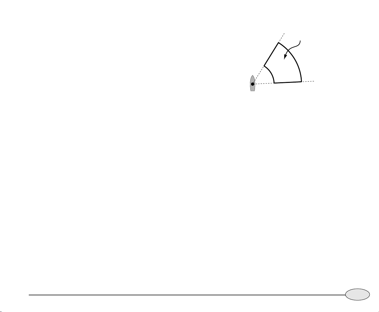
Electronic Bearing Line (EBL)
The Electronic Bearing Line is a marker
that you can place on top of the radar
image to aid in navigation and to keep
track of your surroundings.
Use the cursor pad to move the EBL
around your position to measure the
bearing to any object on the screen.
Variable Range Marker (VRM)
The Variable Range Marker is displayed as
a circle around your vessel. Use the cursor
pad to make the circle bigger or smaller.
The distance to the marker is displayed in
the lower left corner of the screen.
Guard zone
Press the Guard Zone menu key to control
this feature. Echoes detected inside the
guard zone will cause an alarm.
The guard zone is bounded by red lines —
an inner and an outer arc centered on the
vessel, and two straight lines extending
outward from the vessel. The interior of
the guard zone is yellow.
Guard Zone
Figure 4: Guard zone
Press the following keys to adjust each
guard zone.
Press Visibility to show or hide the guard
zone. When the zone is hidden, it doesn’t
alarm.
To adjust the position of the guard zone,
press GuardZone (if necessary) so that it
displays
the position.
To adjust the size of the guard zone, press
GuardZone (if necessary) so that it displays
Size. Use the cursor pad to set its size.
Position. Use the cursor pad to set
Reference Manual Revision B
You can turn visibility of the zone on or
off, and change its boundaries.
Reference section 6 — Radar
Using the Markers keys
95
Page 100
Radar cursor
MARPA targets
If you press the cursor pad while on the
radar screen, a radar cursor is displayed.
You can move the cursor to any echo or
other point on the screen and read the
The Miniature Automatic Radar Plotting
Aid (MARPA) target tracking system allows
you to designate displayed echoes as
targets, which will be tracked automatically as they move. Each target’s speed,
course-over-ground, closest point of
approach, etc. are calculated and displayed.
Targets are displayed on the radar image
with special symbols indicating their acquisition status.
You can control how much data is
displayed for each target.
MARPA is used primarily for collision
avoidance in larger ships at ranges from
about 2 to 8 nautical miles, and in smaller
ships at ranges between 1/2 and 4 nautical
miles.
distance and bearing to it in the lower right
corner of the screen.
Press Vessel to remove the radar cursor
when done.
How does MARPA work?
MARPA works by continuously assessing a
target you have designated. As the vessel
pitches and rolls with the sea, the radar’s
view, the target’s shape and size, and the
ship’s heading will all vary. If you can’t see
the target on the radar, then the MARPA
feature can’t see it either.
The 972 has built-in intelligence that
compensates for all this variation and
makes every attempt to track MARPA
targets — even in difficult conditions.
A critical component in the operation of
the MARPA feature is your heading sensor.
The heading sensor provides MARPA with
critical information to correlate the radar
display with the ship’s heading. A poor
heading sensor can make MARPA a challenge even in good conditions.
96
Reference section 6 — Radar
Radar cursor
Northstar 972
 Loading...