


·.·ADVANTAGE
Technical
Manual
00464C
TABLE
OF
CONTENTS
Section
1
INTRODUCTION
1.1
1.2
1.3
1.4
2
ADVANTAGE
2.1
2.2
using
System
this
Description
Warranty
ADVANTAGE
OPERATION
Operating
2.1.1
2.1.2
2.1.3
System
2.2.1
Keyboard
Rear
Diskette
Startup
Standard
From
2.2.2
Alternate
From
2.2.3
Alternate
From A
2.2.4
Mini-Motor
Manual
Specifications
Cont~ols
Panel
Controls
Loading/Unloading
Startup
Drive
1
Startup
Drive
2
Startup
Serial
Startup
Port
-
Booting
-
Booting
Booting
-
Page
1-1
1-2
1-3
1-6
1-7
2-1
2-1
2-1
2-4
2-6
2-7'
2-7
2-8
2-8
2-8
2.3
Restarting
2.3.1
3
IMPLEMENTING
3.1
3.2
Microprocessor
Memory
3.2.1
3.2.2
3.3
Inter'rupts
3.3.1
3.3.2
3.4
Shared
The
System
Keyboard
ADVANTAGE
Reset
FEATURES
Control
Control
Memory
Memory
Maskable
Mapping
Parity
Interrupts
Non-Maskab1e
I/O
Interface
Interrupts
Registers
2-9
2-9
3-1
3-1
3-1
3-1
3-6
3-7
3-8
3-8
3-9
ADVANTAGE
i
TECHNICAL
MANUAL
TABLE
OF
CONTENTS
(continued)
Section
3.5.
3.6
3.7
Keyboard
3.5.1
3.5.2
3.5.3
3.5.4
3.5.5
3.5.6
3.5.7
3.5.8
Video
3.6.1
3.6.2
3.6.3
3.6.4
3.6.5
Floppy
3.7.1
3.7.2
3.7.3
3.7.4
3.7.5
3.7.6
3.7.7
3.7.8
Keyboard
Reset
Interrupt
Read
Character
Cursor
All
Auto
Display
Screen
Forming
Display
Screen
Video
Disk
Power-on
Motor
Drive
Seek
Sector
Read
Write
Floppy
Control
Keyboard
Lock
Caps
Repeat
Control
Mapping
Blanking
Driver
Drive
Enable
Selection
Selection
Data
Data
Disk
Reset
or
Enable
Polled
Overrun
Letters
and
Flag
Control
Initialization
Data
Symbols
Format
Page
3-16
3-16
3-17
3-17
3-19
3-19
3-12
3-21
3-21
3-22
3-23
3-25
3-27
3-27
3-27
3-31
3-34
3-34
3-34
3-34
3-35
3-36
3-37
3-39
ADVANTAGE
3.8
3.9
Hard
3.8.1
3.8.2
3.8.3
3.8.4
3.8.5
3.8.6
Disk
I/O
Head
Data
Format
Read
Write
Accessing
3.9.1
3.9.2
3.9.3
3.9.4
Reset
Board
Byte
Interrupt
Drive
Commands
Positioning
Format
Operation
Operations
Operation
The
I/O
Identification
Transfers
ii
Control
Boards
TECHNICAL
3-40
3-40
3-45
3-47
3-48
3-49
3-50
3-51
3-51
3-51
3-53
3-53
MANUAL
TABLE
OF
CONTENTS
(continued)
Section
3.10
3.11
3.12
SIO
Board
3.10.1
3.10.2
3.10.3
3.10.4
3.10.5
3.10.6
3.10.7
3.10.8
PIO
Board
3.11.1
3.11.2
3.11.3
3.11.4
3.11.5
3.11.6
3.11.7
Speaker
Reset
Board
Data
Identification
Transfers
Control
Status
Interrupt
SIO
In
SIO
In
or
Asynchronous
Synchronous
Reset
Board
Data
Identification
Transfers
Control
Status
Interrupt
or
Programming
Control
Polled
Polled
Example
Mode
Mode
Page
3-54
3-54
3-54
3-55
3-55
3-57
3-58
3-58
3-66
3-72
3-72
3-73
3-73
3-73
3-74
3-75
3-77
3-77
3.13
4
THEORY
4.1
4.2
Bootstrap
3.13.1
3.13.2
3.12.3
OF
OPERATION
Main
4.1.1
4.1.2
4.1.3
4.1.4
PC
Central
Main
Boot
Auxiliary
Keyboard
4.1.5
4.1.6
Floppy
Dislay
4.1.7
4.1.8
4.1.9
Hard
Speaker
Voltage
Disk
Firmware
Startup
Boot
Boot
From
From
Board
RAM
PROM
I/O
Board
Controller
Disk
Serial
Processor
Processor
Disk
RAM
Controller
and
Interface
Circuit
Regulators
Board
Drive
Port
Video
and
Generator
3-78
3-78
3-79
3-82
4-1
4-1
4-4
4-15
4-18
4-18
4-22
4-25
4-36
4-41
4-41
4-44
ADVANTAGE
iii
TECHNICAL
MANUAL
TABLE
OF
CONTENTS
(continued)
Section
5
PREVENTIVE
5.1
5.2
5.3
6
DIAGNOSTICS
6.1
6.2
4.2.1
4.2.2
4.2.3
MAINTENANCE
Wear
and
Voltage
Voltage
and
Adjustment
The
Mini-Monitor
The
General
6.2.1
6.2.2
6.2.3
6.2.4
6.2.5
6.2.6
6.2.7
Track
Hard
Hard
and
Disk
Disk
Damage
Checks
and
Controlled
Diagnostic
Single
Floppy
Block
Disk
Executable
Video
SIO
Memory
Board
Keyboard
Display
Monitor
Sector
Controller
Drive
Inspection
Adjustment
Oscillator
Programs
Mode
Subsystem
Memory
Test
Test
Test
Test
Format
Test
Test
Page
4-44
4-44
4-55
5-1
5-2
5-3
Check
5-4
6-1
6-2
6-4
6-4
6-6
6-8
6-11
6-12
6-13
6-22
6.3
TROUBLESHOOTING
7
7.1
7.2
7.3
Hard
Tools
Troubleshooting
7.2.1
Assembly
7.3.1
7.3.2
7.3.3
7.3.4
Disk
Diagnostic
and
Test
AND
REPAIR
Equipment
Troubleshooting
Replacement
Opening
and
Cabinet
Removing
Keyboard
Removing
PC
Main
Board
Removing
Disk
Drive
Procedures
Procedures
Chart
Procedures
Closing
and
Installing
and
Installing
and
Installing
6"';23
?,-l
7-1
7-2
7-2
7-15
ADVANTAGE
7-16
The
7-20
The
7-24
a
7-27
ADVANTAGE
iv
TECHNICAL
MANUAL
TABLE
OF
CONTENTS
(continued)
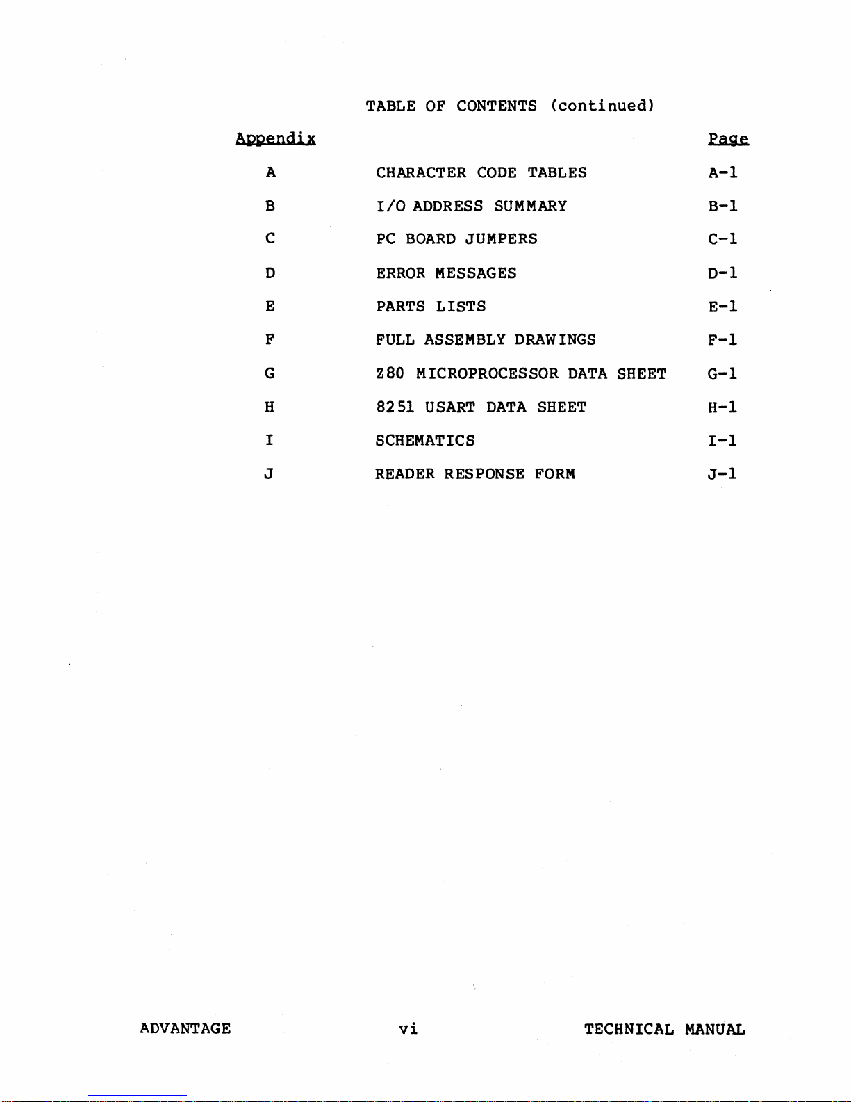
Aggendix
A
B
C
o
E
F
G
H
I
J
CHARACTER
IIO
ADDRESS
PC
BOARD
ERROR
PARTS
FULL
Z80
8251
MESSAGES
LISTS
ASSEMBLY
MICROPROCESSOR
USART
CODE
JUMPERS
SCHEMATICS
READER
RESPONSE
TABLES
SUMMARY
DRAWINGS
DATA
SHEET
FORM
DATA
SHEET
~
A-I
B-1
C-l
0-1
E-l
F-l
G-l
H-l
I-I
J-l
ADVANTAGE
vi
TECHNICAL
MANUAL
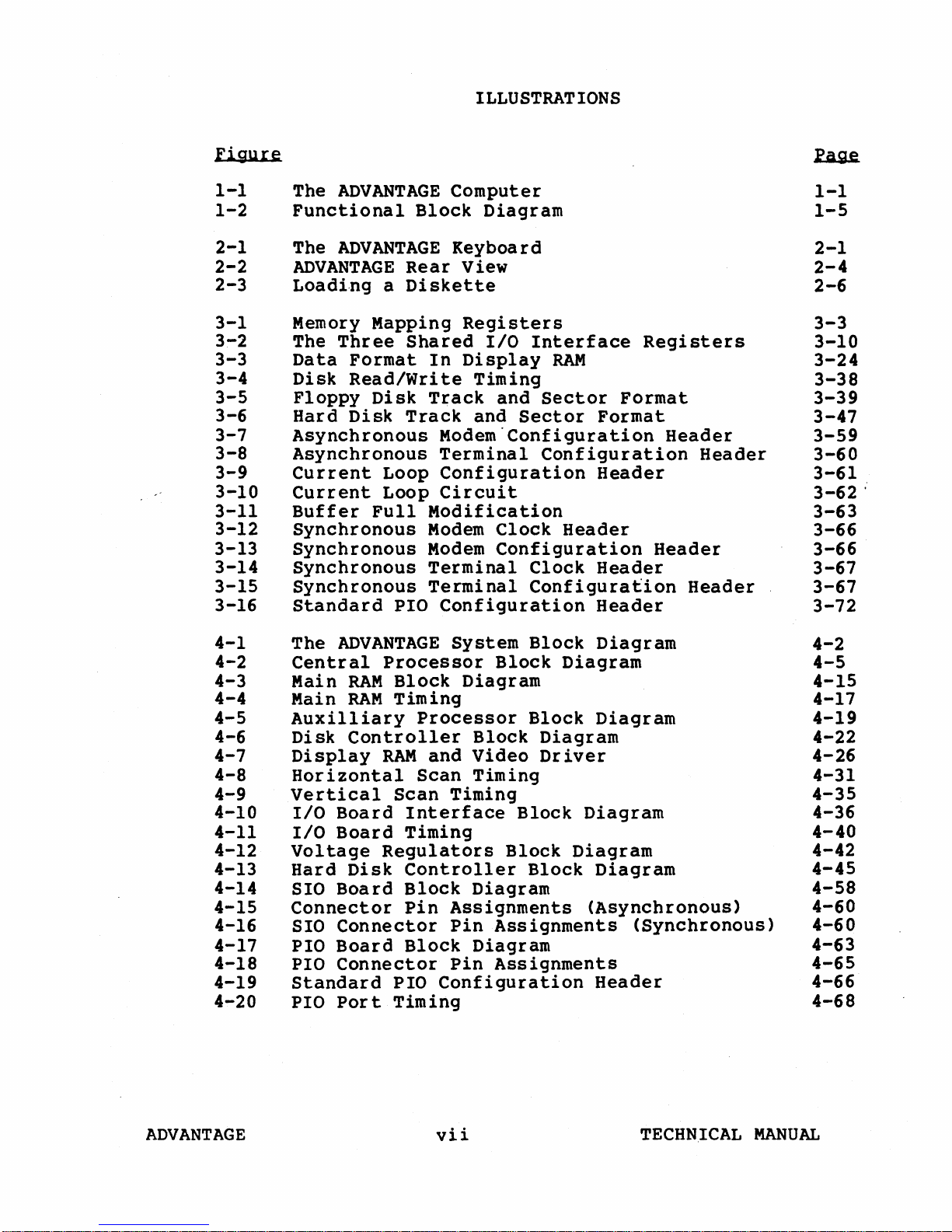
ILLUSTRATIONS
Figure
1-1
1-2
2-1
2-2
2-3
3-1
3-2
3-3
3-4
3-5
3-6
3-7
3-8
3-9
3-10
3-11
3-12
3-13
3-14
3-15
3-16
The
ADVANTAGE
Functional
The
ADVANTAGE
ADVANTAGE
Block
Rear
Computer
Keyboard
View
Loading a Diskette
Memory
The
Data
Disk
Floppy
Hard
Asynchronous
Asynchronous
Current
Current
Buffer
Synchronous
Synchronous
Synchronous
Synchronous
Standard
Mapping
Three
Shared
Format
Read/Write
Disk
Disk
Track
Loop
Loop
Full
PIO
Registers
In
Display
Timing
Track
and
Modem'Configuration
Terminal
Configuration
Circuit
Modification
Modem
Modem
Terminal
Terminal
Configuration
Diagram
I/O
Interface
RAM
and
Sector
Sector
Configuration
Clock
Header
Configuration
Clock
Configuration
Registers
Format
Format
Header
Header
Header
Header
Header
Header
Header
~
1-1
1-5
2-1
2-4
2-6
3-3
3-10
3-24
3-38
3-39
3-47
3-59
3-60
3-61
3-62
3-63
3-66
3-66
3-67
3-67
3-72
'
4-1
4-2
4-3
4-4
4-5
4-6
4-7
4-8
4-9
4-10
4-11
4-12
4-13
4-14
4-15
4-16
4-17
4-18
4-19
4-20
The
ADVANTAGE
Central
Main
Main
Processor
RAM
RAM
Auxilliary
Disk
Display
Controller
RAM
Horizontal
Vertical
I/O
Board
I/O
Board
Voltage
Hard
SIO
Regulators
Disk
Board
Connector
SIO
Connector
PIO
Board
PIO
Connector
Standard
PIO
Port
System
Block
Diagram
Timing
Processor
and
Video
Scan
Scan
Timing
Timing
Interface
Timing
Controller
Block
Pin
Diagram
Assignments
Pin
Block
Diagram
Pin
PIO
Configuration
Timing
Block
Block
Diagram
Block
Block
Diagram
Driver
Block
Block
Block
Assignments
Assignments
Diagram
Diagram
Diagram
Diagram
Diagram
(Asynchronous)
(Synchronous)
Header
4-2
4-5
4-15
4-17
4-19
4-22
4-26
4-31
4-35
4-36
4-40
4-42
4-45
4-58
4-60
4-60
4-63
4-65
4-66
4-68
ADVANTAGE
vii
TECHNICAL
MANUAL
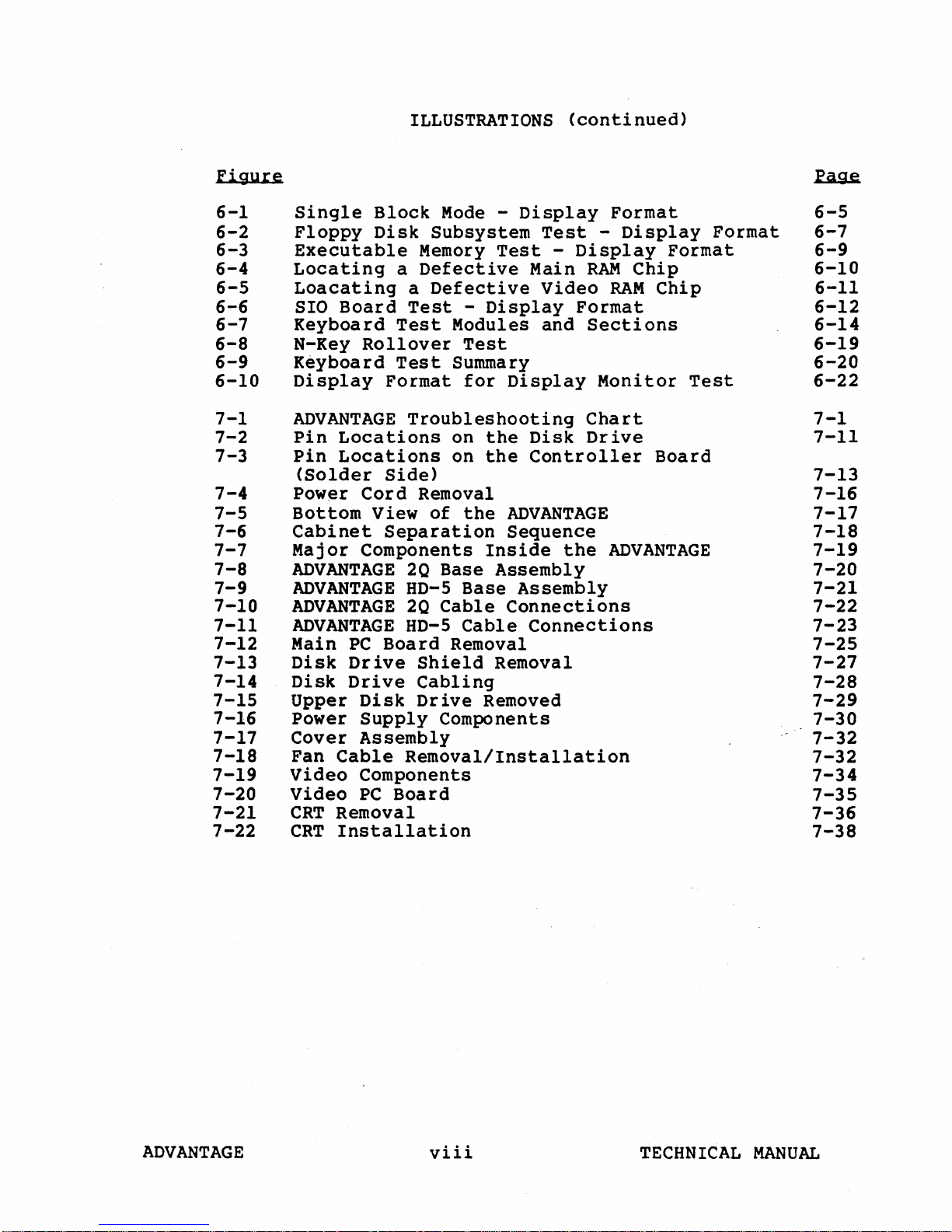
ILLUSTRATIONS
(continued)
Figure
6-1
6-2
6-3
6-4
6-5
6-6
6-7
6-8
6-9
6-10
7-1
7-2
7-3
7-4
7-5
7-6
7-7
7-8
7-9
7-10
7-11
7-12
7-13
7-14
7-15
7-16
7-17
7-18
7-19
7-20
7-21
7-22
Single
Floppy
Block
Disk
Executable
Locating
a
Loacating
SIO
Board
Keyboard
N-Key
Keyboard
Display
Test
Rollover
Test
Format
ADVANTAGE
Pin
Locations
Pin
Locations
(Solder
Power
Bottom
Cabinet
Major
Side)
Cord
View
Separation
Components
ADVANTAGE
ADVANTAGE
ADVANTAGE
ADVANTAGE
Main
Disk
Disk
PC
Drive
Drive
Upper
Power
Cover
Fan
Cable
Video
Video
CRT
Removal
CRT
Installation
80-5
Board
Disk
Supply
Assembly
Removal/Installation
Components
PC
Board
Mode -Display
Subsystem
Memory
Defective
a
Defective
Test
-
Display
Test
Test
Main
Video
Modules and
Test
Summary
for
Display
Troubleshooting
on
the
Disk
on
the
Controller
Removal
of
the
ADVANTAGE
Sequence
Inside
20
Base
HD-5
20
Cable
Assembly
Base
Assembly
Connections
Cable
Connections
Removal
Shield
Removal
Cabling
Drive
Removed
Components
-
Display
RAM
Format
Sections
Chart
Drive
the
Format
-
Display
Format
Chip
RAM
Chip
Monitor
Test
Board
ADVANTAGE
Format
~
6-5
6-7
6-9
6-10
6-11
6-12
6-14
6-19
6-20
6-22
7-1
7-11
7-13
7-16
7-17
7-18
7-19
7-20
7-21
7-22
7-23
7-25
7-27
7-28
7-29
7-30
7-32
7-32
7-34
7-35
7-36
7-38
ADVANTAGE
viii
TECHNICAL
MANUAL
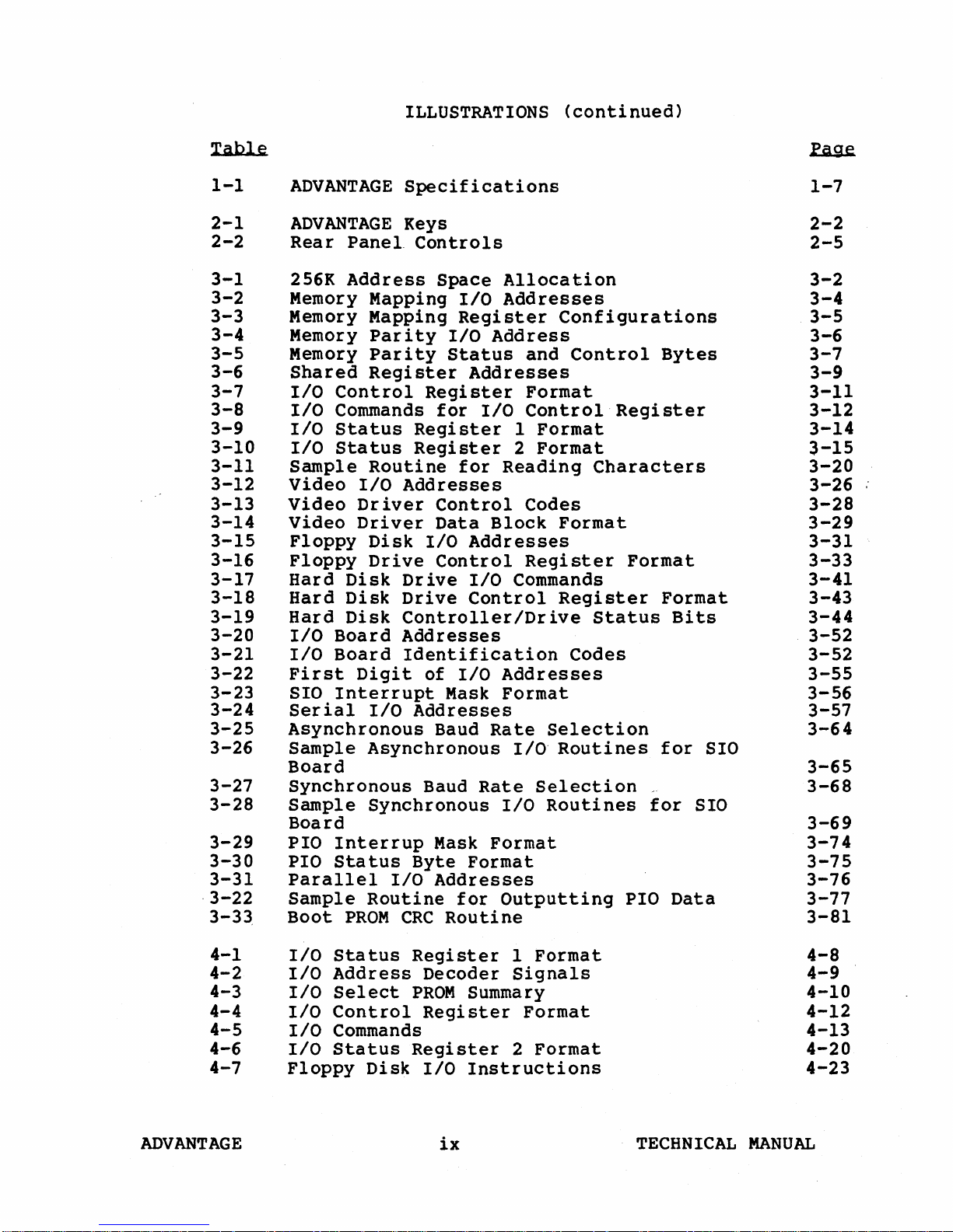
ILLUSTRATIONS
(continued)
Table
1-1
2-1
2-2
3-1
3-2
3-3
3-4
3-5
3-6
3-7
3-8
3-9
3-10
3-11
3-12
3-13
3-14
3-15
3-16
3-17
3-18
3-19
3-20
3-21
3-22
3-23
3-24
3-25
3-26
3-27
3-28
3-29
3-30
3-31
·3-22
3-33
ADVANTAGE
ADVANTAGE
Rear
256K
Panel.
Address
Specifications
Keys
Controls
Memory Mapping
Memory Mapping
Memory
Memory
Shared
I/O
I/O
I/O
I/O
Sample
Video
Video
Video
Floppy
Floppy
Hard
Hard
Hard
I/O
I/O
First
SIO
Serial
Asynchronous
Sample
Parity
Parity
Register
Control
Commands
Status
Status
Register
Register
Routine
I/O
Addresses
Driver
Driver
Disk
Drive
Disk
Disk
Disk
Board
Board
Drive
Drive
Controller/Drive
Addresses
Identification
Digit
Interrupt
I/O
Addresses
Asynchronous
Register
Control
Data
I/O
Control
of
Baud
Board
Synchronous
Sample
Synchronous
Baud
Board
PIO
Interrup
PIO
Status
Parallel
Sample
Boot
PROM
Routine
Mask
Byte
I/O
Addresses
CRC
Space
I/O
Register
I/O
Address
Status
Addresses
for
I/O
for
Block
Addresses
I/O
Control
I/O
Mask
Rate
Rate
Format
Format
for
Routine
Allocation
Addresses
Configurations
and
Control
Format
Control
1
Format
2
Format
Reading
Characters
Codes
Format
Register
Commands
Register
Status
Codes
Addresses
Format
Selection
I/O·
Routines
Selection
I/O
Routines
Outputting
Bytes
Register
Format
Format
Bits
for
for
PIO
Data
~
1-7
2-2
2-5
3-2
3-4
3-5
3-6
3-7
3-9
3-11
3-12
3-14
3-15
3-20
3-26
3-28
3-29
3-31
3-33
3-41
3-43
3-44
3-52
3-52
3-55
3-56
3-57
3-64
SID
3-65
3-68
SIO
3-69
3-74
3-75
3-76
3-77
3-81
4-1
4-2
4-3
4-4
4-5
4-6
4-7
I/O
I/O
I/O
I/O
I/O
I/O
Floppy
ADVANTAGE
Status
Register
Address
Select
PROM
Control
Commands
Status
Register
Disk
Decoder
Summary
Register
I/O
Instructions
ix
1
Format
Signals
Format
2
Format
TECHNICAL
4-8
4-9
4-10
4-12
4-13
4-20
4-23
MANUAL
Figure
ILLUSTRATIONS
(continued)
4-8
4-9
4-10
4-11
4-12
4-13
4-14
4-15
4-16
4-17
4-18
4-19
5-1
6-1
6-2
6-3
7-1
7-2
7-3
7-4
Floppy
HTIML
HTIMH
60
50
1/0
Hard
SIO
SIO
PIa
PIa
PIa
Disk
Horizontal
Horizontal
Hz
vertical
Hz
Vertical
Board
Disk
Board
Board
Board
status
Interrupt
Pin
Controller
I/O
1/0
1/0
Preventive
Mini-Monitor
Keyboard
Keyboard
Main
Main
Main
Driver
Test
Test
Board
Board
Board -Floppy
Status
Control
Register
Scan
Scan
Timing
Timing
Assignments
Instructions
Instructions
Instructions
Byte
Format
Mask
Format
Maintenance
Commands
Abbreviation
Control
Input
Video
Power
Interface
Disk
Signals
Format
PROM
PROM
PROM
PROM
Input/Output
Schedule
Codes
Keys
(Jll)
(J7)
Power
Sign~ls
(JI0)
4-24
4-28
4-29
4-33
4-34
4-38
4-46
4-61
4-62
4-67
4-68
4-69
5-1
6-3
6-16
6-21
7-6
7-6
7-10
7-14
ADVANTAGE
x
TECHNICAL
MANUAL
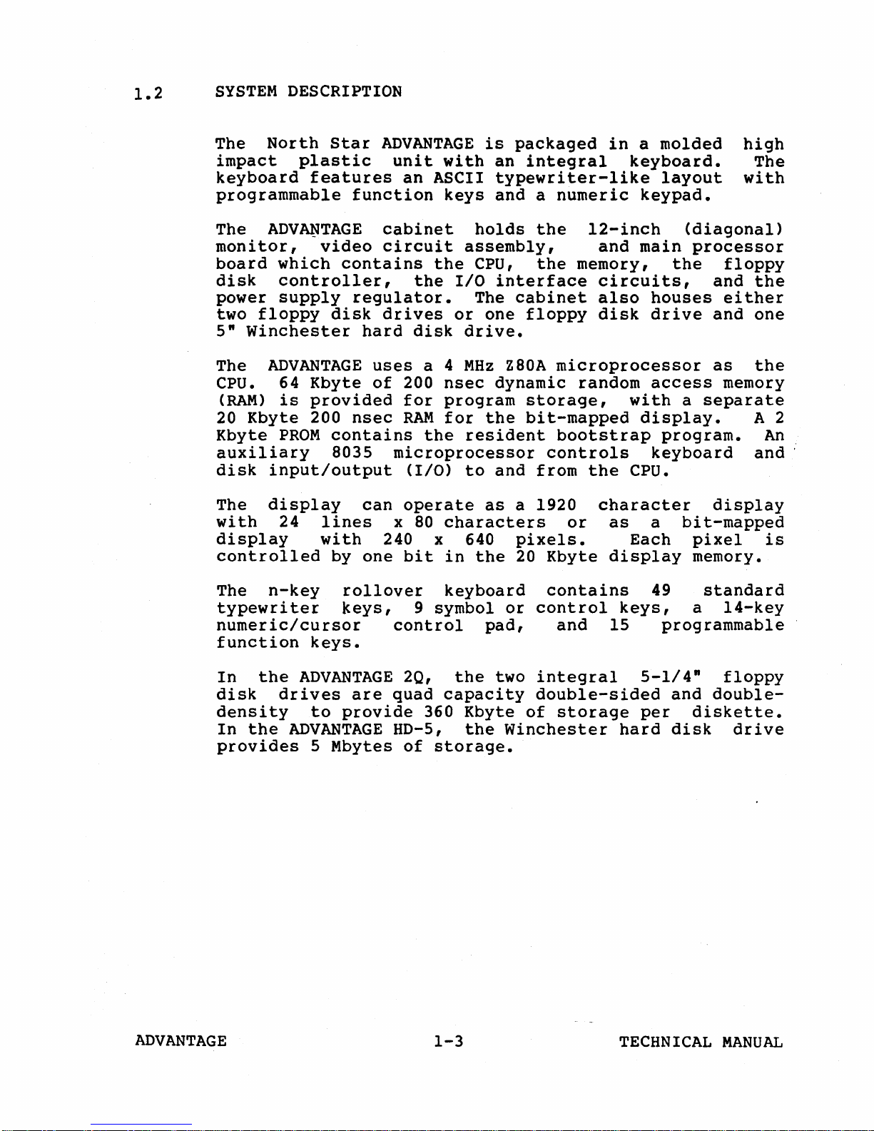
1.2
SYSTEM
DESCRIPTION
The
impact
keyboard
North
plastic
features
Star
programmable
The
monitor,
board
disk
power
two
5"
The
cpu.
(RAM)
20
Kbyte
ADV~TAGE
video
which
controller,
supply
floppy
Winchester
ADVANTAGE
64
Kbyte
is
provided
Kbyte
200
PROM
auxiliary
disk
The
with
display
input/output
display
24
lines
with
controlled
ADVANTAGE
unit
function
cabinet
circuit
contains
regulator.
disk
drives
hard
uses
of
nsec
contains
8035
microprocessor
can
x
240 x 640
by
one
with
an
ASCII
keys
the
the
I/O
or
disk
a 4
200
nsec
for
program
RAM
for
the
(I/O)
operate
80
characters
bit
in
is
packaged
an
integral
typewriter-like
and a numeric
holds
the
assembly,
CPU,
the
interface
The
cabinet
one
floppy
drive.
MHz
Z80A
microprocessor
dynamic
storage,
the
bit-mapped
resident
bootstrap
controls
to
and
from
as
a 1920
pixels.
the
20
Kbyte
in
l2-inch
and
memory,
circuits,
also
disk
random
the
character
or
as
display
a
molded
keyboard.
layout
keypad.
(diagonal)
main
processor
the
houses
drive
access
with
a
separate
display.
program.
keyboard
cpu.
a
bit-mapped
Each
pixel
memory.
high
The
with
floppy
and
the
either
and
one
as
the
memory
A 2
An
and:
display
is
The
n-key
typewriter
numeric/cursor
function
In
the
disk
density
In
the
provides
keys.
ADVANTAGE
drives
to
ADVANTAGE
5 Mbytes
rollover
keys,
control
are
quad
provide
HD-5,
keyboard
9 symbol
2Q,
the
capacity
360 Kbyte
the
of
storage.
contains
or
control
pad,
two
integral
double-sided
of
Winchester
and
15
storage
49
keys,
programmable
5-1/4"
and
per
hard
disk
standard
a
l4-key
floppy
double-
diskette.
drive
ADVANTAGE
1-3
TECHNICAL
MANUAL
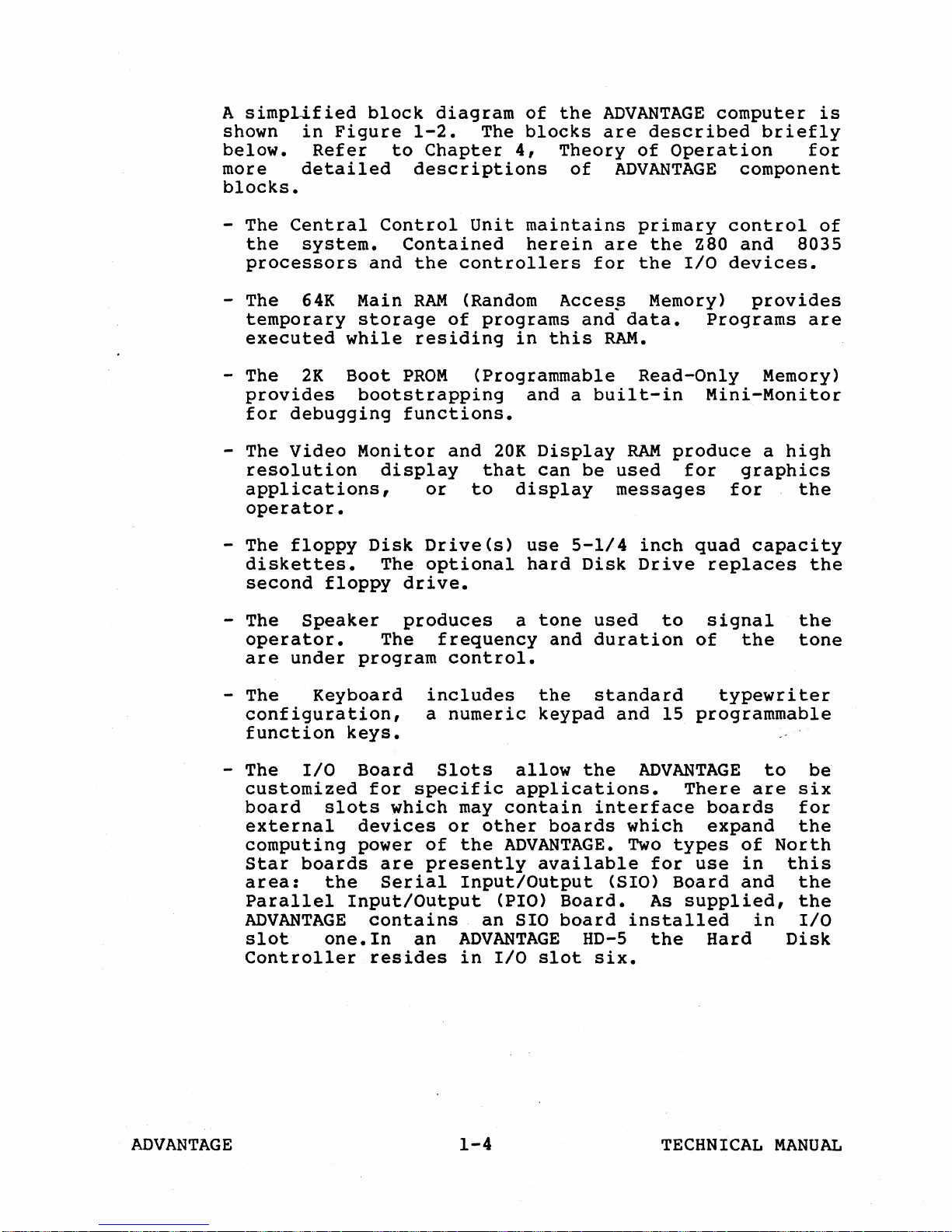
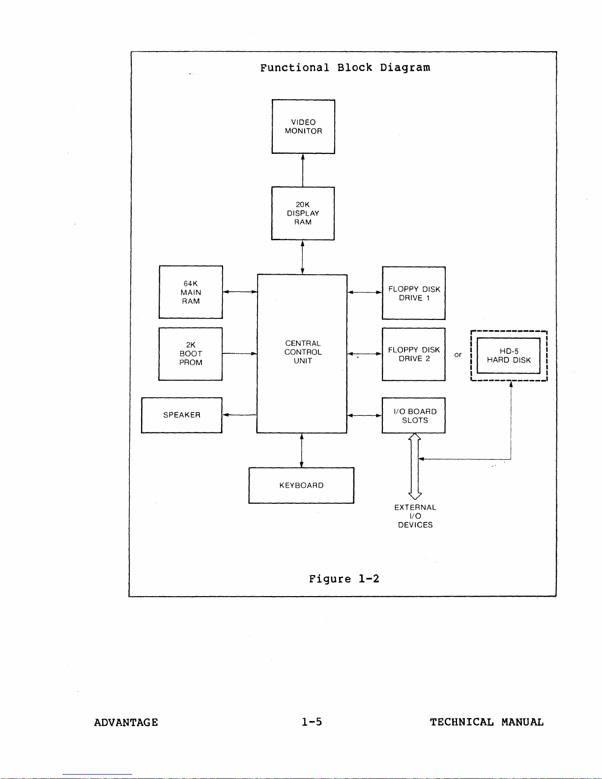
A
simplified
shown
below.
more
blocks.
in
Figure
Refer
detailed
block
1-2.
to
Chapter
descriptions
diagram
The
of
blocks
4,
the
ADVANTAGE
are
Theory
of
ADVANTAGE
described
of
Operation
computer
briefly
component
is
for
- The
the
Central
system.
processors
- The
64K
temporary
executed
- The
2K
provides
for
debugging
- The
Video
resolution
applications,
operator.
- The
floppy
diskettes.
second
- The
Speaker
operator.
are
under
Control
Contained
and
Main
storage
while
Boot
PROM
bootstrapping
functions.
Monitor
display
Disk
The
floppy
drive.
produces
The
program
Unit
the
controllers
RAM
(Random
of
residing
(Programmable
and
or
to
Drive(s)
optional
frequency
control.
maintains
herein
Accesp
programs
in
this
and a built-in
20K
Display
that
can
display
use
hard
a
tone
and
are
for
and
RAM.
be
used
messages
5-1/4
Disk
used
dUration
primary
the
Z80
the
I/O
Memory)
data.
Programs
Read-Only
Mini-Monitor
RAM
produce
for
inch
Drive
to
quad
replaces
signal
of
control
and
devices.
provides
Memory)
a
high
graphics
for
capacity
the
of
8035
are
the
the
the
tone
- The
- The
ADVANTAGE
Keyboard
configuration,
function
I/O
keys.
Board
customized
board
external
computing
Star
area:
Parallel
ADVANTAGE
slot
slots
devices
power
boards
the
Input/Output
contains
one.In
Controller
for
specific
which
of
are
Serial
an
resides
includes
a
numeric
Slots
may
contain
or
other
the
ADVANTAGE.
presently
Input/Output
(PIO)
an
ADVANTAGE
in
I/O
1-4
the
keypad
allow
standard
and
the
applications.
interface
boards
available
(SIO)
Board.
SIO
board
HD-5
slot
six.
typewriter
15
programmable
ADVANTAGE
There
boards
which
Two
for
expand
types
use
Board
As
supplied,
installed
the
Hard
TECHNICAL
to
are
of
North
in
and
in
MANUAL
be
six
for
the
this
the
the
I/O
Disk
Functional
VIDEO
MONITOR
20K
DISPLAY
RAM
Block
Diagram
64K
MAIN
RAM
2K
BOOT
PROM
SPEAKER
I·
CENTRAL
CONTROL
UNIT
KEYBOARD
---
FLOPPY DISK
FLOPPY DISK
I/O
EXTERNAL
1
DRIVE
2
DRIVE
BOARD
SLOTS
..
;>
~
7
I/O
DEVICES
r------------.
I
I
or
I
I
I
I
I
HD-5
HARD DISK
'------r----.J
I
I
I
I
I
I
I
I
ADVANTAGE
Figure
1-5
1-2
TECHNICAL
MANUAL
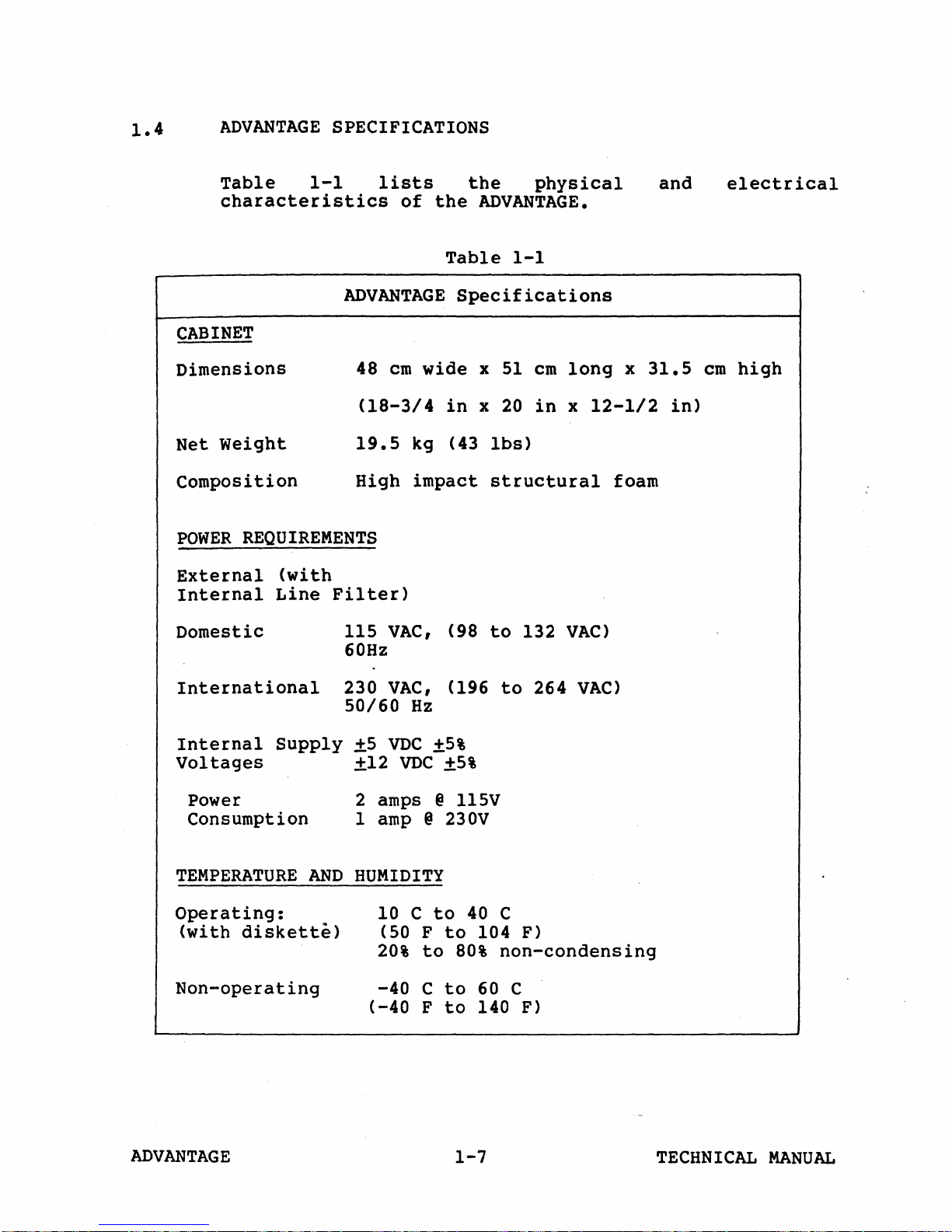
1.4
ADVANTAGE
SPECIFICATIONS
Table
characteristics
CABINET
Dimensions
Net
Weight
Composition
POWER
External
Internal
REQUIREMENTS
(with
Line
Domestic
1-1
lists
ADVANTAGE
48
(18-3/4
19.5
High
Filter)
115
VAC,
60Hz
of
the
Table
cm
wide x 51
in
kg (43
impact
the
physical
ADVANTAGE.
1-1
Specifications
cm
x
20
in
lbs)
structural
(98
to
132
long
x
12-112
VAC)
x
31.5
foam
and
in)
electrical
cm
high
International
Internal
Supply
Voltages
Power
Consumption
TEMPERATURE
Operating:
(with
diskette)
Non-operating
230
50/60
±5
AND
VAC,
Hz
VDC
±5%
+12
VDC
±5%
2 amps @
1
amp
@ 230V
HUMIDITY
10 C
(50 F
20%
to
to
to
-40 C to
(-40 F to
(196
ll5V
40
104 F)
80%
60 C
140 F)
to
264
VAC)
C
non-condensing
ADVANTAGE
1-7
TECHNICAL
MANUAL
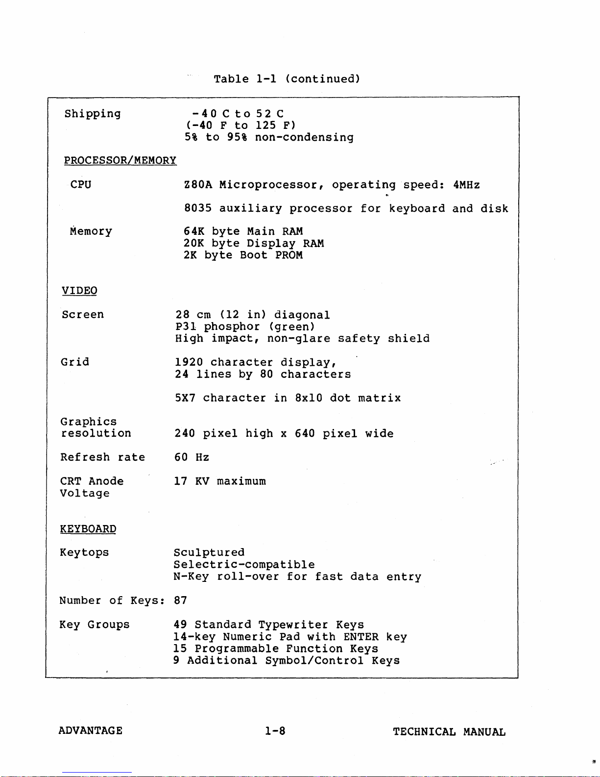
Table
1-1
(continued)
Shipping
PROCESSOR/MEMORY
CPU
Memory
VIDEO
Screen
28
P31
High
Grid
1920
24
5X7
-40Cto52C
(-40
5%
Z80A
8035
64K
20K
2K
F
to
95%
Microprocessor,
auxiliary
byte
byte
byte
cm
(12
phosphor
impact,
character
lines
character
to
125 F)
non-condensing
processor
Main
RAM
Display
Boot
in)
PROM
diagonal
(green)
non-glare
display,
by
80
characters
in
8xlO
RAM
operating
for
safety
dot
matrix
speed:
keyboard
shield
4MHz
and
disk
Graphics
resolution
Refresh
CRT
Anode
rate
Voltage
KEYBOARD
Key
tops
Number
Key
of
Groups
Keys:
240
60
17
pixel
Hz
KV
high
maximum
x 640
Sculptured
Selectric-compatible
N-Key
roll-over
87
49
Standard
l4-key
15
Additional
9
Numeric Pad
Programmable
Typewriter
Function
Symbol/Control
for
pixel
fast
with
data
Keys
ENTER
Keys
wide
entry
key
Keys
ADVANTAGE
1-8
TECHNICAL
MANUAL
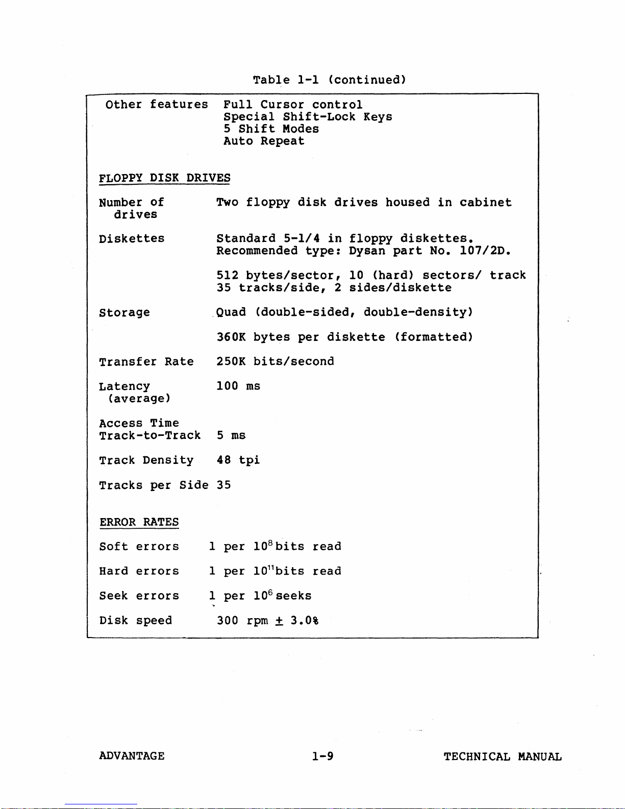
Table
1-1
(continued)
Other
FLOPPY
Number
features
DISK
of
drives
Diskettes
storage
Transfer
Latency
(average)
DRIVES
Rate
Full
Special
5
Auto
Two
Standard
Cursor
Shift
Repeat
floppy
Shift-Lock
Modes
5-1/4
Recommended
512
bytes/sector,
35
tracks/side,
.Quad
360K
250K
100
(double-sided,
bytes
bits/second
ms
control
disk
type:
per
Keys
drives
in
floppy
Dysan
10
(hard)
2
sides/diskette
double-density)
diskette
housed
in
diskettes.
part
No.
sectors/
(formatted)
cabinet
107/2D.
track
Access
Time
Track-to-Track
Track
Tracks
ERROR
Soft
Hard
Seek
Disk
Density
per
RATES
errors
errors
errors
speed
Side
1
1
1
5
48
35
per
per
per
300
ms
tpi
108bits
l011bi
106 seeks
rpm
read
ts
read
+ 3.0%
ADVANTAGE
1-9
TECHNICAL
MANUAL
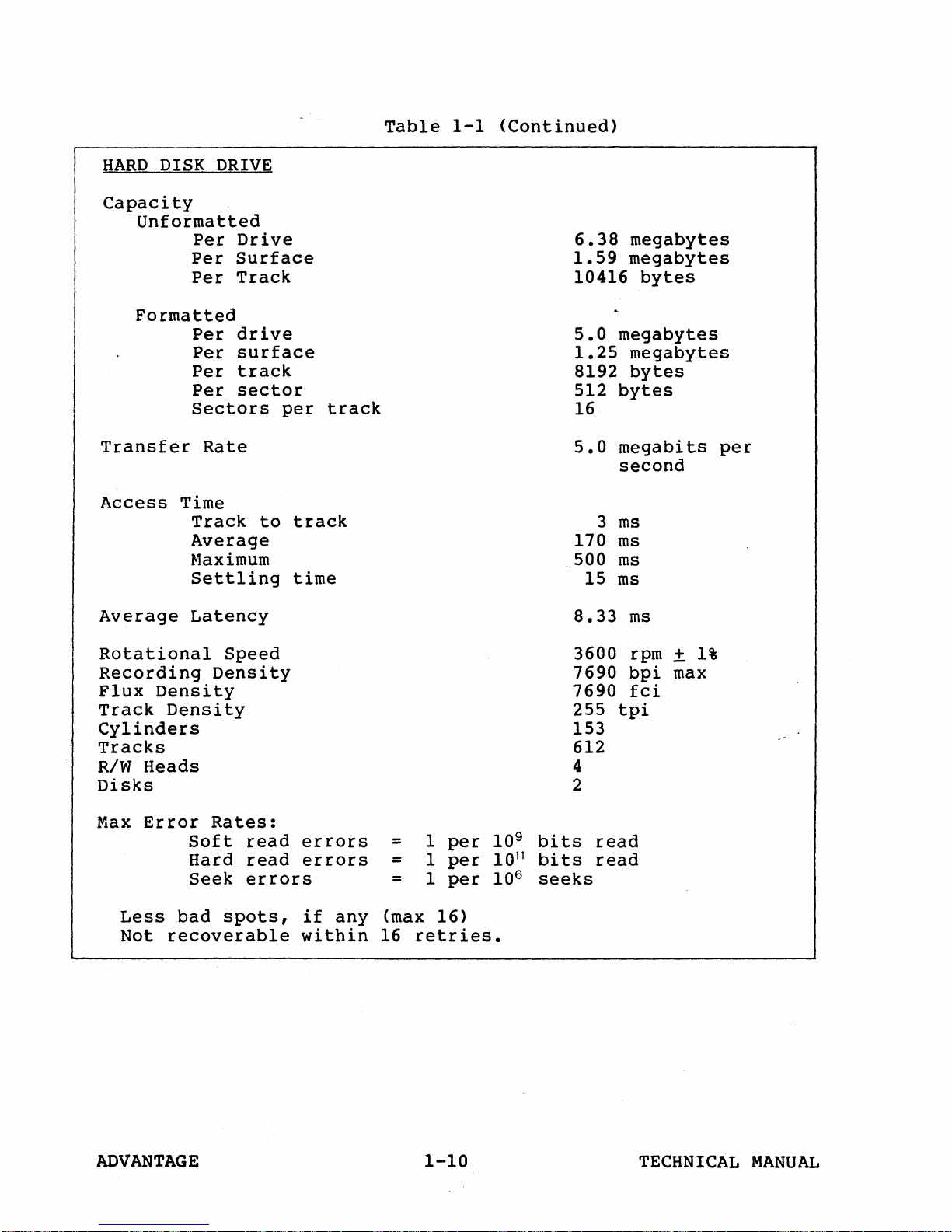
Table
1-1
<Continued)
HARD
DISK
Capacity
Unformatted
Formatted
Transfer
Access
Average
DRIVE
Per
Drive
Per
Surface
Per
Track
Per
drive
Per
surface
Per
track
Per
sector
Sectors
Rate
Time
Track
Average
Maximum
Settling
Latency
to
per
track
time
track
6.38
1.59
10416
5.0
1.25
8192
512
16
5.0
3
170
.500
15
8.33
megabytes
megabytes
bytes
megabytes
megabytes
bytes
bytes
megabits
second
ms
ms
ms
ms
ms
per
Rotational
Recording
Flux
Track
Density
Density
Cylinders
Tracks
R/w
Heads
Disks
Max
Error
Less
Not
bad
recoverable
Speed
Density
Rates:
Soft
Hard
Seek
spots,
read
read
errors
errors
errors
if
any
within
=
=
=
(max
16
1
per
1
per
1
per
16)
retries.
3600
7690
7690
255
153
612
4
2
109 bits
11
10
bi
ts
106 seeks
tpi
read
read
rpm
bpi
fci
±
max
1%
ADVANTAGE
1-10
TECHNICAL
MANUAL
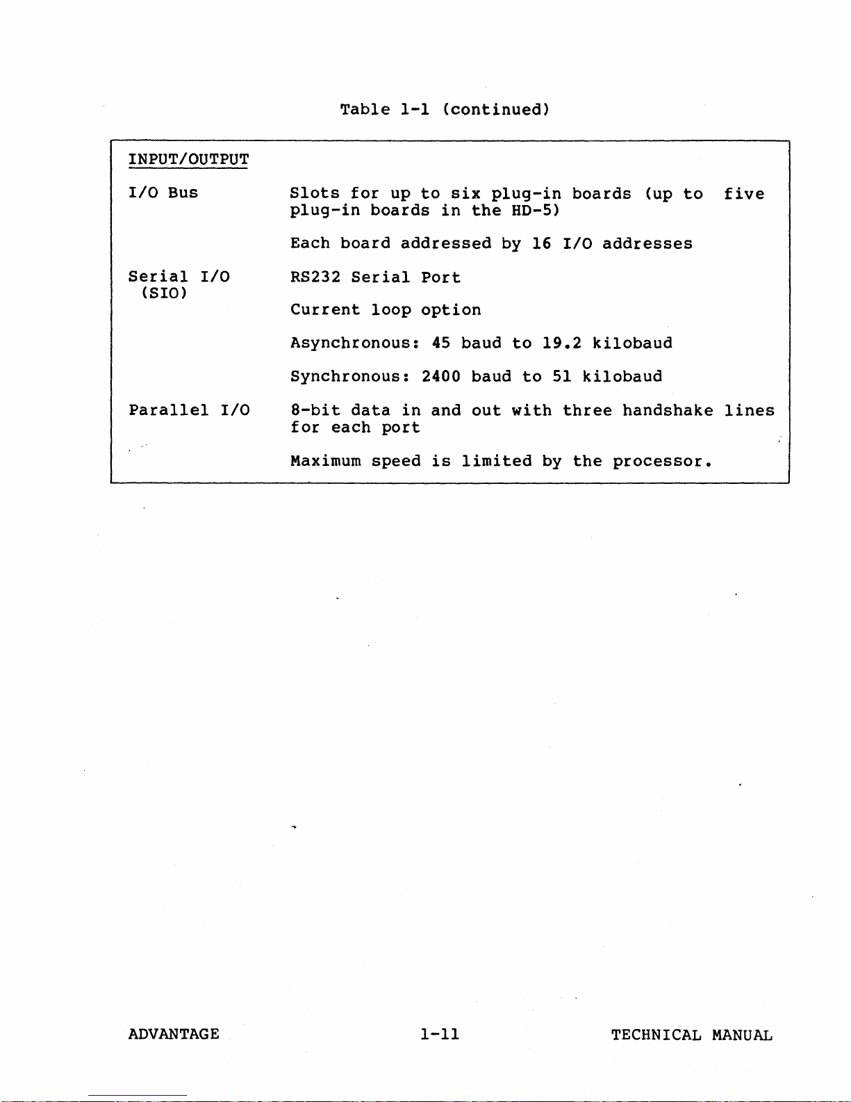
INPUT/OUTPUT
I/O
Bus
Table
Slots
plug-in
for
boards
1-1
up
(continued)
to
six
in
the
plug-in
HD-5)
boards
(up
to
five
Serial
(SIO)
Parallel
I/O
I/O
Each
RS232
Current
board
Serial
loop
addressed
Asynchronous:
Synchronous:
8-bit
for
Maximum
data
each
in
port
speed
Port
option
45
baud
2400
and
is
limited
by 16
baud
out
to
19.2
to
with
by
I/O
51
kilobaud
three
the
addresses
kilobaud
handshake
processor.
lines
ADVANTAGE
1-11
TECHNICAL
MANUAL

ADVANTAGE
OPERATION
2
2.1
2.1.1
This
the
keyboard
also
floppy
performing
OPERATING
The
keyboard
are
system
diskette
chapter
ADVANTAGE.
and
provides
drive(s),
a
CONTROLS
ADVANTAGE
and
a power
Reset
loading
Keyboard
Primary
commands
keyboard
keys,
standard
codes.
tabu1~tions
system
and
is
described
ASCJI
Keys
in
describes
It
rear
panel
instructions
booting
system
operating
rear
panel
switch,
button.
and
control
data
illustrated
in
codes
and
their
Appendix
startup
contains
controls
a
reset.
controls.
screen
For
operation
unloading
is
from
the
in
Table
as
well
codes
A.
and
a
of
for
loading
program,
controls
brightness
procedures
maintained
ADVANTAGE
Figure
2-1.
as
additional
are
listed
general
description
the
ADVANTAGE.
diskettes
and
consist
On
the
control,
of
the
are
by
keyboard.
2-1.
The
There
keys
under
operation
of
in
methods
of
rear
panel
and
disk
drives,
given.
entering
are
generate
8-bit
various
of
the
It
the
for
the
the
The
87
hex
Characters
on
maintained
where
ADVANTAGE
the
CRT
the
entered
screen
cursor
next
from
under
marks
character
The
ADVANTAGE
Figure
2-1
the
program
the
entry
Keyboard
2-1
keyboard
control.
position
will
be
are
on
displayed
A
program-
the
displayed.
TECHNICAL
screen
MANUAL
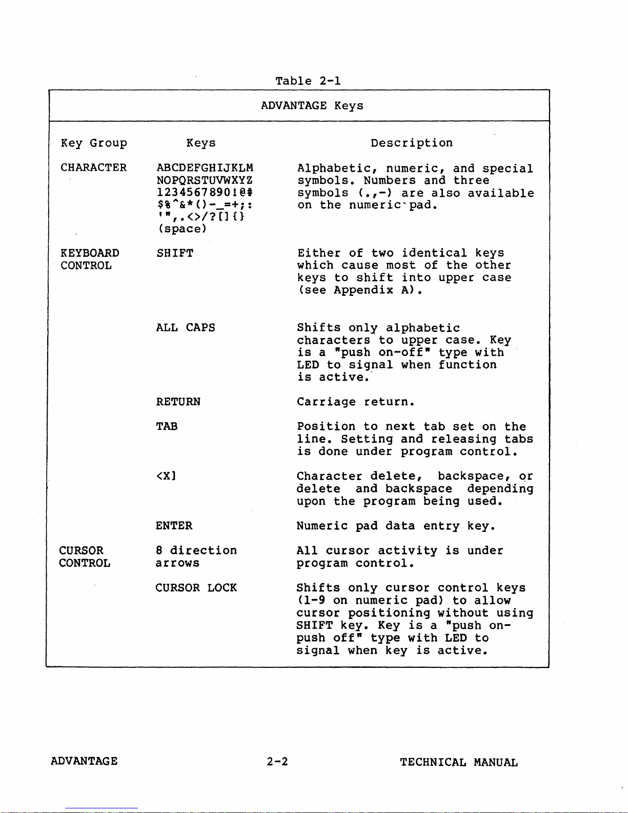
Table
2-1
Key
Group
CHARACTER
KEYBOARD
CONTROL
ADVANTAGE
Keys
ABCDEFGHIJKLM
NOPQRSTUVWXYZ
l234567890!
$%A&*()
'",.<>I?[]{}
__
@#
=+;:
(space)
SHIFT
ALL
CAPS
RETURN
Keys
Alphabetic,
symbols.
symbols
on
the
Either
which
keys
(see
Shifts
(.,-)
numeric~pad.
of
cause
to
shift
Appendix
only
characters
is
a
"push
LED
to
signal
is
active.'
Carriage
Description
numeric,
Numbers
are
two
identical
most
into
A).
alphabetic
to
upper
on-off"
when
return.
and
and
three
also
of
the
upper
case.
type
function
special
available
keys
other
case
Key
with
CURSOR
CONTROL
TAB
<X]
ENTER
8
direction
arrows
CURSOR
LOCK
Position
line.
is
Setting
done
Character
delete
upon
the
Numeric
All
cursor
program
Shifts
(1-9
cursor
SHIFT
push
signal
only
on
positioning
key.
off"
when
to
next
under
delete,
and
backspace
program
pad
data
activity
control.
cursor
numeric
Key
type
key
tab
and
releasing
program
backspace,
being
entry
is
control
pad)
without
is
a
"push
with
is
LED
active.
set
on
control.
depending
used.
key.
under
to
allow
on-
to
the
tabs
qr
keys
using
ADVANTAGE
2-2
TECHNICAL
MANUAL
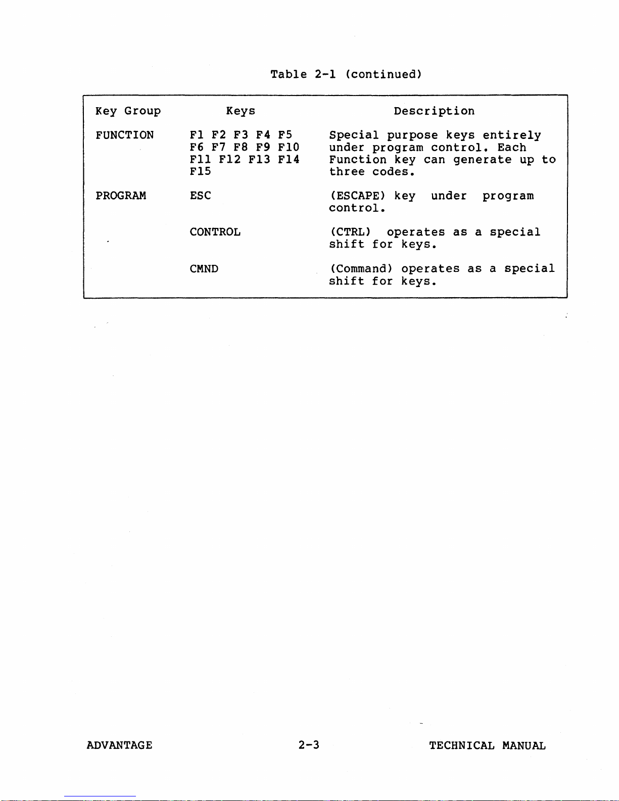
Table
2-1
(continued)
Key Group
FUNCTION
PROGRAM
Keys
Fl
F2
F3 F4
F6 F7
Fll
Fa
Fl2
FlS
ESC
CONTROL
CMND
FS
F9
FlO
F13 F14
Special
under
program
Function
three
codes.
(ESCAPE)
control.
(CTRL)
shift
for
(Command)
shift
for
Description
purpose
control.
key
can
key
under
operates
keys.
operates
keys.
keys
entirely
generate
program
as
a
as
Each
up
special
a
special
to
ADVANTAGE
2-3
TECHNICAL
MANUAL
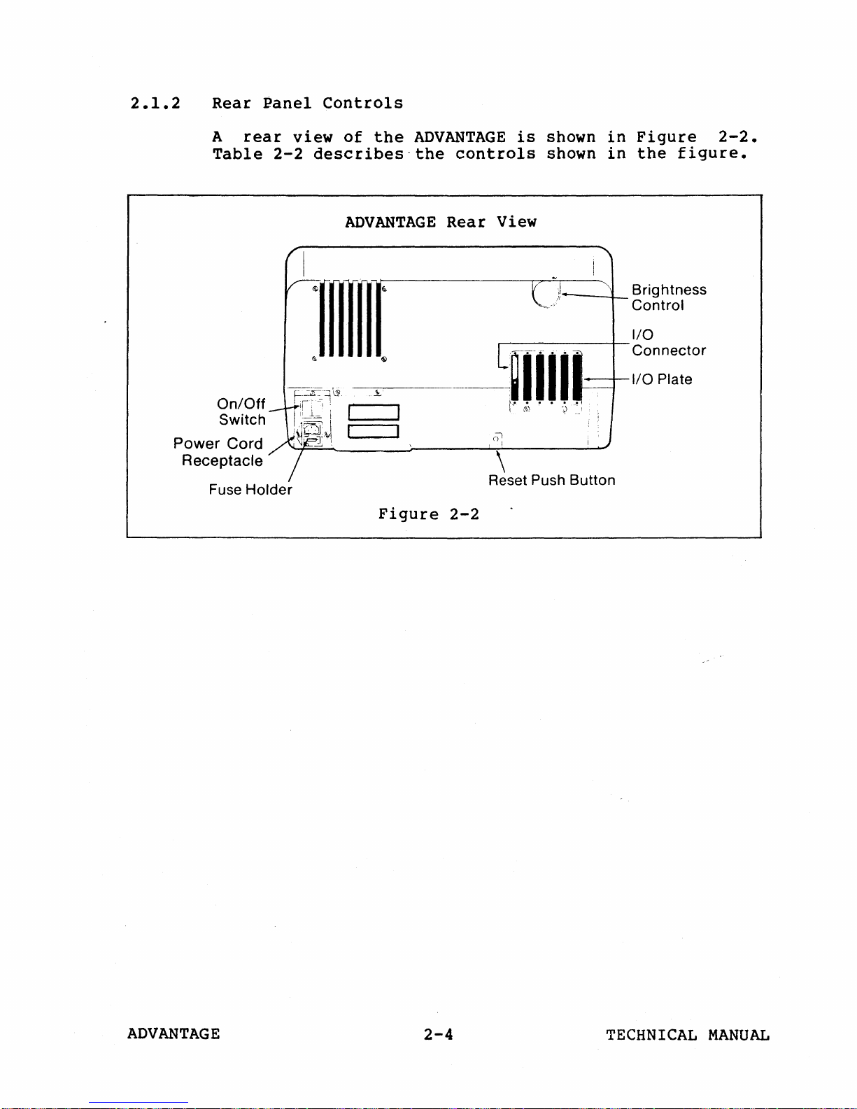
2.1.2
Rear
A
rear
Table
Panel
view
2-2
Controls
of
the
ADVANTAGE
describes-the
controls
is
shown
shown
in
in
Figure
the
figure.
2-2.
On/Off
Switch
Power Cord
Receptacle
Fuse
Holder
ADVANTAGE
Rear
Figure
View
<l)
\
Reset Push Button
2-2
~-4--
Brightness
Control
ADVANTAGE
2-4
TECHNICAL
MANUAL
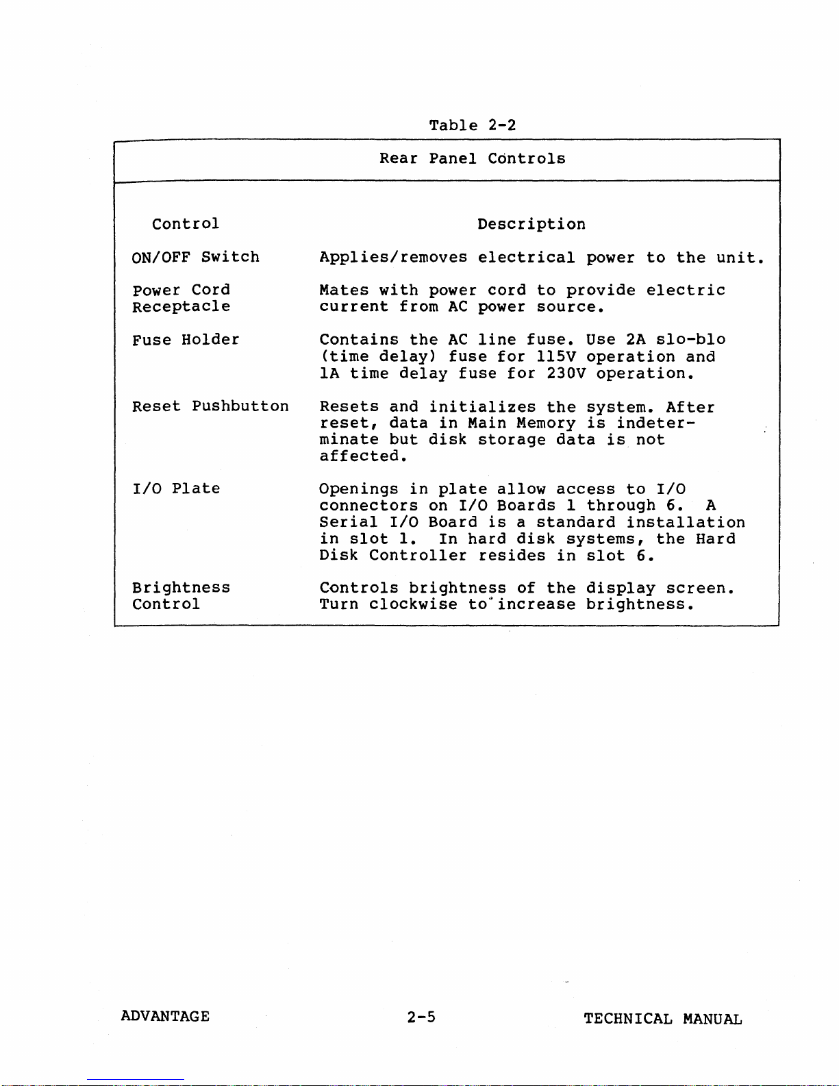
Table
2-2
Control
ON/OFF
Switch
Power Cord
Receptacle
Fuse
Reset
I/O
Holder
Pushbutton
Plate
Rear
Panel
Applies/removes
Mates
current
Contains
(time
IA
Resets
reset,
minate
time
with
from
the
delay)
delay
and
data
but
power
AC
AC
initializes
in
disk
affected.
Openings
connectors
Serial
in
slot
Disk
in
plate
on
I/O
Board
1.
In
Controller
Controls
Description
electrical
cord
power
line
fuse
fuse
fuse.
for
for
Main Memory
storage
allow
I/O
Boards
is
a
hard
disk
resides
power
to
provide
source.
Use
llSV
230V
the
operation
operation.
system.
is
data
access
I
through
standard
systems,
in
slot
to
electric
2A
slo-blo
After
indeter-
is
not
to
I/O
6.
installation
the
6.
the
and
Hard
unit.
A
Brightness
Control
Controls
Turn
clockwise
brightness
to~increase
of
the
display
brightness.
screen.
ADVANTAGE
2-5
TECHNICAL
MANUAL
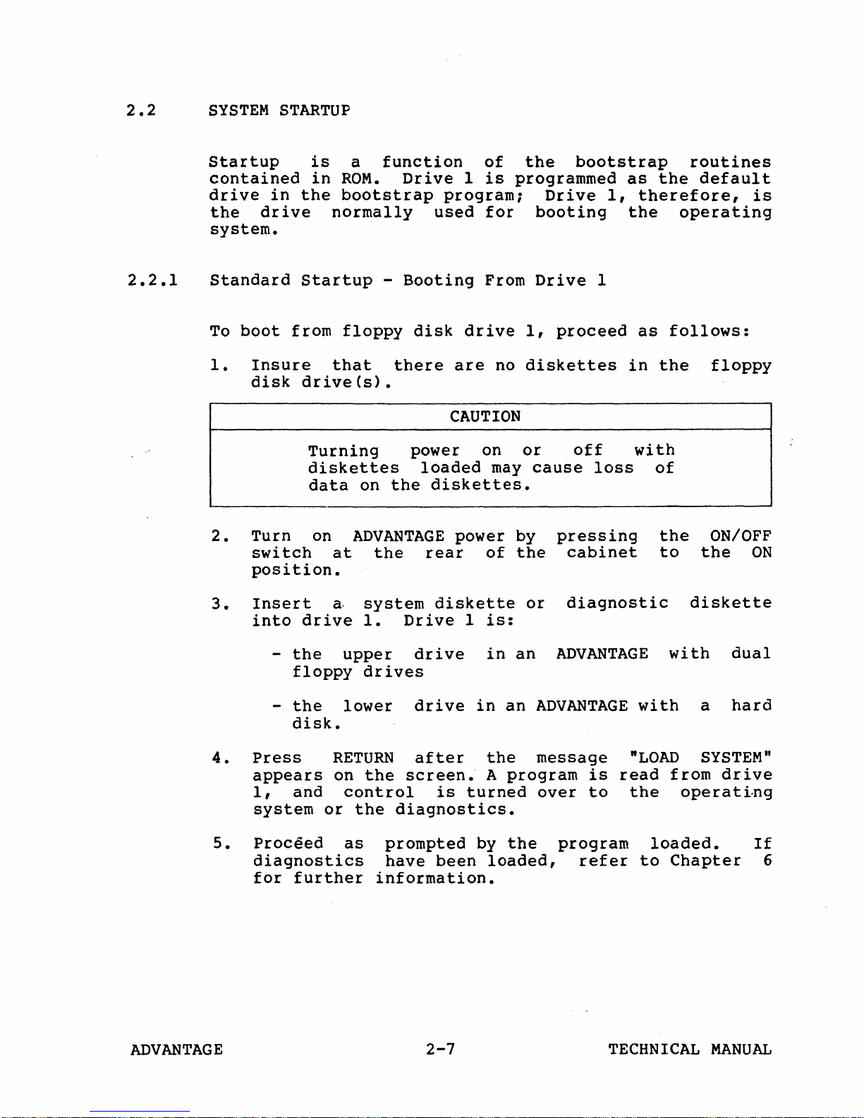
2.2
SYSTEM
STARTUP
2.2.1
Startup
contained
drive
the
in
drive
system.
Standard
To
boot
1.
Insure
disk
2.
Turn
switch
position.
is
in
ROM.
the
bootstrap
normally
Startup
from
floppy
that
drive(s).
Turning
diskettes
data
on
at
a
function
Drive
program;
used
-
Booting
disk
there
CAUTION
power on
loaded
on
the
diskettes.
ADVANTAGE
the
rear
of
the
1
is
programmed
for
From
drive
are
1,
no
diskettes
or
may
power by
of
the
bootstrap
Drive
booting
Drive
proceed
off
cause
pressing
cabinet
1,
1
loss
as
the
therefore,
the
in
as
the
operating
follows:
with
of
the
to
routines
default
floppy
ON/OFF
the
is
ON
3.
Insert
into
4.
Press
appears
1,
system
5.
Proceed
diagnostics
for
drive
-
the
floppy
-
the
disk.
and
further
a
system
1.
upper
drives
lower
RETURN
on
the
control
or
the
as
information.
diskette
Drive
1
drive
drive
after
screen.
is
turned
diagnostics.
prompted
have
been
is:
in
an
in
an
the
A
program
by
the
loaded,
or
diagnostic
ADVANTAGE
ADVANTAGE
message
is
over
to
program
refer
with
"LOAD
read
the
loaded.
to
diskette
with
a
SYSTEM"
from
drive
operating
Chapter
dual
hard
If
6
ADVANTAGE
2-7
TECHNICAL
MANUAL
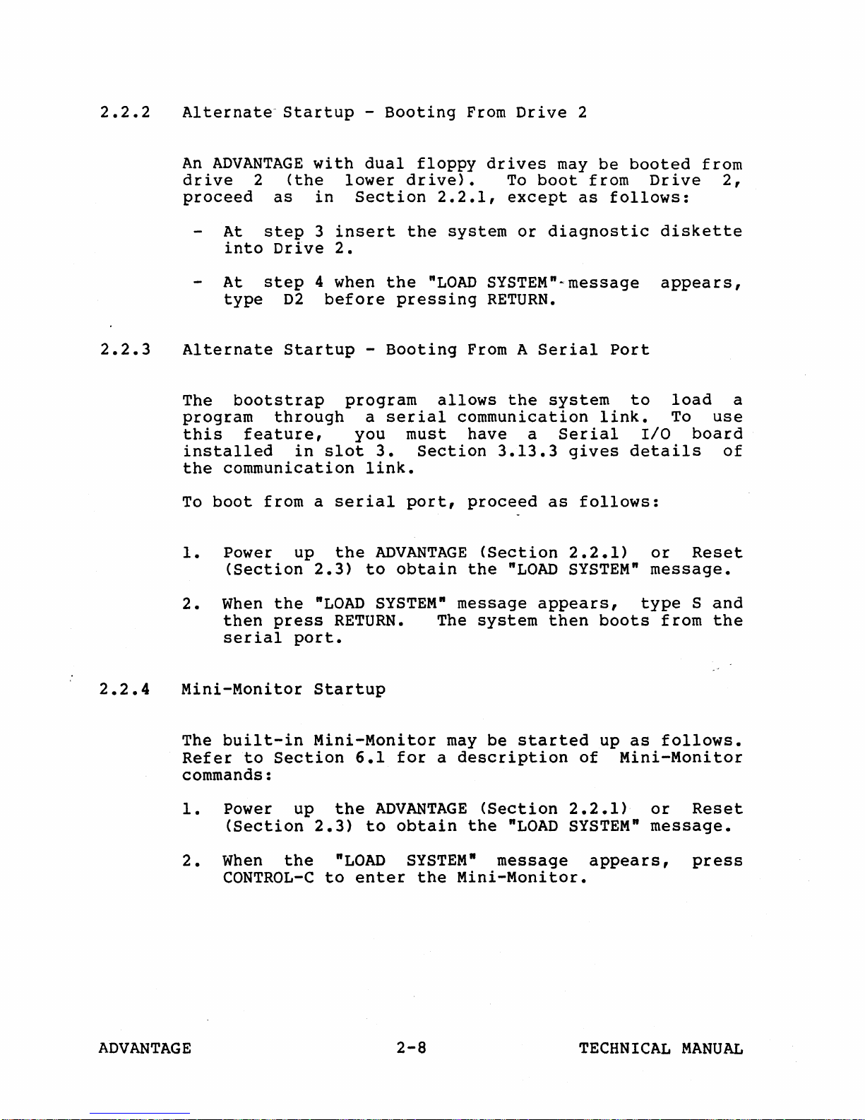
2.2.2
Alternate-
An
ADVANTAGE
drive
2
proceed
At
into
At
type
Startup
(the
as
step
Drive
step
D2
with
lower
in
Section
3
insert
2.
4 when
before
-
Booting
dual
the
pressing
floppy
drive).
2.2.1,
the
system
"LOAD
From
Drive
drives
To
except
or
SYSTEM"~message
2
may
be
boot
from
as
diagnostic
follows:
RETURN.
booted
Drive
diskette
appears,
from
2,
2.2.3
2.2.4
Alternate
The
bootstrap
program
this
Startup
through
feature,
installed
the
communication
To
boot
1.
from a serial
Power up
(Section
2.
When
then
the
press
serial
Mini-Monitor
The
built-in
Refer
to
Section
commands:
-
program
a
you
in
slot
3.
link.
the
ADVANTAGE
2.3)
"LOAD
to
SYSTEM"
RETURN.
port.
Startup
Mini-Monitor
6.1
Booting
allows
serial
must
Section
port,
obtain
The
for
a
From A
the
Serial
system
communication
have
a
3.13.3
proceed
as
(Section
the
"LOAD
message
system
may
be
appears,
then
started
description
Port
link.
Serial
gives
follows:
2.2.1)
SYSTEM"
boots
up
of
to
load
To
1/0
details
or
use
board
of
Reset
message.
type
as
Sand
from
the
follows.
Mini-Monitor
a
1.
Power up
(Section
2.
When
the
CONTROL-C
ADVANTAGE
the
2.3)
"LOAD
to
ADVANTAGE
to
obtain
SYSTEM"
enter
the
2-8
(Section
the
"LOAD
2.2.1)
SYSTEM"
message
Mini-Monitor.
or
message.
appears,
TECHNICAL
Reset
press
MANUAL
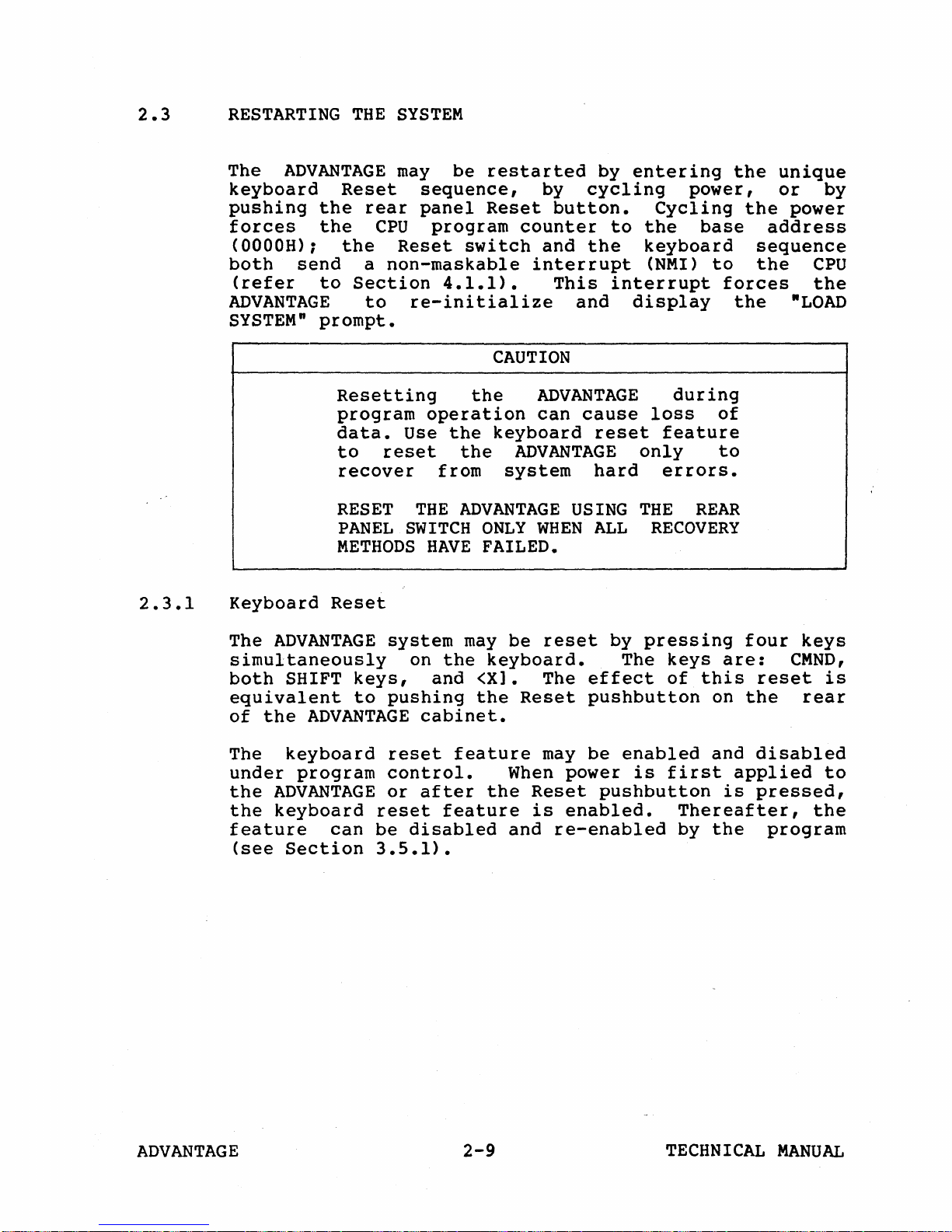
2.3
RESTARTING
THE
SYSTEM
2.3.1
The
ADVANTAGE
keyboard
pushing
forces
the
the
(OOOOH);
both
(refer
send
to
ADVANTAGE
SYSTEM"
prompt.
Resetting
program
data.
to
RESET
PANEL
METHODS
Keyboard
Reset
may
Reset
rear
CPU
the
Reset
a
non-maskable
Section
to
reset
recover
be
restarted
sequence,
panel
Reset
program
switch
4.1.1).
re-initialize
CAUTION
the
operation
Use
the
keyboard
the
from
THE
ADVANTAGE
SWITCH
HAVE
ONLY
FAILED.
by
by
cycling
button.
counter
and
the
interrupt
This
and
ADVANTAGE
can
cause
reset
ADVANTAGE
system
hard
USING
WHEN
ALL
entering
Cycling
to
the
keyboard
(NMI)
interrupt
display
during
loss
feature
only
errors.
THE
RECOVERY
the
power,
base
to
forces
the
of
to
REAR
unique
or
the
power
address
sequence
the
"LOAD
by
CPU
the
The
ADVANTAGE
simultaneously
both
equivalent
of
The
under
the
the
feature
(see
SHIFT
keys,
to
the
ADVANTAGE
keyboard
program
ADVANTAGE
keyboard
can
Section
system
on
pushing
cabinet.
reset
control.
or
after
reset
be
disabled
3.5.1).
may
the
and
<Xl. The
the
feature
feature
be
reset
keyboard.
Reset
may
When
the
and
power
Reset
is
enabled.
re-enab1ed
by
pressing
The
keys
effect
of
pushbutton
be
enabled
is
first
pushbutton
Thereafter,
by
are:
this
on
and
is
the
four
CMND,
reset
the
disabled
applied
pressed,
program
keys
is
rear
to
the
ADVANTAGE
2-9
TECHNICAL
MANUAL
IMPLEMENTING
ADVANTAGE
FEATURES
3
3.1
3.2
3.2.1
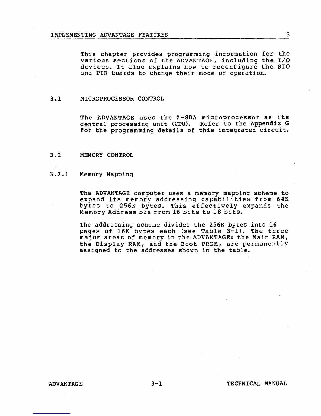
This
various
devices.
and
chapter
PIO
boards
provides
sections
It
also
MICROPROCESSOR
The
central
for
MEMORY
ADVANTAGE
processing
the
programming
CONTROL
Memory Mapping
The
expand
bytes
Memory
ADV~TAGE
its
to
memory
256K
Address
of
explains
to
change
CONTROL
uses
unit
details
computer
addressing
bytes.
bus
from
programming
the
ADVANTAGE,
how
their
the
Z-80A
(CPU).
of
uses
This
16
bits
a memory
effectively
information
including
to
reconfigure
mode
of
operation.
microprocessor
Refer
this
to
the
integrated
mapping
capabilities
to
18
bits.
for
the
the
as
Appendix
circuit.
scheme
from
expands
the
I/O
SIO
its
G
to
64K
the
The
addressing
pages
major
the
Display
assigned
of
areas
to
16K
the
scheme
bytes
of
memory
RAM,
divides
each
in
and
the
addresses
the
(see
the
Boot
shown
Table
ADVANTAGE:
PROM,
in
256K
the
bytes
3-1).
the
are
table.
into
The
Main
16
three
RAM,
permanently
ADVANTAGE
3-1
TECHNICAL
MANUAL
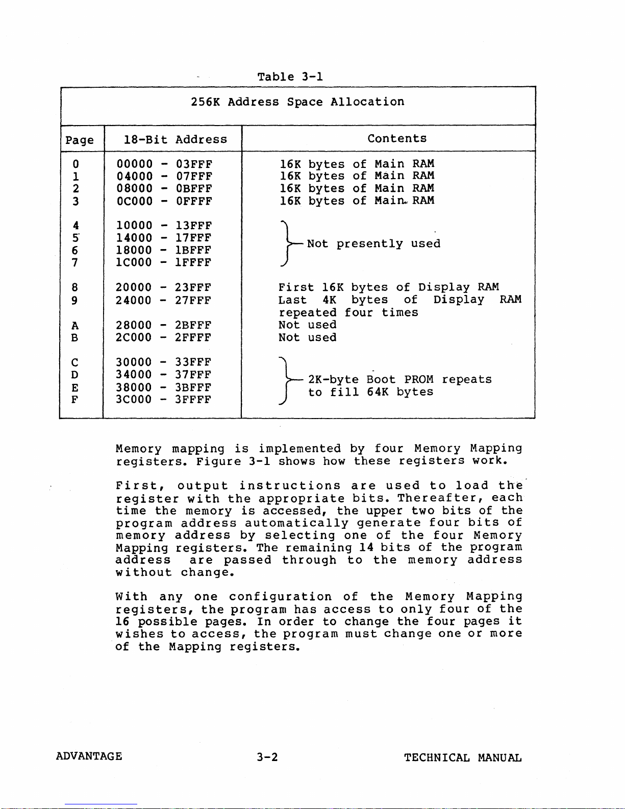
Table
3-1
Page
0
1
2
3
4
5"
6
7
8
9
A
B
C
D
E
F
2S6K
18-Bit
00000
04000 -
08000 -
OCOOO
10000
14000
18000 1COOO
20000
24000 -
Address
- 03FFF
07FFF
OBFFF
OFFFF
-
- 13FFF
- 17FFF
1BFFF
- 1FFFF
- 23FFF
27FFF
28000 - 2BFFF
2COOO
30000 -
34000
38000 -
3COOO
- 2FFFF
33FFF
37FFF
-
3BFFF
- 3FFFF
Address
Space
bytes
16K
bytes
16K
bytes
16K
bytes
16K
}
Not
First
Last
16K
4K
repeated
Not
used
Not
used
}
2K-byte
to
Allocation
Contents
Main
of
Main
of
Main
of
Main..
of
presently
bytes
bytes
four
times
-
Boot
fill
64K
RAM
RAM
RAM
RAM
used
of
Display
of
PROl~
bytes
Display
repeats
RAM
RAM
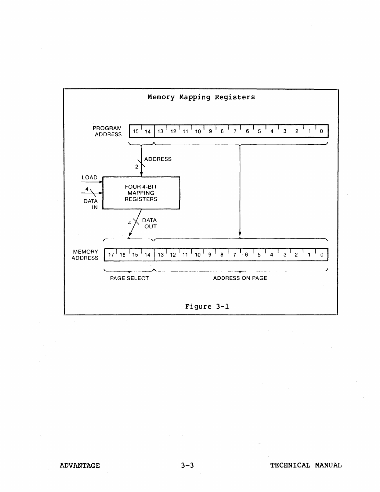
Memory
mapping
registers.
First,
output
register
time
program
memory
Mapping
the
address
address
registers.
memory
address
wi
thou t change.
With
anyone
registers,
16
possible
wishes
of
the
to
Mapping
Figure
with
are
the
pages.
access,
is
implemented
3-1
shows
instructions
the
appropriate
is
accessed,
automatically
by
selecting
The
remaining
passed
through
configuration
program
In
the
has
order
program
registers.
by
how
these
are
bits.
the
one
to
of
access
to
change
must
four
registers
used
Thereafter,
upper
generate
of
the
14
bits
the
the
to
only
the
change
Memory Mapping
work.
to
load
the
each
two
memory
Memory
four
of
four
bits
four
the
four
one
of
bits
Memory
program
address
Mapping
of
the
pages
or
more
the
of
it
ADVANTAGE
3-2
TECHNICAL
MANUAL
Memory Mapping
Registers
PROGRAM
LOAD
4\.
\.
DATA
IN
MEMORY
ADDRESS
ADDRESS
(
117
1 16 I 15 I 14 1
\
PAGE
115
114113
\
W 9
ADDRESS
'\
r"-
2
FOUR
4-BIT
MAPPING
REGISTERS
jDATA
OUT
A "
1 12 1
11
I 10 I
1\
I 12 1
11
13
I 10 I
-
w
SELECT
"
Figure
1
918
I
9 1 8
ADDRESS
3-1
7 I
7
,
II
1·6
w
ON
6
I I
5
1 5 1
PAGE
I
I
3
4 2
1 312 1
4
1
1 0
1
1
1
,
I
1
o I
I
ADVANTAGE
3-3
TECHNICAL
MANUAL
•
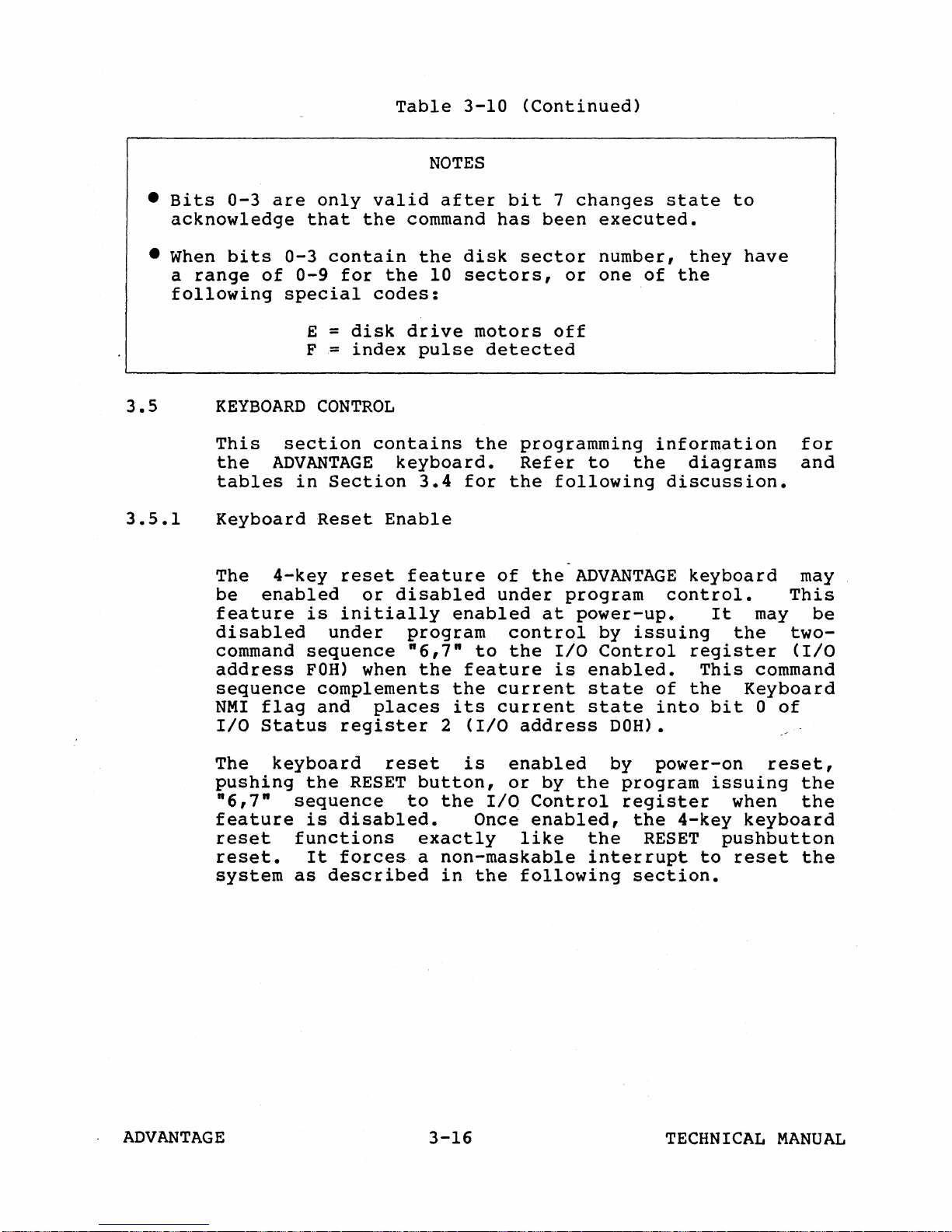
Bits
0-3
acknowledge
•
When
a
bits
range
following
are
0-3
of
special
only
that
0-9
E =
F =
valid
the
contain
for
the
codes:
disk
index
Table
NOTES
after
command
the
10
drive
pulse
3-10
(Continued)
bit
has
disk
sector
sectors,
motors
detected
7
changes
been
or
off
state
executed
number,
one
of
•
they
the
to
have
3.5
3.5.1
KEYBOARD
This
the
tables
section
ADVANTAGE
in
Keyboard
The
be
feature
4-key
enabled
is
disabled
command
address
sequence
FOH)
sequence
NMI
flag
I/O
Status
The
pushing
"6,7"
feature
reset
reset.
system
keyboard
the
sequence
is
functions
It
as
CONTROL
contains
keyboard.
Section
Reset
reset
or
3.4
Enable
feature
disabled
initially
under
program
"6,7"
when
the
complements
and
places
register
reset
RESET
button,
to
disabled.
exactly
forces
a
described
the
programming
Refer
for
the
following
of
the
under
enabled
at
control
to
the
I/O
feature
the
its
2
(I/O
is
the
Once
current
current
or
I/O
is
address
enabled
by
Control
enabled,
like
non-maskable
in
the
following
information
to
the
-
ADVANTAGE
program
power-up.
by
issuing
Control
enabled.
state
state
of
into
DOH).
by
power-on
the
program
register
the
the
RESET
interrupt
section.
diagrams
discussion.
keyboard
control.
It
may
the
register
This
the
command
Keyboard
bit
0
issuing
when
4-key
keyboard
pushbutton
to
reset
for
and
may
This
be
two-
(I/O
of
reset,
the
the
the
ADVANTAGE
3-16
TECHNICAL
MANUAL
 Loading...