


6500 DPG
Proven Performance
OWNER’S MANUAL
MO DEL 6500 DPG, I TEM # 165961
Diesel Port a bl e G enerator
M165961B
Call Customer Service at 1-800-270-0810
Hours: Monday - Friday 7:00 AM to 5:00 PM CST
Saturday 7:30 AM to 11:30 AM CST
THANK YOU
Thank you for purchasing a NorthStar Diesel Series Generator. Your machi ne is desi gned for
long life, dependability, and the top performance you demand. Please take time now to read
through this manual so you can better understand the machine’s operation, maintenance and
safety precautions. Everyone who operates this generator must read and understand this m anual.
T he time you t ake now will p rolong you r gene rato r’s l ife a nd prep are yo u fo r i ts saf e ope ration .
Enj oy the exceptional perform ance of your NorthStar Diesel Series Generator.
IMPORTANT
Make certain the operator:
- Reads and understands the manuals pertai ning to this machine.
- Is instructed in safe and proper operation of this m achine.
NOTICE
K-BAR Industries Incorporated reserves the right to make improvements in design and/or
changes in specifications at any time without incurring any obligation to install them on units
previousl y sold.
TABL E OF CONT ENTS
Thank you 1
Specifications 2
Machine component identification 3
Gener ator f eature s 4-5
Introduction 5
A NSI safety definitions 5
Rules for safe operation 5-6
Installation 6
Load applic ation 6-8
Pre- star t up prepar ation 8
Electric E ngine St ar ting 8-9
Manual Engine Star ting 8-9
Engine Shutdown 9
Engine care 9
Gener ator car e 9
Engine Fuel Line Bleeding 9
Tr oubleshooting 10-11
1
SPECIFICATIONS
Item Nu mb er 165961
Maxi mum O utpu t 6500 Watts (W )
Continuous Output 5500 Watts (W )
Voltage 120 / 240 Volt (V)
Phase Single pha s e ( 4- wire)
Frequency 56.5 - 63.3 Hert z (Hz)
Power Fact or 1.0 p.f.
Engine 10 HP HATZ 1B 40
Engine Speed 3390 - 3798 RPM
Fuel Type Diesel
Fuel Capacity 6.5 gallons (24. 6 L)
Oil Capacity 1.76 US quar ts (1. 65 L)
St ar ting Method Electric / Recoil
120V Recept ac le 20 Amp (A) Duplex G FCI (NEMA 5-20R)
30 Amp (A) Loc k ing ( NEMA L5- 30R)
120/240V Recept ac le 30 Amp (A) Loc k ing ( NE MA L14- 30R)
Circuit Breakers 30 Amp (A) M agnetic, Qty. 1
20 Amp (A), Thermal type, Qty. 2
Gr ounding Sc r ew Receives 10 Ga. Fork Terminal
Battery 12-Volt battery with an amper e- hour r ating
of at least 36 AH
Dimensions
Length 34.00” ( 86.4 cm)
Width 23.25” ( 59.1 cm)
Height 22.25” ( 56.5 cm)
Dry W eight 118 lb. ( 54 k g)
Gr os s Weight 310 lb. ( 141 kg)
2
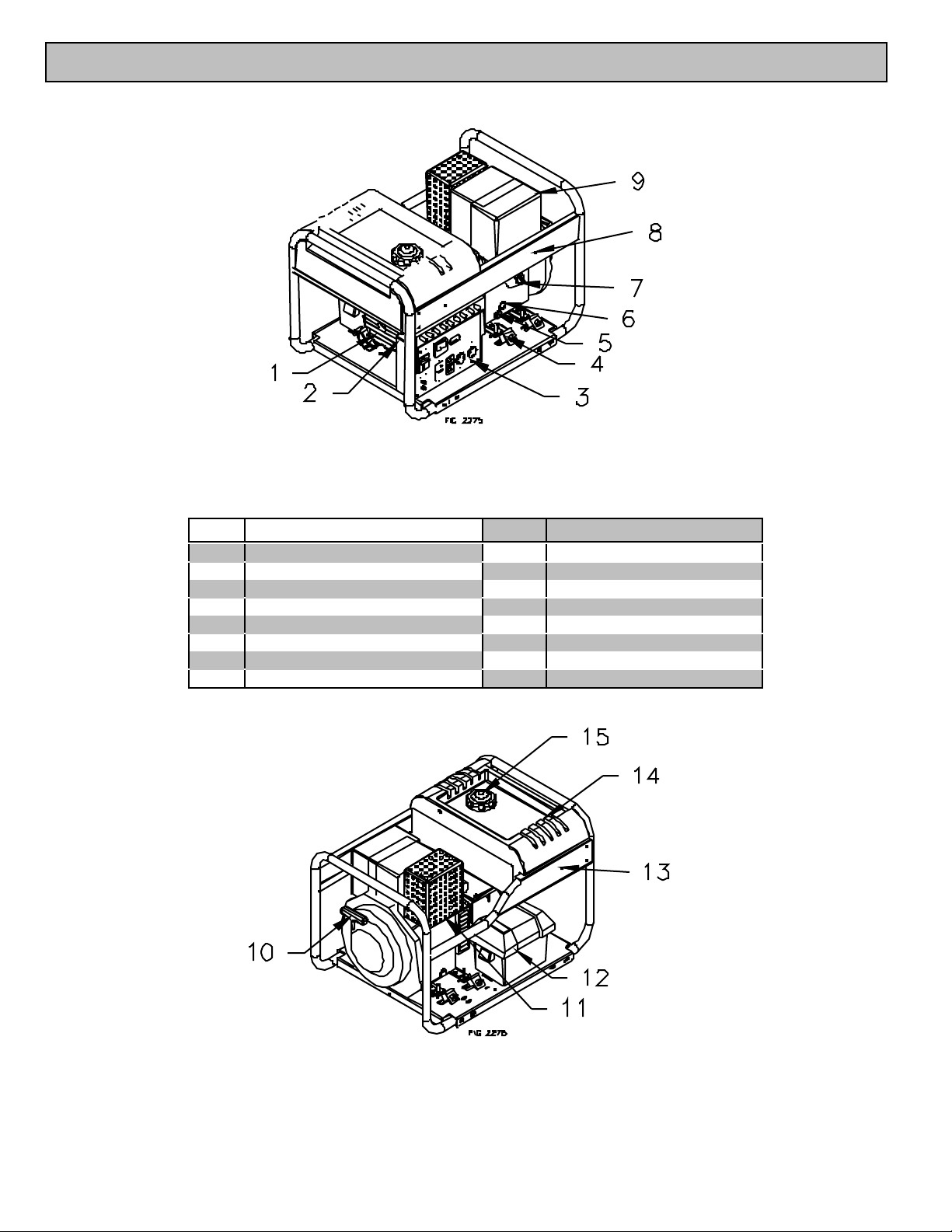
MACHI NE COMPO NENT IDENTIF ICATIO N
Figure 1 (Ref. 1-9)
2275
Ref. Description Ref. Description
1 Generator 9 Air Cl eaner Housing
2 Grounding Screw 10 Rec oil Hand le
3 Control Panel 11 Muffler
4 Isolation Mounts 12 Battery Box
5 Oil Drain Plug 13 Warning Decals
6 Oil Filt er A c cess Cover 14 6.5 Ga l lon Fue l Tank
7 Oil Fill and Dip Stick 15 Fuel Cap with Gauge
8 Oper ati on Instr uc ti ons
Figure 2 (Ref. 10-15) 2276
3
GENERATOR FE ATURES
POWER ED BY
Reference 1 – Generator. The generator is
equipped with a high quality brushless generator. T he
genera tor is maint enanc e free and will pro vi de yea rs of
dependable service. The neutral i s bonded to ground.
Reference 2 - Grounding Screw. Ground the
generator via the grounding screw, to a copper pipe or
r od th at is driven i nto m ois t s oi l.
Refe rence 3 - Control Pa nel. See Figure 3 for
details.
Reference 14 - 6.5 Gallon Fuel Tank. Large
tank allows for extended run capabilities. Always
allow room for fuel expansion by not filling the tank
compl etely fu l l.
Refe rence 15 - Fue l Ca p w ith Gauge . The fuel
cap is extra lar ge, c r eating a lar ge hole fo r refill ing and
a comfortable grip. You can always moni tor the fuel
l e vel wi th out rem o vin g t h e ca p b y u si n g t he fu el le vel
indicator buil t in to the fuel cap.
WARNING Contact a licensed electrician to
wire electri cal pl ugs and/or cord-sets. Improper wiring
could result in a fire or electri cal shock.
Refe rence 4 - Vibr ation I solation M ounts. The
engine and generator are mounted on rubber mounts
that absorb most of the engine vibration. T his feature
eliminates the tendency of the m achi ne to “walk” whi ch
is common with engine powered equipment. If the
mounts appear damaged, replace with factory
approved parts.
Reference 5 - Oil Drain Plug. Removal of plug
allows drainage of oil from the engine. Consult your
Hatz engine manual for further detai ls.
Reference 6 - Oil Filter Access Cover. Your
Hatz engine is equipped with a reusable oil filter. T he
fil ter should be every 1000 hours of use. Consult your
Hatz engine manual for further detai ls.
Reference 7 - Oil Fill and Dip Stick. Consult
your Hatz engine owner’s manual for details
concerning oil change intervals.
Reference 8 - Warning Decal. Nev er operate the
generator or engine until all warning labels are fully
understood. If warning label s are missi ng contact our
customer service department at 1-800-270-0810.
Refe r ence 9 - Air Cleaner Housing. Refer to the
Hatz engi ne manual for air cleaner care.
Reference 10 - Recoil Handle. Consult your
owner’s m anual for engine starting or refer to page 8
of this manual.
Reference 11 - Muffler. Never operate the
generator without the deflector i nstalled in the upright
position.
Re ference 12 - - Batter y Box. Warning: Always
wear safety glasses w hen w orking on or near the
battery. The battery box provides protection for the
battery and will accept a standard lawn tractor size
battery (Group U1-7). The engine requires a 12 volt
battery, with a minimum rating of 36 Ah (Amp-hour).
When installing the battery, always connect the red
colored (“positive” or “+”) cable first. When
disconnecting the battery, always remove the black
colored (“nega tive” or “-”) cable first.
WARNING Sulfuric acid is a corrosive
poison. Avoid contact with skin, eyes or clothing.
Always wear safety gl a sses.
Reference 13 - Decal. Decal describes product
features.
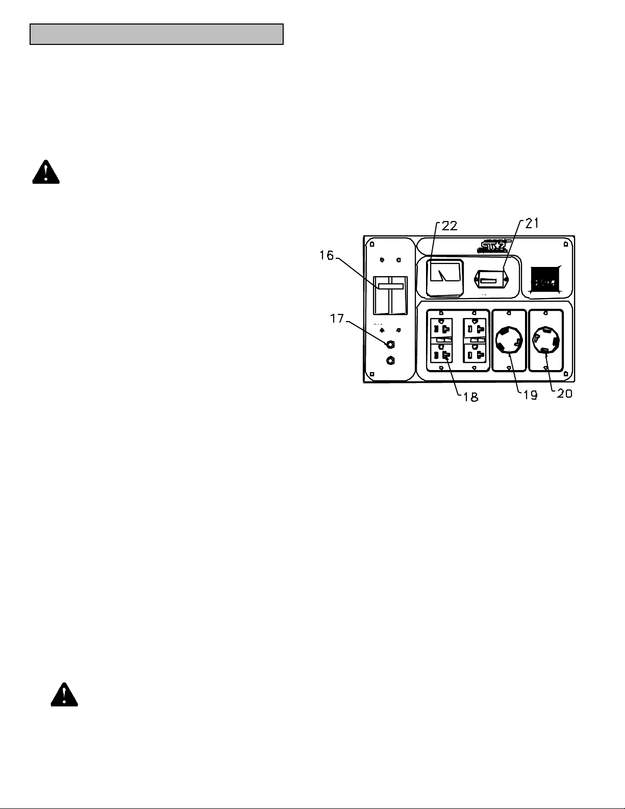
Figure 3 (Ref . 18-26)
Ref er ence 16 - Main Line Br eaker. The main line
breaker is a two-pole thermo-magnetic circui t breaker.
The circuit breaker will protect the generator from
overload and short circuit conditions. To reset the
circuit breaker move the toggle to the OFF position,
then back to the ON position. When this circuit
bre aker i s in the OFF p ositi on , a ll re cepta cl e s will be
off.
Reference 17 - Thermal Circuit Breakers. The
control panel has two thermal circuit breakers. If the
ci rcui t b rea ke r trip s, a bl ac k p ost will e xtend f rom the
circui t breake r, push the bl ack post to reset the ci rcuit
breaker. If the ci rcuit brea ker will not re set, wait two
minutes and try again.
Reference 18 – 120 Volt-20 Amp GFCI Duplex
Receptacle. T he control panel i s equipped with four
1 2 0 Vol t -20 Amp g rou nd f aul t ci rc ui t i nt e rru pt (GF CI )
receptacles (NEMA 5-20R). The receptacles will
accept either NEMA 5-15P or NEMA 5-20P plugs. In
the center of each duplex receptacle there is both a
test/reset button and indicator lamp. If there is a faul t
condition with a load connected to a duplex receptacle,
the indicator lamp will glow and the reset button will
extend. To test the GFCI press the test button and the
reset button should extend. The reset button m ust be
pus hed t o reset the rec e ptacle .
4
 Loading...