


Models NST30ED NST45ED1
NST70ED1
How to install, operate and maintain your Demand Controlled Water Softener
If you have any questions or concerns when installing, operating or maintaining your water softener, call our toll free number:
1-800-972-0135
or visit www.northstarwater.com
When you call, please be prepared to provide the model and serial number of your product, found on the rating decal, located on the back of the controller top cover.
Systems tested and certified by NSF International against NSF/ANSI Standard 44
for hardness reduction and efficiency, and certified to NSF/ANSI Standard 372.
Systems tested and certified by the Water Quality
Association against CSA B483.1.
|
Manufactured and warranted by |
Designed, Engineered & |
North Star Water Treatment Systems |
Assembled in the U.S.A. |
1890 Woodlane Drive |
|
Woodbury, MN 55125 |
Installation and Operation Manual
7366546 (Rev. E 9/1/18)
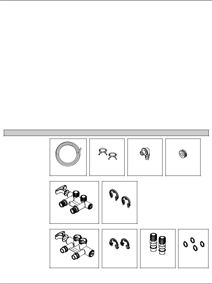
TABLE OF CONTENTS
Page
Specifications & Performance Claims . . . . . . . . . . . . . . . . . . . . . . . . . . . . . . . . . . . . . . . . . . . . . . . . . . . . . . . . . . . . 3
Dimensions . . . . . . . . . . . . . . . . . . . . . . . . . . . . . . . . . . . . . . . . . . . . . . . . . . . . . . . . . . . . . . . . . . . . . . . . . . . . . . . . 4
Before You Start . . . . . . . . . . . . . . . . . . . . . . . . . . . . . . . . . . . . . . . . . . . . . . . . . . . . . . . . . . . . . . . . . . . . . . . . . . . . 4
Installation Requirements . . . . . . . . . . . . . . . . . . . . . . . . . . . . . . . . . . . . . . . . . . . . . . . . . . . . . . . . . . . . . . . . . . . . . 5
Typical Installation Illustrations . . . . . . . . . . . . . . . . . . . . . . . . . . . . . . . . . . . . . . . . . . . . . . . . . . . . . . . . . . . . . . . . . 6
Installation Instructions . . . . . . . . . . . . . . . . . . . . . . . . . . . . . . . . . . . . . . . . . . . . . . . . . . . . . . . . . . . . . . . . . . . . . 7-10
Programming the Electronic Controller . . . . . . . . . . . . . . . . . . . . . . . . . . . . . . . . . . . . . . . . . . . . . . . . . . . . . . . 11-12
Controller Features / Options . . . . . . . . . . . . . . . . . . . . . . . . . . . . . . . . . . . . . . . . . . . . . . . . . . . . . . . . . . . . . . . . . 13
Wiring Schematic . . . . . . . . . . . . . . . . . . . . . . . . . . . . . . . . . . . . . . . . . . . . . . . . . . . . . . . . . . . . . . . . . . . . . . . . . . 13
Routine Maintenance . . . . . . . . . . . . . . . . . . . . . . . . . . . . . . . . . . . . . . . . . . . . . . . . . . . . . . . . . . . . . . . . . . . . . . . 14
Troubleshooting . . . . . . . . . . . . . . . . . . . . . . . . . . . . . . . . . . . . . . . . . . . . . . . . . . . . . . . . . . . . . . . . . . . . . . . . . 15-17
Exploded View & Parts List . . . . . . . . . . . . . . . . . . . . . . . . . . . . . . . . . . . . . . . . . . . . . . . . . . . . . . . . . . . . . . . . 18-23
Warranty . . . . . . . . . . . . . . . . . . . . . . . . . . . . . . . . . . . . . . . . . . . . . . . . . . . . . . . . . . . . . . . . . . . . . . . . . . . . . . . . . 24
Inspect Shipment
The parts required to assemble and install the water softener are included with the unit. Thoroughly check the water softener for possible shipping damage and parts loss. Also inspect and note any damage to the shipping carton.
Remove and discard (or recycle) all packing materials. To avoid loss of small parts, we suggest you keep the small parts in the parts bag until you are ready to use them.
Packing List
All Models:
Drain Hose |
Hose Clamps |
Adaptor Elbow |
Grommet |
Model NST30ED:
Bypass Valve |
Clips |
Models NST45ED1
& NST70ED1:
|
|
Installation |
|
Bypass Valve |
Clips |
Adaptors |
O-rings |
|
|
|
FIG. 1 |
2

Specifications & Performance Claims
These models are efficiency rated. The efficiency rating is valid only at the minimum salt dose. The softeners have a demand initiated regeneration (D.I.R.) feature that complies with specific performance specifications intended to minimize the amount of regenerant brine and water used in its operation.
These softeners have a rated softener efficiency of not less than 3,350 grains of total hardness exchange per pound of salt (based on sodium chloride) and shall not deliver more salt than its listed rating or be operated at a sustained maximum service flow rate greater than their listed rating. These softeners have been proven to deliver soft water for at least ten continuous minutes at the rated service flow rate. The rated salt efficiency is measured by laboratory tests described in NSF/ANSI Standard 44. These tests represent the maximum possible efficiency that the system can achieve. Operational efficiency is the actual efficiency after the system has been installed. It is typically less than the rated efficiency, due to individual application factors including water hardness, water usage, and other contaminants that reduce a softener's capacity.
|
|
|
|
|||||
Model |
NST30ED |
NST45ED1 |
NST70ED1 |
|||||
|
|
|
|
|||||
Model Code |
SR30 |
SR45 |
SR70 |
|||||
|
|
|
|
|
|
|
|
|
|
11,800 |
@ 2.3 lbs. |
13,300 |
@ |
2.6 lbs. |
20,800 |
@ 4.1 lbs. |
|
Rated Softening Capacity (Grains @ Salt Dose) |
25,300 |
@ 7.4 lbs. |
35,700 |
@ |
9.9 lbs. |
55,100 |
@ 15.2 lbs. |
|
|
30,200 |
@ 12.5 lbs. |
45,300 |
@ 17.2 lbs. |
70,000 |
@ 26.4 lbs. |
||
|
|
|
|
|
|
|
|
|
Rated Efficiency |
5,090 @ 2.3 lbs. |
5,070 @ 2.6 lbs. |
5,080 @ 4.1 lbs. |
|||||
(Grains/Pound of Salt @ Minimum Salt Dose) |
||||||||
|
|
|
|
|
|
|
||
|
|
|
|
|||||
Water Used During Regeneration @ Minimum |
3.2 gal. / |
4.1 gal. / |
4.3 gal. / |
|||||
Salt Dose |
1,000 grains |
1,000 grains |
1,000 grains |
|||||
Total Water Used Per Regeneration @ Maximum |
39.5 gallons |
56.0 gallons |
101 gallons |
|||||
Salt Dose |
||||||||
|
|
|
|
|
|
|
||
Rated Service Flow Rate |
7.3 gpm |
10.0 gpm |
13.5 gpm |
|||||
|
|
|
|
|||||
Amount of High Capacity Ion Exchange Resin |
0.78 cu. ft. |
1.26 cu. ft. |
1.94 cu. ft. |
|||||
|
|
|
|
|||||
Pressure Drop at Rated Service Flow |
15.0 psig |
11.2 psig |
15.0 psig |
|||||
|
|
|
|
|||||
Intermittent Flow rate @ 15 psi* |
7.3 gpm |
12.1 gpm |
13.5 gpm |
|||||
|
|
|
|
|||||
Water Supply Max. Hardness |
90 gpg |
120 gpg |
120 gpg |
|||||
|
|
|
|
|||||
Water Supply Max. Clear Water Iron |
8 ppm** |
12 ppm** |
19 ppm** |
|||||
|
|
|
|
|
|
|||
Water Pressure Limits (minimum / maximum) |
|
|
20 - 125 psi*** |
|
|
|||
|
|
|
|
|
|
|||
Water Temperature Limits (minimum / maximum) |
|
|
40 - 120 °F |
|
|
|||
|
|
|
|
|
|
|||
Minimum Water Supply Flow Rate |
|
|
3 gpm |
|
|
|||
|
|
|
|
|||||
Maximum Drain Flow Rate |
2.0 gpm |
2.0 gpm |
3.0 gpm |
|||||
*Intermittent flow rate does not represent the maximum service flow rate used for determining the softeners’ rated capacity and efficiency. Continuous operation at flow rates greater than the service flow rate may affect capacity and efficiency performance.
**Capacity to reduce clear water iron is substantiated by laboratory test data. State of Wisconsin requires additional treatment if water supply contains clear water iron exceeding 5 ppm.
***Canada working pressure limits: 1.4 - 7.0 kg/cm2.
These systems conform to NSF/ANSI 44 for the specific performance claims as verified and substantiated by test data.
Variable Salt Dose: The salt dose is selected by the electronic controls at regeneration time based on the amount needed.
3
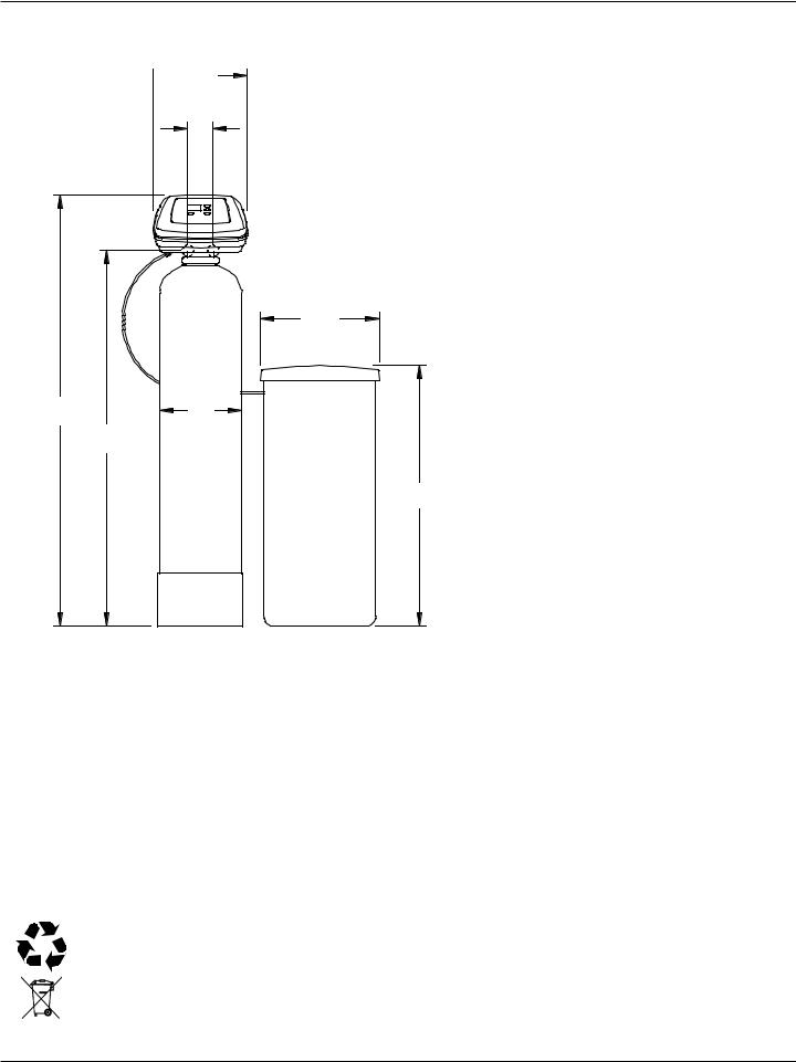
Dimensions
 14"E
14"E
3-D3/4"
OUTLETT |
INLETINLET |
INLETINLET --
OUTLETOUTLET
|
|
|
|
|
NST30ED |
NST45ED1 |
NST70ED1 |
|
|
|
|
Nominal Resin |
8” dia. |
10” dia. |
12” dia. |
Tank Size |
x 40” |
x 40” |
x 54” |
|
|
|
|
Dimension A |
48-3/4” |
50” |
65-3/4” |
Dimension B |
41-1/4” |
41-1/4” |
57” |
|
|
|
|
Dimension C |
8-1/4” dia. |
10-1/2” dia. |
12-1/4” dia. |
Dimension D |
3-3/8” |
3-3/4” |
3-3/4” |
Dimension E |
11-1/2” |
14” |
14” |
|
|
|
|
18"” DIAdia..
A |
|
C |
|
B |
|
39"”
FIG. 2
Before You Start
= The water softener requires a minimum water flow of 3 gallons per minute at the inlet. Maximum allowable inlet water pressure is 125 psi. If your house water pressure is over the maximum, install a pressure reducing valve in the water supply pipe to the system (Adding a pressure reducing valve may reduce the flow). If your home is equipped with a back flow preventer, an expansion tank must be installed in accordance with local codes and laws.
= The water softener works on 24V DC electrical power, supplied by a direct plug-in power supply (included). Be sure to use the included power supply and plug it into a nominal 120V, 60 Hz household outlet that is in a dry location only, grounded and properly protected by an overcurrent device such as a circuit breaker or fuse.
= Do not use this system to treat water that is microbiologically unsafe or of unknown quality without adequate disinfection upstream or downstream of the system.
European Directive 2002/96/EC requires all electrical and electronic equipment to be disposed of according to Waste Electrical and Electronic Equipment (WEEE) requirements. This directive or similar laws are in place nationally and can vary from region to region. Please refer to your state and local laws for proper disposal of this equipment.
4
Installation Requirements
LOCATION REQUIREMENTS
Consider all of the following when selecting an installation location for the water softener.
= Do not locate the water softener where freezing temperatures occur. Do not attempt to treat water over 120ºF. Freezing temperatures or hot water damage voids the warranty.
= To condition all water in the home, install the water softener close to the water supply inlet, and upstream of all other plumbing connections, except outside water pipes. Outside faucets should remain on hard water to avoid wasting conditioned water and salt.
= A nearby drain is needed to carry away regeneration discharge (drain) water. Use a floor drain, laundry tub, sump, standpipe, or other options (check your local codes). See "Air Gap Requirements" and "Valve Drain Requirements" sections.
= The water softener works on 24V DC electrical power, supplied by a direct plug-in power supply (included). Provide nearby a 120V, 60 Hz electrical outlet, in accordance with national and local codes.
= Always install the water softener between the water inlet and water heater. Any other installed water conditioning equipment should be installed between the water inlet and water softener (See Figure 4 below).
= Avoid installing in direct sunlight. Excessive sun heat may cause distortion or other damage to nonmetallic parts.
PLUMBING CODES
All plumbing must be completed in accordance with national, state and local plumbing codes.
In the state of Massachusetts: The Commonwealth of Massachusetts plumbing code 248-CMR shall be adhered to. A licensed plumber shall be used for this installation.
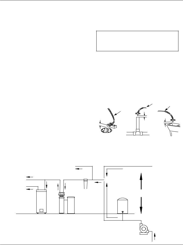
AIR GAP REQUIREMENTS
A drain is needed for regeneration water (See Figure 3). A floor drain, close to the water softener, is preferred. A laundry tub, standpipe, etc. are other drain options. Secure valve drain hose in place. Leave an air gap of 1-1/2” between the end of the hose and the drain. This gap is needed to prevent backflow of sewer water into the water softener. Do not put the end of the drain hose into the drain.
|
|
Drain |
Drain |
|
Drain |
Hose |
Hose |
|
|
|
|
1-1/2” |
Hose |
|
|
|
|
|
|
air gap |
|
|
|
|
1-1/2” |
|
|
|
air gap |
1-1/2” |
|
|
|
|
|
|
|
air gap |
|
FLOOR DRAIN |
STANDPIPE |
LAUNDRY TUB |
|
|
|
|
FIG. 3 |
THE PROPER ORDER TO INSTALL WATER TREATMENT EQUIPMENT
|
Untreated Water to |
City Water Supply |
||||
Cold Water |
Outside Faucets |
|||||
|
|
|
||||
|
|
|
|
|
||
to House |
|
|
|
|
|
|
Hot Water |
|
Optional |
Pressure |
OR |
||
to House |
|
|||||
|
Tank |
|
||||
|
|
Sediment |
|
|
|
|
|
|
Filter |
|
|
|
|
|
Water |
Water |
|
Well Water Supply |
||
|
Heater |
Softener |
|
|
|
|
|
|
|
|
Well |
|
|
|
|
|
|
Pump |
|
|
FIG. 4
5

Typical Installation Illustrations
|
MAI |
|
|
|
|
|
N W |
|
|
|
|
|
A |
|
|
|
|
|
TER PI |
|
|
|
|
Soft |
PE |
|
|
CROSSOVER |
|
|
|
|
|||
Water |
|
|
|
||
|
Hard |
Use if water supply flows from the left. |
|||
|
|
||||
|
|
Include single or 3-valve bypass. |
|||
|
|
Water |
|||
|
|
|
|
|
|
120V, |
|
|
Hard |
|
Soft |
60 Hz |
|
|
Water |
|
|
|
Hard Water to |
|
Water |
||
Outlet |
|
|
|
||
|
|
|
|
||
|
1” NPT Sweat |
outside faucets |
From |
|
To |
|
|
|
|||
|
Adaptor (2) |
|
Softener |
|
Softener |
|
not included |
|
Outlet |
|
Inlet |
|
1” NPT |
|
|
|
|
|
Installation |
|
|
|
|
|
Adaptor (2) * |
INSTALLATION USING 3-VALVE BYPASS |
|||
|
|
||||
|
O-ring Seal (2) * |
|
MAI |
|
|
|
|
|
|
|
|
|
|
|
N W |
|
|
|
|
|
|
A |
|
|
Bypass Valve * |
|
|
TER PI |
|
|
Soft |
|
|
PE |
|
|
|
|
|
|
|
|
|
Water |
|
|
|
|
|
|
BYPASS |
Hard |
|
|
Clip (4) * |
|
Valve |
Water |
|
|
Valve |
OUTLET |
|
|
|
|
INLET |
|
Valve |
|
INLET |
|
|
|
|
|
|
|
|
|
|
|
Valve |
Models NST45ED1 & NST70ED1 |
- Open the inlet and out- |
|
|
|
|
For soft water SERVICE: |
|
|
|
let valves |
1” NPT Sweat |
|
|
- Close the bypass valve |
|
|
1” NPT Sweat |
For hard water BYPASS: |
Adaptor (2) |
|
not included |
||
|
Adaptor (2) |
||
|
- Close the inlet and out- |
|
|
|
not included |
|
|
|
let valves |
|
|
|
|
|
|
|
Bypass Valve * |
- Open the bypass valve |
|
|
|
Clip (2) * |
|
|
|
|
|
|
|
|
1” NPT |
|
|
|
Installation |
|
|
|
Adaptor (2) * |
|
Valve |
|
not included |
|
|
w/ NST30ED |
|
|
INLET |
|
O-ring Seal (2) |
|
|
|
|
|
|
|
Valve |
|
|
|
INLET |
Model NST30ED |
* Included with softener. Pipe and |
FIG. 5 |
|
fittings supplied by installer. |
|||
6
Installation Instructions
1. TURN OFF WATER SUPPLY
a. Close the main water supply valve near the well pump or water meter.
b. Shut off the electric or fuel supply to the water heater.
c. Open high and low faucets to drain all water from the house pipes.
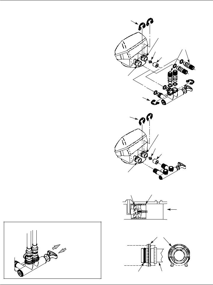
2. INSTALL BYPASS VALVE AND/OR PLASTIC INSTALLATION ADAPTORS:
a. If installing a single bypass valve, push the bypass valve, with lubricated o-ring seals in place, into the valve inlet and outlet ports (See Figures 5 & 7A/7B).
b - OR -
. If installing a 3-valve bypass system, slide plastic installation adaptors, with lubricated o-ring seals in place, into the valve inlet and outlet ports (See Figures 5 & 7A).
c. Make sure the turbine and support are firmly in place in the valve outlet, as shown in Figure 8. Blow into the valve port and observe the turbine for free rotation.
d. Snap the two large plastic clips in place on the inlet and outlet ports, from the top, down (See Figure 9). Make sure they snap into place. Pull on the bypass valve, or installation adaptors, to make sure they are held securely in place.
3. MOVE THE UNIT INTO INSTALLATION POSITION
a. Move the water softener into the desired location. Set it on a solid, level surface.
IMPORTANT: Do not place shims directly under the salt storage tank to level the softener. The weight of the tank, when full of water and salt, may cause the tank to fracture at the shim.
SINGLE BYPASS VALVE
Pull out for “Service” (Soft water)
Push in for
“Bypass”
FIG. 6
Clip (2) |
Models NST45ED1 |
|
|
& NST70ED1 |
|
|
OUTLET |
Plastic |
|
|
|
|
|
installation |
|
Turbine |
adaptors |
|
|
|
|
Support |
|
INLET |
|
|
|
|
Bypass |
Clip (2) |
|
Valve |
|
|
|
|
|
FIG. 7A |
Clip (2) |
Model NST30ED |
|
|
||
|
OUTLET |
|
|
Turbine |
|
|
Support |
|
|
|
Bypass |
|
|
Valve |
INLET |
|
FIG. 7B |
Turbine |
Turbine Support Assembly |
|
|
|
Valve Outlet |
|
|
FIG. 8 |
|
Clip |
|
SIDE VIEW |
|
END VIEW |
O-ring |
Bypass valve or |
FIG. 9 |
|
plastic adaptor |
7
Installation Instructions
Turn the bypass valve downward if connecting to floor level plumbing
INLET |
OUTLET |
FIG. 10 |
|
|
4. COMPLETE INLET AND OUTLET PLUMBING
Pipe fittings must be 3/4” minimum.
Use:
= Copper pipe = Threaded pipe
= PEX (Crosslinked Polyethylene) pipe = CPVC plastic pipe
= Other pipe approved for use with potable water IMPORTANT: Do not solder with plumbing attached to
installation adaptors and single bypass valve. Soldering heat will damage the adaptors and valve.Measure, cut, and loosely assemble pipe and fittings from the main water pipe to the inlet and outlet ports of the water softener valve. Be sure to keep fittings fully together, and pipes squared and straight.
Be sure hard water supply pipe goes to the water softener valve inlet side.
NOTE: Inlet and outlet are marked on the water softener valve. Trace the water flow direction to be sure hard water is to inlet.
IMPORTANT: Be sure to fit, align and support all plumbing to prevent putting stress on the water softener valve inlet and outlet. Stress from misaligned or unsupported plumbing may cause damage to the valve.
Complete the inlet and outlet plumbing for the type of pipe you will be using.
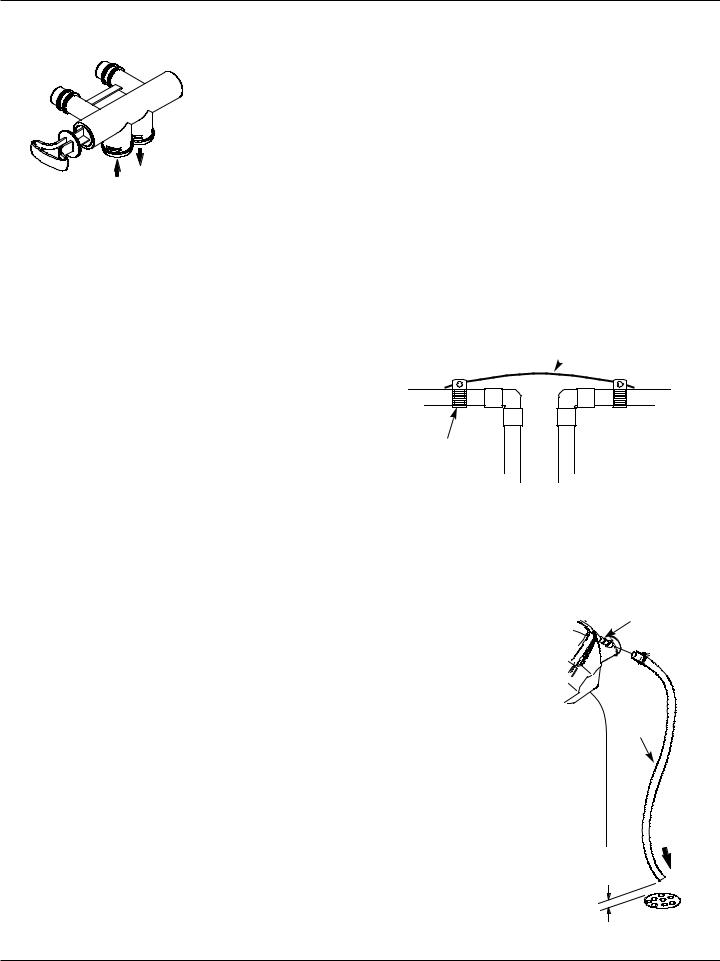
5. COLD WATER PIPE GROUNDING
The house cold water pipe (metal only) is often used as a ground for the house electrical system, The 3- valve bypass type of installation, shown in Figure 5, will maintain ground continuity. If you use a plastic bypass valve at the unit, continuity is broken. To restore the ground, do the following:
Purchase and securely install two grounding clamps and a #4 copper wire across the location where the softener will be, tightly clamping it at both ends, as shown in Figure 11.
NOTE: Check local plumbing and electrical codes for proper installation of grounding. The installation must conform to them.
Ground Wire
 (not included)
Clamp |
|
(2 - not included) |
FIG. 11 |
6. INSTALL VALVE DRAIN HOSE
a. Measure, cut to needed length and connect the 3/8" drain line (provided) to the water softener valve drain fitting. Use a hose clamp to hold the hose in place.
NOTE: Avoid drain hose
runs longer than 30 feet. Avoid elevating the hose more
than 8 feet above the floor. Make the valve drain line as
short and direct as possible.
NOTE: If codes require a rigid drain line see Figure 13.
b. Route the drain hose or copper tubing to the floor drain. Secure drain hose. This will prevent “whipping'' during regenerations. See “Air Gap Requirements" section.
8
 Loading...