


NSC22
Models
Designed, Engineered &
Assembled in the U.S.A.
NSC22 & NSC31
How to install, operate
and maintain your Demand
Controlled Water Softener
If you have any questions or concerns when
installing, operating or maintaining your
water softener, contact us at:
info@northstarwater.com
or visit www.northstarwater.com
Systems tested and certified by NSF International
against NSF/ANSI Standard 44
for hardness reduction and efficiency,
and certified to NSF/ANSI Standard 372.
Systems tested and certified by the
Water Quality Association against CSA B483.1.
Manufactured and warranted by
North Star Water Treatment Systems
1890 Woodlane Drive
Woodbury, MN 55125
Installation and Operation Manual
7371119 (Rev. D 9/4/19)

TABLE OF CONTENTS
Page
pecifications & Performance Claims . . . . . . . . . . . . . . . . . . . . . . . . . . . . . . . . . . . . . . . . . . . . . . . . . . . . . . . . . . . . 3
S
Dimensions . . . . . . . . . . . . . . . . . . . . . . . . . . . . . . . . . . . . . . . . . . . . . . . . . . . . . . . . . . . . . . . . . . . . . . . . . . . . . . . . 4
Before You Start . . . . . . . . . . . . . . . . . . . . . . . . . . . . . . . . . . . . . . . . . . . . . . . . . . . . . . . . . . . . . . . . . . . . . . . . . . . . 4
Inspect Shipment . . . . . . . . . . . . . . . . . . . . . . . . . . . . . . . . . . . . . . . . . . . . . . . . . . . . . . . . . . . . . . . . . . . . . . . . . . . . 5
ater Conditioning Information . . . . . . . . . . . . . . . . . . . . . . . . . . . . . . . . . . . . . . . . . . . . . . . . . . . . . . . . . . . . . . . . . 5
W
Installation Requirements . . . . . . . . . . . . . . . . . . . . . . . . . . . . . . . . . . . . . . . . . . . . . . . . . . . . . . . . . . . . . . . . . . . . 6-7
nstallation Instructions . . . . . . . . . . . . . . . . . . . . . . . . . . . . . . . . . . . . . . . . . . . . . . . . . . . . . . . . . . . . . . . . . . . . . 8-11
I
Programming the Water Softener . . . . . . . . . . . . . . . . . . . . . . . . . . . . . . . . . . . . . . . . . . . . . . . . . . . . . . . . . . . 12-13
Controller Features . . . . . . . . . . . . . . . . . . . . . . . . . . . . . . . . . . . . . . . . . . . . . . . . . . . . . . . . . . . . . . . . . . . . . . 14-17
Routine Maintenance . . . . . . . . . . . . . . . . . . . . . . . . . . . . . . . . . . . . . . . . . . . . . . . . . . . . . . . . . . . . . . . . . . . . . 18-19
Troubleshooting . . . . . . . . . . . . . . . . . . . . . . . . . . . . . . . . . . . . . . . . . . . . . . . . . . . . . . . . . . . . . . . . . . . . . . . . . 20-22
Wiring Schematic . . . . . . . . . . . . . . . . . . . . . . . . . . . . . . . . . . . . . . . . . . . . . . . . . . . . . . . . . . . . . . . . . . . . . . . . . . 23
Exploded View & Parts List . . . . . . . . . . . . . . . . . . . . . . . . . . . . . . . . . . . . . . . . . . . . . . . . . . . . . . . . . . . . . . . . 24-27
WATER SOFTENER WARRANTY
Warrantor: North Star Water Treatment Systems, 1890 Woodlane Drive, Woodbury, MN 55125
Warrantor guarantees, to the original owner, that:
One Year Full Warranty:
● For a period of one (1) year from the date of purchase, all parts will be free from defects in materials and workmanship and will perform their normal functions.
Limited Warranties:
● For a period of ten (10) years from the date of purchase, the salt storage tank and fiberglass mineral tank will not rust,
corrode, leak, burst, or in any other manner, fail to perform their proper functions.
● For a period of three (3) years from the date of purchase, the electronic control board and valve body will be free of
defects in materials and workmanship and will perform their normal functions.
If, during such respective period, a part proves to be defective, Warrantor will ship a replacement part directly to your
home, without charge.
General Provisions
Damage to any part of this water softener because of misuse, misapplication, neglect, alteration, accident, installation or
operation contrary to our printed instructions, or damage caused by any unusual force of nature such as, but not limited to,
freezing, flood, hurricane, tornado, or earthquake is not covered by this warranty. In all such cases, regular parts and service charges will apply.
We assume no warranty liability in connection with this water softener other than specified herein. This warranty is in lieu
of all other warranties, expressed or implied, including warranties of fitness for a particular purpose. We do not authorize
any person or representative to assume for us any other obligations on the sale of this water softener.
Should a defect or malfunction occur, contact your contractor. If you are unable to contact your contractor, return the part,
freight prepaid, directly to the factory at the address below. Enclose with the part a full description of the problem, with
your name, full address, date purchased, model and serial numbers, and selling contractor's name and address. We will
repair or replace the part and return it to you at no cost if our repair department determines it to be defective under the
terms of the warranty.
This warranty gives you specific legal rights and you may have other rights which vary from state to state.
This water softener is manufactured by
North Star Water Treatment Systems, 1890 Woodlane Drive, Woodbury, MN 55125
Questions? Contact us at: info@northstarwater.com
2

Specifications & Performance Claims
These models are efficiency rated. The efficiency rating is valid only at the minimum salt dose. These softeners
have a demand initiated regeneration (D.I.R.) feature that complies with specific performance specifications intended
o minimize the amount of regenerant brine and water used in their operation.
t
hese softeners have a rated softener efficiency of not less than 3,350 grains of total hardness exchange per pound
T
of salt (based on sodium chloride) and shall not deliver more salt than their listed rating or be operated at a sus-
ained maximum service flow rate greater than their listed rating. These softeners have been proven to deliver soft
t
water for at least ten continuous minutes at the rated service flow rate. The rated salt efficiency is measured by laboratory tests described in NSF/ANSI Standard 44. These tests represent the maximum possible efficiency that the
system can achieve. Operational efficiency is the actual efficiency after the system has been installed. It is typically
less than the rated efficiency, due to individual application factors including water hardness, water usage, and other
contaminants that reduce a softener's capacity.
Model NSC22 Model NSC31
Model Code nS22 nS31
8,700 @ 1.9 lbs.
Rated Softening Capacity (Grains @ Salt Dose)
Rated Efficiency (Grains/Pound of Salt @ Minimum Salt Dose) 4,474 @ 1.9 lbs. 5,090 @ 2.4 lbs.
Water Used During Regeneration @ Minimum Salt Dose 3.0 gal. / 1,000 grains 2.5 gal. / 1,000 grains
Total Water Used Per Regeneration @ Maximum Salt Dose 30.4 gallons 31.1 gallons
Rated Service Flow Rate 7.2 gpm 7.2 gpm
Amount of High Capacity Ion Exchange Resin 0.65 cu. ft. 0.81 cu. ft.
Pressure Drop at Rated Service Flow 13.7 psig 14.9 psig
Intermittent Flow Rate @ 15 psi* 7.6 gpm 7.3 gpm
Water Supply Max. Hardness 95 gpg 110 gpg
Water Supply Max. Clear Water Iron 6 ppm** 8 ppm**
Water Supply Pressure Limits (minimum / maximum) 20 - 125 psi (138 - 862 kPa)***
Water Temperature Limits (minimum / maximum) 40 - 120 °F (5 - 49 °C)
Minimum Water Supply Flow Rate 3 gpm (11.4 lpm)
Maximum Drain Flow Rate 2.0 gpm (7.6 lpm)
18,500 @ 6.2 lbs.
22,100 @ 10.4 lbs.
12,300 @ 2.4 lbs.
26,200 @ 7.7 lbs.
31,300 @ 12.9 lbs.
*Intermittent flow rate does not represent the maximum service flow rate used for determining the softeners’ rated
capacity and efficiency. Continuous operation at flow rates greater than the service flow rate may affect capacity
and efficiency performance.
**Capacity to reduce clear water iron is substantiated by laboratory test data. State of Wisconsin requires addi-
tional treatment if water supply contains clear water iron exceeding 5 ppm.
2
***Canada working pressure limits: 1.4 - 7.0 kg/cm
These systems conform to NSF/ANSI 44 for the specific performance claims as verified and substantiated by
test data.
Variable Salt Dose: The salt dose is selected by the electronic controls at regeneration time based on the amount
needed.
.
Questions? Contact us at: info@northstarwater.com or visit www.northstarwater.com
3
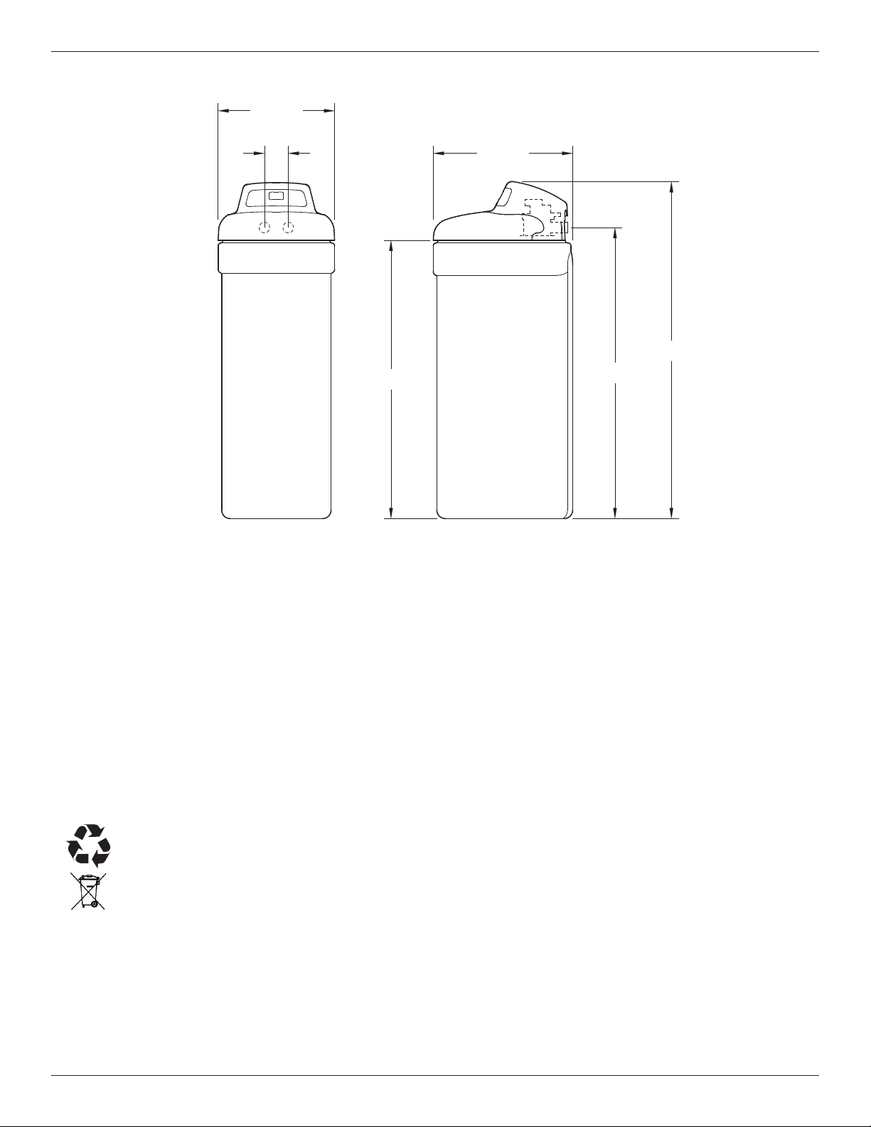
47-3/4"
41-1/2"
IN - OUT
16-1/2"
19-3/4"
40-1/4"
FRONT VIEW SIDE VIEW
OUT IN
3-3/8"
O
16-1/2”
3-3/8”
UT
Dimensions
19-3/4”
N
I
IN – OUT
47-3/4”
40-1/4”
41-1/2”
= The water softener requires a minimum water flow of 3 gallons per minute at the inlet. Maximum allowable inlet
= The water softener works on 24V DC electrical power, supplied by a direct plug-in power supply (included). Be
= Do not use this system to treat water that is microbiologically unsafe or of unknown quality without adequate dis-
European Directive 2002/96/EC requires all electrical and electronic equipment to be disposed of accord-
FRONT VIEW SIDE VIEW
FIG. 1
Before You Start
water pressure is 125 psi. If daytime pressure is over 80 psi, nighttime pressure may exceed the maximum. Use
a pressure reducing valve if necessary (Adding a pressure reducing valve may reduce the flow). If your home is
equipped with a back flow preventer, an expansion tank must be installed in accordance with local codes and laws.
sure to use the included power supply and plug it into a nominal 120V, 60 Hz household outlet that is in a dry
location only, grounded and properly protected by an overcurrent device such as a circuit breaker or fuse.
infection upstream or downstream of the system.
ing to Waste Electrical and Electronic Equipment (WEEE) requirements. This directive or similar laws are
in place nationally and can vary from region to region. Please refer to your state and local laws for proper disposal of this equipment.
4
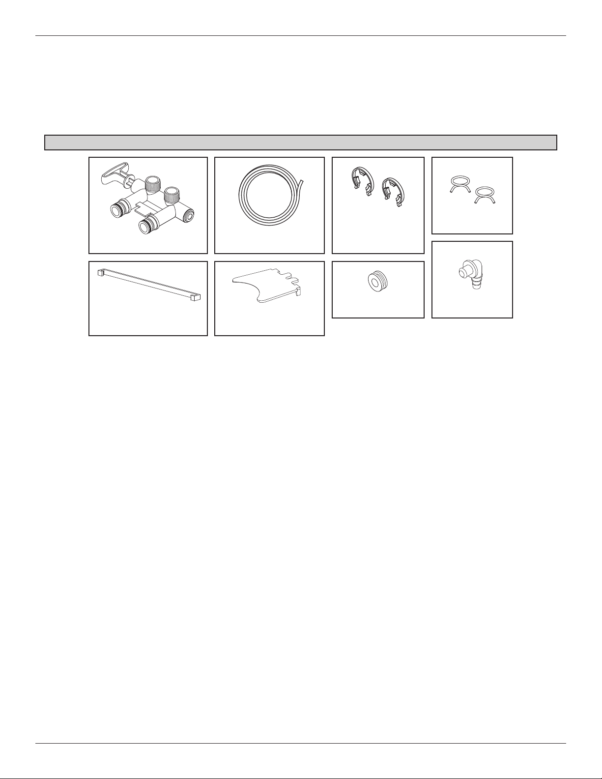
Inspect Shipment
The parts required to assemble and install the water
softener are included with the unit. Thoroughly check
the water softener for possible shipping damage and
arts loss. Also inspect and note any damage to the
p
shipping carton.
Packing List
Bypass Valve
Cover Lock
(for shipping only)
Drain Hose
Rim Insert
(for shipping only)
Remove and discard (or recycle) all packing materials.
To avoid loss of small parts, we suggest you keep the
small parts in the parts bag until you are ready to use
hem.
t
Clips
(shipped installed on
the softener’s valve)
Grommet
Hose Clamps
Adaptor Elbow
FIG. 2
Water Conditioning Information
IRON
Iron in water can cause stains on clothing and plumbing fixtures. It can negatively affect the taste of food,
drinking water, and other beverages. Iron in water is
measured in parts per million (ppm). The total* ppm of
iron, and type or types*, is determined by chemical
analysis. Four different types of iron in water are:
= Ferrous (clear water) iron
= Ferric (red water) iron
= Bacterial and organically bound iron
= Colloidal and inorganically bound iron (ferrous or
ferric)
Ferrous (clear water) iron is soluble and dissolves in
water. This water softener will reduce moderate
amounts of this type of iron (see specifications).**
Ferrous (clear water) iron is usually detected by taking
a sample of water in a clear bottle or glass.
Immediately after taking, the sample is clear. As the
water sample stands, it gradually clouds and turns
slightly yellow or brown as air oxidizes the iron. This
usually occurs in 15 to 30 minutes.
When using the softener to reduce Ferrous (clear
water) iron, add 5 grains to the hardness setting for
every 1 ppm of Ferrous (clear water) iron. See "Set
Water Hardness Number" section.
Ferric (red water), and bacterial and organically bound
irons are insoluble. This water softener will not
remove ferric or bacterial iron. This iron is visible
immediately when drawn from a faucet because it has
oxidized before reaching the home. It appears as
small cloudy yellow, orange, or reddish suspended
particles. After the water stands for a period of time,
the particles settle to the bottom of the container.
Generally these irons are removed from water by filtration. Chlorination is also recommended for bacterial
iron.
Colloidal and inorganically bound iron is of ferric or ferrous form that will not filter or exchange out of water.
This water softener will not remove colloidal iron. In
some instances, treatment may improve colloidal iron
water. Colloidal iron water usually has a yellow
appearance when drawn. After standing for several
hours, the color persists and the iron does not settle,
but remains suspended in the water.
SEDIMENT
Sediment is fine, foreign material particles suspended
in water. This water softener will not remove sediment. This material is most often clay or silt. Extreme
amounts of sediment may give the water a cloudy
appearance. A sediment filter installed upstream of
the water softener normally corrects this situation.
* Water may contain one or more of the four types of
iron and any combination of these. Total iron is the
sum of the contents.
** Capacity to reduce clear water iron is substantiated
by laboratory test data.
5
Installation Requirements
LOCATION REQUIREMENTS
Consider all of the following when selecting an installation location for the water softener.
Do not locate the water softener where freezing
=
temperatures occur. Do not attempt to treat water
over 120ºF. Freezing temperatures or hot water
damage voids the warranty.
= To condition all water in the home, install the water
softener close to the water supply inlet, and
upstream of all other plumbing connections, except
outside water pipes. Outside faucets should remain
on hard water to avoid wasting conditioned water
and salt.
= A nearby drain is needed to carry away regenera-
tion discharge (drain) water. Use a floor drain,
laundry tub, sump, standpipe, or other options
(check your local codes). See "Air Gap
Requirements" and "Valve Drain Requirements"
sections.
= The water softener works on 24V DC electrical
power, supplied by a direct plug-in power supply
(included). Provide nearby a 120V, 60 Hz electrical
outlet in accordance with NEC and local codes.
= Always install the water softener between the water
inlet and water heater. Any other installed water
conditioning equipment should be installed between
the water inlet and water softener (See Figure 4
below).
= Avoid installing in direct sunlight. Excessive sun
heat may cause distortion or other damage to nonmetallic parts.
PLUMBING CODES
All plumbing must be completed in accordance with
national, state and local plumbing codes.
In the state of Massachusetts: The Commonwealth
of Massachusetts plumbing code 248-CMR shall
be adhered to. A licensed plumber shall be used
for this installation.
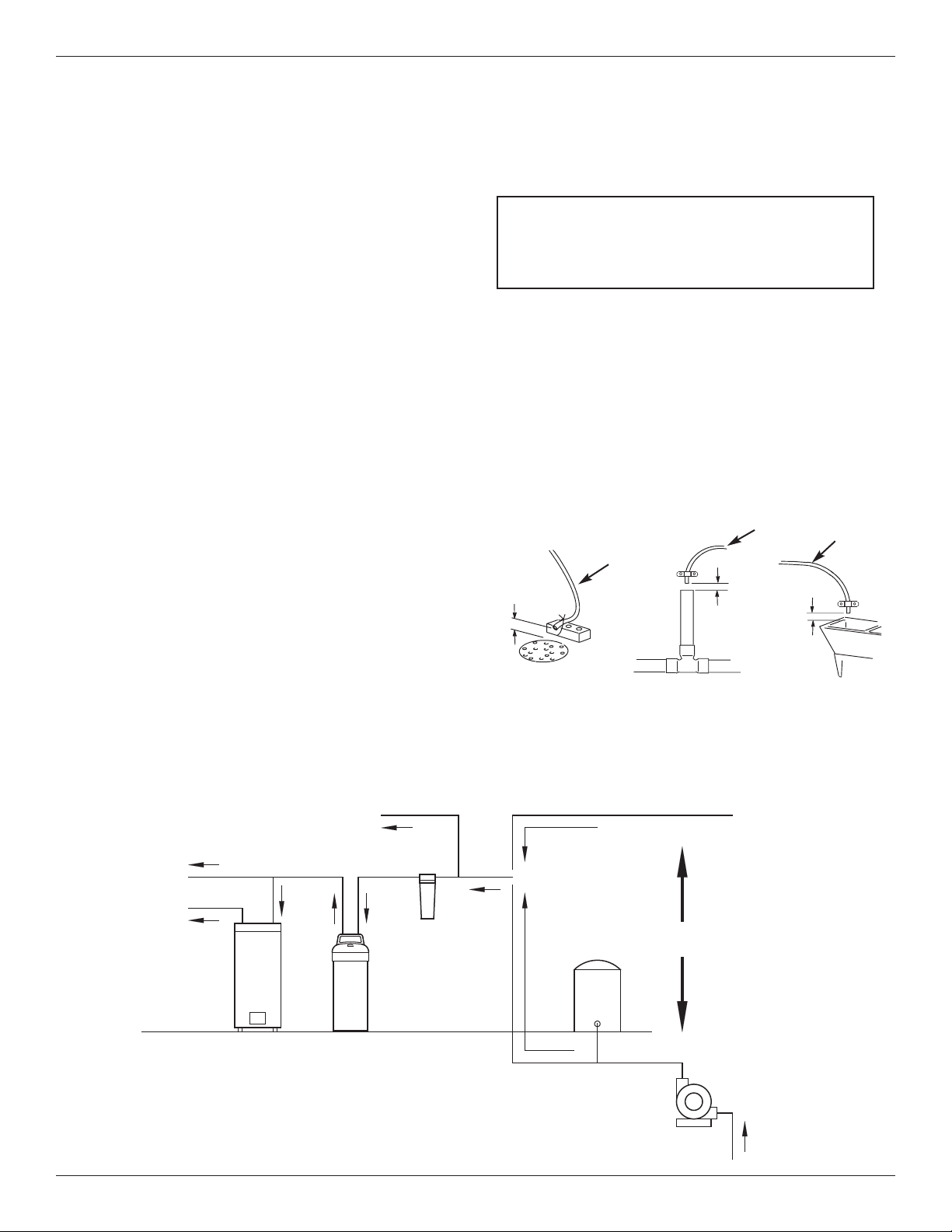
AIR GAP REQUIREMENTS
A drain is needed for regeneration water (See Figure
3). A floor drain, close to the water softener, is preferred. A laundry tub, standpipe, etc. are other drain
options. Secure valve drain hose in place. Leave an
air gap of 1-1/2” between the end of the hose and the
drain. This gap is needed to prevent backflow of
sewer water into the water softener. Do not put the
end of the drain hose into the drain.
1-1/2”
air gap
FLOOR DRAIN
Drain
Hose
1-1/2”
air gap
Drain
Hose
1-1/2”
air gap
LAUNDRY TUBSTANDPIPE
Drain
Hose
FIG. 3
THE PROPER ORDER TO INSTALL WATER TREATMENT EQUIPMENT
Cold Water
to House
Hot Water
to House
Untreated Water to
Outside Faucets
Water
Heater
Water
Softener
Optional
Sediment
Filter
City Water Supply
Pressure
Tank
Well Water Supply
OR
Well
Pump
FIG. 4
6
Installation Requirements
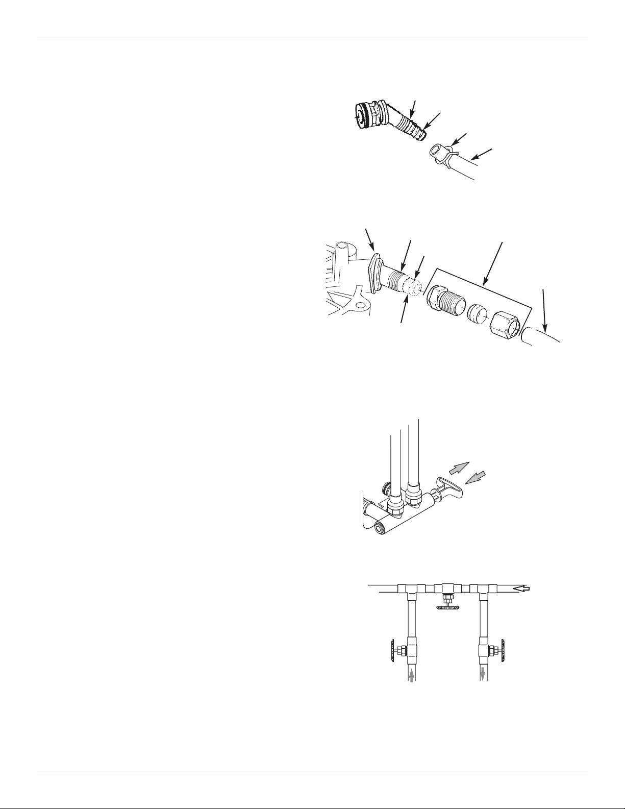
VALVE DRAIN REQUIREMENTS
Using the flexible drain hose (included), measure and
cut to the length needed. Flexible drain hose is not
allowed in all localities (check your plumbing codes). If
local codes do not allow use of a flexible drain hose, a
rigid valve drain run must be used. Purchase a compression fitting (1/4 NPT x 1/2 in. minimum tube) and
1/2" tubing from your local hardware store. Plumb a
rigid drain as needed (See Figure 6).
NOTE: Avoid drain hose runs longer than 30 feet.
Avoid elevating the hose more than 8 feet
above the floor. Make the valve drain line as
short and direct as possible.
1/4” NPT
Thread
Clip
Cut barbs from drain fit-
ting (pull clip to remove
1/4 NPT
Threads
Barbs
fitting from valve)
Barbs for 3/8”
I.D. Tubing
Hose Clamp
Drain Hose
FIG. 5
Compression Fitting.
1/4 NPT x 1/2” O.D.
Tube (not included)
1/2” Outside Dia.
Copper Tube
(not included)
FIG. 6
INLET / OUTLET PLUMBING OPTIONS
Always install either a single bypass valve (provided),
as shown in Figure 7, or, if desired, parts for a 3 valve
bypass system (not included) can be purchased and
assembled, as shown in Figure 8. Bypass valves
allow you to turn off water to the softener for maintenance if needed, but still have water in house pipes.
Use:
= Copper pipe
= Threaded pipe
= PEX (Crosslinked Polyethylene) pipe
= CPVC plastic pipe
= Other pipe approved for use with potable water
IMPORTANT: Do not solder with plumbing attached to
the single bypass valve. Soldering heat
will damage the plastic valve.
Outlet
Valve
SINGLE BYPASS VALVE
Pull out for “Service”
(Soft water)
Push in for
“Bypass”
3 VALVE BYPASS
Bypass
Valve
From Water
Softener
To Water
Softener
FIG. 7
Inlet
Valve
FIG. 8
7
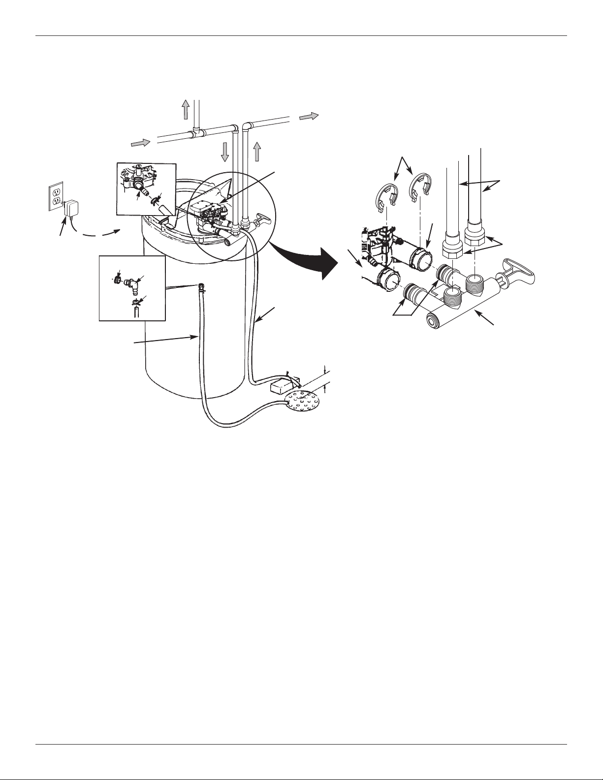
Installation Instructions
TYPICAL INSTALLATION
Hard Water
To
Controller
Plug-in
Power
Supply
Salt Storage Tank
Overflow Hose*
*Do not connect the
water softener valve
drain hose to the salt
storage tank overflow
hose.
rommet
G
To Outside
alve
V
rain
D
Faucets
ose
H
Clamp
rain
D
Elbow
Hose
Clamp
e
p
i
P
r
e
t
a
W
n
i
a
M
Water Softener
Valve
Valve Drain
Hose*
Secure Valve Drain Hose
in place over Floor Drain
Floor Drain
onditioned
C
Water
Inlet
Lubricated
1-1/2”
air gap
Clips
Pipes
Outlet
O-rings
NOTE: See “Air Gap Requirements” section.
NOTE: Water Softener shown with Salt Lid
and Top Cover removed
1” NPT Sweat
Adaptors (not
included)
Single
Bypass Valve
FIG. 9
TURN OFF WATER SUPPLY
1. Close the main water supply valve, located near the
well pump or water meter.
2. Shut off the electric or fuel supply to the water heater.
3. Open all faucets to drain all water from house pipes.
NOTE: Be sure not to drain water from the water
heater, as damage to the water heater elements could result.
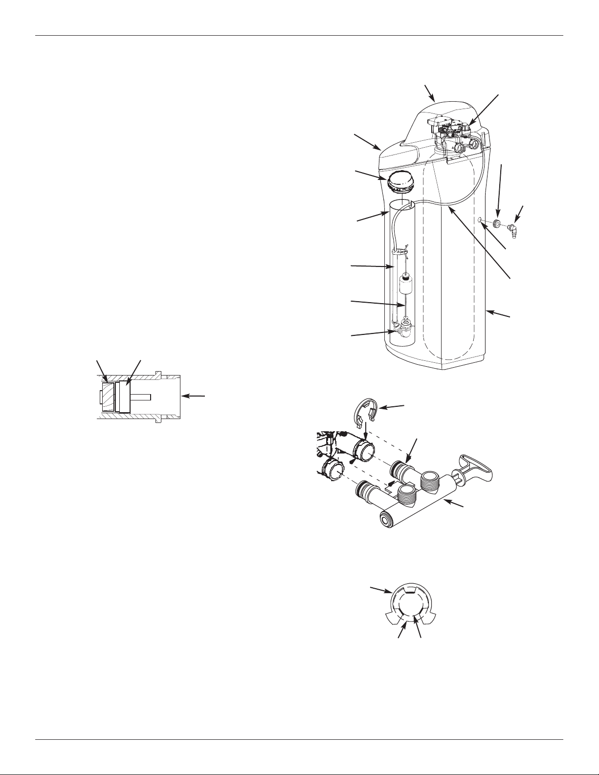
ASSEMBLY
1. North Star models are factory assembled. During
installation, unsnap and remove the top cover,
together with the salt lid, to expose the softener
valve assembly. Set them aside to prevent damage.
Check the brinewell to be sure it is secured and vertical (See Figure 11).
2. Install the brine tank overflow grommet and elbow
into the 13/16” diameter hole in the back of the salt
storage tank wall.
MOVE THE UNIT INTO PLACE
1. Move the water softener into the desired location.
Set it on a solid, level surface.
IMPORTANT: Do not place shims directly under the salt
storage tank to level the softener. The
weight of the tank, when full of water and
salt, may cause the tank to fracture at the
shim.
2. Visually check and remove any debris from the water
softener valve inlet and outlet ports. Carefully remove
the two large plastic clips (you will use them).
3. Make sure the turbine assembly spins freely in the
"out" port of the valve (See Figure 10).
4. If not already done, put a light coating of silicone
grease on the single bypass valve o-rings.
5. Push the single bypass valve into the softener valve
as far as it will go. Snap the two large holding clips
into place, from the top down as shown in Figures 12
& 13.
IMPORTANT: Be sure the clips snap firmly into place so
the single bypass valve will not pull out.
8
Installation Instructions
COMPLETE INLET AND OUTLET PLUMBING
Measure, cut, and loosely assemble pipe and fittings
from the main water pipe to the inlet and outlet ports of
he water softener valve. Be sure to keep fittings fully
t
together, and pipes squared and straight.
Be sure hard water supply pipe goes to the water softener valve inlet side.
NOTE: Inlet and outlet are marked on the water sof-
tener valve. Trace the water flow direction to
be sure hard water is to inlet.
IMPORTANT: Be sure to fit, align and support all
plumbing to prevent putting stress on
the water softener valve inlet and outlet.
Undue stress from misaligned or unsupported plumbing may cause damage to
the valve.
Complete the inlet and outlet plumbing for the type of
pipes you will be using.
Turbine
Turbine Support Assembly
Salt Lid
Brinewell
over
C
Brinewell
Stand
Tube
Float
Stem
Brine
Valve
Top Cover
Nozzle & Venturi
Assembly
Brine Tank
Overflow
Grommet
Brine Tank
Overflow
Elbow
13/16” Hole
Brine
Tubing
Salt
Storage
Tank
FIG. 11
Valve Outlet
FIG. 10
Correct Assembly
Clip
Outside diameter
of water softener
valve inlet & outlet
Clip
Channel
Outside diameter
of clip channel on
single bypass valve
Single Bypass Valve
FIG. 12
FIG. 13
NOTE: Be sure all 3 tabs of the clip go through the matching
holes on the water softener valve inlet or outlet, and
fully into the channel on the single bypass valve.
Make sure that the tabs are fully seated.
9
 Loading...