


 Loading...
6000i NETWORKED NAVIGATION SYSTEM
INSTALLATION MANUAL
Revision G
Part Number GM6KIM
Northstar |
www.NorthstarNav.com |
|
a unit of Brunswick New Technologies Marine Electronics |
||
Service: 978/897-6600 |
||
30 Sudbury Road |
||
Acton, Massachusetts 01720 |
Sales: 800/628-4487 |
Contents
SECTION ONE: Introducing the 6000i |
|
- |
- |
- |
- |
- |
- |
- |
- |
- |
- |
- |
- |
- |
- |
- |
- |
1 |
|||||
Checking the 6000i package |
|
- |
- |
- |
- |
- |
- |
- |
- |
- |
- |
- |
- |
- |
- |
- |
- |
- |
- |
1 |
|||
SECTION TWO: Installing and wiring the 6000i |
- |
- - - - - - - |
- |
- |
- |
- |
5 |
||||||||||||||||
Bench-testing the 6000i - - - - - - - - - - - - - - - - |
- |
- |
- |
- |
5 |
||||||||||||||||||
Mounting the 6000i |
- |
- |
- |
- |
- |
- |
- |
- |
- |
- |
- |
- |
- |
- |
- |
- |
- |
- |
- |
- |
- |
- |
5 |
Wiring the 6000i - |
- - |
- |
- |
- |
- |
- |
- |
- |
- |
- |
- |
- |
- |
- |
- |
- |
- |
- |
- |
- |
- |
- |
8 |
SECTION THREE: Installing and wiring the antenna |
|
- |
- |
- |
- |
- |
- |
- |
- |
- |
13 |
||||||||||||
Choosing the best mounting location |
|
- |
- |
- |
- |
- |
- |
- |
- |
- |
- |
- |
- |
- |
|
13 |
|||||||
Mounting and wiring the AN150-P antenna |
|
- |
- |
- |
- |
- |
- |
- |
- |
- |
- |
|
15 |
||||||||||
SECTION FOUR: Networking the Northstar 6000i |
- - - - - - - |
- |
- |
- |
17 |
||||||||||||||||||
Restrictions on networking - - - - - - - - - - - - - - - - - - |
|
18 |
|||||||||||||||||||||
Connecting a network of two devices |
|
- |
- |
- |
- |
- |
- |
- |
- |
- |
- |
- |
- |
- |
|
19 |
|||||||
Connecting a network of more than devices |
|
- |
- |
- |
- |
- |
- |
- |
- |
- |
- |
|
19 |
||||||||||
Networking setup - - - - - - - - - - - - |
- |
- |
- |
- |
- |
- |
- |
- |
- |
- |
|
17 |
|||||||||||
SECTION FIVE: Checking out the system |
|
- |
- |
- |
- |
- |
- |
- |
- |
- |
- |
- |
- |
- |
- |
27 |
|||||||
Turning the 6000i on and off |
|
- |
- |
- |
- |
- |
- |
- |
- - - - - - - |
- |
- |
- |
|
27 |
|||||||||
Checking satellite status - - - - - - - - - - - - - - - - |
- |
- |
- |
|
27 |
||||||||||||||||||
Checking DGPS status - - - - - - - - - - - - - - - - - - - - |
|
28 |
|||||||||||||||||||||
Installation-test checklist - - - - - - - - - - - - - - - - |
- |
- |
- |
|
28 |
||||||||||||||||||
SECTION SIX: Interfacing the 6000i system |
- |
- |
- |
- - - - - - - |
- |
- |
- |
31 |
|||||||||||||||
The NMEA connector - - - - - - - - - - - - - - - - - - - - |
|
32 |
|||||||||||||||||||||
Configuring the RS-232 port |
|
- |
- |
- |
- |
- |
- |
- |
- |
- |
- |
- |
- |
- |
- |
- |
- |
- |
|
38 |
|||
Using the Aux Port |
- - |
- |
- |
- |
- |
- |
- |
- |
- |
- |
- |
- |
- |
- |
- |
- |
- |
- |
- |
- |
- |
|
39 |
Connecting the 6000i to a remote display |
|
- |
- |
- |
- |
- |
- |
- |
- |
- |
- |
- |
|
43 |
|||||||||
Connecting the 6000i to a video camera |
- |
- |
- - - - - - - |
- |
- |
- |
|
43 |
|||||||||||||||
SECTION SEVEN: Troubleshooting and servicing the 6000i system |
|
- |
- |
45 |
|||||||||||||||||||
Troubleshooting installation problems |
- |
- |
- |
- |
- |
- |
- |
- |
- |
- |
- |
- |
- |
|
45 |
||||||||
Getting technical support |
- |
- |
- |
- |
- |
- |
- |
- |
- |
- |
- |
- |
- |
- |
- |
- |
- |
- |
- |
|
47 |
||
APPENDIX A: 6000i system technical specifications |
|
- |
- |
- |
- |
- |
- |
- |
- |
- |
51 |
||||||||||||

SECTION ONE: Introducing the
6000i
Checking the 6000i package
The Northstar 6000i is a networked color GPS navigation family that you can connect to a wide variety of optional equipment, including the Northstar 491
echo sounder, Northstar radar, and VGA displays. Other optional interfaces include any NTSCor PAL-compatible video sources, such as a video camera, TV, DVD, or VCR. For installation instructions for the Northstar 491 or Northstar radar, see the Northstar 491 Installation Manual (P/N GM495) or the Northstar Radar Installation Manual (P/N GMKRadIM or GMRad2KIM).
Table 1: 6000i parts list
|
|
|
|
|
|
|
Qty |
Part name |
|
|
Part number |
|
|
|
|
|
|
|
|
|
|
|
6.4” unit |
8.4” unit |
10.4” unit |
12” Unit |
15” unit |
|
|
|
|
|
|
|
|
|
|
|
|
|
|
1 |
6000i unit |
6K6 |
6K8 |
6K10 |
6K12 |
6K15 |
|
|
|
|
|
|
|
1 |
Flush-mount hardware kit |
6K6FM-A |
6K8FM-A |
6K10FM-A |
6K12FM-A |
6K15FM-A |
|
|
|
|
|
|
|
1 |
Flush-mount gasket |
— |
— |
— |
HG420 |
HG412 |
|
|
|
|
|
|
|
1 |
Flush-Mounting Template |
GT6K6 |
GT6K8 |
GT6K10 |
GT6K12 |
GT15 |
|
|
|
|
|
|
|
1 |
Yoke-mount kit |
6K6YM-A |
6K8YM-A |
6K10YM-A |
— |
— |
|
|
|
|
|
|
|
1 |
Sunshield |
XP793 |
XP784 |
XP789 |
XP821 |
XP817 |
|
|
|
|
|
|
|
1 |
WAAS/GPS antenna and cable |
|
AN150-P (AN-156-P Optional) |
|
||
|
|
|
|
|
|
|
1 |
TNC connector for antenna cable |
— |
— |
— |
— |
KC285 |
|
|
|
|
|
|
|
1 |
10-foot power cable with 7-amp fuse |
|
|
WA535-B |
|
|
|
|
|
|
|
|
|
1 |
10-foot NMEA interface cable |
|
|
WA215 |
|
|
|
|
|
|
|
|
|
1 |
Connector dust cover |
|
|
KC398 |
|
|
|
|
|
|
|
|
|
1 |
Northstar 6000i Installation Manual |
|
|
GM6KIM |
|
|
|
|
|
|
|
|
|
1 |
Northstar 6000i Operator’s Manual |
|
|
GM6KUM |
|
|
|
|
|
|
|
|
|
1 |
Quick Pocket Reference |
— |
— |
— |
GM6K12QR |
— |
|
|
|
|
|
|
|
1 |
Owner registration card |
|
|
GD671 |
|
|
|
|
|
|
|
|
|
1 |
Limited Warranty Statement |
|
|
GD683 |
|
|
|
|
|
|
|
|
|
1 |
Navionics slip sheet |
|
|
GM988 |
|
|
|
|
|
|
|
|
|
1 |
Parts kit (see next page) |
|
6K-PK |
|
15-PK |
|
|
|
|
|
|
|
|
6000i Installation Manual, Rev. G |
Page 1 |

SECTION ONE: Introducing the 6000i
To connect multiple units using Northstar’s N2 technology, Ethernet cables must be purchased separately (see ”SECTION FOUR: Networking the Northstar 6000i” starting on page 17).
Table 2: Parts Kit contents for 6.4”, 8.4”, and 10.4” 6000i |
(P/N 6K-PK) |
|||
|
|
|
|
|
Qty |
Part name |
|
|
Part number |
|
|
|
|
|
1 |
Spare fuse (7A fast-blow 5 x 20mm) |
|
|
FF211 |
|
|
|
|
|
4 |
Hex nut, 6-32, for flush-mounting |
|
|
HN300 |
|
|
|
|
|
4 |
Threaded stud, 6-32, for flush mounting |
|
HS610 |
|
|
|
|
|
|
4 |
Lockwasher, # 6, for flush mounting |
|
|
HW300 |
|
|
|
|
|
4 |
Flat washer, #6, for flush mounting |
|
|
HW405 |
|
|
|
|
|
1 |
TNC connector for antenna cable |
|
|
KC285 |
|
|
|
|
|
Table 3: Parts Kit contents for 12-inch 6000i |
(P/N 6K12-PK) |
|||
|
|
|
|
|
Qty |
Part name |
|
|
Part number |
|
|
|
|
|
1 |
Spare fuse (7A fast-blow 5 x 20mm) |
|
|
FF211 |
|
|
|
|
|
12 |
Hex nut, 8-32, for flush-mounting |
|
|
HN421 |
|
|
|
|
|
12 |
Threaded stud, 8-32 x 2 1/4, for flush |
|
|
HS605 |
|
mounting |
|
|
|
|
|
|
|
|
12 |
Lockwasher, #8, for flush mounting |
|
|
HW400 |
|
|
|
|
|
12 |
Flat washer, #8, for flush mounting |
|
|
HW405 |
|
|
|
|
|
1 |
TNC connector for antenna cable |
|
|
KC285 |
|
|
|
|
|
Table 4: Parts Kit contents for 15-inch 6000i |
(P/N 15-PK) |
|||
|
|
|
|
|
Qty |
Part name |
|
|
Part number |
|
|
|
|
|
1 |
Spare fuse (7A fast-blow 5 x 20mm) |
|
|
FF211 |
|
|
|
|
|
12 |
Hex nut, 8-32, for flush-mounting |
|
|
HN421 |
|
|
|
|
|
12 |
Threaded stud, 8-32 x 2 1/4, for flush |
|
|
HS605 |
|
mounting |
|
|
|
|
|
|
|
|
12 |
Lockwasher, #8, for flush mounting |
|
|
HW400 |
|
|
|
|
|
12 |
Flat washer, #8, for flush mounting |
|
|
HW405 |
|
|
|
|
|
1 |
TNC connector for antenna cable |
|
|
KC285 |
|
|
|
|
|
Page 2 |
6000i Installation Manual, Rev. G |

SECTION ONE: Introducing the 6000i
Table 5: 6000i Optional equipment
|
|
Part name |
Part number |
|
|
Ethernet cables |
See Section 4 |
|
|
Remote control and batteries |
6KRMC-A |
|
|
Spare batteries for remote control |
BL134 |
|
|
Additional antenna cable |
WC255 or WC263 |
|
|
Northstar Echosounder |
|
|
|
Northstar Radar |
|
|
|
6000i Installation Manual, Rev. G |
Page 3 |

SECTION ONE: Introducing the 6000i
Page 4 |
6000i Installation Manual, Rev. G |

SECTION TWO: Installing and wiring the 6000i
WARNING! Before starting the installation, be sure to turn electrical power off. If power is left on or turned on during the installation, fire, electrical shock, or other serious injury may occur.
Be sure that the voltage of the power supply is compatible with the 6000i’s voltage rating of 10 to 36 volts DC. Connecting to the wrong power supply can cause fire or damage to the equipment.
Be sure to ground the equipment to prevent electrical shock and mutual interference.
Be sure to use a 7-amp fast-blow fuse in the supplied power cable. Using the wrong fuse can cause fire or damage to the 6000i.
Bench-testing the 6000i
Northstar recommends bench-testing the 6000i with a GPS antenna before installing it onto the vessel. Bench testing ensures that the equipment is fully operational, and lets the unit collect the current almanac and ephemeris data and a local position fix, which results in less on-board installation time.
Mounting the 6000i
CAUTION! Proper installation of the Northstar 6000i is critical to accurately receive and effectively use GPS/WAAS signals under a wide variety of weather conditions.
Keep the following safe compass distance from the 6000i: 1.0m standard, 0.8m steering.
Choosing the best mounting location
Choose the mounting location carefully before you drill or cut. The 6000i should be installed in an accessible, dry location where the operator can easily use the controls and clearly see the display screen. Be sure to leave a direct path for all of the cables. The display screen is high-contrast and anti-reflective, and is viewable in direct sunlight, but for best results, install the 6000i out of direct sunlight. The chosen location should have minimal glare from windows or bright objects. If the 6000i is yoke-mounted low, tilt the unit back for best viewing contrast.
6000i Installation Manual, Rev. G |
Page 5 |

SECTION TWO: Installing and wiring the 6000i
Mounting dimensions
Figures 1 – 5 show the overall unit dimensions.

 1.8
1.8 
 3.12
3.12 
Dimensions in inches
 1.8
1.8 
 3.12
3.12 
10.1
9.1
6.4" 6.25
7.5
Figure 1: Dimensions (6.4” unit)
12 
11
8.4" |
7.6 |
9 |
|
Dimensions in inches
Figure 2: Dimensions (8.4” unit)
1.8 |
|
|
|
|
|
|
|
|
|
|
|
13.5 |
|
|
|
|
|
|
|
|
|
|
|
|
|
|
|
|
|
|
|||
|
|
|
|
|
|
|
|
|
|
|
|
|
|
|
|
|
|
|
|
|
|
|
|
|
|
|
|
|
|
|
|
|
|
|
|
|
|
3.12 |
|
|
|
|
|
|
|
|
|
|
|
|
|
|
|
|
|
|
|
|
|
|
|
|
|
12.5 |
|
|
|
|
|
|
|
|
|
|
|
|
|
|
|
|
|
|
|
|
|
|
|
|
|
|
|
|
|
|
|
|
|
||||
|
|
|
|
|
|
|
|
|
|
|
|
|
|
|
|
|
|
|
|
|
|
|
|
|
|
|
|
|
|
|
|
|
|
|
|
|
|
|
|
|
|
|
|
|
|
|
|
|
|
|
|
|
|
|
|
|
|
|
|
|
|
|
|
|
|
|
|
10.4" 8.75
9.75
Dimensions in inches
Figure 3: Dimensions (10.4” unit)
Page 6 |
6000i Installation Manual, Rev. G |
10.5
4.4
Dimensions in inches
Dimensions in inches
SECTION TWO: Installing and wiring the 6000i
14.0
12" 10.5
Figure 4: Dimensions (12” unit)
(Flush-mount only)

|
|
Figure 5: Dimensions (15” unit)
(Flush-mount only)
Flush-mounting
When flush mounting, leave sufficient clearance space behind the unit for all of the cables and connectors. Clearance is also required on the right side of the unit for opening the chart cartridge door (not necessary for the 12” or 15” units). Flush mounting requires good ventilation behind the mounting panel. Poor ventilation may cause the 6000i to overheat, which, in turn, will cause the screen brightness to dim. For overall width and height requirements, see the Northstar 6000i
6000i Installation Manual, Rev. G |
Page 7 |
SECTION TWO: Installing and wiring the 6000i
Flush-Mounting Template, which you can use to drill the mounting holes and cut the mounting panel in the exact recommended locations.
CAUTION! When flush mounting, be sure to mount the 6000i on a flat surface. Mounting on a curved surface can result in water leaks. Do not overtighten the mounting screws; you may damage the case and compromise its waterproof seal. This type of physical damage will void the warranty.
Use the supplied flush-mount template to cut the hole for the 6000i, and use the supplied gasket between the 6000i and the instrument panel to help seal against water penetration. The use of anti-seize compound on the flush-mount studs and nuts is recommended.
The parts kit contains the appropriate number of threaded studs, flat washers, lock washers, and hex nuts for flush mounting.
Yoke-mounting
For recommended mounting clearances, see Figures 1 – 3 on the previous pages. Leave additional clearance for opening the cartridge door on the right side of the unit. The 12inch and 15-inch models are designed for flush-mounting only.
When yoke-mounting, the four plastic “poker chips” are inserted into the holes in the unit and the yoke. It may be helpful to apply a dab of RTV or other adhesive to keep them in place during installation, especially if the unit will be removed and replaced frequently.
Wiring the 6000i
Avoiding cable wiring shortcuts
Most installation problems are caused by shortcuts taken with system cables. When wiring the 6000i, follow the guidelines below.
DON’T DO THIS!
•Don’t make sharp bends in the cables
•Don’t run cables in a way that allows water to flow down into the connectors
DO THIS!
•Do make drip and service loops
•Do tie-wrap all cables to keep them secure
•If cables are shortened, lengthened, or re-terminated, do seal and protect all wiring connections
•Do leave room at the back to install and remove cables
Page 8 |
6000i Installation Manual, Rev. G |
SECTION TWO: Installing and wiring the 6000i
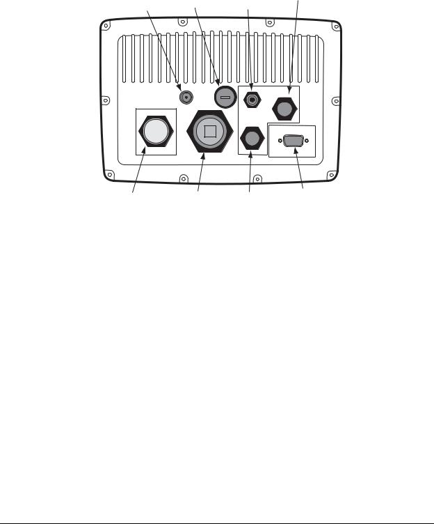
The interface connectors
Interface connectors are shown in Figure 6: ”Interface connectors,” below. The functions of these connectors are described in Table 6. Interfacing is described in detail in Section Six, beginning on page 31.
NTSC |
FUSE |
|
GPS |
POWER |
||
VIDEO |
|
|||||
(7 Amp) |
|
ANTENNA |
||||
|
|
|||||
INPUT |
|
|
||||
|
|
|
|
|
|
|
|
|
|
|
|
|
|
|
|
|
|
|
|
|
|
|
|
|
|
|
|
|
|
|
|
|
|
|
NMEA |
ETHERNET |
AUX |
VGA |
|
(video out) |
||||
|
|
|
REAR VIEW OF 6000i
6.4" unit shown (all units use same connector layout)
Figure 6: Interface connectors
Table 6: Interface connector functions
|
|
|
Connector name |
Connector function(s) |
Connects to... |
|
|
|
NMEA |
NMEA Port 1 input/output |
NMEA devices: autopilot, heading |
(18-pin connector) |
|
sensor, etc. |
|
|
|
|
NMEA Port 2 input/output |
Same as NMEA Port 1, or Northstar |
|
|
radar |
|
|
|
|
RS-232 Port |
SC-104, NMEA devices, or remote |
|
|
power control |
|
|
|
|
Honk alarm/200 ppnm |
Remote honk alarm, or speed |
|
|
indicator |
|
|
|
Ethernet |
N2 Networking |
Another 6000i or other |
(RJ-45) |
|
N2-compatible device (N2 is |
|
|
Northstar’s proprietary format) |
|
|
|
GPS |
GPS antenna input |
AN150-P GPS antenna |
(TNC coaxial 50 Ohm) |
|
|
|
|
|
6000i Installation Manual, Rev. G |
Page 9 |

SECTION TWO: Installing and wiring the 6000i
Table 6: Interface connector functions (continued)
|
|
|
Connector name |
Connector function(s) |
Connects to... |
|
|
|
AUX |
RS-422/NMEA input/output |
Northstar 491 echo sounder, or |
(6-pin connector) |
|
older Northstar units for database |
|
|
transfer |
|
|
|
POWER (3-pin |
Power input |
10 to 36 VDC, 30 watts |
connector) |
|
|
|
|
|
VGA (15-pin D |
Video output |
Remote display |
connector) |
|
|
|
|
|
NTSC VIDEO INPUT |
Video input |
Any NTSC-compatible video source |
(BNC coaxial 75 Ohm) |
|
|
|
|
|
Electrical power requirements
The 6000i is a negative-ground system that’s reverse-polarity protected. Power requirement is 10 VDC minimum to 36 VDC maximum, using at least 16-gauge connecting wire.
CAUTION! To protect the power wiring, Northstar strongly recommends that you connect the 6000i to a circuit breaker or 7-amp fuse located at the power source (battery or switch panel).
Connecting the 6000i to ship’s power
The 6000i is shipped with a 10-foot power cable that you can lengthen to a maximum of 25 feet:
•for a cable length up to 15 feet, use 16-gauge wire or heavier
•for a cable length from 15 to 25 feet, use 14-gauge wire or heavier
If you lengthen the power cable, use an external fuse at the battery end as an added safety precaution. The fuse size should be chosen to be appropriate for the size of the smallest conductor in the circuit. See the NMEA or American Boating and Yachting Counsel specifications to find the correct fuse for your wiring.
For the best protection from noise, connect the power wiring directly to the battery or dedicated electronics bus. The green ground wire should be connected directly to ship’s ground. The power cable has an inline fuse to protect the vessel’s wiring, and prevent electrical fires and damage to the unit. If you shorten or lengthen this cable, be sure to keep the inline fuse intact (or provide circuit breaker protection).
Spare in-line fuses are not supplied with the unit and should be purchased locally to avoid loss of function.
Page 10 |
6000i Installation Manual, Rev. G |

SECTION TWO: Installing and wiring the 6000i
Connect the wires in the power cable as follows.
•red → positive (+)
•black → negative (–)
•green → ship’s ground
NOTE: Grounding the 6000i to the vessel usually reduces interference. Without an earth grounding, performance may be reduced. Secure the green wire to the vessel’s nearest grounding point. If a noise-free earth grounding point isn’t available, cap and insulate the green wire—it shouldn’t be used when an earth ground isn’t available, or with systems using “floating” grounds.
6000i Installation Manual, Rev. G |
Page 11 |

SECTION TWO: Installing and wiring the 6000i
Page 12 |
6000i Installation Manual, Rev. G |

SECTION THREE: Installing and wiring the antenna
Choosing the best mounting location
Before you drill or cut, choose a mounting location that meets the following criteria. The antenna should be mounted:
•where there’s enough mounting clearance to easily connect the cable
•low on the vessel, and near the center, since motion caused by the vessel’s roll, pitch and yaw can degrade speed-over-ground (SOG) and course-over-ground (COG) readings
•away from the radiation plane of any INMARSAT or radar antennas, and away from any other high-power transmitting antennas (see Figure 8 on page 14)
•high enough to provide an unblocked view of the sky in all directions, minimizing or eliminating any obstructions that block the antenna’s view of the sky (the system can use satellites down to the horizon)
•away from masts or objects that could “shadow” the antenna
To avoid mutual interference among different antennas on the vessel, see the recommendations in Figure 8 below. This figure shows the minimum distances that should separate GPS/WAAS antennas from other antennas and physical mounting surfaces. Normally, these guidelines produce a relatively trouble-free installation; however, since every installation is unique, you may want to adjust these distances to the particular equipment.
Before permanently installing the antenna, try temporarily installing it and using the 6000i to see if the location works well.
Do not open the antenna (other than removing the top to install). There aren’t any serviceable parts inside. Unauthorized tampering will automatically void the warranty.
Antenna cable lengths
You must observe the min/max cable length requirements for the GPS antenna shown in Table 7. Don’t lengthen on shorten the cable beyond these limits. The AN150-P antenna is normally shipped with the 6000i. If you need to use a longer cable than can be used with that antenna, contact the factory about substituting a higher-gain AN-156-P antenna.
6000i Installation Manual, Rev. G |
Page 13 |
Loading...