


CMF Series
PO and PG Furnaces
Service Manual

|
Index |
|
Page |
Introduction .......................................................................................................................... |
3 |
Electrical Supply & Polarity .................................................................................................. |
3 |
Door Switch .......................................................................................................................... |
4 |
Fan/Limit Switches ............................................................................................................... |
4 |
Blower Motor ........................................................................................................................ |
4-5 |
Oil Burner ............................................................................................................................. |
5 |
Oil Pump .............................................................................................................................. |
5-6 |
Natural to LP Conversion ..................................................................................................... |
6 |
Igniter (Power Gas Only) ...................................................................................................... |
7 |
Primary Control .................................................................................................................... |
7 |
Cad Cell ............................................................................................................................... |
8 |
Ignition Transformer ............................................................................................................. |
8 |
Electrode Setting .................................................................................................................. |
9 |
Combustion Air Band ........................................................................................................... |
9 |
Air Housing, Blower Wheel................................................................................................... |
10 |
CB200A Base ....................................................................................................................... |
10 |
Troubleshooting Flow Charts ............................................................................................... |
11-15 |
Service Guide ....................................................................................................................... |
16-17 |
Oil to Gas Conversion .......................................................................................................... |
18-22 |
Wiring Diagrams ................................................................................................................... |
23-24 |
! CAUTION:
This service manual is primarily intended to assist qualified individuals experienced in servicing heating and air conditioning appliances and is not intended to be used by unqualified personnel.
Performing service as outlined in this service manual will require the use of calibratedtest instruments. Using uncalibrated test instruments will result in faulty diagnoses. All instruments should be used in accordance with the manufacturer's instructions.
2
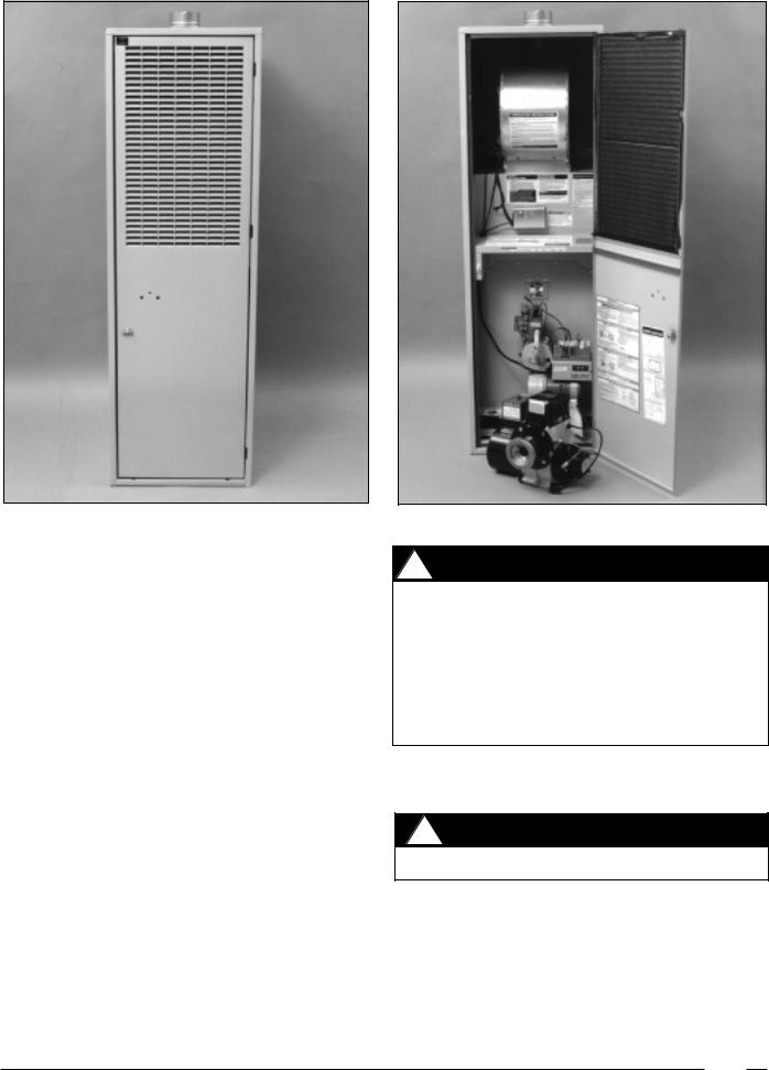
Figure 1
These instructions are intended for use by qualified individuals specially trained and experienced in installation of this type of equipment and related system components. Installation and service personnel are required by some governing bodies to be licensed. Persons not qualified should not attempt to install or service the equipment, nor interpret these instructions. These furnaces must be installed in accordance with local codes and ordinances.
These furnaces are high quality, direct vent furnaces that are convertible from power oil to power gas. The PO models are Power Oil. The PG models are Power Gas models . Gas models are designed for operation with natural or LP. gas.
The furnaces are Listed by Underwriters Inc. for use in manufactured (mobile) homes and recreational vehicles and as a central furnace, special type when installed with model CB200A outlet Air base.
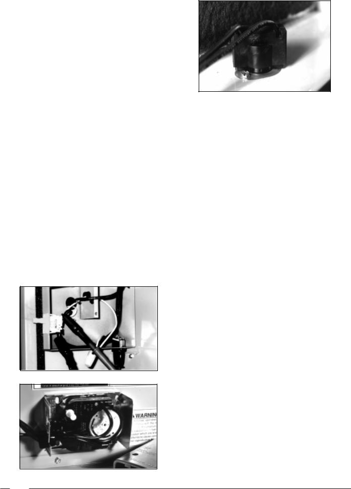
Standard Flue Furnaces
The current line of furnaces using the standard flue system are the CMF series. This is a heating only, sealed combustion furnace, which draws its combustion air from under the home via a combustion air duct and vents the flue gases through the standard roof jack. This furnace must be installed with the MA-100 or MA-200 base, the SRJ series roof jack, and the vent pipe used in conjunction with the SRJ roof jack to meet U.L. requirements.
Figure 2
! WARNING
This furnace must be installed by a qualified installing agency and in accordance with local codes and ordinances. Failure to properly install the furnace, base assembly, and venting system as described in the Installation Instructions may damage the equipment and/or the home, can create a fire or asphyxiation hazard, violates U.S. Listing requirements, and will void the warranty.
Testing the Electrical Polarity (See Figure 3)
1.See line voltage connections on unit wiring diagram in the back of this manual.
! CAUTION
Be careful to avoid electrical shock hazard.
2.With power on at the fuse box, test the line voltage conductors to the ground with a voltmeter set on the proper scale.
a.L1 to ground should read 120 Volt AC ±10%.
b.Neutral to ground should read zero volts.
NOTE: Test with power on and conductors disconnected from furnace connections.
3. If a reading other than above is read, reverse conductors.
3
NOTE: If 120 volts AC + 10% is not read, check power source.
Door Switch (See Figure 3)
The door switch is a safety that will shut off 120 volt power to the furnace when the furnace door is open. It is a 2 position switch.
1.Open furnace door.
2.Attach the voltmeter to the door switch. 120 volt + 10% should be read.
3.Push in on the door switch the reading should go to zero volts.
Remove Door Switch
1.Shut off power to furnace.
2.Disconnect 2 electric wires.
3.Press in at top and bottom of switch.
4.Remove door switch.
5.To reinstall, reverse steps 1 to 4 above.
Fan and Limit Switch Combination
(See Figure 4)
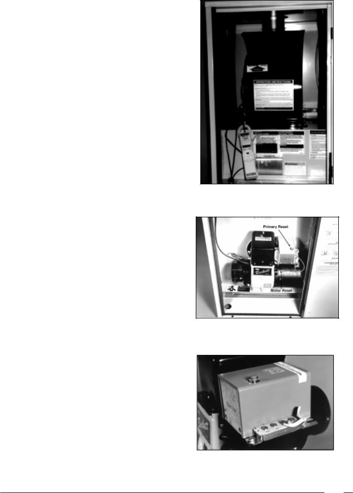
Testing the Limit Switch (See Figure 5)
When testing the limit switch with a voltmeter, a 120V +/- 10% reading indicates the switch is open and defective. The limit switch should be replaced if cooled below switch setting.
1.Turn off electrical power to the main power source.
2.Disconnect wires from limit switch located inside of control panel. See wiring diagram, located in control panel.
Figure 5
3.Using an ohmmeter, connect leads to limit switch terminals.
4.If limit switch is below temperature, it will read continuity. If there is not continuity, replace limit switch by removing two 1/4" screws.
Removing the Limit Switch
1.Turn power off to the unit.
2.Unwire electrical supply.
3.Remove 2, 1/4" screws.
4.To replace, reverse steps 1-3.*
*Limit switch can be either manual or automatic reset. Manual reset limit will be approved on serial date codes of 9706 and later.
Testing the Fan Switch
The steps necessary to check the operation of the fan switch in the air circulation circuit are:
1.Turn off power to unit.
2.Turn voltmeter on and set to scale capable of reading 120V.
3.Place leads from voltmeter on both wires of the fan switch.
4.Turn on 120 volt power supply to furnace. Voltmeter should read 120V ±10%.
5.With voltmeter leads still attached set room thermostat above the room temperature until the burner comes on.
6.Watch the dial on the fan switch as the heat exchanger heats up, the dial should start to rotate. When the fan switch reaches the on temperature setting the blower should come on, and 0 volts should be read indicating a closed switch.
Figure 3
Figure 4
Removing the Fan Switch
1.Shut off power to unit.
2.Remove cover.
3.Disconnect wires.
4.Remove 3, 1/4" screws.
5.To replace, reverse steps 1-4.
Testing Fan Blower Motor
(See Figure 6)
1.Check for 120 Volts + 10%.
2.Check amperage while unit is running.
3.Visually inspect wheel and motor mounting.
4
Removing Blower Motor
1.Turn off power to furnace.
2.Disconnect power wires.
3.Remove two 1/2" screws.
4.Slide blower out.
5.Remove 3, 3/8" screws.
6.Remove blower and blower wheel.
7.Remove blower wheel.
8.To reinstall, reverse steps 1-7.
Testing The Oil Burner
(See Figures 6, 7 and 8)
The two manual resets should be checked before testing any other CMF Furnace Component. These are the Primary Control and the Burner Motor Manual reset.
Check the incoming power with a voltmeter. Set the voltmeter at the proper scale, a 120V ±10% should be obtained. If not, check at power cord:
1.Shut off power to the unit.
2.Remove Electric Panel Cover 1, 5/16" screw.
3.Remove 2 wire nuts.
4.Attach voltmeter to incoming power.
5.Turn on power to the unit.
6.Read voltage 120 +/- 10%.
7.Turn off power and reverse steps 1-3.
Test Oil Pump
The fuel(s) used in the oil gun pressure burner applications are No. 1 Fuel, and No. 2 Fuel . It is recommended to use #1 where temperatures fall below 32°.
The oil storage tank may be installed either above or below grade. Check local or state codes. To prevent abnormal tank pressure during fill, the vent pipe should be 1" to 1 1/4" round. On single line systems, bleed all air out of the fuel supply system before lighting the furnace.
Test fuel pump resistance or vacuum with a vacuum gauge. If vacuum reads greater than 10 inches, look for kinked tubing, a plugged oil filter, undersized line, excessive oil lift, heavy oil or a frozen line.
Maximum Values for Vacuum Hq.
Single Stage - Single Line |
|
(M units) |
6" |
Single Stage - Two Line |
|
(M units) |
10" |
Two Stage |
|
(2 M units) |
15" |
The second fuel pump test is to check the pump efficiency or capacity. With the burner running, the efficiency is satisfactory if the oil pressure can be adjusted to 140 PSI. After checks, adjust the oil pressure for normal operation to 100 PSI.
Figure 6
Figure 7
Figure 8
5
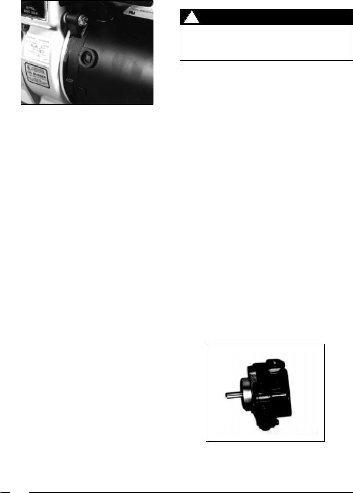
Figure 9
The third fuel pump test is for cut-off. Start the burner and after a few moments of operation shut off the burner. Upon shutdown, pressure should drop approximately 15 to 20 PSI. The two common reasons for inefficient cut-off on fuel pumps are a defective check valve ball in the pump, or poor connectors allowing air into the piping system.
Replacing Oil Pump (See Figure 19, page 8)
1.Shut off and disconnect power to the unit.
2.Shut off oil to pump.
3.Remove oil line.
4.Using a 7/16" wrench, loosen oil lines from pump open to drain assembly.
Conversion from Natural Gas to Propane
! WARNING
Before beginning conversion, shut off electrical power to the furnace at the main power source. Shut off gas supply.
1.Disconnection
a.Low voltage wires
b.Shut off gas to appliance and remove piping to gas valve.
2Remove 3, 3/8" bolts from U-shaped manifold plate and orifice assembly. (See Figure 4, Page 19 )
3.Replace alternate fuel orifice. Using a 1/2" open end wrench, remove the main orifice and replace it with the alternate fuel orifice supplied in the plastic bag with the burner (located with the home owners packet.)
4.Invert the regulator cap. Warning: check for proper orifice size listed on furnace rating plate.
5.To reinstall, reverse steps 1-4. Manifold pressure would then be set to 11.0" W.C. for LP gas.
Changing Complete Burner Assembly
(See Figures 1, page 18 and Figures 2-4, page 19)
1.Open furnace door.
2.Using a 7/16" open end wrench, remove three burner nuts. Remove burner assembly from furnace.
5.Remove oil lines from pump and move out of the way. 3. To replace burner, reverse steps 1 & 2.
6.Remove 1/4" x 20" x 7/8" hex head screws with 3/8"
open end.
7.Pull pump out slowly.
8.To replace, reverse steps 1-7.
When installing single-line systems, the only connections on the burner fuel pump is at the intake port. It is important not to install the “by-pass” plug in the fuel pump return port. A quick rule which can be used for checking an installation with the oil storage tank below the fuel pump is to figure:
1.1" of vacuum for every 10' of horizontal run.
2.1" of vacuum for every 1' of vertical lift.
3.1/2" of vacuum for every 90° elbow fitting.
The single-stage design is used in applications requiring 10" of vacuum or less. Two-stage pumps are specified when up to 15" of vacuum is required. If an oil fuel pump is not properly sized to the vacuum requirements the following will occur:
1.A solid column of oil will not be delivered to the atomizing nozzle.
2.The light portions of the oil will separate from the heavy portion.
3.A milky appearance will be seen in the returned oil.
NOTE: Be certain to install new gasket.
Remove Burner and/or Ignitor
1.Shut off gas supply
2.Remove gas lines from Gas valve.
3.Unplug ignitor.
4.Remove 3, 1/4" screws. Lift burner up and out.
5.Remove 1, 1/4" screw and replace ignitor.
6.Set gap distance between ignitor and burner head at 1/2" - 5/8." Micro amp signal should be between 2 to 4 micro amps (µa).
Figure 10
6

Figure 13
Figure 11
Figure 12
Remove Hot Surface Ignition Series
(See Figure 12)
1.Shut off power to the furnace.
2.Remove all wires 24 volt and 120 volt.
3.Remove 2, 1/4" screws.
4.To remount, reverse steps 1-3.
Removing C Burner Motor (See Figure 4, page 19)
1.Shut off power to the furnace.
2.Remove wires from HSI control.
3.Remove 4, 1/4" screws and HSI control.
4.Remove 2, 1/4" screws and panel cover.
5.Disconnect wires to motor; 2 red and 2 black.
6.Remove 1, 5/8" screw from housing strap and lift off motor.
7.To reinstall, reverse steps 1-6.
Figure 14
Removal of Air Housing, Blower Wheel and Motor (See Figures 14 - 16)
1.Shut off power to unit.
2.Remove elect wires.
3.Remove 4, 1/4" screws (2 on each side of air housing).
4.Remove band screw, 5/16" bolt.
5.To replace, reverse steps 1-4.
The 3 circuits of the primary control (see Figure 14) are the Starting Circuit, Safety Circuit, and the Running Circuit.
Testing the Primary Control Circuits
1.Shut off power to the unit. Close off oil supply.
2.Remove thermostat wires from T1 and T2 and cad cell wires from F1 and F2.
3.Turn on power to the unit.
4.Jumper out terminals T1 and T2 to test the starting circuit. The burner should come on and then shut down after 45 seconds as the safety circuit engages.
Figure 15 |
Figure 16 |
7
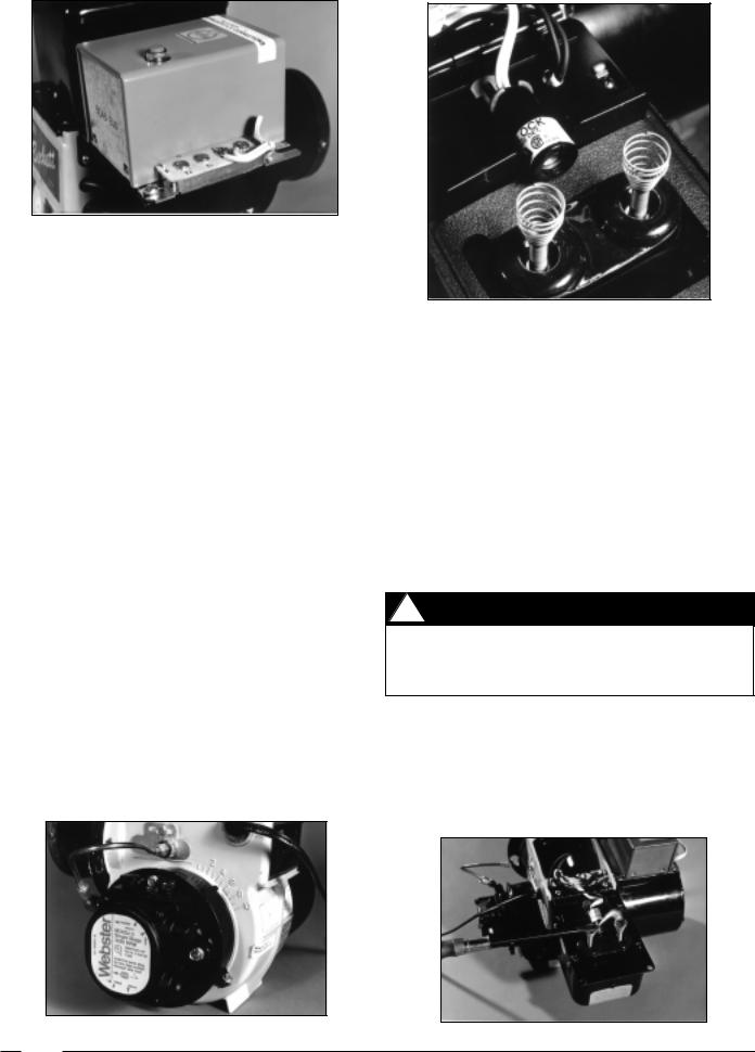
Figure 17
5.Remove jumper wires and allow two minutes for the safety heater to cool off.
6.Test running circuit by jumpering out T1 and T2 and reset the primary control. The burner will come on.
7.Immediately jumper F1 and F2 to bypass the cad cell. The burner should run continuously after 45 seconds with the cad cell safety circuit by-passed.
8.Shut off power to the unit, remove all jumpers, and then reconnect the thermostat and cad cell.
9.If any one of these test fails, replace the primary control.
Removing the Primary Control
1.Shut off power to the unit.
2.Open ignition transformer by removing 2 5/16" screws.
3.Remove the black, white and orange wires leading from the primary control.
4.Remove cad cell wires from F1 and F2, and remove thermostat wires from T1 and T2.
5.Loosen 2, 1/4" screws and remove primary control.
6.To replace, reverse steps 1-5.
Testing Cad Cell
The cad cell is a light sensing resistor. Its function is to cut power to the burner motor in the event the electrodes fail to establish flame.
To check the CAD cell start the burner and unhook both cad cell leads from the FF terminals on the primary control. After the burner lights jump the FF terminals to keep the burner running. Measure the ohms resistance across the cad cell lead as it views the flame. This should be 1,600 ohms or less. A preferred reading is 300-1000 ohms. Next, with the meter still connected to the cad cell leads, turn the burner OFF. The
Figure 18
dark condition should give a reading of 100,000 ohms or infinity. If the reading is lower, let the refractory cool down or look for stray light that might be entering the burner through the air inlet, or around the transformer base plate. If the cad cell is not performing within these guidelines, replace it.
Removing the Cad Cell
(See Figures 17 and 18)
1.Shut off power to the unit.
2.Remove wires from primary control.
3.Open ignition transformer.
4.Turn cad cell 1/2 turn in retainer and lift out.
5.To replace, reverse steps 1-4.
Testing Ignition Transformer (See Figure 20)
! WARNING
In testing the ignition transformer extreme caution should be exercised because 10,000 to 14,000 volts are present.
The most common field test of the ignition transformation spark is using a service test cord connected to the primary winding wiring and an INSULATED screw driver. The tests should indicate an arc:
1. 1/2" long ARC from the terminal post to the casing.
Figure 19 |
Figure 20 |
8
 Loading...