


Downßow, Direct Vent (Sealed Combustion)
Forced Air Gas & Oil Furnaces
Installation Instructions
For installation in:
Series M1B, M1G, M1M & M5S ¥ Manufactured Homes
¥ Recreational Vehicles, Park Models, & Manufactured Buildings
¥ Modular Homes/Buildings
ATTENTION INSTALLERS:
It is your responsibility to know this product better than your customer. This includes being able to install the product according to strict safety guidelines and instructing the customer on how to operate and maintain the equipment for the life of the product. Safety should always be the deciding factor when installing this product and using common sense plays an important role as well. Pay attention to all safety warnings and any other special notes highlighted in the manual. Improper installation of the furnace or failure to follow safety warnings could result in serious injury, death, or property damage.
These instructions are primarily intended to assist qualiÞ ed individuals experienced in the proper installation of this appliance. Some local codes require licensed installation/service personnel for this type of equipment. Please read all instructions carefully before starting the installation. Return these instructions to the customerÕs package for future reference.
! WARNING:
WHAT TO DO IF YOU SMELL GAS
¥Do not try to light any appliance.
¥Do not touch any electrical switch; do not use any phone in your building.
¥Leave the building immediately.
¥Immediately call your gas supplier from a neighbors phone. Follow the gas suppliers instructions.
¥If you cannot reach your gas supplier, call the Þre department
FIRE OR EXPLOSION HAZARD
¥Failure to follow safety warnings exactly could result in serious injury or property damage.
¥Installation and service must be performed by a qualified installer, service agency or the gas supplier.
¥Do not store or use gasoline or other ßammable vapors and liquids in the vicinity of this or any other appliance.
DO NOT DESTROY. PLEASE READ CAREFULLY AND KEEP IN A SAFE PLACE FOR FUTURE REFERENCE.

SAFETY INFORMATION .............................. |
3 |
REQUIREMENTS & CODES ........................ |
3 |
GENERAL INFORMATION........................... |
5 |
Warranty Information ................................ |
5 |
Minimum Clearances ............................... |
5 |
Applications ............................................. |
6 |
Unit Location ............................................ |
6 |
CIRCULATING AIR REQUIREMENTS ......... |
7 |
Return Air Connections ........................... |
7 |
Supply Air Connections ............................ |
7 |
FURNACE INSTALLATION .......................... |
8 |
General Information.................................. |
8 |
Requirements & Codes ............................ |
8 |
Locating & Cutting Duct Openings .......... |
8 |
Standard Duct Connector Installation....... |
9 |
Alternate Attachment Method ............... |
10 |
Round Duct Connector Installation.......... |
10 |
Installing the Furnace .............................. |
10 |
ROOF JACK INSTALLATION...................... |
11 |
Roof Jack Selection................................. |
11 |
Application Notes..................................... |
11 |
Locating & Cutting Roof Openings .......... |
12 |
Installing the Roof Jack............................ |
13 |
Installation of Transit-Mode Vent System.13 |
|
Manufactured Home Factory................. |
13 |
ELECTRICAL INFORMATION..................... |
14 |
Line Voltage Wiring .................................. |
14 |
Connecting Power Supply Wires........... |
15 |
Low Voltage Wiring .................................. |
15 |
Connecting Thermostat Wires............... |
15 |
Verifying Anticipator Setting.................. |
15 |
Grounding................................................ |
15 |
FUEL SUPPLY AND PIPING ....................... |
16 |
Oil Tank & Piping Istallation ..................... |
17 |
One Line System .................................. |
17 |
Two Line System................................... |
17 |
Fuel Line Hook Up .................................. |
17 |
Leak Check ............................................. |
18 |
Priming Honeywell R7184 ...................... |
18 |
Priming Beckett 7505 .............................. |
18 |
Fuel Oil Type ........................................... |
18 |
Conversion to Propane Gas ................... |
18 |
Atmospheric & Direct Ignition .............. |
18 |
High Altitude Conversion ........................ |
19 |
Flue Gas Sampling ................................. |
19 |
STARTUP & ADJUSTMENTS ..................... |
20 |
Lighting Instructions - Pilot Models.......... |
20 |
How to Shut Off Gas - Pilot Models...... |
21 |
Operating Instructions - Direct Ignition ... |
21 |
How to Shut Off Gas - Direct Ignition ... |
22 |
Operating Instructions - Oil Gun .............. |
22 |
Operating Instructions - Gas Gun............ |
22 |
How to Shut Off Gas - Gas Gun........... |
22 |
Burner Adjustments................................. |
22 |
Gas Pressure ....................................... |
22 |
Pilot Flame ........................................... |
22 |
Combustion Air ........................................ |
23 |
Gas Gun ............................................... |
23 |
Oil Gun ................................................. |
23 |
Electrode Setting - Oil Gun...................... |
23 |
Switching Honeywell (R7184) Ignition from |
|
Interrupted to Intermittent ........................ |
23 |
OPERATING SEQUENCE ........................... |
24 |
Standing Pilot .......................................... |
24 |
Standing Pilot w/ Induced Draft Blower ... |
24 |
M1 Models - Direct Ignition...................... |
24 |
Oil Gun Models........................................ |
24 |
Gas Gun Models...................................... |
24 |
FURNACE CONTROLS & FUNCTIONS ..... |
25 |
Furnace On-Off Switch............................ |
25 |
Limit Control ............................................ |
25 |
Gas Valve................................................. |
25 |
Roll Out Switch - M1G ............................. |
25 |
Oil Burner Primary Control ...................... |
25 |
Summer Cooling - B,C,D Series.............. |
25 |
TROUBLESHOOTING ................................. |
26 |
Standing Pilot Models.............................. |
26 |
Direct Ignition Models .............................. |
26 |
Oil Gun Models........................................ |
27 |
OPTIONAL ACCESSORIES........................ |
28 |
MAINTENANCE ........................................... |
30 |
Homeowner Information .......................... |
30 |
Installer Information Information .............. |
30 |
FIGURE & TABLES...................................... |
31 |
Table 10 - Furnace SpeciÞ cations ........ |
31 |
Table 11 - OriÞ ce Sizes - High Alt......... |
32 |
Table 12 - Blower Speed Selection....... |
32 |
Gas Information ....................................... |
33 |
Table 13 - Gas Flow Rates ................... |
33 |
Table 14 - Gas Pipe Capacities ............ |
33 |
Wiring Diagrams ...................................... |
34 |
Fig. 39 - Gas Furnace - 056, 070 ......... |
34 |
Fig. 41 - Standing Pilot - 077, 090 ........ |
35 |
Fig. 42 - Gas Furn. w/ac 056, 070 ........ |
36 |
Fig. 43 - Standing Pilot. w/ac 077, 090 .37 |
|
Fig. 44 - Gas Only (M1M Models) ........ |
38 |
Fig. 45 - Gas & Oil (M1B & M5S) ......... |
39 |
Installation Checklist................................ |
40 |
2

SAFETY INFORMATION
Safety markings are used frequently throughout this manual to designate a degree or level of seriousness and should not be ignored. WARNING indicates a potentially hazardous situation that if not avoided, could result in personal injury or death. CAUTION indicates a potentially hazardous situation that if not avoided, may result in minor or moderate injury or property damage.
 WARNING:
The safety information listed below must be followed during the installation,service,and operation of this furnace. Failure to follow safety recommendations could result in possible damage to the equipment,serious personal injury or death.
¥Use only with type of gas approved for this furnace. Refer to the furnace rating plate.
¥Install this furnace in accordance to the minimum clearances to combustible materials listed in Table 1 (page 5).
¥Provideadequate combustion airtothe furnace space as speciÞ ed on page 23.
¥Combustion products must be discharged outdoors.Connect this furnace to an approved vent system, as speciÞ ed on pages 13 - 14.
¥Never test for gas leaks with an open ß ame. Use a commercially available soap solution to check all connections (page 18).
¥This furnace is designed to operate with a maximum external pressure rise of 0.5 inches of water column. Consult Table 8 (page 38), and the rating plate for the proper circulating air ß ow and temperature rise.
NOTE: It is important that the duct system be designed to handle the desired ß ow rate and external pressure rise.An improperly designed duct system can result in nuisance shutdowns, and comfort or noise issues.
¥This furnace may not be used for temporary heating of buildings or structures under construction.
¥When supply ducts carry air circulated by the furnace to areas outside the space containing the furnace, the return air shall also be handled by duct(s) sealed to the furnace casing and terminating outside the space containing the furnace. See page 14.
 WARNING:
Do not use this appliance if any part has been submerged under water. Immediately call a qualiÞed service technician to inspect the appliance and to replace any part of the control system and any gas control that has been submerged underwater.
Notice to Installer
Installer is advised to carefully follow all instructions and warnings in this manual to insure maximum performance, safety, and operating efficiency of these appliances. Improper installation may create hazardous conditions, and will void the appliance warranty.
 WARNING:
PROPOSITION 65 WARNING: This product contains chemicals known to the state of California to cause cancer, birth defects or other reproductive harm.
REQUIREMENTS AND CODES
This furnace must be installed in accordance with these instructions, all applicable local building codes and the current revision of the National Fuel Gas Code (NFPA54/ANSI Z223.1) or the Natural Gas and Propane Installation Code, CAN/CGA B149.1.
CE gŽnŽrateur dÕair chaud doit •tre installŽ conformŽment aux instructions du fabricant et aux codes locaux. En lÕabsence de code local, respecter la norme ANSI Z223.,1, institulŽ National Fuel Gas Code ou les codes dÕinstallation CAN/GCA-B149.
The Commonwealth of Massachusetts requires compliance with regulation 248 CMR 4.00 and 5.00 for installation of through Ð the Ð wall vented gas appliances as follows:
1.For direct-vent appliances, mechanicalvent heating appliances or domestic hot water equipment, where the bottom of the vent terminal and the air intake is installed below four feet above grade the following requirements must be satisÞ ed:
3

a.) A carbon monoxide (CO) detector and alarm shall be placed on each ß oor level where there are bedrooms. The detector shall comply with NFPA 720 (2005 Edition) and be mounted in the living area outside the bedroom(s).
b.) A (CO) detector shall be located in the room that houses the appliance or equipment and shall:
¥Be powered by the same electrical circuit as the appliance or equipment. Only one service switch shall power the appliance and the (CO) detector;
¥Have battery back-up power;
¥Meet ANSI/UL 2034 Standards and comply with NFPA 720 (2005 Edition); and Approved and listed
|
by a Nationally Recognized Testing |
|
Laboratory as recognized under 527 |
|
CMR. |
c.) |
A Product-approved vent terminal must |
|
be used, and if applicable, a product- |
|
approved air intake must be used. |
|
Installation shall be in strict compliance |
|
with the manufacturerÕs instructions. A |
|
copy of the installation instructions shall |
|
remain with the appliance or equipment |
|
at the completion of the installation. |
d.) |
A metal or plastic identiÞcation plate shall |
|
be mounted at the exterior of the building, |
|
4 feet directly above the location of vent |
|
terminal. The plate shall be of sufÞ cient |
|
size, easily read from a distance of eight |
|
feet away, and read ÒGas Vent Directly |
|
BelowÓ. |
2.For direct-vent appliances, mechanical vent heating appliances or domestic hot water equipment where the bottom of the
vent terminal and the air intake is installed above four feet above grade the following requirements must be satisÞ ed:
a.) |
A (CO) detector and alarm shall be |
|
placed on each ß oor level where there |
|
are bedrooms.The detector shall comply |
|
with NFPA 720 (2005 Edition) and be |
|
mounted in the living area outside the |
|
bedroom(s). |
b.) |
The (CO) detector shall: |
¥Be located in the room that houses the appliance or equipment;
¥Behard-wired,batterypoweredorboth.
¥Shall comply with NFPA 720 (2005 Edition).
c.) A product-approved vent terminal must be used, and if applicable, a productapproved air intake must be used. Installation shall be in strict compliance with the manufacturerÕs instructions. A
copy of the installation instructions shall remain with the appliance or equipment at the completion of the installation.
The information listed below is for reference purposes only and does not necessarily have jurisdiction over local or state codes. Always consult with local authorities before installing any gas appliance.
Combustion and Ventilation Air
¥US: National Fuel Gas Code (NFGC), Air for Combustion and Ventilation
¥CANADA: Natural Gas and Propane Installation Codes (NSCNGPIC), Venting Systems and Air Supply for Appliances
Duct Systems
¥US and CANADA:Air Conditioning Contractors Association (ACCA) Manual D, Sheet Metal and Air Conditioning Contractors National Association (SMACNA), or American Society of Heating, Refrigeration, and Air Conditioning Engineers (ASHRAE) Fundamentals Handbook
Electrical Connections
¥US: National Electrical Code (NEC) ANSI/ NFPA 70
¥CANADA: Canadian Electrical Code CSA C22.1
Gas Piping and Gas Pipe Pressure Testing
¥US: NFGC and National Plumbing Codes
¥CANADA: NSCNGPIC
General Installation
¥US: Current edition of the NFGC and the NFPA 90B. For copies, contact the National Fire Protection Association Inc., Batterymarch Park, Quincy, MA 02269; or American Gas Association, 400 N.Capitol, N.W.,Washington DC 20001 or www.NFPA.org
¥CANADA: NSCNGPIC. For a copy, contact Standard Sales, CSA International, 178 Rexdale Boulevard, Etobicoke (Toronto), Ontario, M9W 1R3 Canada
Safety
¥US:(NFGC) NFPA 54Ð1999/ANSI Z223.1 and the Installation Standards, Warm Air Heating and Air Conditioning Systems ANSI/NFPA 90B.
¥Federal Manufactured Home Constructions & Safety Standard (H.U.D. Title 24, Part 3280.707[a][2])
¥The Standard for Manufactured Home Installations (Manufactured Home Sites, Communities, and Set-Ups) ANSI A225.1 and/ or CAN/CSA-2240 MH Series).
4

¥American National Standard (ANSI-119.2/ NFPA-501C) for all recreational vehicle installations.
¥CANADA: CAN/CGA-B149.1 and .2ÐM00 National Standard of Canada. (NSCNGPIC)
GENERAL INFORMATION
M a n u f a c t u r e r Wa r r a n t y - O w n e r Õs Responsibilities
It is the sole responsibility of the homeowner to make certain the gas furnace has been correctly set up and converted to the proper fuel (L.P. gas or Natural gas) and adjusted to operate properly. All gas furnaces are manufactured for Natural gas and must be Þ eld converted when using L.P.gas.
 CAUTION:
¥Do Not alter or modify this furnace or any of its components.
¥Never attempt to repair damaged or inoperable components. This may cause unsafe operation, explosion, Þre and/or asphyxiation.
¥If furnace malfunctions or does not operate properly, contact a qualiÞed service agency or gas utility for assistance.
A warranty certiÞ cate with full details is included with these instructions. However, NORDYNE will not be responsible for any costs found necessary to correct problems due to improper setup,improperinstallation,furnaceadjustments, improper operating procedure on the part of the user, etc. Carefully review these responsibilities with your manufactured housing dealer, service companyorgassupplier.SomespeciÞcexamples of service calls which cannot be included in warranty payments are:
¥Converting the furnace to use another type of gas.
¥Repairing duct work in the home found to be faulty.
¥Correcting wiring problems in the electrical circuit supplying the furnace.
¥Resetting circuit breakers, blown fuses or other switches.
¥Correcting problems due to improper gas supply pressure to the furnace.
¥Providing instructional training on how to light and operate the furnace.
¥Furnace problems caused by installation of an air conditioner, heat pump or other air comfort devices.
¥Adding a Roof Jack extension because of unusual wind and/or snow conditions.
¥Revising installation of the furnace flue assembly (Roof Jack).
¥Adjusting or calibrating of thermostat.
¥Any construction debris which falls into ß ue system.
Minimum Clearances
This heating appliance must be installed with clearances not less than the minimums listed in Table 1. This furnace must be installed with ample clearance for easy access to the air Þ lter, blower assembly, burner assembly, controls, and vent connections. See Figures 1 - 3 (page 6).
¥The dimensions of the room or alcove must be able to accommodate the overall size of the furnace and the installation clearances listed in Table 1 and in Figure 4 (page 6).
¥Alcove installations: minimum 18Ó clearance at front of furnace shall be provided for future servicing. A removable access panel should be installed between top of the furnace door frame and the ceiling.
¥Closet installations must use a louvered door having a minimum free area of 235 sq.in.when located 6Ó from furnace or 390 sq. in. for 5 ton ready M1/M5 furnaces. For special clearance between 1Óand 6Ó, requirements are a louvered door with a minimum of 250 sq. in. free area, with the openings in the closet door in line with the louvered openings in the furnace door. A fully louvered closet door may be used. See Circulating Air Requirements (page 7).
ALL MODELS |
CLOSET |
ALCOVE |
|
|
|
|
|
Front |
6Ó |
|
18Ó |
|
|
|
|
Back |
0Ó |
|
0Ó |
Sides |
0Ó |
|
0Ó |
Roof Jack |
0Ó |
|
0Ó |
Top |
6Ó |
|
6Ó |
|
|
|
|
Top and Sides of Duct |
0Ó |
|
0Ó |
|
|
|
|
Bottom of Duct |
|
|
|
B Cabinet |
0Ó |
|
0Ó |
A Cabinet |
0Ó |
|
0Ó |
(w/ coil box) |
|
||
|
|
|
|
|
|
|
|
A Cabinet |
1/4Ó |
|
1/4Ó |
(w/o coil box) |
|
||
|
|
|
|
|
|
|
|
Table 1. Minimum Clearances |
|
||
5

6" (152 mm) Top Clearance
|
Removable access |
|
0" Side |
panel should be |
|
installed above |
||
Clearance |
||
furnace door frame |
||
to Furnace |
||
to access roof jack |
||
Cabinet |
||
|
18" |
|
|
(457 |
mm) |
Nearest |
|
|
Wall or |
|
|
Partition |
Figure 1. Alcove Installation
6" (152 mm) Top Clearance
0" Side  Clearance to Furnace Cabinet
Provide min. 235 sq. in. (1516 cm2 )
open free area in
front or side wall
or
In closet door
located at top, center
or bottom
(152 |
6" |
|
mm) |
||
|
CLOSET DOOR
Figure 2. Closet Installation
6" (152 mm) Top Clearance
0" Side  Clearance to Furnace Cabinet
Provide min. 250 sq. in. (1613 cm 2) open free area in front or side wall
or
in closet door
a fully louvered door may be used
(25 |
1" |
|
mm) |
||
|
CLOSET DOOR
Figure 3. Special 1Ó Clearance
|
Blower / Motor |
|
|
Part |
Assembly |
A/C Capacity |
|
No. |
Blower |
Motor |
(Tons) |
|
Wheel |
(Hp) |
|
903773 |
10 x 8 |
1/4 |
2, 2½ & 3 |
903413 |
11 x 8 |
1/2 |
2, 2½, 3 & 4 |
903890 |
11 x 8 |
3/4 |
2, 2½, 3, 4 & 5 |
Table 2. Blower Assemblies
Applications
M1 Series gas and M5 Series oil furnaces are listed direct vent (sealed combustion), downß ow heating appliances for manufactured (mobile) homes, recreational vehicles, and for use in residential/modular/commercial construction. The furnace must be located so that venting can be properly achieved.
Air conditioning may be added to structures with M1/M5 series furnaces using air conditioning or conventional units. This Installation Instruction manual includes special requirements for incorporation of air conditioning equipment to the M1/M5seriesoffurnaces.SeeTabel12(page32).
Multi-speed blower assemblies shown in Table 2, have been certiÞ ed for Þ eld installation in M1/ M5 Series furnaces.
Unit Location
¥The furnace shall be appropriately located to the supply and return air distribution system (See Page 7). Sides and back of the furnace may be enclosed by wall framing.See Minimum Clearances (page 2) and Figures 1- 3.
¥The furnace installation is only intended for free air return through the furnace door louvers. DO NOT connect a ducted return air system directly to the furnace. Improper installation may create a hazard and damage equipment, as well as void all warranties.
¥Furnace may be installed on combustible flooring when using NORDYNE Duct Connectors. See pages 9 & 10.
¥When installed in a residential garage, the furnace must be positioned so the burners and the source of the ignition are located no less than 18 inches above the ß oor and protected from physical damage by vehicles.
ÒAÓ56" |
|
ÒAÓ Model |
|
w/o Coil |
ÒBÓ76" |
Cabinet |
|
ÒBÓ Model |
|
w/Coil |
|
Cabinet |
|
23 3/4"
 19 3/4"

Figure 4. Overall Dimensions
6

CIRCULATING AIR REQUIREMENTS
 WARNING:
Do not allow combustion products to enter the circulating air supply. Failure to prevent the circulation of combustion products into the living space can create potentially hazardous conditions including carbon monoxide poisoning that could result in personal injury or death.
All return ductwork must be secured to the furnace with sheet metal screws. For installations in conÞned spaces, allreturnductworkmustbeadequately sealed.The joint between the furnace and the return air plenum must be air tight.
The surface that the furnace is mounted on must provide sound physical support of the furnace with no gaps, cracks or sagging between the furnace and the ßoor or platform.
Return air and circulating air ductwork must not be connected to any other heat producing device such as a fireplace insert, stove, etc. This may result in Þre, explosion, carbon monoxide poisoning, personal injury, or property damage.
Return Air Connections
U.S.A. home manufacturers shall comply with all of the following conditions to have acceptable return air systems for closet installed forced air heating appliances:
¥The return air opening into the closet shall not be less than speciÞ ed in the applianceÕs listing.
¥The cross-sectional area of the return duct system leading into the closet, when located in the ß oor or ceiling shall not be less than 235 square inches (or 390 square inches for 5 ton ready M1/M5 Furnaces).
 CAUTION:
HAZARD OF ASPHYXIATION: Do not cover or restrict return air opening.
¥Means shall be provided that prevent inadvertent closure of ß at objects placed over the return air opening located in the ß oor of the closet (versus the vertical front or side wall).
¥The total free area of openings in the ß oor or ceiling registers serving the return air duct system must be at least 235 sq. in. At least one register should be located where it is not likely to be covered by carpeting, boxes and other objects.
¥Materials located in the return duct system must have a ß ame spread classiÞ cation of 200 or less. This includes a closet door if the furnace is in a closet.
¥Noncombustible pans having 1Ó upturned
ßanges are located beneath openings in a
ßoor duct system.
¥Wiring materials located in the return duct system shall conform to Articles 300-22 of the National Electrical Code (ANSI C1/NFPA-70).
¥Gas piping is not run in or through the return duct system.
 CAUTION:
HAZARD OF ASPHYXIATION: Negative pressure inside the closet, with closet door closed and the furnace blower operating on high speed, shall be no more negative than minus 0.05 inch water column.
¥Test the negative pressure in the closet with the air-circulating fan operating at high speed and the closet closed.The negative pressure is to be no more negative than minus 0.05 inch water column.
¥Air conditioning systems may require more duct register and open louver area to obtain necessary airflow. Use NORDYNEÕs certiduct program to determine proper duct size for A/C.
Supply Air Connections
For proper air distribution, the supply duct system must be designed so that the static pressure measured external to the furnace does not exceed the listed static pressure rating shown on the furnace rating plate.
7
Location, size, and number of registers should be selected on the basis of best air distribution and ß oor plan of the home. The supply air must be delivered to the heated space by duct(s) secured to the furnace casing, running full size and without interruption.
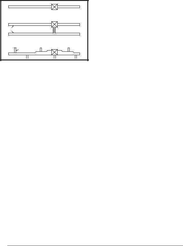
Three typical distribution systems are shown in Figure 5. The location, size, and number of registers should be selected on the basis of best air distribution and ß oor plan of the home.
A Single trunk duct |
|
B |
Dual trunk duct |
w/crossover connector |
|
|
Transition duct |
C |
w/branches |
|
|
Figure 5. Typical Supply Duct System
FURNACE INSTALLATION
NOTE: These Installation procedures are suggested for typical furnace installations. Since all installations are different from each other, the sequence of instructions may differ from the actual installation. Only qualiÞ ed HVAC technicians should install this furnace.
General Information
¥The furnace must be leveled at installation and attached to a properly installed duct system.Do not use the back of the furnace for return air. See page 7 for circulating requirements.
¥The furnace must be installed so that all electrical components are protected from water.
¥The dimensions of the room or alcove must be able to accommodate the overall size of the furnace and the installation clearances listed in Table 1 and Figure 3 (page 6)
¥The furnace must be installed upstream from a refrigeration system.
¥The plenum attached to the A/C coil box and ductwork within 3 ft. of the furnace must be installed so that surfaces are at least 1/4Ó from combustible construction.
¥The cabinet plug must always be used to close the hole in the side of the furnace when rotating the inducer.
¥M1/M5 models must be installed with the Nordyne A/C coil box which are listed according to the cabinet size of the furnace: ÒBÓ cabinet - 920169, ÒCÓcabinet - 920171, andÒDÓcabinet - 920172.
¥The M1 Series gas and M5 Series oil furnace is certiÞed for use on wood ßooring or supports, but must be installed on top of a duct connector. This factory supplied accessory must be installed in the ß oor cavity and attached to the supply air duct before the furnace is installed.
Requirements and Codes
Installer must be familiar with and comply with all codes and regulations applicable to the installation of these heating appliances and related equipment.In the absence of local codes, the installation must be in accordance with the current provisions of one or more of the following standards.
¥Federal Manufactured Home Constructions & Safety Standard (H.U.D. Title 24, Part 3280.707[a][2])
¥American National Standard (ANSI-119.2/ NFPA-501C) for all recreational vehicle installations.
¥American National Standard (ANSI-Z223.1/ NFPA-54) and/or CAN/CSA B149 for all gas- Þ red furnace models.
¥American National Standard (ANSI-Z95.1/ NFPA-31) and/or CSA B139 for all oil-Þ red furnace models.
¥American National Standard (ANSI-C1/NFPA- 70) and/or CSA 22.1 Canadian Electric Code Part 1 for all electrical Þ eld wiring.
¥Units have been researched under standards UL 307A & B, UL727-1999, ANSI Z21.47b/ CSA 2.3b-2008, and CSA B140.10.
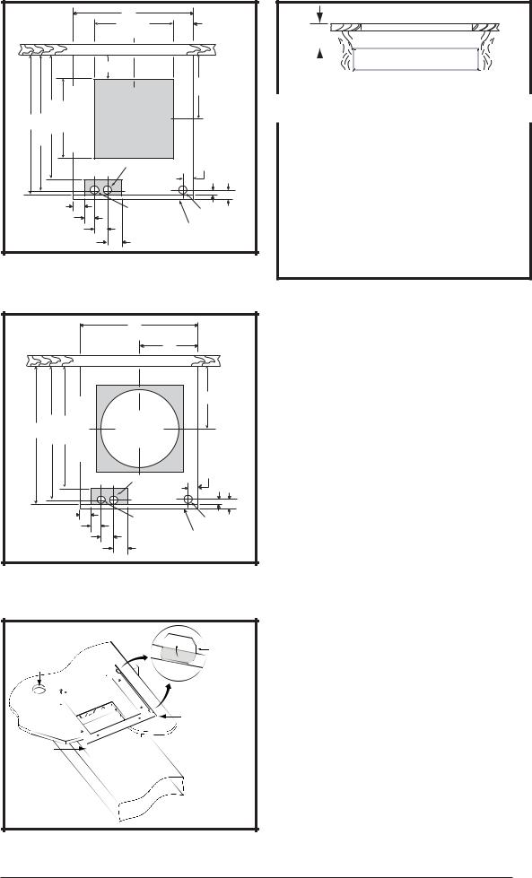
Locating and Cutting Duct Openings
Floor cut-outs and fuel line holes must be carefully located to avoid misalignment of the furnace, and vent piping. To locate standard ducts see Figure 6 (page 9). For round ducts, see Figure 7.
1.Measure 10Ó from the rear wall or alcove and mark the centerline of the cut-out on the ß oor.
2.Using the centerline as a starting point, draw the rest of the duct cut-out to the dimensions shown in Figures 6 or 7.
3.Cut out the ß oor opening 1/16Ó larger than the actual cutout drawn. This will allow some clearance when installing the duct connector.
4.Measure from the top of the ß oor down to the top of the supply air duct to obtain the depth of the ß oor cavity. NOTE: The depth of the ß oor cavity shown as ÒXÓ in Figure 9 (page 9) will determine the correct duct connector.
5.Determine which duct connector to use from Table 3 (page 9).
6.Measure and drill gas hole. and cut out for cooling coil (if applicable). See Figures 6 or 7 (page 9).
8
|
|
|
|
|
20" |
|
|
|
|
|
|
|
|
14 1/2" |
|
2 3/4" |
|
|
|
|
|
|
C |
|
|
|
|
|
|
|
|
L |
|
|
|
|
|
|
REAR WALL OF CLOSET OR ALCOVE |
|
|
|||
|
|
|
2 1/4" |
|
|
|
||
|
|
|
|
FLOOR CUT-OUT |
|
C |
|
|
|
|
|
|
FOR STANDARD |
|
|
||
|
|
|
|
|
L |
|
||
|
231/4" 3/4"21 |
1/2"14 |
DUCT CONNECTORS |
|
10" |
|
||
24" |
OUTLINEFURNACE |
|
|
|
|
|||
|
|
|
C |
C |
CUT-OUT FOR |
C |
1 3/4" |
|
|
|
|
OPTIONAL |
L |
|
|
||
|
|
|
L |
L |
COOLING COIL |
|
3/4" |
|
|
|
|
|
|
|
|
||
C |
|
|
|
|
|
|
|
C |
L |
|
|
|
|
|
|
|
L |
|
1 3/4" |
|
|
ALT FUEL-LINE |
|
FUEL |
2" |
|
|
|
3/4" |
|
ENTRY 1 1/4" Dia. |
||||
|
|
|
LINE |
|
||||
|
|
|
|
|
|
|||
|
|
1 7/8" |
|
|
FURNACE |
|
||
|
|
|
|
|
|
OUTER |
|
|
|
|
|
2 7/8" |
|
|
DOOR |
|
|
|
|
|
|
|
|
|
|
|
Figure 6. Cut-Out Dimensions for Standard Duct Connectors
|
|
|
|
|
20" |
|
|
|
|
|
|
|
C |
|
|
|
|
|
|
|
L |
|
|
|
|
|
|
|
10" |
|
|
|
|
|
REAR WALL OF CLOSET OR ALCOVE |
|
|||
|
|
|
|
|
FLOOR |
|
|
|
|
|
|
|
CUT-OUT FOR |
C |
|
|
|
|
|
|
ROUND DUCT |
L |
|
24" |
1/4"23 |
3/4"21 |
FURNACEOUTLINE |
|
10" |
|
|
(14 1/4Ó DIAMETER) |
|
||||||
|
|
|
|||||
|
|
|
|
|
|
1 3/4" |
|
|
|
|
C |
C |
CUT-OUT FOR |
C |
|
|
|
|
L |
|
|||
|
|
|
L |
L |
OPTIONAL |
3/4" |
|
|
|
|
|
|
|||
|
|
|
|
|
COOLING COIL |
|
|
|
C |
|
|
|
C |
|
|
|
L |
|
|
|
L |
|
|
|
1 3/4" |
|
ALT FUEL-LINE |
FUEL |
2" |
||
|
|
3/4" |
|
||||
|
|
|
ENTRY 1 1/4" Dia. |
LINE |
|
||
|
|
|
1 7/8" |
|
FURNACE |
|
|
|
|
|
2 7/8" |
|
|
OUTER |
|
|
|
|
|
|
DOOR |
|
|
Figure 7. Cut-Out Dimensions for Round Duct Connectors
Hole for |
Floor |
|
Bend tabs |
|
up 90¡ |
||
Gas Line |
Wood |
|
|
|
Connector |
|
|
|
Tabs |
|
|
|
|
|
Mounting Plate |
Duct |
|
|
|
Connector |
|
Supply |
|
|
|
||
|
|
Air |
Duct |
|
|
|
|
Figure 8. Standard Duct Connector In-
stalled
FLOOR OPENING
|
ÒXÓ |
|
|
|
|
|
|
|
||
|
|
|
|
|
|
|
|
|
||
|
|
|
|
|
SUPPLY AIR DUCT |
|
|
|
||
|
|
|
|
|
|
|
|
|||
FLOOR |
|
|
|
|
|
|
|
|||
|
|
|
|
|
|
|
||||
|
|
|
|
|
|
|
||||
CAVITY |
|
|
|
|
|
|||||
|
|
|
|
|
|
|
|
|||
|
|
|
Figure 9. Floor Cavity |
|
|
|
||||
|
|
|
|
|
|
|
|
|
||
If Floor Cavity |
Duct Connector |
|||||||||
Type & Part Number |
||||||||||
|
ÒXÓ is: |
|||||||||
|
Standard Duct |
|
Round Duct |
|||||||
|
|
|
|
|
|
|||||
7/8Ó / (22) |
|
901987A |
|
904008 |
||||||
2Ó / (51) |
|
901988A |
|
904009 |
||||||
4-1/4Ó / (108) |
901989A |
|
904010 |
|||||||
6-1/4Ó / (159) |
901990A |
|
904011 |
|||||||
8-1/4Ó / (210) |
901991A |
|
904012 |
|||||||
10-1/4Ó / (260) |
901992A |
|
904013 |
|||||||
12-1/4Ó / (311) |
901993A |
|
904014 |
|||||||
Note: Dimensions shown as Inches / (Millimeter)
Table 3. Duct Connector Sizes
Standard Duct Connector Installation
The standard duct connector is designed for use on ducts 12Ó in width. However ducts narrower than 12Ó may not allow sufÞ cient clearances for this type of installation. For an alternate installation method, see page 10.
1.Center the duct connector in the ß oor opening with bottom tabs resting on top of the supply air duct.
2.Mark the cut-out area on the supply air duct by tracing around the connector tabs (Figure 8) of the duct connector.
3.Remove the duct connector and cut out the marked area of the supply air duct 1/4Ó larger the actual cutout drawn.
4.Install the duct connector back in the ß oor opening with the bottom tabs extending into the supply air duct.
5.Install the mounting plate (Figure 8) under the back side of the duct connector. Align the screw holes in both components.
6.Secure the duct connector and the mounting plate to the wood ß oor with appropriate size screws.
7.Bend the connector tabs on the bottom of the duct connector upwards and as tight as possible against the supply air duct.
8.Bend both tabs on the mounting plate up 90¡. See Figure 10, (page 10)
9.Seal all connections with industrial grade sealing tape or liquid sealant.
NOTE: Requirements for sealing ductwork vary from region to region. Consult with local codes for requirements speciÞ c to your area.
9
DUCT CONNECTOR
SUPPLY |
AIR DUCT |
BEND TABS TIGHTLY |
AGAINST SUPPLY AIR DUCT |
Figure 10. Duct Connector Tabs
Alternate Attachment Method
The standard duct connector is designed for use on ducts 12Ó in width. However if there is insufÞ cient clearance to bend the duct connector tabs, this alternate attachment method may be used.
1.Score and cut the top of the supply air duct as indicated in Option 1 or Option 2 (Figure 11). With Option 1 choice, cut out the metal from the shaded area.
2.Fold the two ß aps (Options 1 or 2) up to form the opening for the duct connector.
3.Install the duct connector with the bottom tabs extending into the supply air duct.
4.Bend the tabs on the bottom of the duct connector upwards and as tight as possible against the supply air duct (Figure 12).
5.Form the ß aps (Options 1 or 2) up against the duct connector as tight as possible.
6.Securetheductconnectorßapstothesupplyair duct with staples (3 minimum) or if a 2x block/ joist is not provided, use sheet metal screws (2 minimum). NOTE: The duct connector tabs may be attached to the air duct with sheet metal screws or other suitable fasteners as long as the duct connector and the air duct are securely attached.
7.Seal all connections with industrial grade sealing tape or liquid sealant.
NOTE: Requirements for sealing ductwork vary from region to region. Consult with local codes for requirements speciÞ c to your area.
|
|
|
OPTION 1 |
|
|
|
|
|
|
|
|
OPTION 2 |
|
|
||||||
|
|
|
|
|
|
Remove |
|
|
|
|
|
|
|
|
|
|
|
|
|
|
|
|
|
|
|
|
this |
|
|
|
|
|
|
|
|
|
|
|
|
|
|
|
|
|
|
|
|
Flap |
|
|
|
Supply |
|
|
|
|
Cut Here |
|
|
|||
|
|
|
Cut Here |
|
|
|
|
|
|
|
|
|
||||||||
|
|
|
Here |
|
|
|
Air Duct |
|
|
|
||||||||||
|
|
|
Cut |
|
|
|
|
|
|
|
|
|
|
|
|
|||||
|
|
|
|
|
|
|
|
|
|
|
|
|
|
|
|
|
|
|
||
|
|
|
Here |
Cut |
|
|
|
|
|
|
|
|
|
Here |
|
|
|
|
||
|
|
|
|
|
|
|
|
|
|
|
|
|
|
|
|
|||||
HereFlapFold |
|
Here |
|
|
HereFlapFold |
|
|
|
|
|
Cut |
|
|
HereFlapFold |
||||||
Cut |
Cut |
|
|
HereFlapFold |
|
|
|
|||||||||||||
|
|
|
|
|
|
|
|
|
|
|
|
|
|
|
|
|||||
|
|
|
|
|
Here |
|
|
|
|
|
|
|
|
|
|
|
|
|
||
|
|
|
|
|
|
|
|
|
|
|
|
|
|
|
|
|
|
|
|
|
|
|
|
|
|
Cut Here |
|
|
|
|
|
|
|
|
Cut Here |
|
|
||||
|
|
|
Remove |
|
|
|
|
|
|
|
|
|
|
|
|
|
|
|
||
|
|
|
this |
|
|
|
|
|
|
|
|
|
|
|
|
|
|
|
||
|
|
|
Flap |
|
|
|
|
|
|
|
|
|
|
|
|
|
|
|
||
|
|
|
|
|
|
|
|
|
|
|
|
|
|
|
|
|
|
|
|
|
|
|
|
|
|
|
|
|
|
|
|
|
|
|
|
|
|
|
|
|
|
Figure 11. Narrow Air Duct Openings
Duct connector tabs |
Staples or sheet metal screws |
Narrow |
Duct |
Narrow |
Duct |
Flap |
Duct |
|
|
Duct
Connector Sheet metal 


screws Narrow Duct
Figure 12. Narrow Ducts
Round Duct Connector Installation
1.Apply a bead of caulking, mastic, or other approved sealant around bottom side of connector.
2.Install and center the duct connector in the
ßoor opening.
3.Install the mounting plate under the back side of the duct connector.See Figure 13 (page 11). NOTE: Align the screw holes in both components.
4.Secure the duct connector and the mounting plate to the wood ß oor with appropriate size screws.
5.Connect the round supply duct to the underside of the duct connector and secure them with Þ eld supplied sheet metal screws.
6.Seal all connections with industrial grade sealing tape or liquid sealant.
NOTE: Requirements for sealing ductwork vary from region to region. Consult with local codes for requirements speciÞ c to your area.
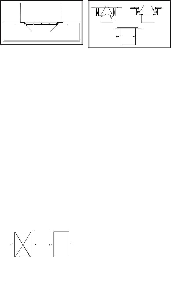
Installing The Furnace
Sides and back of the furnace may be enclosed by wall framing such as in a closet or alcove.The dimensions of the room or alcove must be able to accommodate the overall size of the furnace and the installation clearances outlined on page 2 and Figures 1 - 4 (page 6). The furnace shall be appropriately connected to the supply and return air distribution system as shown in Figures 14 & 15 (page 11).
1.Remove furnace outer door(s) and bottom fuel line knockout.
2.Place furnace onto duct connector and center with ß oor opening.
3.Slide onto mounting plate. (Bottom rear slots on furnace should engage with mounting plate tabs.)
4.Secure front with one (1) fastener at each corner (Figures 14 or 15).
NOTE: Additional fasteners may be used at rear, sides or through door frame, as desired, to secure furnace to closet or alcove framing.
10
SCREWS |
MOUNTING |
|
|
DUCT |
PLATE |
|
|
CONNECTOR |
|
FUEL
LINE
HOLES
14Ó SUPPLY CONNECTION
Figure 13. Round Duct Connector Installed
MTG. PLATE TABS |
SLIDE FURNACE |
|
ALL THE WAY BACK |
||
|
||
|
ONTO MTG. PLATE |
SECURE FURNACE
WITH 2 FASTENERS AT FRONT
CORNER HOLES
Knockout Over Holes 
SUPPLY AIR DUCT
Figure 14. ÒAÓ & ÒBÓ Cabinet Furnaces
SLIDE FURNACE
BACK AGAINST
MTG. PLATE
MTG. PLATE TABS
SUPPLY
AIR DUCT
 SECURE FURNACE
WITH 2 FASTENERS
AT FRONT CORNER HOLES
FUEL LINE HOLES
Figure 15. ÒAÓ Cabinet Furnace on Coil Cabinet
ROOF JACK
SLANT DECK
FLASHING
PITCHED
ROOF
"X" (SEE TABLE 5)
CEILING
CAVITY ÒAÓ
Roof
Opening
CEILING |
ÒBÓ |
|
|
|
|
Flue Pipe |
|
|
|
|
|
||||
|
|
Combustion Air Pipe |
|||||
|
|
|
|
||||
|
|
|
|
|
|
|
|
Furnace 56" or 76"
Figure 16. Ceiling Cavity Depth
ROOF JACK INSTALLATION
Required ceiling and roof cut-out openings (see Figure 11) must be carefully located to avoid misalignment of the furnace and Roof Jack. Note: Install only Roof Jack Assemblies listed in Table 4 on this heating appliance.
Roof Jack Selection
1.Determine depth of ceiling cavity from center of roof opening to center of ceiling opening. (See Dimension ÒAÓ in Figure 16.)
2.Determine ceiling height and subtract height of furnace. (See Dimension ÒBÓ in Figure 16.)
3.Add dimensions A + B (and X from Table 5 and Figure 18 if slant deck ß ashing is used). The total length of (A + B + X) must be within the minimum and maximum range of one of the Roof Jacks listed in Table 4.
Application Notes:
¥FAW, FAWT, SAW and SAWT Series Roof Jacks with a 5Ó diameter inner vent pipe may be used with all models of M1 Series gas and M5 Series oil furnaces.
F = Flat Flashing: ß exes from 0/12 to 1/12 roof slope. See Figure 17 (page 12).
S = Slant Flashing: 2.5/12 Slope ß exes from 1/12 to 4/12 roof slope, 4/12 ß exes from 3/12 to 5/12. See Figure 18.
¥Stainless steel roof jacks are available.
¥M1/M5 furnaces may be used with roof jacks as tall as 170Ó (except M1M 056 & M1B 066 models, which are limited to 120Ó). An internal roof jack extension (p/n 901935 - 10Ó, p/n 903107 - 18Ó) can be used to increase roof jack height. All connections inside the home must be made below the ceiling.
NOTE: If the roof jack crown is covered or blocked with snow, the furnace will not operate properly.
MODEL NUMBER
APPROX. LENGTH
BELOW FLASHING
(F,S)AW(T)1523-(0,2,4)(A,S) |
15Ó - 23Ó |
||||||||||||||||||||||
(F,S)AW(T)2135-(0,2,4)(A,S) |
21Ó - 35Ó |
||||||||||||||||||||||
(F,S)AW(T)2747-(0,2,4)(A,S) |
27Ó - 47Ó |
||||||||||||||||||||||
(F,S)AW(T)3563-(0,2,4)(A,S) |
35Ó - 63Ó |
||||||||||||||||||||||
(F,S)AW(T)5195-(0,2,4)(A,S) |
51Ó - 95Ó |
||||||||||||||||||||||
|
|
S AW |
T 27 47 - 2 |
|
S |
||||||||||||||||||
F = FLAT FLASHING |
|
|
|
|
|
|
|
|
|
|
|
|
|
|
|
|
|
|
|
|
|
|
FLUE STEEL TYPE |
|
|
|
|
|
|
|
|
|
|
|
|
|
|
|
|
|
|
|
|
|
|||
|
|
|
|
|
|
|
|
|
|
|
|
|
|
|
|
|
|
|
A= ALUMINIZED |
||||
|
|
|
|
|
|
|
|
|
|
|
|
|
|
|
|
|
|
|
|||||
S = SLANT FLASHING |
|
|
|
|
MIN. |
ADJ. |
|
|
|
|
|
|
S=STAINLESS |
||||||||||
AW= ALL WEATHER |
|
|
|
|
|
LENGTH |
|
|
|
|
|
FLASHING |
|||||||||||
|
|
|
|
|
|
|
|
|
|
|
|
|
|
|
|
||||||||
|
|
|
|
|
|
|
|
|
|
|
|
|
|
|
|||||||||
|
|
|
|
|
|
|
|
|
|
|
|
|
|
|
|
|
|
|
|
|
|
PITCH/12" RISE |
|
|
|
|
|
|
|
|
|
|
|
|
|
|
|
|
|
|
|
|
|
|
|
0=FLAT |
|
|
|
|
|
|
|
|
|
|
|
|
|
|
|
|
|
|
|
|
|
2=2.5/12 |
|||
TYPE: |
|
|
|
|
|
|
|
|
|
|
|
4=4/12 |
|||||||||||
BLANK = NON-TRANSIT |
|
|
|
|
|
|
|
|
|
MAX. ADJ. |
|||||||||||||
|
|
|
|
|
|
|
|
|
|||||||||||||||
T= TRANSIT MODE |
|
|
|
|
|
|
|
|
|||||||||||||||
|
|
|
|
|
|
|
|
LENGTH |
|||||||||||||||
|
|
|
|
|
|
|
|
|
|
|
|
|
|
|
|
|
|||||||
Table 4. Roof Jack Assemblies
11
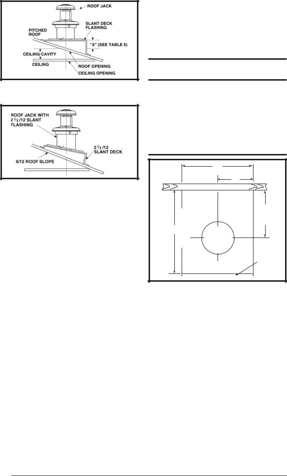
1.Locate center of Roof Jack opening, measure 13 1/2Ó from the rear wall of closet or alcove along the center line of furnace and ß oor opening. See Figure 19.
2.Cut ceiling and roof holes as follows:
¥Ceiling = 8 3/4Ó (222 mm) diameter
¥Roof = 9 3/8Ó (238 mm) diameter
 IMPORTANT:
Figure 17. Example of Flat Jack
with Flashing
Figure 18. Example of 2½/12 Slant Jack
with Flashing
If the home is located in regions where snow accumulation exceeds 7Ó(HUD snowload zones) use an external roof jack extension (p/n 901937). Extensions are optional accessories and may be purchased through your NORDYNE distributor.
Locating and Cutting Roof & Ceiling Openings
DO NOT ALLOW DEBRIS TO FALL INTO THE FURNACE. THIS COULD CAUSE UNSAFE OPERATION AND VOIDS THE FURNACE WARRANTY. Use the top cap that comes with the furnace packaging (or alternate protector) to prevent debris from falling into the furnace before the Þ nal roof jack connection is made
R e f e r t o t h e i n s t a l l a t i o n i n s t r u c t i o n s p r o v i d e d w i t h o p t i o n a l a i r c o n d i t i o n i n g p a c k a g e s w h e n i n s t a l l i n g furnaces with optional cooling c o i l c a b i n e t o r w i t h o p t i o n a l C * s e r i e s i n d o o r c o i l s .
|
|
20" |
|
|
|
C |
|
|
|
L |
|
|
|
10" |
|
|
REAR WALL OF CLOSET OR ALCOVE |
|
|
24" |
OUTLINE |
|
13 1/2" |
FURNACE |
CEILING |
|
|
|
CUT-OUT FOR |
C |
|
|
|
||
|
FLUE AND |
L |
|
|
|
||
|
ROOF JACK |
|
|
|
|
|
FURNACE |
|
|
|
OUTER |
|
|
|
DOOR |
Figure 19. Cut-Out Dimensions for Flue & Roof Jack
ROOF JACK SERIES |
IF ROOF PITCH IS: |
SLANT DECK |
ÒXÓ FACTOR |
|
FLASHING NUMBER |
IS: |
|||
|
|
|||
|
|
|
|
|
|
2Ó in 12Ó |
903893 (2.5/12) |
2-1/8Ó |
|
|
2-1/2Ó in 12Ó |
903893 (2.5/12) |
2-1/2Ó |
|
ÒF Series |
3Ó in 12Ó |
903894 (3/12) |
2-7/8Ó |
|
|
3-1/2Ó in 12Ó |
903894 (3/12) |
3-1/4Ó |
|
|
4Ó in 12Ó |
903895 (4/12) |
3-5/8Ó |
|
|
4-1/2Ó in 12Ó |
903895 (2.5/12) |
2-1/8Ó |
|
ÒSÓ Series (2.5 / 12 |
5Ó in 12Ó |
903895 (2.5/12) |
2-1/2Ó |
|
5-1/2Ó in 12Ó |
903894 (3/12) |
2-7/8Ó |
||
Pitch only) |
||||
6Ó in 12Ó |
903894 (3/12) |
3-1/4Ó |
||
|
||||
|
6-1/2Ó in 12Ó |
903895 (4/12) |
3-5/8Ó |
Optional Deck Flashings for Flat and 2.5/12 Pitch Roof Jacks. 4/12 Pitch Roof Jacks not applicable.
Table 5. Slant Deck Flashings
12
 Loading...