


E3
Downfl ow, Upfl ow Electric Furnaces
Owners Manual/Installation Instructions
E3 Series (Air Conditioner/Heat Pump Air Handler)
IMPORTANT: Read this owner information
to become familiar with the capabilities and
use of your heating appliance. Keep this
literature where you will have easy access
to it in the future. If a problem occurs, check
the instructions and follow recommendations given. If these suggestions don’t
eliminate your problem, call the appropriate
NORDYNE distributor. A distributor service
list is included with this appliance.
WARNING:
Do not store or use gasoline or other
fl ammable vapors and liquids in the
vicinity of this or any other appliance.
Improper installation, adjustment,
alteration, service or maintenance
can cause injury, property damage,
or death. Refer to this manual. For
assistance or additional information
consult a qualifi ed dealer or service
agency. To avoid personal injury or
property damage, ask a service
technician to inspect the furnace and to
replace any part of the control system
which has been under water.
SECTION 1. OWNER INFORMATION
OPERATING INSTRUCTIONS
Before Operating System
Before operating your heating/cooling system
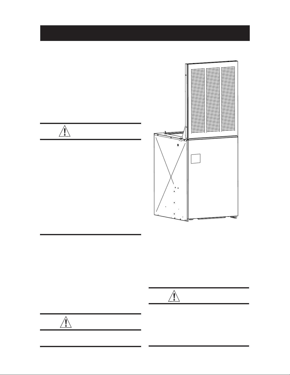
(see Figure 1), make sure that:
• Control panel covers are closed.
• Blower and/or relay control plugs are
plugged in.
• Fan switch is set to “AUTO” (E3EH units
only).
CAUTION:
No user serviceable parts inside
control panel. DO NOT OPEN.
• Circuit breakers are in “ON” position.
• All power supply switches for furnace and
outside unit (if installed) are turned on.
• Furnace door is closed and properly
latched.
Refer to the owner’s manual supplied with the
optional heat pump or air conditioner for further
information.
CAUTION:
For optional A/C or H/P systems,
always wait at least fi ve minutes after
the system shuts off before restarting
the system. Observe this procedure
when operating the system per the
following instructions.

2
10 20 30
Temperature Selector
Temperature
Scales
System Switch
(optional sub-base)
Fan Switch
(optional sub-base)
50 60 70 80 90
SYSTEM
HEAT OFF COOL
VENTILATE
ON AUTO
Indoor Coil
(optional)
Coil Air Filters
(used with indoor coil)
Furnace Air Filter
(NOT used with
coil air filters)
Blower
Circuit Breakers
Data Label
Control Panel
Cover (left)
Figure 1. Furnace Parts Identifi cation
Product Type
E - Electric Furnace
Generation
EB - A/C Blower Equipped Relay
EX - Multi-Speed, X13 Motor
Used with Platinum Series
3 - Third Series
Product Identifier
Control Panel Cover (right)
E 3 EB - 010 H
Electrical Code
H - 240-1-60
Primary Capacity
010 - 10 kw 012 - 12 kw
015 - 15 kw 017 - 17 kw
020 - 20 kw 023 - 23 kw
Model Identifi cation
3

To Operate System in Cooling Mode
NOTE: The “FAN ON/FAN AUTO” (fan switch)
and “HEAT/OFF/COOL” (system switch) are
located either on your thermostat (if it’s supplied
with a sub-base) or on the relay box added to
your furnace.
1. Make sure blower selector switch is on
“Auto.”
2. Set fan switch to “AUTO.”
3. Set system switch to “COOL.”
4. Set thermostat temperature selector to
desired comfort level.
To Operate System in Heating Mode
1. Make sure blower selector switch is on
“Auto.”
2. Set fan switch to “AUTO.”
3. Set system switch to “HEAT.”
4. Set thermostat temperature selector switch
to desired comfort level.
NOTE: Allow at least one hour for the room temperature to stabilize before you make a second
adjustment to the thermostat setting. Once the
desired comfort level is established, make only
small adjustments to the thermostat setting to
meet changing temperature conditions.
To Operate Blower Continuously
1. Set blower selector switch to “ON” for summer
air circulation only (see Figure 1),
OR
2. If thermostat is equipped with optional
heating/cooling sub-base or relay box (see
Figure 1), set fan switch to “ON.”
To Balance Air Distribution
1. On a typical day, set thermostat selector to
desired comfort level and operate system for
several hours with all air registers open.
2. With system on, check temperature in all
rooms.
3. Partially close registers in rooms that are
too warm (in heating mode) or too cool
(in cooling mode) and in rooms that are
infrequently occupied.
4. Re-check room temperature and adjust
registers as needed.
To Shut Off System
1. Make sure blower selector switch is on
“Auto”.
2. Set thermostat temperature selector to
lowest temperature setting, OR...
3. For thermostats with optional sub-base (see
Figure 1), or for systems with relay box, set
system switch to “OFF.”
WARNING:
To prevent hazard of electrical shock
and injury from moving parts, be
certain the thermostat is off and the
furnace circuit breaker(s) are in the
“OFF” position before servicing. Close
and properly latch the outer door after
doing the following recommended
maintenance.
MAINTENANCE INSTRUCTIONS
Regularly
NOTE: If a cooling coil is installed, furnace
fi lter is not used.
1. Replace furnace air fi lter (see Figure 1),
OR...
2. Remove coil fi lters, wash, and allow to dry.
Re-install coil fi lters to original positions.
3. Vacuum or wipe clean interior of furnace
cabinet.
4. Clean all lint and dust from around furnace.
Every Six Months
1. Vacuum or wipe away any dust or lint on
blower motor.
Before Each Heating Season
NOTE: If a cooling coil is installed, furnace
fi lter is not used.
1. Replace furnace air fi lter (see Figure 1),
OR
2. Remove coil fi lters, wash, and allow to dry.
Re-install coil fi lters to original positions.
3. Have a qualifi ed serviceman inspect all
furnace components and fi eld wiring and
clean and service heating system as
needed. If this furnace was installed with
aluminum power supply wiring, have serviceman periodically check all connections
to prevent possible equipment failure and/or
fi re hazard. Do not attempt any service
function yourself which requires opening
furnace control panel covers.
4

BEFORE YOU CALL A SERVICEMAN
1. Make sure thermostat temperature selector
is set above room temperature for heating
or below room temperature for cooling. If
thermostat is equipped with heating/cooling sub-base, make sure system switch
(see Figure 1) is set to “HEAT” for furnace
operation or set to “COOL” for optional airconditioning operation.
2. Check main household service panel to
see if appropriate circuit disconnect(s) for
appliance power supply is on.
3. Refer to instructions under Before Operating
System for pre-operation checks.
4. Refer to instructions under Before Each
Heating Season for maintenance procedures and recommended service checks.
5. Refer to owner’s manual provided with
optional air conditioner or heat pump (if
installed) for service and maintenance.
NOTE: All servicing of this heating appliance
other than the normal maintenance described in
this section must be done by authorized trained
service personnel. Do not open the control
panels (see Figure 1) at any time.
Please specify the complete model and serial
numbers shown on the furnace data label (see
Figure 1) for all warranty service and when ordering replacement parts or optional equipment.
Refer to the replacement parts list provided with
the furnace for part numbers.
OPTIONAL AIR CONDITIONER
AND HEAT PUMP
Your E3 Series electric furnace is approved for
use with an optional central air conditioner or a
heat pump. To adapt this heating appliance to
a “total comfort system,” contact your nearest
NORDYNE distributor.
SECTION 2.
INSTALLER INFORMATION
GENERAL
These instructions and specifi cations are primarily intended to assist qualifi ed individuals
experienced in the proper installation of home
heating and air conditioning appliances. Some
local codes require licensed personnel for the
installation and service of this type of equipment. Approved installation, operation, and
maintenance of this central heating system
appliance must be in accordance with the listed
specifi cations contained in these instructions
and other documents supplied with the furnace
and/or optional air conditioning equipment. Refer
to local authorities having jurisdiction for further
information.
Before beginning installation, read these instructions thoroughly. Follow all warnings and cautions
in the instructions and on the unit.
Improper installation, service adjustment, or
maintenance can cause explosion, fi re, electrical shock or other conditions which may result
in personal injury or property damage. Unless
otherwise noted in these instructions, use only
factory-authorized kits and accessories when
modifying this product.
Overview of E3 Furnace
E3E(-) Series electric furnaces are available in
two models. E3EH models are equipped with the
standard two-speed blower. E3EH models can
be easily converted for use with NORDYNE splitsystem air conditioners and heat pumps. E3EB
models are air-conditioning ready; that is, they
are equipped with a multi-speed (four-speed)
blower, blower relay, and cabinet insulation kit.
See Table 3 for cooling and heat pump availability
with factory installed blower.
Optional air conditioners and heat pumps are
listed by Underwriters’ Laboratories (UL) or
Environmental Testing Laboratories (ETL) and
certifi ed by ARI and the Canadian Standards
Association (CSA), or Warnock Hersey or ETLC.
These cooling systems include energy-saving components to provide maximum cooling
performance at electrical energy usage levels
established by federal standards. Refer to the
operation instruction label on your furnace for
the optional air conditioning equipment approved
for your heating appliance.
For typical unducted return air downfl ow applications, an air-conditioner or heat-pump coil can be
installed by mounting the coil directly on top of
the furnace without adding sheet metal cavities
or cutting and trimming wood panels.
A return air grille for closet or alcove installations
is available. For downfl ow alcove installations,
the grille (with frame provided) may be attached
to the top of the furnace and all paneling and
trim fl ushed to it. This installation provides an
access door for future installation of NORDYNE
air conditioning or heat pump coils on top of
the furnace.
5
Power entrance for all models may be through the
right side or through the bottom of the unit (when
viewing the unit in a downfl ow position).
UNIT CHECKOUT
Before installing this furnace:
1. Inspect unit for possible shipping damage.
If shipping damage is found, fi le claim with
transportation company.
2. Record furnace model number and serial
number (see furnace data label) for future
reference.
3. Carefully read all instructions supplied with
optional equipment to be installed with
furnace.
CODES, SPECIFICATIONS, AND
REQUIREMENTS
Furnace Codes
Installation and wiring of this furnace, as well as
the design and construction of the home duct
system, must be in accordance with one or more
of the following codes:
• HUD MANUFACTURED HOME CONSTRUC-
TION AND SAFETY STANDARD (Title 24,
Part 3280)
• American National Standards (ANSI) A119.11,
C1-NFPA 7 (National Electrical Code)
• CANADIAN STANDARDS (C.S.A.) Z240.6.1,
and Z240.9.1.
All local codes having jurisdiction shall also
apply.
Air Duct Codes and Specifi cations
Air ducts must be installed in accordance with
National Fire Protection Association standards
NFPA 90A and NFPA 90B, these instructions,
and all applicable local codes.
• Materials: Air ducts must be aluminum,
tin plate, galvanized sheet steel, or other
approved materials for outlet or return air
ducts.
• Construction: Snap-Lock or Pittsburgh-Lock
seams are preferred. All other types of seams
must be made tight to prevent leakage.
• Sizing: Supply duct system must be designed
for proper air distribution. Static pressure
measured externally to furnace shall not exceed static pressure rating listed on furnace
nameplate.
• Location of Openings: Duct system must be
designed so that no supply registers are located in duct system directly below furnace.
Listing agency(s)
Approved Installation Confi gurations
Accessibility for Servicing Minimum of 18"(46cm) required in front of unit.
Minimum Clearance to
Combustibles
Minimum return air opening
required (total free area)
Return air grille (closet or alcove
installation)
May vary by model, check the unit data label for
applicable agency listing mark.
Approved for: single/multistory residential or mobile/
modular/manufactured structures. Upfl ow, downfl ow,
(freestanding/closet/alcove)
0" from all surfaces of furnace cabinet, ducts, optional
coil housing and plenum connector. No separate
subbase required for installations on combustible
fl ooring.
200 in (1290 cm ) heating only*
235 in (1516 cm ) A/C or H/P up to 4 ton installed
250 in (1613 cm ) A/C or H/P up to 4 ton w/1" clearanced
installed
390 in (2516 cm ) A/C or H/P up to 5 ton installed
*or return air grille and frame assembly p/n 902989 or
wall mount grille p/n 902999
Use return air grille and frame assembly P/N 902989 or
equivalent for alcove installation.
Use wall mount return air grilled P/N 902999 or
equivalent for closet installation.
155 in (1000 cm ) must be added for 5 ton A/C or H/P
system.
Table 1. Miscellaneous Listings & Installation Requirements
6

Return Air Codes and Requirements
Unducted return air systems may be used for
closet or alcove installations.
NOTE: Applicable installation codes may limit the
furnace to installation in a single-story residence
only. Furnace installations other than closet or
alcove installations require ducted return air
systems.
Air return to the furnace must have a minimum
free area opening (see Table 1).
Acceptable fl oor or ceiling return air systems
for closet installations with return air entering
through an opening in the closet fl oor or ceiling
must meet all of the following requirements:
• Return air opening into closet, regardless of
its location, must not be smaller than size
specifi ed on unit data label.
• If located in fl oor of closet, return air opening
must be provided with means of preventing
its inadvertent closure by a fl at object placed
over opening.
• Materials located in return air duct system
must have a fl ame-spread classifi cation of
200 or less.
• Noncombustible pans having 1” upturned
fl anges must be located beneath openings
in a fl oor-return duct system.
• Wiring materials located in retur n duct system
must conform to NEC Article 300-22(c).
• Gas piping must not run in or through return
air duct system.
• If return air opening is located below top
of furnace, a minimum clearance must be
provided between opening and furnace (see
“Accessibility for servicing” in Table 1).
Closed-Off Space Requirements
Living space not served by, and closed off from,
the return air ducts to the furnace by doors, sliding
partitions, and other means must be provided
with permanent, uncloseable openings in the
doors or partitions to allow air to return to the
furnace from all parts of the home. Return air
grilles, with a minimum open area of one square
inch for every fi ve square feet of living space
closed off from the furnace, must be provided
in the door or room partition.
OPTIONAL EQUIPMENT
Contact your nearest NORDYNE distributor for a
complete list of electric furnace accessories.
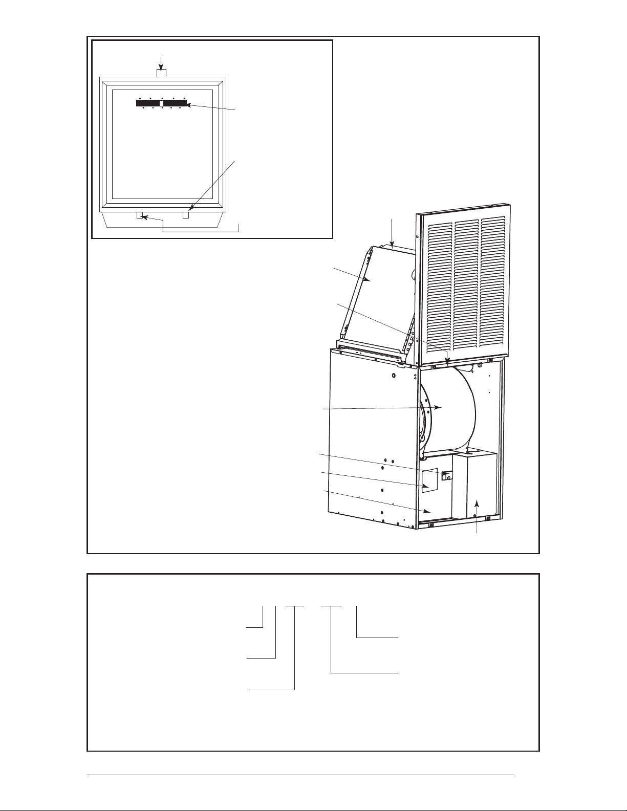
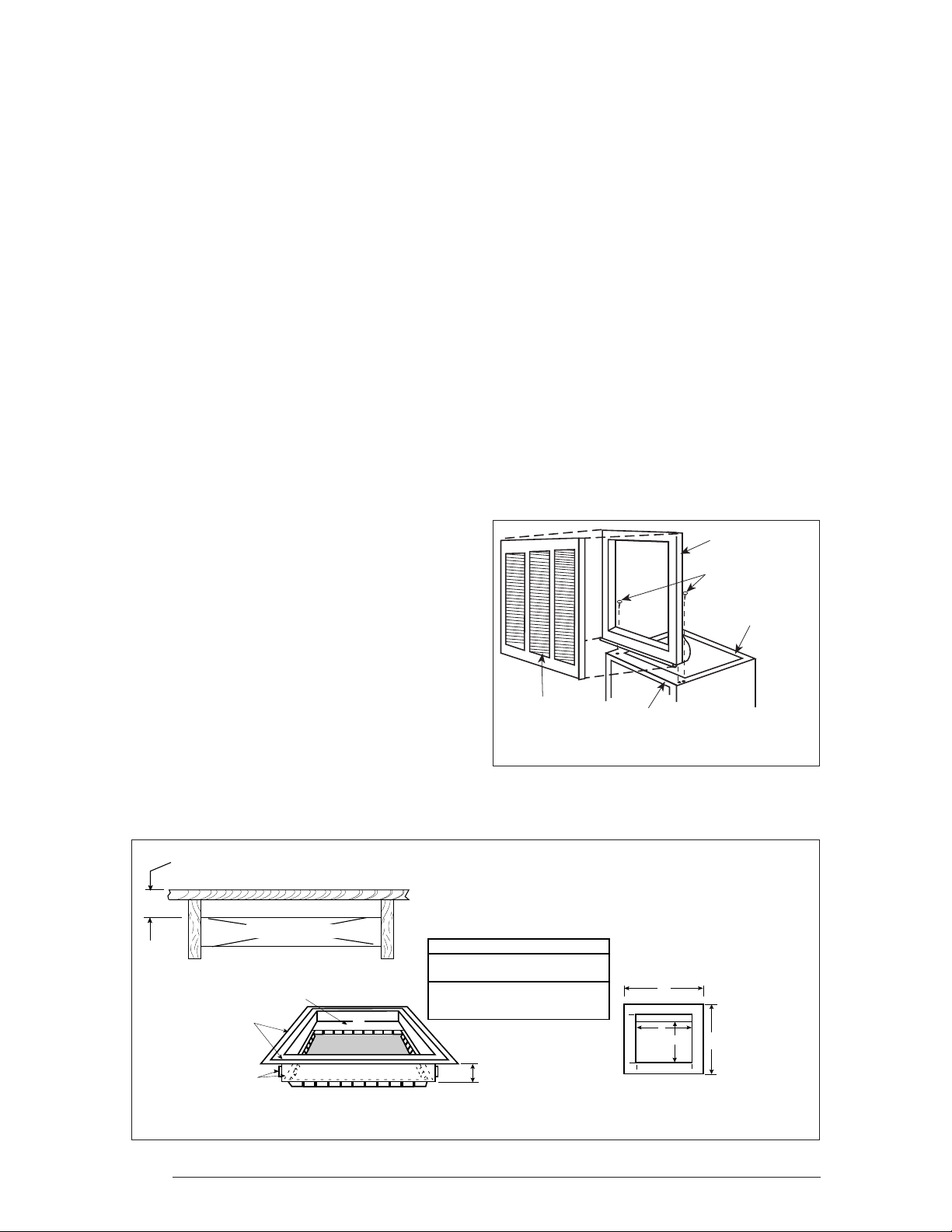
Return Air Grille
A return air grille and frame assembly (see Figure
2) is available for use in unducted return air installations. In downfl ow alcove installations, the grille
and frame assembly may be mounted directly
to the top of the furnace. In closet installations,
a wall mount grille is available for attachment
to a door or wall.
Optional Automatic Furnace
Damper #901083 -
Furnace may (not required) be equipped with
the optional automatic damper when a packaged
air conditioner is installed and connected to the
warm air duct system. This damper prevents
cooled air from discharging through the furnace
cabinet, causing excessive cooling of the immediate area. Refer to instructions supplied with the
damper for details.
Multi-Speed Blower Conversion
Package (4 or 5 ton):
Upgrade blower packages are available for
adding air conditioning or heat pump systems.
See furnace “Options and Compatibility” label
for systems available.
TYPICAL INSTALLATION OF
DOWNFLOW SYSTEMS OR
PLATINUM SYSTEM
The following steps describe installation instructions for an under-the-fl oor supply duct system
with a return air system that can be either
unducted or ducted. Duct connectors (Table 4)
are recommended for this application.
NOTE: Before installing this furnace, consider all
clearances for the installation and future servicing
of the furnace. Refer to Table 1.
Return Air and Filtering Systems
Furnaces may be installed with unducted or
ducted return air. For unducted return air
systems, either the optional grille and frame
assembly or the optional wall mount grille is recommended. For ducted return air systems with
air conditioners or heat pumps, either providing
an access panel in the duct or using the optional
coil cabinet is recommended. The duct system
must be properly sized so as to account for any
additional external static pressure produced from
the chosen fi ltering method.
7
20" (508 mm)
Cabinet
Insulation
Upflow Coil Cabinet
23 3/4" (603 mm)
29"
(737 mm)
1
2
3
4
7
8
27"
(686 mm)
29"
(737 mm)
20"
(508 mm)
23 3/4"
(603 mm)
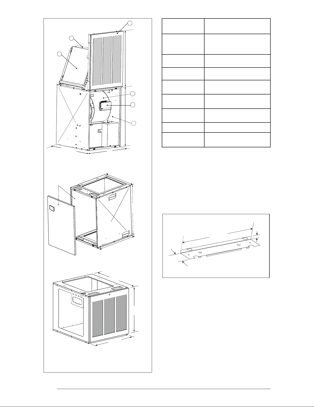
Item Number
(See Figure)
Description
4-Speed Blower
1
4 Ton - See notes: 1 & 5
5 Ton - See Note: 1
2
3
4
5
6
A.C./H.P. Relay Control
See Note: 1
Cabinet insulation Kit
See Notes: 1 & 5
A-Coil Conversion Kit
See Note: 2
Coil Cabinet
See Note: 3
Upfl ow Stand
See Note: 4
7 A/C and H/P Indoor Coils
8
Notes:
1) For A/C and H/P use.
2) Includes coil fi lters.
3) For upfl ow or downfl ow installations.
4) For upfl ow A/C or H/P installations (includes one fi lter; use
fi lter from furnace to complete fi ltering system in this accessory).
5) Standard in EB models.
Return Air Grille and
Frame
Table 2. Optional Air Conditioning and
Heat Pump Equipment
11/16"
20-1/8"
(511 mm)
3"
(76 mm)
24 3/4” (628 mm)
Figure 3. Optional Rear Mounting Plate
(17 mm)
(P/N 389080)
NOTE: See Table 2 for descriptions
Figure 2. Optional Accessories
8
Upflow Stand
and notes
20” (508 mm)
20”
(508 mm)
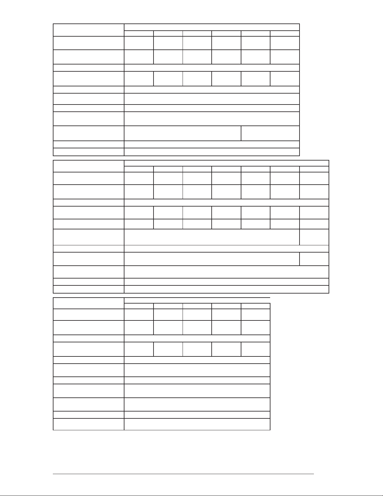
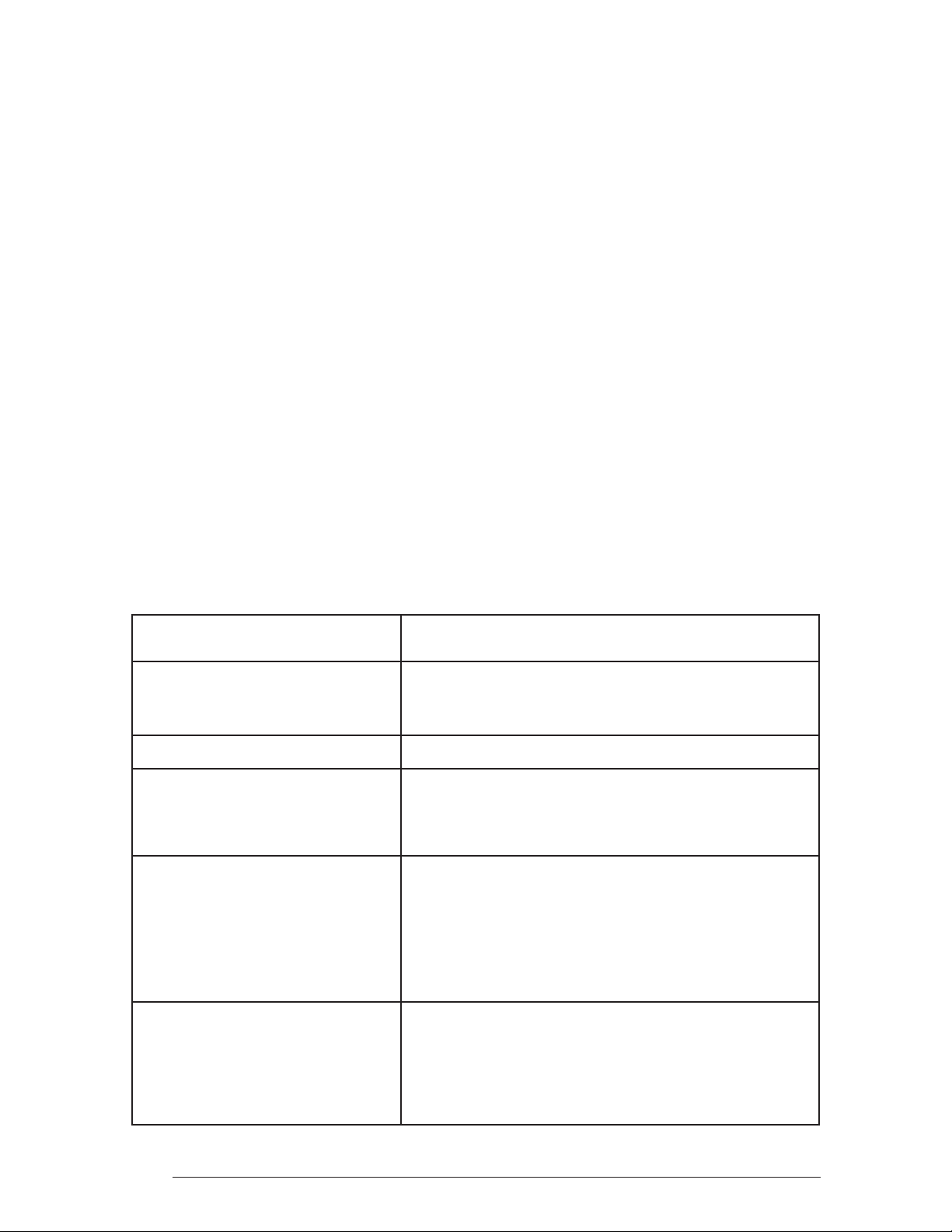
Electric Furnace Models
Rated Heating Output, Btuh
(see note 1)
Watts (Total kw, Heating
Elements and Blower)
Supply Voltage 240 Volts/60Hz/1-Phase
Heating Elements,
No.(Total kw)
Blower Wheel Size 10.5" Dia., 8" Wide
Motor Speed,
H.P. Rating, Amps
Test ESP, in. w.c. Max 0.3
Optional Cooling Available with
factory installed blower
Optional Heat Pump Available
with factory installed blower
Air Filter (Standard) 16" x 20" x 1" (nominal)
Furnace Dimensions Width-20" (508mm), Height-29" (737mm) (see note 2), Depth-24 1/2" (623mm)
Table 3. Unit Specifi cations
E3EH
010H 012H 015H 017H 020H 023H
35,000 41,000 53,000 57,000 70,000 75,000
10.4 12.0 15.4 16.6 20.4 22.0
2 (10.0) 2 (11.6) 3 (15.0) 3 (16.2) 4 (20.0) 4 (21.6)
2 Speed, 1/5 HP, 2.0
2.0 - 3.0 Ton (see note 3)
2.0 - 3.0 Ton (see note 3) n/a (see note 3)
Electric Furnace Models
Rated Heating Output, Btuh
(see note 1)
Watts (Total kw, Heating
Elements and Blower)
Supply Voltage 240 Volts/60Hz/1-Phase
Heating Elements,
No.(Total kw)
Blower Wheel Size
Motor Speed,
H.P. Rating, Amps
Test ESP, in. w.c. Max 0.3
Optional Cooling Available with
factory installed blower
Optional Heat Pump Available
with factory installed blower
Air Filter (Standard) 16" x 20" x 1" (nominal)
Furnace Dimensions Width-20" (508mm), Height-29" (737mm) (see note 2), Depth-24 1/2" (623mm)
Electric Furnace Models
Rated Heating Output, Btuh
(see note 1)
Watts (Total kw, Heating
Elements and Blower)
Supply Voltage 240 Volts/60Hz/1-Phase
Heating Elements,
No.(Total kw)
Blower Wheel Size 10.5" Dia., 8" Wide
Motor Speed,
H.P. Rating, Amps
Test ESP, in. w.c. Max 0.3
Optional Cooling Available with
factory installed blower
Optional Heat Pump Available
with factory installed blower
Air Filter (Standard) 16" x 20" x 1" (nominal)
Furnace Dimensions
1. Heating output rated at listed voltage. For outputs at voltages other than 240V, multiply Btuh rating by the following
factors: x 0.92 (230V), x 0.84 (220V), x 0.75 (208V)
2. Height is 56” with return air grille installed, 58” with coil cabinet and 72” with coil cabinet and upfl ow stand.
3. The factory installed blower for the EH models can be replaced with a multi-speed blower allowing the units to
accept up to 5 tons of air conditioning or 4 tons heat pump.
4. The factory installed blower for the EB models can be replaced with a multi-speed blower allowing the units to
accept up to 5 tons of air conditioning.
010H 012H 015H 017H 020H 023H 023H 5-Ton
35,000 41,000 53,000 57,000 70,000 75,000 75,000
10.4 12.0 15.4 16.6 20.4 22.0 22.0
2 (10.0) 2 (11.6) 3 (15.0) 3 (16.2) 4 (20.0) 4 (21.6) 4 (21.6)
4 Speed, 1/3 HP, 2.9
2.0 - 4.0 Ton (see note 4) 2.0 - 5.0 Ton
010H 012H 015H 017H 020H
35,000 41,000 53,000 57,000 70,000
11.4 13.0 16.4 17.6 21.4
2 (10.0) 2 (11.6) 3 (15.0) 3 (16.2) 4 (20.0)
Multi-Speed, 3/4 HP, 6.0
2.0 - 4.0 Ton
2.0 - 4.0 Ton
Width-20" (508mm), Height-29" (737mm) (see note 2)
Depth-24 1/2" (623mm)
E3EB
2.0 - 4.0 Ton
E3EX
11" Dia.,
8" W
4 Spd,
3/4HP 3.8
Amps
9
NOTE: Refer to the instructions supplied with
A
B
19”
(483 mm)
19"
(483 mm)
TOP VIEW
X
Reducer
*Felt Seal
Corner
Spacers
C
*OPENING TO DUCT
A= 13-1/4" (337 mm)
B= 10-3/4" (274 mm)
WITH PLATE (C) REMOVED
OPENING BECOMES
13-1/4” x 13-1/4”
*Indicates only applicable for Finger Tab Duct Connector
x
SUPPLY AIR DUCT
FLOOR CAVITY
Frame
Top of
Furnace
Fasteners (4)
Grille
Furnace Filter
(not used with
A/C or H/P)
any additional accessories for further installation details.
(see Figure 3) supplied with the duct connectors is recommended for use with this type of
installation.
Filtering Methods - Non-Ducted Return Air
1. Without A/C or H/P uncased coil:
- use the fi lter supplied with the furnace;
ensure that the fi lter is installed mat side
down between the fi lter retainer and furnace
top (see Figure 4).
2. With A/C or H/P uncased coil:
- use the optional coil fi lters; the fi lter supplied with the furnace is not used; REMOVE
AND DISCARD THIS FILTER.
3. With optional coil housing:
- see coil cabinet instructions for specifi c
fi ltering methods.
Filtering Methods - Ducted Return Air
1. Without optional coil housing:
- install a fi lter with a minimum unrestricted
medium area of 324 square inches in the
duct above the coil that is accessible for
monthly cleaning or replacement by homeowner.
2. With optional coil housing:
-install a fi lter with a minimum unrestricted
medium area of 324 square inches in the
duct above the coil that is accessible for
monthly cleaning or replacement by homeowner.
Selecting Duct Connector
Non Platinum Duct Connector
1. Determine depth of fl oor cavity from surface
of fl oor to top of supply air duct (see Figure
5).
2. Select appropriate model from Table 4
which matches X-dimension of fl oor cavity.
To maximize air delivery, remove reducer
(C in Figure 5) to obtain largest open area
that will fi t duct/fl oor construction.
NOTE: Duct connectors may be
installed in any one of four positions.
Platinum Duct Connector
1. The 14” round duct connector (903896) is
designed to connect directly to a 14” fl exduct.
Optional Duct Connectors for
Downfl ow Systems
Duct connectors are recommended for heated
air distribution in under-the-fl oor duct systems.
With this system, furnaces may be installed on
combustible fl ooring without a separate subbase. Also, the furnace rear mounting plate
10
Figure 5. Duct Connector Selection (Non-Platinum)
Figure 4. Grille Support Frame and Grille
Assembly
 Loading...