


Counterflow Gas or Oil Heating Appliance
INSTALLATION INSTRUCTIONS
CMF2 80-PG CONVERTIBLE (65, 75, & 85 KBTU/H INPUTS)
CMF2 80-PO CONVERTIBLE (65, 75, & 85 KBTU/H INPUTS)
For installation in:
• Manufactured Homes
• Recreational Vehicles, Park Models, & Manufactured Buildings
• Modular Homes/Buildings
ATTENTION INSTALLERS:
It is your responsibility to know this product better than your customer. This includes being able to install the product according to strict safety guidelines and instructing the customer on how to operate and maintain the equipment for the life of the product. Safety should always be the deciding factor when installing this product and using common sense plays an important role as well. Pay attention to all safety warnings and any other special notes highlighted in the manual. Improper installation of the furnace or failure to follow safety warnings could result in serious injury, death, or property damage.
These instructions are primarily intended to assist qualified individuals experienced in the proper installation of this appliance. Some local codes require licensed installation/service personnel for this type of equipment. Please read all instructions carefully before starting the installation. Return these instructions to the customer’s package for future reference.
 WARNING:
FIRE OR EXPLOSION HAZARD
•Failure to follow safety warnings exactly could result in serious injury or property damage.
•Installation and service must be performed by a qualified installer, service agency or the gas supplier.
•Do not store or use gasoline or other flammable vapors and liquids in the vicinity of this or any other appliance.
WHAT TO DO IF YOU SMELL GAS
•Do not try to light any appliance.
•Do not touch any electrical switch; do not use any phone in your building.
•Leave the building immediately.
•Immediately call your gas supplier from a neighbors phone. Follow the gas suppliers instructions.
•If you cannot reach your gas supplier, call the fire department.
DO NOT DESTROY. KEEP IN A SAFE PLACE FOR FUTURE REFERENCE.

TABLE OF CONTENTS |
|
Important Safety Information .................................... |
3 |
Requirements & Codes .............................................. |
3 |
Minimum Installation Clearances .............................. |
4 |
Combustion Air & Venting Requirements ................ |
5 |
General Information................................................... |
6 |
Combustion Air Quality.............................................. |
6 |
Direct Vent Furnaces................................................. |
7 |
Manufactured Housing Installations ....................... |
7 |
Residential Installations ......................................... |
7 |
Venting through a Chimney ....................................... |
8 |
Ventiaire III or IV Air Quality Package ....................... |
8 |
Circulating Air Requirements.................................... |
9 |
Plenums & Air Ducts ................................................. |
9 |
Supply Air Connections.......................................... |
9 |
Dampers ................................................................ |
9 |
Unconditioned Spaces .............................................. |
9 |
Closet Installations .................................................... |
9 |
Furnace Filter .......................................................... |
10 |
Furnace Installation.................................................. |
10 |
General Information................................................. |
10 |
Before You Install this Furnace ................................ |
10 |
Locating the Unit ..................................................... |
10 |
MA-200 Base Installation ........................................ |
11 |
Installing the furnace on an MA-200 Base .............. |
12 |
MA-100 Universal Base Installation ........................ |
12 |
Installing the furnace on an MA-100 Base .............. |
12 |
Combustion Air Duct / Pipe Installation ................... |
13 |
SRJ Roof Jack Installation ...................................... |
13 |
Damper Installation ................................................. |
14 |
CB-200A Cottage Base Installation......................... |
14 |
Fuel Connections ..................................................... |
15 |
Gas Piping - PG Series Only................................... |
15 |
Leak Check .......................................................... |
15 |
High Altitude Application ...................................... |
16 |
Converting to LP Gas........................................... |
16 |
Oil Piping - PO Series Only..................................... |
17 |
Fuel Line Hook-up: Single Line System ............... |
17 |
Fuel Line Hook-up: Two Line System................... |
17 |
Hook-up Procedure.............................................. |
17 |
Eliminating Air Leaks ........................................... |
17 |
Fuel Oil Type ........................................................ |
17 |
Electrical Connections............................................. |
18 |
Pre-Electrical Checklist ........................................... |
18 |
Line Voltage............................................................. |
18 |
Wiring Connections ................................................. |
18 |
Grounding................................................................ |
18 |
Thermostat Connections ......................................... |
19 |
Heat Anticipator ................................................... |
19 |
Blower Speed .......................................................... |
19 |
Constant Blower Operation .................................. |
19 |
Startup & Adjustments ............................................ |
20 |
Important Safety Information................................... |
20 |
Pre-Start Checklist .................................................. |
20 |
Refrigerant Charging............................................... |
20 |
Operating Instructions - PG Direct Ignition.............. |
20 |
Shutting Off the Gas Supply ................................ |
20 |
Checking the Input of the Furnace....................... |
21 |
Checking the Inlet Gas Line Pressure.................. |
21 |
Checking the Manifold Pressure .......................... |
21 |
Adjusting the Manifold Pressure .......................... |
21 |
Installing the Pressure Gauge.............................. |
21 |
Adjusting the Burner ............................................ |
21 |
Operating Instructions - PO Oil Burners.................. |
22 |
Start-up Procedure............................................... |
22 |
Air Bleed-Single Pipe Installation......................... |
22 |
Oil Burner Shutdown Procedure .......................... |
22 |
Flame Adjustment ................................................ |
22 |
Electrode Setting.................................................. |
22 |
Switching from Interrupted to Intermittent |
|
Ignition Control..................................................... |
22 |
Firing Rate Conversion............................................ |
23 |
Operating Sequence................................................. |
23 |
PG Gas Furnaces ................................................... |
23 |
PO Oil Furnaces...................................................... |
23 |
Troubleshooting........................................................ |
24 |
PG Direct Ignition - Gas Gun................................... |
24 |
PO Oil Furnace ....................................................... |
25 |
Control Module Status Indicator.............................. |
26 |
Component Functions ............................................. |
26 |
Unit Maintenance...................................................... |
27 |
Figures & Tables ....................................................... |
28 |
Figure 18. CMF2 Physical Dimensions ................ |
28 |
Figure 19. CMF2 Wiring Diagram......................... |
29 |
Figure 20. Furnace Component Location............. |
30 |
Installation / Performance Checklist....................... |
32 |
2
IMPORTANT SAFETY INFORMATION
INSTALLER: Please read all instructions before servicing this equipment. Pay attention to all safety warnings and any other special notes highlighted in the manual. Safety markings are used frequently throughout this manual to designate a degree or level of seriousness and should not be ignored. WARNING indicates a potentially hazardous situation that if not avoided, could result in personal injury or death. CAUTION indicates a potentially hazardous situation that if not avoided, may result in minor or moderate injury or property damage.
 WARNING:
ELECTRICAL SHOCK, FIRE OR EXPLOSION HAZARD
Failure to follow safety warnings exactly could result in serious injury or property damage.
Improper servicing could result in dangerous operation, serious injury, death or property damage.
•Before servicing, disconnect all electrical power to air handler.
•When servicing controls, label all wires prior to disconnecting. Reconnect wires correctly.
•Verify proper operation after servicing.
 WARNING:
Do not use this appliance if any part has been submerged under water. Immediately call a qualified service technician to inspect the appliance and to replace any part of the control system and any gas control that has been submerged underwater.
 WARNING:
PROPOSITION 65 WARNING: This product contains chemicals known to the state of California to cause cancer, birth defects or other reproductive harm.
REQUIREMENTS & CODES
 WARNING:
This unit must be installed in accordance with instructions outlined in this manual during the installation, service, and operation of this unit. Unqualified individuals should not attempt to interpret these instructions or install this equipment. Failure to follow safety recommendations could result in possible damage to the equipment, serious personal injury or death.
•All manufactured and residential housing installations must be installed in accordance with these instructions, all applicable local building codes and the current revision of the National Fuel Gas Code (ANSI Z223.1 / NFPA54), Installation of Oil Burning Equipment (ANSI/ NFPA31) or the National Electric Code (ANSI/NFPA 70), the Manufactured Home Construction & Safety Standard,Title 24 CFR, Part 3280, or when this standard is not applicable, the Standard for Manufactured Home Installation Manufactured Home Sites, Communities and Setups (ANSI 225.1).Residential installations must also conform to the standard for Chimey’s, Fireplaces, Vents, & Solid Fuel Burning Appliances (NFPA 211).
•Use only with type of gas or oil approved for this furnace. Refer to the furnace rating plate.
•Install this furnace only in a location and position as specified on page 4.
•Provide adequate combustion and ventilation air to the furnace space as specified on pages 5 - 8.
•Provide adequate clearances around the vent air intake terminal as specified in Figure 1 (page 8).
•Combustion products must be discharged outdoors. Connect this furnace to an approved vent system only, as specified on pages 7 - 8.
•Never test for gas leaks with an open flame. Use a commercially available soap solution to check all connections. See pages 15 - 16.
•This furnace is designed to operate with a maximum external pressure rise of 0.5 inches of water column. Consult Table 6 (page 19), and the rating plate for the proper circulating air flow and temperature rise. It is important that the duct system be designed to provide the correct flow rates and external pressure rise. An improperly designed duct system can result in nuisance shutdowns, and comfort or noise issues.
•When supply ducts carry air circulated by the furnace to areas outside the space containing the furnace, the return air shall also be handled by duct(s) sealed to the furnace casing and terminating in the conditioned space. See pages 9 - 10.
•This furnace may not be used for temporary heating of buildings or structures under construction.
3
•The Commonwealth of Massachusetts requires compliance with regulation 248 CMR 4.00 and 5.00 for installation of through – the – wall vented gas appliances as follows:
1.For direct-vent appliances, mechanical-vent heating appliances or domestic hot water equipment, where the bottom of the vent terminal and the air intake is installed below four feet above grade the following requirements must be satisfied:
a.) A carbon monoxide (CO) detector and alarm shall be placed on each floor level where there are bedrooms. The detector shall comply with NFPA 720 (2005 Edition) and be mounted in the living area outside the bedroom(s).
b.) A (CO) detector shall be located in the room that houses the appliance or equipment and shall:
•Be powered by the same electrical circuit as the appliance or equipment. Only one service switch shall power the appliance and the (CO) detector;
•Have battery back-up power;
•Meet ANSI/UL 2034 Standards and comply with NFPA 720 (2005 Edition);and Approved and listed by a Nationally RecognizedTesting Laboratory as recognized under 527 CMR.
c.) A Product-approved vent terminal must be used, and if applicable, a product-approved air intake must be used. Installation shall be in strict compliance with the manufacturer’s instructions. A copy of the installation instructions shall remain with the appliance or equipment at the completion of the installation.
d.) A metal or plastic identification plate shall be mounted at the exterior of the building, four feet directly above the location of vent terminal. The plate shall be of sufficient size, easily read from a distance of eight feet away, and read “Gas Vent Directly Below”.
2.For direct-vent appliances, mechanical-vent heating appliances or domestic hot water equipment where the bottom of the vent terminal and the air intake is installed above four feet above grade the following requirements must be satisfied:
a.) A (CO) detector and alarm shall be placed on each floor level where there are bedrooms. The detector shall comply with NFPA 720 (2005 Edition) and be mounted in the living area outside the bedroom(s).
b.) The (CO) detector shall:
•Be located in the room that houses the appliance or equipment;
•Be hard-wired or battery powered or both.
•Shall comply with NFPA 720 (2005 Edition).
c.)A product-approved vent terminal must be used, and if applicable, a product-approved air intake must be used.Installation shall be in strict compliance with the manufacturer’s instructions.A copy of the installation instructions shall remain with the appliance or equipment at the completion of the installation.
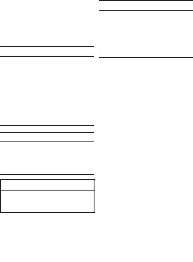
Minimum Installation Clearances
•Access for positioning and servicing the unit must be considered when locating unit. The need to provide clearance for access to panels or doors may require clearance distances over and above the requirements.
•This appliance must be installed in accordance with clearances listed inTable 1.The furnace must be installed with ample clearance for easy access to the air filter, blower assembly, burner assembly, controls, and vent connections.
•Locate and install this unit in position as specified on pages 10 & 11. This unit is designed only for Indoor installations and should be located with consideration of minimizing the length of the supply and return ducts.
INSTALLATION CLEARANCES
|
CLOSET |
ALCOVE |
Front * |
6" |
18" |
Rear |
0" |
0" |
Sides |
0" |
0" |
Top |
17" |
17" |
Duct w/in 3ft of furnace |
1/4" |
1/4" |
Vent |
6” |
6” |
Plenum |
1" |
1" |
Roof Jack Barrel |
0” |
0” |
REAR
VENT
LEFT |
|
|
|
|
|
|
|
|
|
|
|
|
|
|
|
RIGHT |
|
SIDE |
|
|
|
|
|
|
|
|
|
|
|
|
|
|
|
SIDE |
|
|
|
|
|
|
|
|
|
|
|
|
|||||||
|
|
|
|
|
|
|
|
|
|
|
|
|
|
|
|
|
|
|
|
|
|
|
|
|
|
|
|
|
|
|
|
|
|
|
|
FRONT
†NOTES:
* Service Clearance
Alcove Installations - Allow 18 in. minimum clearance from front of unit to nearest wall or partition for servicing.
Closet installations - Require a return air grill installed in the door or a partially louvered door across the opening for proper air circulation. For clearances 6” or greater, the closet must have an open free area of 235 in2 minimum. For special clearances between 1” - 5”, requirements are a louvered door with a minimum of 250 in2 (1613 cm2) free area. A fully louvered closet door is strongly recommended for both installation types.
Table 1. Minimum Clearance Requirements
4

•Sufficient clearance for unobstructed airflow through a louvered door must be maintained in order to achieve rated performance. Air return to the furnace must have the minimum required total free area:
200 in2 (1290 cm2 ) for furnace only. May also include return air grille and frame assembly P/N 902989 or wall mount grille P/N 902999).
235 in2 (1516 cm2 ) with 4 ton A.C. or H.P. installed. 250 in2. (1613 cm2 ) with 4 ton A.C. or H.P. installed & 1” special clearance.
390 in2 (2516 cm2 ) with up to 5 ton A.C. or H.P. installed.
The information listed below is for reference purposes only and does not necessarily have jurisdiction over local or state codes. Always consult with local authorities before installing any gas appliance.
Duct Systems
•US and CANADA:Air Conditioning Contractors Association (ACCA) Manual D, Sheet Metal and Air Conditioning Contractors National Association (SMACNA), or American Society of Heating, Refrigeration, and Air Conditioning Engineers (ASHRAE) Fundamentals Handbook
Electrical Connections
•US: National Electrical Code (NEC) ANSI/NFPA 70
•CANADA: Canadian Electrical Code CSA C22.1
General Installation
•US: Current edition of the NFGC and the NFPA 90B. For copies, contact the National Fire Protection Association Inc., Batterymarch Park, Quincy, MA 02269; or American Gas Association, 400 N. Capitol, N.W., Washington DC 20001 or www.NFPA.org
•CANADA:NSCNGPIC.For a copy, contact Standard Sales, CSA International, 178 Rexdale Boulevard, Etobicoke (Toronto), Ontario, M9W 1R3 Canada
Safety
•US: (NFGC) NFPA 54–1999/ANSI Z223.1 and the Installation Standards, Warm Air Heating and Air Conditioning Systems ANSI/NFPA 90B.
•CANADA: CAN/CGA-B149.1 and .2–M00 National Standard of Canada. (NSCNGPIC)
COMBUSTION AIR & VENTING
REQUIREMENTS
 WARNING:
CARBON MONOXIDE POISONING HAZARD
Failure to follow the steps outlined below for each appliance connected to the venting system being placed into operation could result in carbon monoxide poisoning or death.
The following steps shall be followed with each individual appliance connected to the venting system being placed in operation, while all other appliances connected to the venting system are not in operation:
1.Seal any unused openings in the venting system.
2.Inspect the venting system for proper size and horizontal pitch, as required in the National Fuel Gas Code, ANSI Z223.1/NFPA 54 or the CSA B149.1, Natural Gas and Propane Installation Codes and these instructions. Determine that there is no blockage or restriction, leakage, corrosion and other deficiencies which could cause an unsafe condition.
3.As far as practical, close all building doors and windows and all doors between the space in which the appliance(s) connected to the venting system are located and other spaces of the building.
4.Close fireplace dampers.
5.Turn on clothes dryers and any appliance not connected to the venting system. Turn on any exhaust fans, such as range hoods and bathroom exhausts, so they are operating at maximum speed. Do not operate a summer exhaust fan.
6.Follow the lighting instructions. Place the appliance being inspected into operation. Adjust the thermostat so appliance is operating continuously.
7.Test for spillage from draft hood equipped appliances at the draft hood relief opening after 5 minutes of main burner operation. Use the flame of a match or candle.
8.If improper venting is observed during any of the above tests, the venting system must be corrected in accordance with the National Fuel Gas Code, ANSI Z223.1/NFPA 54 and/or CSA B149.1, Natural Gas and Propane Installation Codes.
9.After it has been determined that each appliance connected to the venting system properly vents when tested as outlined above, return doors, windows, exhaust fans, fireplace dampers and any other gas-fired burning appliance to their previous conditions of use.
5

General Information
 WARNING:
This furnace must be installed by a qualified installing agency and in accordance with applicable local codes and ordinances that governthistypeofequipment.Failuretoproperly install the furnace, base assembly, and venting system as described herein may damage the equipment and/or the home, can create a fire or asphyxiation hazard, violates U.S. listing requirements, and will void the warranty. This furnace is NOT approved for installation with split system air conditioning. Use a NORDYNE packaged air conditioning system.
•Instructions for determining the adequacy of combustion air for an installation can be found in the current revision of the NFGC (ANSI Z223.1 / NFPA54). Consult local codes for special requirements.These requirements are for US installations as found in the NFGC.
•The requirements in Canada (B149.1) are structured differently. Consult with B149.1 and local code officials for Canadian installations.
Depending on the type of installation (See Table 1), the CMF2 Series furnace can draw combustion air from outside the home (direct vent) or from the space being conditioned. These high quality, direct vent furnaces are used for manufactured housing, recreational vehicle, and residential applications. They are certified to the UL307 standards (UL307-A for oil models; UL307-B for gas models), and can be installed in a variety of applications, as shown in Table 2.
The CMF2 furnace is available in power gas (PG models) or power oil (PO models) and can be converted from power oil to power gas, and vice versa. The power gas models are designed for operation with either natural or propane
(LP) gas. The firing rate of the CMF2 80 Convertible Series can be field-installed using a certified NORDYNE conversion kit by a qualified service technician. Refer to page 6 for conversion information.
 CAUTION:
Exhaust fans, clothes dryers, fireplaces and other appliances that force air from the house to the outdoors can create a negative pressure inside the house, resulting in improper furnace operation or unsafe conditions such as flame roll out. It is imperative that sufficient air exchange with the outdoors is provided to prevent depressurization.Additional information about how to test for negative pressure problems can be found in the NFGC.
Combustion Air Quality
 CAUTION:
Combustion air must not be drawn from a corrosive atmosphere.
Provisions for adequate combustion air and ventilation air must be in accordance with the ANSI Z223.1/NFPA 54, (National Fuel Gas Code), ANSI/NFPA 31 (Installation of Oil Burning Equipment), and all applicable local codes.
The installation of the furnace must allow for adequate supply of fresh air for combustion. Air openings on top of the furnace and openings in closet doors or walls must never be restricted. The combustion air opening of the furnace must be designed and located to prevent blockage by snow.
If the furnace is operated without adequate air for combustion, the flame roll-out switch will open and shut off the gas supply to the burners.NOTE:This safety device
TYPE OF |
FURNACE |
TYPE OF |
DUCTED |
DIRECT VENT |
|
INSTALLATION |
BASE |
EXHAUST |
APPLICATION |
SYSTEM REQUIRED |
|
|
|
|
|
|
|
Manufactured Housing or |
MA-100 or MA-200 |
NORDYNE SRJ |
Yes |
Yes |
|
Recreational Vehicle |
Universal Base |
Roofjack Only |
|||
|
|
||||
|
|
|
|
|
|
Residential† |
MA-100 or MA-200 |
NORDYNE SRJ Roofjack |
Yes |
Yes |
|
Universal Base |
or an Existing Chimney* |
||||
|
|
|
|||
|
|
|
|
|
|
Residential† |
CB-200A Cottage Base |
NORDYNE SRJ Roofjack |
Yes |
Yes |
|
or an Existing Chimney* |
|||||
|
|
|
|
||
|
|
|
|
|
|
Residential† |
CB-200A Cottage Base |
NORDYNE SRJ Roofjack |
No |
No |
|
or an Existing Chimney* |
|||||
|
|
|
|
||
|
|
|
|
|
† Residential is defined as a single-story non-manufactured housing installation.
* Consult the Venting Requirements section (page #) for more details on properly venting this appliance through an existing chimney.
Table 2. CMF2 Installation Types
6

is a manually reset switch. DO NOT install jumper wires across these switches to defeat their function or reset a switch without identifying and correcting the fault condition. If a switch must be replaced, use only the correct sized part specified in the Replacement Parts List provided online.
The combustion air from the outside needs to be clear of chemicals that can cause corrosion. Excessive exposure to contaminated combustion air will result in safety and performance related problems.The list below are examples of chemical contaminants found in a wide variety of some common commercial and household products:
Permanent wave solutions Chlorinated waxes and cleaners
Chlorine based swimming pool chemicals Water softening chemicals
De-icing salts or chemicals Carbon Tetrachloride
Cleaning solvents (perchloroethylene) Printing inks, paint removers, varnishes, etc. Hydrochloric Acid
Cements and glues Antistatic fabric softeners
Masonry acid washing materials
When drawing combustion air from underneath the home, a vent or duct of at least 18 in2 of free area should be installed outside and completely unobstructed.When using the combustion air duct, make sure it extends through the floor. When using the direct vent kit, the combustion air opening must be located in the same pressure zone as the flue exit of the roof jack or chimney. Refer to the instructions provided with the kit for more information.
Direct Vent Furnaces
Direct Vent furnaces draw combustion air directly from the outdoors and then vent the combustion products back outside, isolating the entire system from the indoor space. It is important to make sure that the whole system is sealed and clearances to combustibles are maintained regardless of the installation being in a confined or unconfined space.
For direct vent applications, either the combustion air duct provided with the MA Series base kit or the direct vent kit can be used.The direct vent kit must be ordered separately. Only for a special CB-200A cottage base installation can the CMF2 draw the combustion air from the conditioned space. The CB-200A cottage base kit must be ordered separately.Refer to the replacement parts listing provided with the furnace to order the direct vent kit or the cottage base kit. Follow the instructions provided with the kits for proper installation.
When unsure about combustion air supply availability, a direct vent system should be used. For small rooms, confined spaces, tight construction or similar situations in which the combustion air requirements of the furnace might not be met, a direct vent system must be used.
Manufactured Housing Installations
For all manufactured housing applications, the CMF2 furnace must be vented using the SRJ series roofjack. The instructions for selecting the proper roofjack for your installation are detailed later in these instructions.
Residential Installations
 WARNING:
This furnace must never be connected to a chimney flue serving a separate appliance designed to burn solid fuel.
For residential applications (See Table 2), the CMF2 furnace may be vented through the SRJ series roofjack or through an existing chimney. Figure 10 (page 14) displays instructions for selecting the proper roofjack for your installation. If venting through an existing chimney, the venting system must be in accordance with these instructions, all applicable local building codes, the National Fuel Gas Code (ANSI Z223.1/NFPA 54), the Installation of Oil-Burning Equipment standard (ANSI/NFPA 31), and the standard for Chimneys, Fireplaces, Vents, and Solid Fuel-Burning Appliances (NFPA 211).
 WARNING:
When venting through a chimney, check the chimney for soot, leaks, obstructions, and proper installation.
The materials used to construct the venting system must be capable of withstanding exposure to temperatures of at least 700° F. The existing chimney servicing this furnace must be vertical. Horizontal distances to an existing chimney must be as short as possible, and the connecting pipe must slope upward to the chimney at not less than a 45° angle. The total length of the sloping pipe must not exceed 6 ft. The venting system must have no obstructions or sharp bends where soot and other foreign matter can accumulate.
If an inspection determines that the chimney is obstructed, the chimney must be cleaned and the connecting flue pipe must be cleaned or replaced.
If venting a CMF2 power oil furnace into an existing chimney, a barometric damper can be installed at the vent connection of the furnace to regulate the draft. The barometric damper must be properly installed per the manufacturer’s instructions. Refer to all applicable codes to determine whether or not a barometric damper can be used for your CMF2 power oil furnace installation. The barometric damper used must be installed such that air from the conditioned space can only enter the flue passageway. Do not use a double acting barometric
7
damper. All flue pipe joints should be fastened with sheet metal screws for rigidity.
The chimney height, required draft, and number of appliances served by the chimney must be in accordance with all applicable codes. To prevent down draft, the chimney should extend at least 2 feet above the peak of the roof. See Figure 1.
It is recommended that the furnace flue serve no other appliances.When the chimney serves only the furnace, the flue area must be sized according to all applicable codes. The minimum internal area of the flue must be equal to at least the area of the furnace flue exit. When two or more appliances must vent through a common flue, the area of the common flue should be sized in accordance with all applicable codes.
When an existing furnace is removed or replaced in a venting system, the venting system may not be properly sized to vent the attached appliances.The venting system must be checked to ensure proper venting.Improperly sized venting systems can result in the formation of condensate, leakage, spillage, etc. Refer to the National Fuel Gas Code (ANSI Z223.1/NFPA 54), and the Installation of Oil Burning Equipment standard (ANSI/NFPA 31) for correcting improper venting systems.
Venting Through a Chimney
When venting the CMF2 through an existing chimney, the materials, sizing, and installation of the chimney must be in accordance with the ANSI Z223.1/NFPA 54, (National Fuel Gas Code), ANSI/NFPA 31 (Installation of Oil Burning Equipment), NFPA 211 (Chimneys, Fireplaces,Vents, and Solid Fuel-Burning Appliances) and all applicable local codes.The materials used must be capable of withstanding exposure to temperatures of at least 700° F. The CMF2 power gas units are fan-assisted.
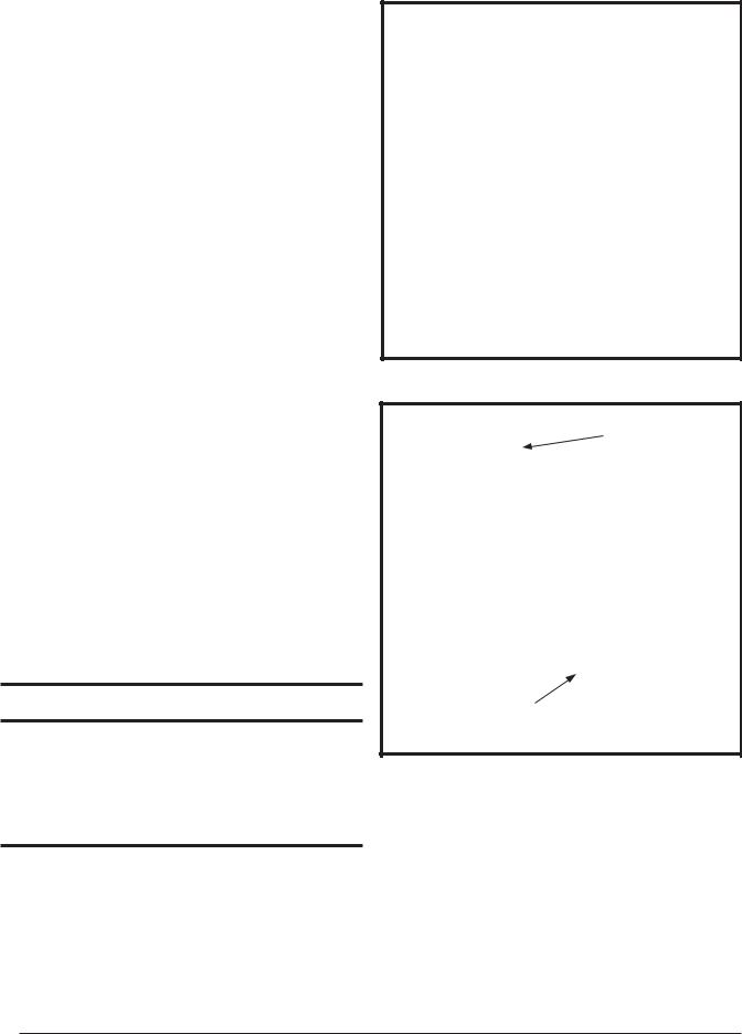
Ventilaire III or IV Air Quality Package (Accessory)
 CAUTION:
MAINTAIN 2 1/2” MINIMUM CLEARANCE BETWEENFLUEPIPEANDFLEXDUCT.FAILURE TO COMPLY WITH THIS RESTRICTION COULD CAUSE EQUIPMENT DAMAGE. VENTILAIRE III ILLUSTRATED OTHER LISTED VARIATIONS AVAILABLE. CHECK WITH MANUFACTURER.
The Ventilaire air quality packages are available to meet the ventilation requirements as outlined in H.U.D.Standard Part 3280.103 (b) (2).These packages introduce outdoor air into the living space during furnace blower operation. The VentilAire IV also serves to exhaust moist and/or hot air from the attic space.See Figure 2 for typical installation. Complete installation instructions are supplied with each air quality package.
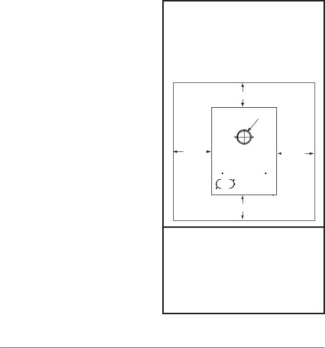
3 FEET MIN.
ROOF JACK ASSY.
ROOF CAP ASSY.
DRAW BAND
FLEX DUCT
CEILING TRIM COLLAR
VENT PIPE
DRAW BAND
CONNECTOR
FURNACE
Figure 1. Typical Installation
VentilAire III
VentilAire IV
Figure 2. VentilAire III & IV
8

CIRCULATING AIR REQUIREMENTS
 WARNING:
All supply ducts must be secured to the furnace with sheet metal screws and adequately sealed. When supply air is provided through the bottom of the unit, the joint between the furnace and the plenum must be air tight.
The surface that the furnace is mounted on must provide sound physical support of the furnace with no gaps, cracks or sagging between the furnace and the floor or platform.
Supply air ducts must not be connected to any other heat producing device such as a fireplace insert, stove, etc. This may result in fire, explosion, carbon monoxide poisoning, personal injury, or property damage.
Plenums & Air Ducts
This unit is designed only for use with a bottom return supply duct and must be installed in accordance with the standards of the National Fire Protection Association Standard for Installation of Air Conditioning Systems (NFPA 90A), Standard for Installation of Residence Type Warm Air Heating and Air Conditioning Systems (NFPA 90B), and all applicable local codes. NFPA publications are available by writing to: National Fire Protection Association, Batterymarch Park, Quincy, ME 02269 or visit www.NFPA.org on the web.
•Design the air ducts according to methods described by the Air Conditioning Contractors of America (ACCA).
•Air ducts must be aluminum, tin plate, galvanized sheet steel, or other approved materials for outlet or return air ducts. Snap-Lock or Pittsburgh-Lock seams are preferred. All other types of seams must be made tight to prevent leakage.
•It is good practice to seal all connections and joints with industrial grade sealing tape or liquid sealant. Requirements for sealing ducts vary from region to region.Consult with local codes for requirements specific to your area.
•Gas piping must not run in or through any of the air duct system.
Supply Air Connections
•The supply duct system must be designed so that the static pressure measured external to the furnace does not exceed the listed static pressure shown on the furnace rating plate. The supply air must be delivered to the heated space by duct(s) secured to the furnace casing, running full length and without interruption.
•Duct system must be designed so that no supply registers are located in duct system directly below the furnace.
Dampers
An automated shut off damper is required when the home is air conditioned by a self-contained unit. A damper is required to prevent chilled air from flowing over the furnace heat exchanger. This damper is designed to fit in the feeder duct cavity, directly under the furnace. For proper installation, refer to the instructions provided with the damper. See replacement parts list provided online.
Unconditioned Spaces
All duct work passing through unconditioned space must be properly insulated to minimize duct losses and prevent condensation. Use insulation with an outer vapor barrier. Refer to local codes for insulation material requirements
Closet Installations
 WARNING:
Failure to comply with the the following instructions may result in fire, asphyxiation or carbon monoxide poisoning.
For proper air circulation, closet installations require a return air grill installed in the door or side wall that exchanges with the living area of the home as shown in Figure 3 (page 10). A partially louvered door may also be used across the opening. Return air openings should not be located to draw air directly from a bathroom. Grilles placed in a side wall require a 6” clearance from the wall to the furnace so that the air may enter the front grille of the furnace. In addition, all return air systems, including the floor and ceiling systems, must meet the following conditions:
•The return air opening, regardless of its location in the closet, must not be smaller than size specified on unit data label. If located in the floor, the opening must be provided with a means of preventing its inadvertent closure by flat object(s) placed over the opening.
•The return-air opening into the closet, regardless of its location, must have an open free area of 200 in2 (1290 cm2 ) minimum.
•The cross-sectional area of the return duct system (in floor or ceiling) leading into the closet must not be less than 200 in2 (1290 cm2 ).
•The total free area of the openings in the floor or the ceiling registers serving the return air duct system must not be not less than 300 in2 (1935 cm2 ).
•Materials located in the return duct system shall have a flame spread classification of 200 or less.
•Noncombustible pans having one inch upturned flanges are located beneath openings in a floor return duct system.
•Hollow spaces used as ducts or plenums for environmental air may contain mineral-insulated metal sheathed cable, aluminum sheathed cable, electrical metallic tubing, rigid metal conduit, fl exible metal conduit (not to exceed 4 ft), or metal-clad cables.Wiring
9

Figure 3. Closet Installation
materials, fixtures, are to be suitable for the expected ambient temperatures to which they will be subjected.
•The negative pressure in the closet must not be less than minus 0.05 inches water column with the closet door closed and the fan operating at high speed. A reading below minus 0.05” indicates a dirty filter or a restricted return air system.
•For floor return systems, the manufactured housing manufacturer or installer shall affix a prominent marking on or near the appliance where it is easily read when the closet door is open. The marking shall read: “CAUTION, HAZARD OF ASPHYXIATION. DO NOT COVER OR RESTRICT FLOOR RETURN AIR OPENING.” or equivalent. NOTE: This label is supplied with the instruction manual in each furnace.
•For closet installation with less than 6” front clearance, but not less than 1”, a louvered door must be used having a minimum 200 in2 (1290 cm2 ) free area opening directly in line with openings in the furnace door. A fully louvered door having the minimum free area is also permitted if the front tolerance is not less than 4”. Adjust duct registers to obtain a temperature rise within the range specified on the furnace nameplate.
Furnace Filter
 WARNING:
Never operate the furnace without a filter in place. Accumulating dust in the return air can build up on internal components, resulting in loss of efficiency, equipment damage, and possible fire.
•CMF2 furnaces are supplied with a single air filter when shipped from the factory. Accessing the filter does not require tools and can be easily removed from the inside of the access door.The filter is secured to the door with
a retaining bracket. It is recommended that the filter be cleaned or replaced monthly. Newly built or recently renovated homes may require more frequent changing until the construction dust has minimized.
•Replacement filters are available at most local retailers. Inspect filters frequently and replace when necessary with filter of same dimensional size. Filters designed to remove smaller particles such as pollen, may require additional maintenance.
FURNACE INSTALLATION
NOTE:Since all installations are different, the sequence of these steps may differ from the actual installation. These installation procedures are suggested for typical furnace installations. Only qualified HVAC technicians should install this furnace.
General Information
The CMF2 furnace is designed only for indoor installations and can be readily connected to the high static duct system of a home.Units are approved for single/multistory residential or mobile/modular/manufactured structures in freestanding/closet/alcove downflow only configurations.
This appliance will provide many years of safe and dependable comfort, providing it is properly installed and maintained. Abuse, improper use, and/or improper maintenance can shorten the life of the appliance and create unsafe hazards.Please read all instructions before installing the unit.
Approved installation, operation, and maintenance of this appliance must be in accordance with the listed specifications contained in these instructions and other documents supplied with the furnace and/or optional air conditioning equipment.Unless it is noted differently in this manual, only use factory authorized kits and accessories when modifying this appliance. Refer to local authorities having jurisdiction for further information.
Before You Install this Furnace
This equipment is securely packaged at the time of shipment and upon arrival should be carefully inspected for damage prior to installing the equipment at the job site.Claims for damage (apparent or concealed) should be filed immediately with the carrier.
Check the electrical supply and verify the power supply is adequate for unit operation.The system must be wired and provided with circuit protection in accordance with local building codes. If there is any question concerning the power supply, contact the local power company.
Verify the air delivery of the furnace is adequate to handle the static pressure drop of the coil, filter, and duct work.
Locating the Unit
•Survey the job site to determine the best location for installing the unit. Consideration should be given to availability of electric power, service access, and noise.
10
 Loading...