


M1BC086
Nordyne M1BC086, M1MD056, M1MD070, M1MD077, M1MD090 Installation Guide
...
The following information is updatedfrom the enclosed Installation Instructions.
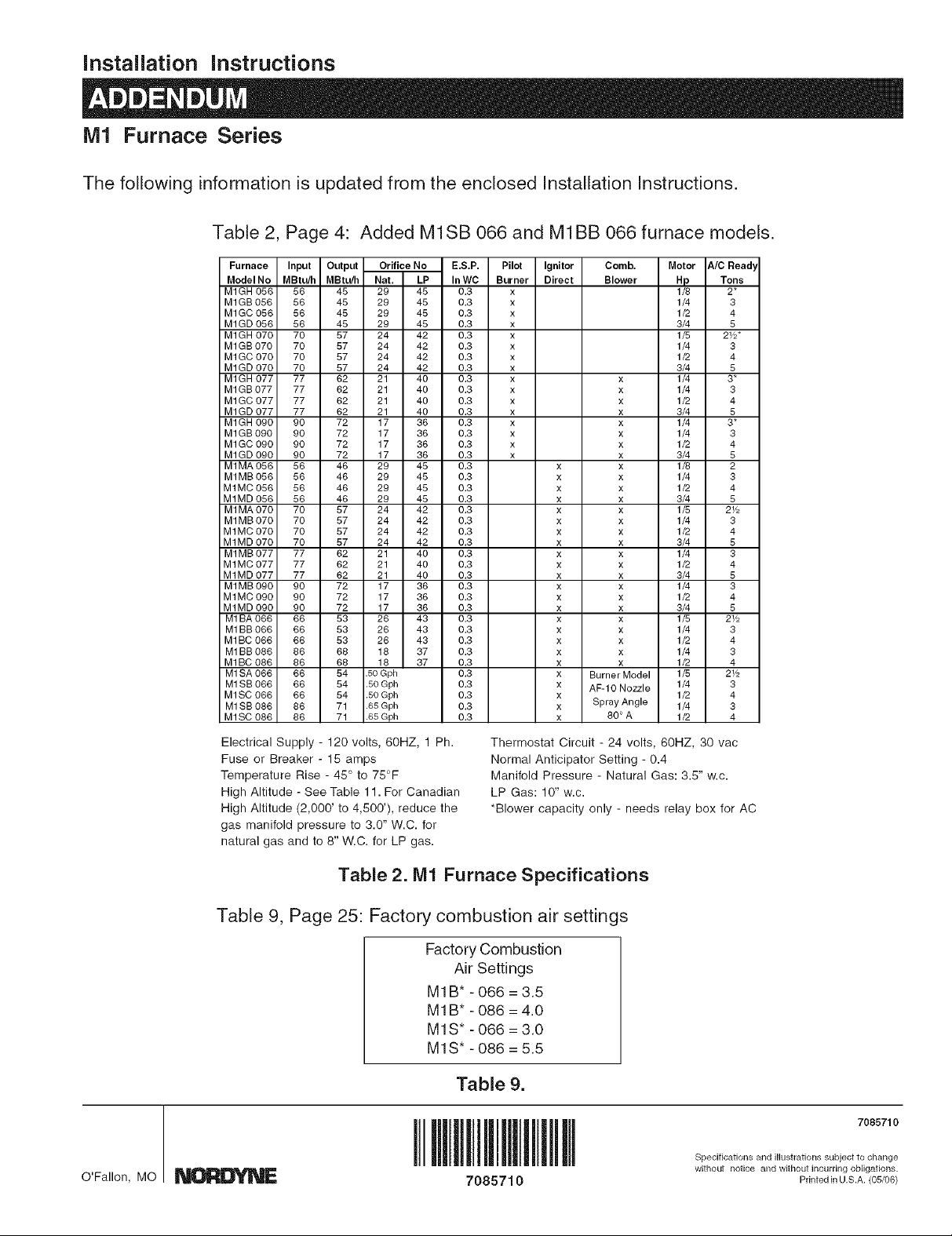
Table 2, Page 4: Added M1SB 066 and M1BB066 furnace models.
Furnace Input Output Orifice No E.S.P. Pilot Ignitor Comb. Motor _./C Bead
ModeINo MBtu/h MBtu/h Nat. LP In WC Burner Direct Blower Hp Tons
M1GH 056 56 45 29 45 0.3 x 1/8 2*
M1GB 056 56 45 29 45 0.3 x 1/4 3
M1GC 056 56 45 29 45 0.3 x 1/2 4
M1GD 056 56 45 29 45 0.3 x 3/4 5
M1GH 070 70 57 24 42 0.3 x 1/5 2V2"
M1GB 070 70 57 24 42 0.3 x 1/4 3
M1GC 070 70 57 24 42 0.3 x 1/2 4
M1GD 070 70 57 24 42 0.3 x 3/4 5
M1GH 077 77 62 21 40 0.3 x x 1/4 3*
M1GB 077 77 62 21 40 0.3 x x 1/4 3
M1GC 077 77 62 21 40 0.3 x x 1/2 4
M1GD 077 77 62 21 40 0.3 x x 3/4 5
M1GH 090 90 72 17 36 0.3 x x 1/4 3*
M1GB 090 90 72 17 36 0.3 x x 1/4 3
M1GC 090 90 72 17 36 0.3 x x 1/2 4
M1GD 090 90 72 17 36 0.3 x x 3/4 5
M1MA 056 56 46 29 45 0.3 x x 1/8 2
M1MB 056 56 46 29 45 0.3 x x 1/4 3
M1MC 056 56 46 29 45 0.3 x x 1/2 4
M1MD 056 56 46 29 45 0.3 x x 3/4 5
M1MA 070 70 57 24 42 0.3 x x 1/5 2V2
M1MB 070 70 57 24 42 0.3 x x 1/4 3
M 1MC 070 70 57 24 42 0.3 x x 1/2 4
M1MD 070 70 57 24 42 0.3 x x 3/4 5
M1MB 077 77 62 21 40 0.3 x x 1/4 3
M1MC 077 77 62 21 40 0.3 x x 1/2 4
M1MD 077 77 62 21 40 0.3 x x 3/4 5
M1MB 090 90 72 17 36 0.3 x x 1/4 3
M1MC 090 90 72 17 36 0.3 x x 1/2 4
M 1MD 090 90 72 17 36 0.3 x x 3/4 5
M1BA 066 66 53 26 43 0.3 x x 1/5 2V2
M1BB 066 66 53 26 43 0.3 x x 1/4 3
M1BC 066 66 53 26 43 0.3 x x 1/2 4
M1BB 086 86 68 18 37 0.3 x x 1/4 3
M1BC 086 86 68 18 37 0.3 x x 1/2 4
M1SA 066 66 54 .50 Gph 0.3 x Burner Model 1/5 2V2
M1SB 066 66 54 .50 Gph 0.3 x AF-IO Nozzle 1/4 3
M1SC 066 66 54 .50 Gph 0.3 x 1/2 4
M1SB 086 86 71 .65 Gph 0.3 x Spray Angle 1/4 3
M1SC 086 86 71 .65 Gph 0.3 x 80 ° A 1/2 4
Electrical Supply- 120 volts, 60HZ, 1 Ph.
Fuse or Breaker - 15 amps
Temperature Rise - 45 ° to 75°F
High Altitude - See Table 11. For Canadian
High Altitude (2,000' to 4,500'), reduce the
gas manifold pressure to 3.0" W.C. for
natural gas and to 8" W.C. for LP gas.
Thermostat Circuit - 24 volts, 60HZ, 30 vac
Normal Anticipator Setting - 0.4
Manifold Pressure - Natural Gas: 3.5" w.c.
LP Gas: 10" w.c.
*Blower capacity only - needs relay box for AC
Table 2. IVll Furnace Specifications
Table 9, Page 25: Factory combustion air settings
Factory Combustion
Air Settings
M1B* -066 = 3.5
M1B* -086 = 4.0
M1S* -066 = 3.0
MlS* - 086 = 5.5
Table 9.
7085710
Specifications and illustrations subject to change
O'Fallon, MO __ 708571 0 Pdnted inU.S.A. (05/06)
without notice and without incurring oHigations.
 Loading...