


Residential Gas Furnaces
Installation Instructions
G6RC Series 90+ Upflow Condensing Furnace G6RD Series 93+ Upflow Condensing Furnace G6RL Series 90+ Downflow Condensing Furnace
G6RC 90+, G6RD 93+ Upflow |
G6RL 90+ Downflow |
! WARNING:
Improper installation, adjustment, alteration, service, or maintenance can cause injury or property damage. Refer to this manual for assistance. For additional information consult a qualified installer, service agency, or the gas supplier.
! FOR YOUR SAFETY:
Do not store or use gasoline or other flammable vapors and liquids in the vicinity of this or any other appliance.
! FOR YOUR SAFETY:
These instructions are primarily intended to assist qualified individuals experienced in the proper installation of this appliance. Some local codes require licensed installation/service personnel for this type of equipment. Read all instructions carefully before starting the installation.
DO NOT DESTROY. PLEASE READ CAREFULLY AND KEEP IN A SAFE PLACE FOR FUTURE REFERENCE.
WHAT TO DO IF YOU SMELL GAS:
•Do not try to light any appliance.
•Do not touch any electrical switch; do not use any phone in your building.
•Immediately call your gas supplier from a neighbor's phone. Follow the gas supplier's instructions.
•If you cannot reach your gas supplier, call the fire department.
•Extinguish any open flame.
Table of Contents |
|
Furnace Specifications ............................................................................................................ |
4-5 |
Furnace Airflow Data .......................................................................................................... |
6-7 |
Installation Requirements .......................................................................................................... |
8 |
Supply Air Plenum Installation .................................................................................................. |
9 |
Installation on a Concrete Slab ............................................................................................. |
9 |
Installation on a Combustible Floor ....................................................................................... |
9 |
Circulating Air Supply ............................................................................................................... |
10 |
Return Air ............................................................................................................................ |
11 |
Venting and Combustion Air Requirements .......................................................................... |
11 |
Air Requirements for One-Pipe Installation ........................................................................ |
13 |
Installation in An Unconfined Space ................................................................................... |
13 |
Installation in A Confined Space ......................................................................................... |
13 |
• Air From Inside .................................................................................................................. |
13 |
• Air Directly Through An Exterior Wall ............................................................................... |
14 |
• Outdoor Air Through Vertical Openings or Ducts ............................................................. |
14 |
• Outdoor Air Through Horizontal Openings or Ducts ......................................................... |
14 |
Venting Requirements .............................................................................................................. |
14 |
Vent Pipe Material ............................................................................................................... |
14 |
Vent Pipe Length and Diameter .......................................................................................... |
14 |
Vent Pipe Installation .......................................................................................................... |
15 |
Pipe Routing & Support ....................................................................................................... |
15 |
Location of Outdoor Terminations ....................................................................................... |
18 |
Horizontal Venting ............................................................................................................... |
19 |
Vertical Venting ................................................................................................................... |
20 |
Vent Freezing Protection ..................................................................................................... |
20 |
Concentric Vent Termination ............................................................................................... |
20 |
Drainage of Condensate From Furnace ................................................................................. |
21 |
Gas Supply and Piping ........................................................................................................ |
22 |
Leak Check .......................................................................................................................... |
22 |
Conversion ........................................................................................................................... |
23 |
High Altitude Application ..................................................................................................... |
23 |
Natural Gas High Altitude Conversion ................................................................................ |
23 |
LP/Propane Gas Sea Level and High Altitude Conversion ................................................ |
23 |
Electrical Wiring ........................................................................................................................ |
24 |
Line Voltage Wiring ............................................................................................................. |
24 |
Low Voltage Wiring ............................................................................................................. |
25 |
Start-up and Adjustments ......................................................................................................... |
25 |
Start-Up Procedure .............................................................................................................. |
26 |
Verifying and Adjusting Firing Rate ..................................................................................... |
26 |
Verifying and Adjusting Temperature Rise ......................................................................... |
27 |
Verifying Burner Operation .................................................................................................. |
27 |
Verifying Operation of the Supply Air Limit Switch ............................................................. |
29 |
Description of Components ..................................................................................................... |
29 |
Maintenance ............................................................................................................................... |
31 |
Combustion Air and Vent System ....................................................................................... |
31 |
Air Filter(s) ........................................................................................................................... |
31 |
Lubrication ........................................................................................................................... |
31 |
Condensate Drain Assembly ............................................................................................... |
31 |
Blower Compartment ........................................................................................................... |
31 |
Heat Exchanger and Burner Maintenance .......................................................................... |
31 |
Location of Major Components ........................................................................................... |
32 |
System Operation Information ................................................................................................. |
31 |
Sequence of Operation ....................................................................................................... |
33 |
Furnace Fails to Operate .................................................................................................... |
34 |
Twinning of Two Furnaces .................................................................................................. |
34 |
Installation/Performance Checklist ......................................................................................... |
35 |

4
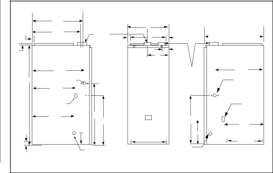
Dimensions Unit G6RD G6RC, .1 Figure
Upflow G6RC & G6RD Furnaces
3/4" 3/4"
43"
15"
1"
Combustion Air
Inlet 23 1/4"
Exhaust Vent
 22 1/2"


 19 3/4"
25 1/8"
1 1/2" x 3 1/2" Dia.
Opening for
Gas Connection
7/8" Dia. Electric
Connection
+
Combustion Air Vent
(See Fig. 15 3/4"
 for sizes)
25 1/4" |
33" |
|
20 1/2"
8" Return Air Opening
(Side)
1 1/4" |
|
|
23" |
|
|||
|
|
|
|
28"
A
B
C |
2 1/4" |
3/4"


 2" PVC Exhaust Vent
(See Fig. 15 for sizes)
30 1/4"

25 1/4"
Return Air Opening (Bottom)
D
Condensate Drain Outlets
27 5/8"
1 1/2" x 3 1/2" Dia. Opening for
Gas Connection 7/8" Dia. Electric
+Connection
25 5/8"
8"
23"  Bottom Return Opening
SPECIFICATIONS FURNACE
|
Downflow G6RL Furnace |
|
|
|
|
|
|
|
|
Combustion Air Inlet |
|
|
|
|
|
|
|
24 1/2" |
|
|
|
|
|
|
|
Exhaust Vent |
|
|
A |
|
|
|
3/4" |
22 1/2" |
Exhaust |
|
|
|
|
|
|
|
B |
|
27 7/8" |
||
|
|
|
Vent |
3/4" |
3/4" |
||
|
|
|
|
||||
|
|
|
2" |
|
|
|
|
|
3/4" |
|
|
|
|
2 1/2" |
|
Figure |
|
|
|
|
C |
|
|
|
|
|
|
C |
|
|
|
|
|
|
|
L |
|
|
|
|
24 7/8" |
|
|
|
Combusting |
24 7/8" |
|
2 |
|
|
|
|
|||
|
|
|
|
Vent |
|||
. |
|
|
|
|
|
|
|
G6RL |
|
7/8" Dia. Electric |
|
|
|
|
|
43" |
|
|
|
(3" for 80/100 |
7/8" Dia. |
||
Connection |
|
|
|
2" for 40/60) |
|||
|
|
|
|
|
Electric |
||
|
|
|
|
|
|
Connection |
|
Unit |
|
21 7/8" |
|
|
|
|
|
|
|
|
|
|
|
||
|
1 1/2" x 3 1/2" Dia. |
|
|
|
|
|
|
Dimensions |
|
|
|
|
|
|
|
|
Opening for |
|
|
|
|
1 1/2" x 2 1/2" |
|
|
Gas Connection |
|
|
|
|
Knockout |
|
|
|
|
|
|
|
For Gas |
|
|
|
|
|
|
|
Connection |
|
|
21 1/4" |
21 1/2" |
|
|
21 1/2" |
|
|
|
|
|
15 1/2" |
|
|
21 7/8" |
|
|
|
|
|
|
|
|
|
|
|
8" |
|
|
Bottom Supply Air Opening |
10 1/4" |
|
|
|
|
|
|
|
|
|
|
|
|
|
|
(Side) |
|
19 3/4" |
|
1" |
|
|
|
D |
|
|
|
|
|
|
|
Condensate |
|
|
|
|
|
Condensate |
|
|
Bottom Opening |
|
|
|
|
|
|
Drain |
|
|
|
|
|
Drain |
|
|
Outlet |
|
|
|
|
Outlet |
|
|
|
|
5 |
|
|
|
|
|
|
|

6
|
|
Heating |
|
|
|
|
|
|
|
|
|
|
External Static Pressure (Inches Water Column) |
|
|
|
|
|
|
|
|
|||||||||
|
Model |
Input |
Motor |
Motor |
0.1 |
|
0.2 |
|
0.3 |
0.4 |
|
0.5 |
|
0.6 |
|
0.7 |
|
|
0.8 |
|
||||||||||
|
Number |
(Btuh) |
High* |
HP |
1310 |
|
- |
1260 |
|
- |
1210 |
|
- |
1160 |
|
45 |
1100 |
|
47 |
1040 |
|
50 |
980 |
|
53 |
920 |
|
56 |
CAPACITIES |
|
|
Speed |
|
CFM |
|
Rise |
CFM |
|
Rise |
CFM |
|
Rise |
CFM |
|
Rise |
CFM |
|
Rise |
CFM |
|
Rise |
CFM |
|
Rise |
CFM |
|
Rise |
|
|||
|
|
|
High* |
|
|
950 |
|
36 |
920 |
|
38 |
890 |
|
39 |
850 |
|
41 |
800 |
|
43 |
750 |
|
46 |
690 |
|
50 |
630 |
|
55 |
|
|
G6RC040C-08 |
40,000 |
Medium |
1/5 |
740 |
|
47 |
710 |
|
49 |
680 |
|
51 |
650 |
|
53 |
600 |
|
58 |
550 |
|
63 |
490 |
|
- |
430 |
|
- |
|
|
|
|
|
Low** |
|
620 |
|
56 |
590 |
|
59 |
560 |
|
62 |
520 |
|
- |
470 |
|
- |
410 |
|
- |
350 |
|
- |
290 |
|
- |
|
|
|
|
|
High* |
|
|
1330 |
|
- |
1280 |
|
- |
1230 |
|
- |
1170 |
|
- |
1120 |
|
- |
1030 |
|
- |
940 |
|
37 |
850 |
|
41 |
|
|
G6RC040C-12 |
40,000 |
Medium |
1/3 |
1190 |
|
- |
1160 |
|
- |
1110 |
|
- |
1060 |
|
- |
1010 |
|
- |
910 |
|
38 |
820 |
|
42 |
720 |
|
48 |
|
|
|
|
|
Low** |
|
830 |
|
42 |
810 |
|
43 |
780 |
|
44 |
760 |
|
46 |
720 |
|
48 |
670 |
|
52 |
610 |
|
57 |
550 |
|
63 |
|
|
|
G6RC060C-12 |
60,000 |
Medium |
1/3 |
1160 |
|
45 |
1120 |
|
46 |
1080 |
|
48 |
1050 |
|
49 |
990 |
|
52 |
940 |
|
55 |
890 |
|
58 |
830 |
|
63 |
— |
|
AirflowFurnace.1 Table |
|
|
|
|
|
|
|
|
DataAirflowFurnace |
|||||||||||||||||||||
|
|
Med-Low |
|
1440 |
|
72 |
1410 |
|
74 |
1380 |
|
75 |
1320 |
|
79 |
1280 |
|
81 |
1220 |
|
85 |
1150 |
|
- |
1080 |
|
- |
|||
|
|
|
Low** |
|
800 |
|
65 |
780 |
|
67 |
760 |
|
68 |
740 |
|
70 |
710 |
|
73 |
680 |
|
- |
650 |
|
- |
620 |
|
- |
|
|
|
|
|
High* |
|
|
1490 |
|
46 |
1450 |
|
48 |
1390 |
|
50 |
1310 |
|
53 |
1210 |
|
57 |
1100 |
|
63 |
980 |
|
- |
830 |
|
- |
|
|
G6RC080C-12 |
80,000 |
Medium |
1/3 |
1230 |
|
56 |
1200 |
|
58 |
1150 |
|
60 |
1080 |
|
64 |
1010 |
|
69 |
910 |
|
- |
810 |
|
- |
680 |
|
- |
|
|
|
|
|
Low** |
|
780 |
|
- |
750 |
|
- |
720 |
|
- |
680 |
|
- |
630 |
|
- |
570 |
|
- |
510 |
|
- |
440 |
|
- |
|
|
|
|
|
High* |
|
1840 |
|
- |
1780 |
|
- |
1700 |
|
41 |
1630 |
|
42 |
1550 |
|
45 |
1470 |
|
47 |
1380 |
|
50 |
1290 |
|
54 |
|
|
|
G6RC080C-16 |
80,000 |
Med-High |
1/2 |
1600 |
|
43 |
1560 |
|
44 |
1470 |
|
47 |
1400 |
|
49 |
1350 |
|
51 |
1280 |
|
54 |
1210 |
|
57 |
1150 |
|
60 |
|
|
|
|
|
Med-Low** |
|
1380 |
|
50 |
1350 |
|
51 |
1300 |
|
53 |
1250 |
|
55 |
1190 |
|
58 |
1120 |
|
62 |
1040 |
|
67 |
960 |
|
- |
|
|
|
|
|
Low |
|
1100 |
|
- |
1050 |
|
- |
1000 |
|
- |
950 |
|
- |
900 |
|
- |
850 |
|
- |
800 |
|
- |
750 |
|
- |
|
|
|
|
|
High* |
|
1910 |
|
45 |
1860 |
|
47 |
1780 |
|
49 |
1700 |
|
51 |
1620 |
|
53 |
1520 |
|
57 |
1420 |
|
61 |
1310 |
|
66 |
|
|
|
G6RC100C-16 |
100,000 |
Med-High** |
1/2 |
1640 |
|
53 |
1620 |
|
53 |
1540 |
|
56 |
1480 |
|
58 |
1420 |
|
61 |
1340 |
|
65 |
1250 |
|
69 |
1150 |
|
75 |
|
|
|
|
|
Med-Low |
|
1440 |
|
60 |
1410 |
|
61 |
1370 |
|
63 |
1320 |
|
66 |
1270 |
|
68 |
1210 |
|
72 |
1140 |
|
- |
1060 |
|
- |
|
|
|
|
|
Low |
|
1230 |
|
- |
1210 |
|
- |
1180 |
|
- |
1140 |
|
- |
1090 |
|
- |
1030 |
|
- |
960 |
|
- |
880 |
|
- |
|
|
|
|
|
High* |
|
1860 |
|
56 |
1800 |
|
58 |
1730 |
|
60 |
1650 |
|
63 |
1570 |
|
66 |
1480 |
|
70 |
1380 |
|
75 |
1270 |
|
82 |
|
|
|
G6RC120C-16 |
120,000 |
Med-High** |
1/2 |
1650 |
|
63 |
1610 |
|
65 |
1550 |
|
67 |
1480 |
|
70 |
1410 |
|
74 |
1320 |
|
79 |
1230 |
|
84 |
1120 |
|
- |
|
|
Data |
|
|
Low |
|
1230 |
|
- |
1210 |
|
- |
1180 |
|
- |
1140 |
|
- |
1090 |
|
- |
1030 |
|
- |
960 |
|
- |
880 |
|
- |
|
|
|
|
High* |
|
2260 |
|
- |
2200 |
|
- |
2140 |
|
- |
2070 |
|
- |
1990 |
|
- |
1910 |
|
- |
1810 |
|
57 |
1710 |
|
61 |
|
||
|
|
|
|
|
|
|
|
|
|
|
|
|
||||||||||||||||||
|
G6RC120C-20 |
120,000 |
Med-High |
3/4 |
1870 |
|
56 |
1840 |
|
56 |
1790 |
|
58 |
1760 |
|
59 |
1710 |
|
61 |
1660 |
|
63 |
1610 |
|
65 |
1560 |
|
67 |
|
|
|
|
|
Med-Low** |
|
1540 |
|
67 |
1530 |
|
68 |
1510 |
|
69 |
1470 |
|
71 |
1430 |
|
73 |
1370 |
|
76 |
1300 |
|
80 |
1220 |
|
85 |
|
|
|
|
|
Low |
|
1360 |
|
- |
1330 |
|
- |
1310 |
|
- |
1280 |
|
- |
1250 |
|
- |
1220 |
|
- |
1190 |
|
- |
1150 |
|
- |
|
|
|
|
|
High* |
|
1050 |
|
- |
1005 |
|
- |
960 |
|
- |
915 |
|
- |
855 |
|
- |
800 |
|
- |
730 |
|
48 |
670 |
|
53 |
|
|
|
G6RD040C-10 |
40,000 |
Medium |
1/3 |
990 |
|
- |
950 |
|
- |
905 |
|
- |
860 |
|
- |
810 |
|
- |
760 |
|
46 |
700 |
|
50 |
650 |
|
54 |
|
|
|
|
|
Low** |
|
770 |
|
46 |
740 |
|
48 |
700 |
|
50 |
660 |
|
53 |
625 |
|
56 |
580 |
|
61 |
540 |
|
65 |
500 |
|
70 |
|
|
|
|
|
High* |
|
1175 |
|
45 |
1125 |
|
47 |
1075 |
|
49 |
1030 |
|
51 |
970 |
|
54 |
920 |
|
57 |
860 |
|
61 |
800 |
|
66 |
|
|
|
G6RD060C-10 |
60,000 |
Medium** |
1/3 |
1075 |
|
49 |
1040 |
|
51 |
995 |
|
53 |
950 |
|
56 |
900 |
|
59 |
840 |
|
63 |
790 |
|
67 |
720 |
|
73 |
|
|
|
|
|
Low |
|
800 |
|
66 |
770 |
|
69 |
745 |
|
71 |
710 |
|
74 |
670 |
|
- |
630 |
|
- |
580 |
|
- |
530 |
|
- |
|
|

Data Airflow Furnace .2 Table
|
Heating |
|
|
|
|
|
|
|
|
|
External Static Pressure (Inches Water Column) |
|
|
|
|
|
|
|
|||||||||
Model |
Input |
Motor |
Motor |
|
0.1 |
0.2 |
|
0.3 |
0.4 |
|
0.5 |
|
0.6 |
|
0.7 |
|
|
0.8 |
|||||||||
Number |
(Btuh) |
Speed |
HP |
CFM |
|
Rise |
CFM |
|
Rise |
CFM |
|
Rise |
CFM |
|
Rise |
CFM |
|
Rise |
CFM |
|
Rise |
CFM |
|
Rise |
CFM |
|
Rise |
|
|
High* |
|
1620 |
|
- |
1560 |
|
45 |
1490 |
|
47 |
1430 |
|
49 |
1365 |
|
52 |
1300 |
|
54 |
1240 |
|
57 |
1170 |
|
60 |
G6RD080C-14 |
80,000 |
Med-High |
1/2 |
1450 |
|
49 |
1400 |
|
50 |
1350 |
|
52 |
1295 |
|
54 |
1240 |
|
57 |
1180 |
|
60 |
1120 |
|
63 |
1060 |
|
66 |
|
|
Med-Low** |
|
1255 |
|
56 |
1225 |
|
57 |
1180 |
|
60 |
1145 |
|
61 |
1105 |
|
64 |
1060 |
|
66 |
1020 |
|
69 |
980 |
|
72 |
|
|
Low |
|
1080 |
|
65 |
1055 |
|
67 |
1030 |
|
68 |
1000 |
|
70 |
960 |
|
73 |
920 |
|
- |
870 |
|
- |
820 |
|
- |
|
|
High* |
|
1620 |
|
54 |
1555 |
|
57 |
1485 |
|
59 |
1425 |
|
62 |
1355 |
|
65 |
1290 |
|
68 |
1220 |
|
72 |
1160 |
|
- |
G6RD100C-14 |
100,000 |
Med-High** |
1/2 |
1430 |
|
62 |
1375 |
|
64 |
1330 |
|
66 |
1265 |
|
70 |
1210 |
|
73 |
1150 |
|
- |
1080 |
|
- |
1010 |
|
- |
|
|
Med-Low |
|
1260 |
|
70 |
1220 |
|
72 |
1170 |
|
75 |
1130 |
|
- |
1070 |
|
- |
1010 |
|
- |
950 |
|
- |
890 |
|
- |
|
|
Low |
|
1085 |
|
- |
1050 |
|
- |
1015 |
|
- |
970 |
|
- |
935 |
|
- |
890 |
|
- |
850 |
|
- |
800 |
|
- |
|
|
High* |
|
1700 |
|
62 |
1635 |
|
65 |
1565 |
|
67 |
1500 |
|
70 |
1435 |
|
74 |
1370 |
|
77 |
1310 |
|
- |
1240 |
|
- |
G6RD120C-14 |
120,000 |
Med-High** |
1/2 |
1510 |
|
70 |
1455 |
|
73 |
1405 |
|
75 |
1350 |
|
78 |
1290 |
|
- |
1230 |
|
- |
1170 |
|
- |
1100 |
|
- |
|
|
Med-Low |
|
1330 |
|
79 |
1280 |
|
- |
1240 |
|
- |
1195 |
|
- |
1145 |
|
- |
1100 |
|
- |
1050 |
|
- |
1000 |
|
- |
|
|
Low |
|
1140 |
|
- |
1110 |
|
- |
1075 |
|
- |
1040 |
|
- |
1010 |
|
- |
980 |
|
- |
940 |
|
- |
910 |
|
- |
|
|
High* |
|
2140 |
|
- |
2070 |
|
- |
2010 |
|
- |
1945 |
|
- |
1870 |
|
56 |
1800 |
|
59 |
1730 |
|
61 |
1650 |
|
64 |
G6RD120C-19 |
120,000 |
Med-High |
3/4 |
1955 |
|
- |
1900 |
|
56 |
1850 |
|
57 |
1800 |
|
59 |
1740 |
|
61 |
1690 |
|
62 |
1630 |
|
65 |
1570 |
|
67 |
|
|
Med-Low** |
|
1660 |
|
64 |
1620 |
|
65 |
1575 |
|
67 |
1540 |
|
69 |
1495 |
|
71 |
1460 |
|
72 |
1410 |
|
75 |
1370 |
|
77 |
|
|
Low |
|
1450 |
|
73 |
1430 |
|
74 |
1400 |
|
75 |
1360 |
|
78 |
1340 |
|
79 |
1300 |
|
81 |
1270 |
|
83 |
1230 |
|
- |
|
|
High* |
|
1280 |
|
- |
1210 |
|
- |
1180 |
|
- |
1140 |
|
- |
1090 |
|
- |
1070 |
|
- |
1030 |
|
- |
990 |
|
- |
G6RL040C-12 |
40,000 |
Medium |
1/3 |
1140 |
|
- |
1090 |
|
- |
1060 |
|
- |
1030 |
|
- |
980 |
|
35 |
950 |
|
36 |
910 |
|
37 |
870 |
|
39 |
|
|
Low** |
|
875 |
|
39 |
835 |
|
41 |
820 |
|
41 |
805 |
|
42 |
780 |
|
43 |
770 |
|
44 |
760 |
|
45 |
750 |
|
45 |
|
|
High* |
|
1260 |
|
40 |
1190 |
|
43 |
1155 |
|
44 |
1120 |
|
45 |
1075 |
|
47 |
1030 |
|
49 |
980 |
|
52 |
940 |
|
54 |
G6RL060C-12 |
60,000 |
Medium |
1/3 |
1120 |
|
45 |
1070 |
|
48 |
1040 |
|
49 |
1010 |
|
50 |
960 |
|
53 |
930 |
|
55 |
890 |
|
57 |
850 |
|
60 |
|
|
Low** |
|
855 |
|
59 |
815 |
|
62 |
800 |
|
64 |
780 |
|
65 |
760 |
|
67 |
730 |
|
70 |
710 |
|
- |
690 |
|
- |
|
|
High* |
|
1635 |
|
- |
1585 |
|
- |
1525 |
|
- |
1460 |
|
46 |
1400 |
|
48 |
1330 |
|
51 |
1260 |
|
54 |
1180 |
|
57 |
G6RL080C-16 |
80,000 |
Med-High |
1/2 |
1435 |
|
47 |
1395 |
|
49 |
1350 |
|
50 |
1300 |
|
52 |
1255 |
|
54 |
1200 |
|
56 |
1150 |
|
59 |
1090 |
|
62 |
|
|
Med-Low** |
|
1230 |
|
55 |
1200 |
|
56 |
1165 |
|
58 |
1130 |
|
60 |
1090 |
|
62 |
1050 |
|
65 |
1000 |
|
68 |
960 |
|
71 |
|
|
Low |
|
1050 |
|
- |
1035 |
|
- |
1010 |
|
- |
980 |
|
- |
950 |
|
- |
910 |
|
- |
870 |
|
- |
820 |
|
- |
|
|
High* |
|
1600 |
|
53 |
1555 |
|
54 |
1500 |
|
56 |
1445 |
|
59 |
1380 |
|
61 |
1310 |
|
65 |
1240 |
|
68 |
1160 |
|
73 |
G6RL100C-16 |
100,000 |
Med-High** |
1/2 |
1475 |
|
57 |
1435 |
|
59 |
1385 |
|
61 |
1335 |
|
63 |
1290 |
|
66 |
1240 |
|
68 |
1190 |
|
71 |
1130 |
|
75 |
|
|
Med-Low |
|
1320 |
|
- |
1290 |
|
- |
1250 |
|
- |
1215 |
|
- |
1170 |
|
- |
1120 |
|
- |
1070 |
|
- |
1020 |
|
- |
|
|
Low |
|
1150 |
|
- |
1130 |
|
- |
1110 |
|
- |
1075 |
|
- |
1040 |
|
- |
1000 |
|
- |
950 |
|
- |
890 |
|
- |
** Factory Set Cooling Speed |
NOTES: 1. Airflow rates of 1800 CFM or more require two return air connections. Data is for operation with filter(s). |
|
** Factory Set Heating Speed |
2. |
Temperature rises in the table are approximate. Actual temperature rises may vary. |
- Not Recommended |
3. |
Temperature rises and airflows for external static pressures greater than 0.5 are for reference only. |
|
|
These conditions are not recommended. |
7
INSTALLATION REQUIREMENTS
Requirements and Codes
This furnace must be installed in accordance with these instructions, all applicable local building codes, and the current revision of the National Fuel Gas Code (ANSI-Z223.1, NFPA-54). The current revision of the National Fuel Gas Code is available from:
American National Standards Institute, Inc. 1430 Broadway
New York, New York 10018
Canada installations shall comply with CAN/ CGA-B149 installation codes, local plumbing or waste water codes and other applicable codes. Additional helpful publications are:
•NFPA-90A - Installation of Air Conditioning and Ventilating Systems.
•NFPA-90B - Warm Air Heating and Air Conditioning Systems.
These publications are available from: National Fire Protection Association, Inc. Batterymarch Park
Quincy, Massachusetts 02269
! WARNING:
This furnace is not approved for installation in mobile homes. Installation in a mobile home could cause fire, property damage, and/or personal injury.
Model |
Furnace |
|
Dimensions (inches) |
|
Shipping |
||
Number |
Btuh |
|
|
|
|
Weight |
|
A |
B |
C |
D |
||||
(lbs) |
|||||||
|
|
||||||
|
|
|
|
|
|
||
G6R(C,D)040C |
40,000 |
14 1/4 |
12 3/4 |
5 1/8 |
11 3/4 |
133 |
|
G6R(C,D)060C |
60,000 |
14 1/4 |
12 3/4 |
5 1/8 |
11 3/4 |
140 |
|
G6R(C,D)080C |
80,000 |
19 3/4 |
18 1/4 |
7 7/8 |
17 1/4 |
172 |
|
G6R(C,D)100C |
100,000 |
19 3/4 |
18 1/4 |
7 7/8 |
17 1/4 |
180 |
|
G6R(C,D)120C |
120,000 |
22 1/2 |
21 |
9 1/4 |
20 |
204 |
|
G6RL040C |
40,000 |
14 1/4 |
12 3/4 |
4 5/8 |
12 3/4 |
135 |
|
G6RL060C |
60,000 |
14 1/4 |
12 3/4 |
4 5/8 |
12 3/4 |
135 |
|
G6RL080C |
80,000 |
19 3/4 |
18 1/4 |
10 |
18 1/4 |
174 |
|
G6RL100C |
100,000 |
19 3/4 |
18 1/4 |
10 |
18 1/4 |
185 |
|
Table 3. Furnace Dimensions and Shipping Weights
CLEARANCES TO COMBUSTIBLE MATERIALS
This furnace is Designed Certified by AGA/CGA Laboratories for the minimum clearances to combustible material listed in Table 4. See the furnace name plate, located inside the furnace cabinet, for specific model number and clearance information.
MINIMUM CLEARANCES TO COMBUSTIBLE MATERIAL
|
Furnace |
Cabinet |
|
Minimum Clearances (Inches) |
|
||
|
Input |
Width |
|
|
|
|
|
|
(Btuh) |
(Inches) |
Side |
Vent |
Back |
Top |
Front |
40,000 |
14 1/4 |
0 |
0 |
0 |
1 |
1* |
|
60,000 |
14 1/4 |
0 |
0 |
0 |
1 |
1* |
|
80,000 |
14 1/4 |
0 |
0 |
0 |
1 |
1* |
|
100,000 |
19 3/4 |
0 |
0 |
0 |
1 |
1* |
|
120,000 |
22 1/2 |
0 |
0 |
0 |
1 |
1* |
|
* 24 inches is the minimum clearance for servicing.
36 inches is the recommended clearance for service.
Table 4. Minimum Clearances to Combustible Materials
8
Location
The furnace must be installed on a level surface, and as close to the center of the air distribution system as possible. See Table 3 for overall dimensions to determine the required clearances in hallways, doorways, stairs, etc. to allow the furnace to be moved to the installation point. The furnace must be installed so that all electrical components are protected from water.
Minimum clearances to combustible materials are listed in Table 4. Access for positioning and servicing must be considered when locating the unit. 24 inches is the minimum required clearance for servicing the unit. 30 inches is the minimum required clearance for positioning the unit. 36 inches is the recommended clearance from the front of the unit. Please note that a panel or door can be located such that the minimum clearance on the rating plate is satisfied, but that panel or door must be removable and allow the appropriate clearance for your installation.
This furnace is certified for use on wood flooring. The furnace must be installed on a solid surface and must be level front to back and side to side. This furnace must not be installed directly on carpeting, tile, or any combustible material other than wood flooring.
DOWNFLOW WARNING
(G6RL Models):
The design of the downflow furnace is certified for natural or propane gas and for installation on non-combustible flooring. A special combustible floor sub-base is required when installing on a combustible floor. Failure to install the subbase may result in fire, property damage and personal injury. The special downflow sub-bases are factory supplied accessories, part numbers 902677 and 902974. When the furnace is installed on a factory or site-built cased air conditioning coil, the sub-base is not necessary. However, the plenum attached to the coil casing must be installed such that its surfaces are at least 1" from combustible construction.
A gas-fired furnace installed in a residential garage must be installed so that the bottom of the furnace is located a minimum of 15" from the floor. The furnace must be located or protected to avoid physical damage by vehicles.
HORIZONTAL INSTALLATIONS
The G6RC model furnaces are approved for horizontal installation. Installation Kit #903568 is required for horizontal applications. Follow the installation instructions in the kit for proper conversion. NOTE: The G6RD and G6RL models are NOT approved for horizontal installation.
SUPPLY AIR PLENUM INSTALLATION
A.Installation on a concrete slab - G6RL
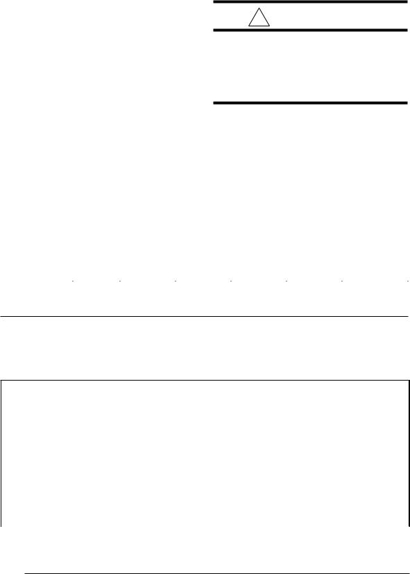
1.Construct a hole in the floor per the dimensions in Figure 3.
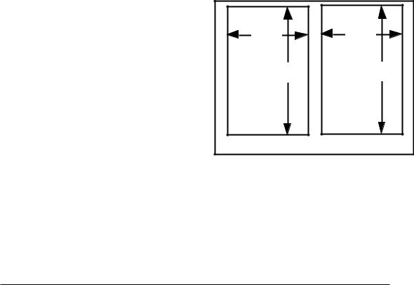
2.Place the plenum and the furnace as shown in Figure 4.
B.Installation on a combustible floor - G6RL
1.Cut and frame the hole in the floor per the dimensions in Figure 5.
2.Place the sub-base for combustible floors over the hole with its duct collar extended downward. Attach the supply air plenum to the base in a manner which will ensure 1" clearancetotheflooringorothercombustible material. Place furnace on the combustible base as shown in Figure 6.
3.When the furnace is installed on a factory or site-built cased air conditioning coil, the sub-base is not necessary. However, the plenum attached to the coil casing must be installed such that its surfaces are at least 1" from combustible material.
18.75" |
13.25" |
19.25" |
19.25" |
Hole in |
Hole in |
Floor |
Floor |
G6RL 080/100 |
G6RL 040/060 |
Figure 3. Opening for Concrete Slab
9
Concrete |
Furnace |
Floor |
|
|
Sheet |
|
Metal |
|
Plenum |
Figure 4. Furnace on a Concrete Slab
18.75" |
13.25" |
19.63" |
19.63" |
Hole in |
Hole in |
Floor |
Floor |
G6RL 080/100 |
G6RL 040/060 |
Figure 5. Opening in Wood Floor
Downflow |
Furnace |
Wood |
Sub-base |
Floor |
|
|
Sheet |
|
|
Metal |
|
|
Plenum |
|
Figure 6. Furnace on a Wood Floor
CIRCULATING AIR SUPPLY
Plenums and air ducts must be installed in accordance with the Standard for the Installation of Air Conditioning and Ventilating Systems (NFPA No. 90A) or the Standard for the Installation of Warm Air Heating and Air Conditioning Systems (NFPA No. 90B).
10
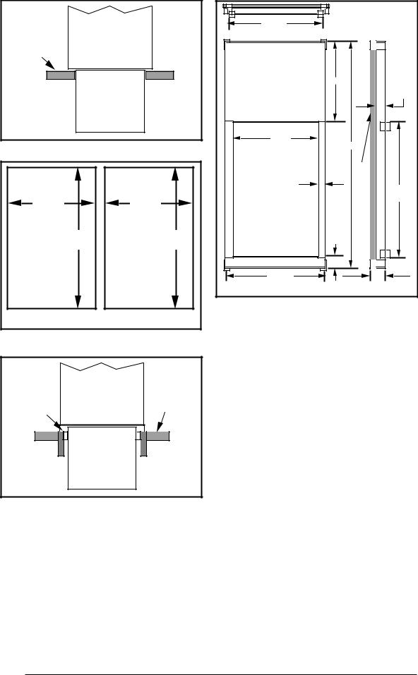
|
* Smaller |
|
||
18.75" |
dimensions for |
|||
G6RL 040/060 |
||||
or 13.25"* |
||||
|
9.25" |
|
|
|
|
|
|
2.0" |
|
16.75" |
28.38" |
3 lb density |
|
|
or 11.25"* |
|
|||
|
|
|
||
1.50" |
|
thick fiberglass |
19.63" |
|
|
|
|||
|
1.58" |
|
||
|
1 inch |
|
||
|
|
|
||
19.75" |
|
|
3" |
|
or 14.25"* |
|
|
|
|
Figure 7. Downflow Sub-Base Dimensions
If outside air is utilized as return air to the furnace for ventilation or to improve indoor air quality, the system must be designed so that the return air to the furnace is not less than 50°F (10°C) during heating operation. If a combination of indoor and outdoor air is used, the ducts and damper system must be designed so that the return air supply to the furnace is equal to the return air supply under normal, indoor return air applications.
When a cooling system is installed which uses the furnace blower to provide airflow over the indoor coil, the coil must be installed downstream (on the outlet side) or in parallel with the furnace.
If a cooling system is installed in parallel with the furnace, a damper must be installed to prevent chilled air from entering the furnace and condensing on the heat exchanger. If a manually operated damper is installed, it must be designed so that operation of the furnace is prevented when the damper is in the cooling position and operation of the cooling system is prevented when the damper is in the heating position.
! WARNING:
Products of combustion must not be allowed to enter the return air ductwork or the circulating air supply. Failure to prevent products of combustion from being circulated into the living space can create potentially hazardous conditions including carbon monoxide poisoning that could result in personal injury or death.
All return ductwork must be adequately sealed, all joints must be taped, and the ductwork must be secured to the furnace with sheet metal screws. When return air is provided through the bottom of the furnace, the joint between the furnace and the return air plenum must be sealed.
The floor or platform on which the furnace is mounted must provide sound physical support of the furnace with no gaps, cracks, or sagging between the furnace and the floor or platform.
Return air and circulating air ductwork must not be connected to any other heat producing device such as a fireplace insert, stove, etc.
Return Air
The return air ductwork may be connected to any or all of the following: left side return, right side return, or bottom return. Tables 1 and 2 show the airflow data for each furnace model.
Where maximum airflow is 1800 CFM or more two openings must be used.
VENTING AND COMBUSTION AIR REQUIREMENTS
NORDYNE condensing furnaces may be installed with outdoor combustion air piped directly to the furnace, or without such special piping. Codes refer to the former as "direct vent" or "two pipe" installation. Installation with air taken from around the furnace is sometimes referred to as "one pipe" installation - i.e. only the vent (exhaust) pipe is provided.
An important consideration in selecting one or two pipe installation is the quality of the combustion air. Indoor air is sometimes contaminated with various household chemicals which can cause severe corrosion in the furnace combustion system. Some common sources of these chemicals are detergents, bleaches, aerosol sprays, and cleaning solvents. Unless indoor air is known to be free of these materials, two pipe installation is recommended.
Provisions must be made for adequate supply of air for combustion and ventilation. For United States installations, the adequacy of air provisions can be determined by consulting the current version of the National Fuel Gas Code (ANSI Z223.1/NPFA-54). For Canadian installations, requirements are specified in the National Standard of Canada (CAN/CGA B149.1 & .2). Consult local codes for special requirements.
NOTE: If the furnace is operated without adequate air for combustion and ventilation, it may not perform properly. Furnace components may be strained by high temperature and could fail prematurely.
! WARNING:
Furnace installation using methods other than those described in the following sections must comply with the National Fuel Gas Code and all applicable local codes to provide sufficient combustion air for the furnace.
G6RC/G6RD |
Protective Screen |
G6RL |
|
Figure 8. Protective Screen for One Pipe Installations
11
 Loading...