


Downflow, Direct Vent (Sealed Combustion) Forced Air Gas and Oil Furnaces
Owners Manual/Installation Instructions
Series M1B, M1G, M1M and M1S
For installation in:
1. Manufactured Homes
2. Recreational Vehicles, Park Models, Manufactured Buildings
3. Modular Homes/Buildings
! WARNING:
If the information in this manual is not followed exactly, a fire or explosion may result causing property damage, personal injury or loss of life.
–Do not store or use gasoline or other flammable vapors and liquids in the vicinity of this or any other appliance.
–WHAT TO DO IF YOU SMELL GAS
• Do not try to light any appliance.
• Do not touch any electrical switch; do not use any phone in your building.
•Immediately call your gas supplier from a neighbor’s phone. Follow the gas supplier’s instructions.
•If you cannot reach your gas sup-
plier, call the fire department.
– Installation and service must be performed by a qualified installer, service agency or the gas supplier.
! WARNING:
Should overheating occur, or the gas supply fail to shut off, shut off the manual gas valve to the appliance before shutting off the electrical supply.
! WARNING:
Improper installation, adjustment, alteration, service or maintenance can cause injury or property damage. Refer to this manual. For assistance or additional information consult a qualified installer, service agency or the gas supplier.
LEAVE THESE INSTRUCTIONS WITH THE HOMEOWNER.
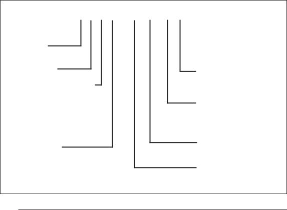
TABLE OF CONTENTS |
|
|
1. SPECIFICATIONS ................................................................................... |
|
3 |
2. OWNERS INFORMATION ....................................................................... |
|
3 |
3. MANUFACTURER WARRANTY, OWNER RESPONSIBILITY ................. |
3 |
|
4. INSTALLATION STANDARDS ................................................................. |
|
5 |
5. UNIT LOCATION ..................................................................................... |
|
6 |
6. MINIMUM CLEARANCES ........................................................................ |
|
6 |
7. RETURN AIR PROVISIONS .................................................................... |
|
6 |
8. AIR DISTRIBUTION SYSTEMS .............................................................. |
|
8 |
9. ROOF JACK SELECTION ....................................................................... |
|
8 |
10. DUCT CONNECTOR SELECTION ........................................................... |
|
9 |
11. INSTALLATION ..................................................................................... |
|
11 |
12. INSTALLATION OF TRANSIT-MODE VENTING SYSTEM ................... |
14 |
|
13. ELECTRICAL WIRING ........................................................................... |
|
15 |
14. FUEL PIPING ........................................................................................ |
|
16 |
15. FLUE GAS SAMPLING .......................................................................... |
|
19 |
16. LIGHTING AND FURNACE SHUT DOWN .............................................. |
|
20 |
17. SERVICE GUIDE ................................................................................... |
|
25 |
18. MAINTENANCE ..................................................................................... |
|
30 |
19. OPTIONAL ACCESSORIES .................................................................. |
|
31 |
20. WIRING DIAGRAMS ......................................................................... |
|
34-39 |
21. EQUIVALENT ORIFICE SIZES AT HIGH ALTITUDES .......................... |
40 |
|
M 1 M B - 056 A - B W |
|
|
Application |
|
|
M-Manufactured Home |
|
|
Furnace Series |
Door Color |
|
|
W - White |
|
Fuel, Type of Combustion |
G - Gray |
|
G-Gas, Direct Vent, Pilot Burner |
|
|
Natural or Forced Draft |
Cabinet Dimensions |
|
M-Gas, Direct Vent, HSI, |
A - 56" x 19-3/4" x 23-3/4” |
|
Forced Draft |
B - w/Coil Cavity, |
|
B-Gas, Direct Vent, Gun Burner |
76" x 19-3/4" x 23-3/4" |
|
S-Oil, Direct Vent, Gun Burner |
|
|
|
Electrical Code |
|
Comfort Model |
A - 1PH, 60 Hz, 120 VAC |
|
H - Heating |
|
|
A - Heating, A/C Ready |
Heating Capacity |
|
B - A/C Ready, 3 Ton |
Input, BTUH (000’) |
|
C - A/C Ready, 4 Ton |
|
|
D - A/C Ready, 5 Ton |
|
|
Table 1. Model Identification |
|
|
2

! WARNING:
Do not use this appliance if any part has been submerged under water. Immediately call a qualified service technician to inspect the appliance and to replace any part of the control system and any gas control that has been submerged underwater.
NOTICE TO INSTALLER
Installer is advised to follow carefully all instructions and warnings in this manual to insure maximum performance, safety, and operating efficiency of these appliances. Improper installation may create hazardous conditions, and will void the appliance warranty.
1.SPECIFICATIONS
General Description
M1 Series gas and oil furnaces are listed direct vent (sealed combustion), downflow heating appliances for manufactured (mobile) homes, recreational vehicles, and for use in residential/ modular/commercial construction. The furnace must be located so that venting can be properly achieved.
Air conditioning may be added to structures with M1 series furnaces using Platinum series air conditioning or conventional units. This Installation Instruction manual includes special requirements for incorporation of air conditioning equipment to the M1 series of furnaces.
Multi-speed blower assemblies as shown in Table 3 have been certified for field installation in M1 Series furnaces. An air conditioner can be easily field installed with M1GH Series furnaces if used in conjunction with certified 2-wire relay box, p/n 903092A or 4/5 wire relay box 902898A.
2.OWNERINFORMATION ABOUT YOUR CENTRAL FURNACE SYSTEM
NORDYNE has been involved in the design of products for the manufactured home industry since the first manufactured home or trailer was built.
NORDYNE originated the sealed combustion system, which separates the furnace combustion system from the living area of the home, now a standard for the manufactured home industry.
NORDYNE engineers developed the first central heating system and the first central air conditioner for manufactured homes.
NORDYNE is dedicated to bringing to its customers the finest heating and cooling comfort possible. NORDYNE constantly seeks to further refine its products to continuously provide exceptional comfort.
Follow the instructions in this booklet carefully and this appliance will provide many years of superior performance.
If you wish to cool your home automatically with a central air conditioning system investigate the excellent NORDYNE cooling systems available from your heating and cooling contractor. These systems are designed to work best with your NORDYNE furnace and have been carefully engineered to deliver optimum performance when mated with NORDYNE manufactured home furnaces.
NORDYNE also offers water heaters, fireplaces and ventilating systems specifically designed for manufactured housing applications. Check with your manufactured home retailer, your heating and cooling contractor or your distributor for information. Write directly to the factory (PO Box 46911, St. Louis, MO 63146) if you are not able to locate a source for NORDYNE manufactured housing products in your area.
3.MANUFACTURERWARRANTY, OWNER’S RESPONSIBILITIES
It is the sole responsibility of the homeowner to make certain the gas furnace has been correctly set up and converted to the proper fuel (L.P. gas or Natural gas) and adjusted to operate properly. All gas furnaces are manufactured for Natural gas and must be field converted when using L.P. gas.
A warranty certificate with full details is included with these instructions. However, NORDYNE will not be responsible for any costs found
3

necessary to correct problems due to improper setup, improper installation, furnace adjustments, improper operating procedure on the part of the user, etc.
Some specific examples of service calls which cannot be included in warranty payments are:
1.Converting the furnace to use another type of gas.
2.Repairing duct work in the home found to be faulty.
3.Correcting wiring problems in the electrical circuit supplying the furnace.
4.Resetting circuit breakers, blown fuses or other switches.
5.Correcting problems due to improper gas supply pressure to the furnace.
6.Providing instructional training on how to light and operate the furnace.
7.Furnace problems caused by installation of an air conditioner, heat pump or other air comfort devices.
8.Adding a Roof Jack extension because of unusual wind and/or snow conditions.
9.Revising installation of the furnace flue assembly (Roof Jack).
10.Adjusting or calibrating of thermostat.
11.Any construction debris which falls into flue system.
Furnace |
Input |
Output |
Orifice No |
E.S.P. |
Pilot |
Ignitor |
Comb. |
Motor |
A/C Ready |
|
Model No |
MBtu/h |
MBtu/h |
Nat. |
LP |
In WC |
Burner |
Direct |
Blower |
Hp |
Tons |
M1GH 056 |
56 |
45 |
29 |
45 |
0.3 |
x |
|
|
1/8 |
2* |
M1GB 056 |
56 |
45 |
29 |
45 |
0.3 |
x |
|
|
1/4 |
3 |
M1GC 056 |
56 |
45 |
29 |
45 |
0.3 |
x |
|
|
1/2 |
4 |
M1GD 056 |
56 |
45 |
29 |
45 |
0.3 |
x |
|
|
3/4 |
5 |
M1GH 070 |
70 |
57 |
24 |
42 |
0.3 |
x |
|
|
1/5 |
2½* |
M1GB 070 |
70 |
57 |
24 |
42 |
0.3 |
x |
|
|
1/4 |
3 |
M1GC 070 |
70 |
57 |
24 |
42 |
0.3 |
x |
|
|
1/2 |
4 |
M1GD 070 |
70 |
57 |
24 |
42 |
0.3 |
x |
|
|
3/4 |
5 |
M1GH 077 |
77 |
62 |
21 |
40 |
0.3 |
x |
|
x |
1/4 |
3* |
M1GB 077 |
77 |
62 |
21 |
40 |
0.3 |
x |
|
x |
1/4 |
3 |
M1GC 077 |
77 |
62 |
21 |
40 |
0.3 |
x |
|
x |
1/2 |
4 |
M1GD 077 |
77 |
62 |
21 |
40 |
0.3 |
x |
|
x |
3/4 |
5 |
M1GH 090 |
90 |
72 |
17 |
36 |
0.3 |
x |
|
x |
1/4 |
3* |
M1GB 090 |
90 |
72 |
17 |
36 |
0.3 |
x |
|
x |
1/4 |
3 |
M1GC 090 |
90 |
72 |
17 |
36 |
0.3 |
x |
|
x |
1/2 |
4 |
M1GD 090 |
90 |
72 |
17 |
36 |
0.3 |
x |
|
x |
3/4 |
5 |
M1MA 056 |
56 |
46 |
29 |
45 |
0.3 |
|
x |
x |
1/8 |
2 |
M1MB 056 |
56 |
46 |
29 |
45 |
0.3 |
|
x |
x |
1/4 |
3 |
M1MC 056 |
56 |
46 |
29 |
45 |
0.3 |
|
x |
x |
1/2 |
4 |
M1MD 056 |
56 |
46 |
29 |
45 |
0.3 |
|
x |
x |
3/4 |
5 |
M1MA 070 |
70 |
57 |
24 |
42 |
0.3 |
|
x |
x |
1/5 |
2½ |
M1MB 070 |
70 |
57 |
24 |
42 |
0.3 |
|
x |
x |
1/4 |
3 |
M1MC 070 |
70 |
57 |
24 |
42 |
0.3 |
|
x |
x |
1/2 |
4 |
M1MD 070 |
70 |
57 |
24 |
42 |
0.3 |
|
x |
x |
3/4 |
5 |
M1MB 077 |
77 |
62 |
21 |
40 |
0.3 |
|
x |
x |
1/4 |
3 |
M1MC 077 |
77 |
62 |
21 |
40 |
0.3 |
|
x |
x |
1/2 |
4 |
M1MD 077 |
77 |
62 |
21 |
40 |
0.3 |
|
x |
x |
3/4 |
5 |
M1MB 090 |
90 |
72 |
17 |
36 |
0.3 |
|
x |
x |
1/4 |
3 |
M1MC 090 |
90 |
72 |
17 |
36 |
0.3 |
|
x |
x |
1/2 |
4 |
M1MD 090 |
90 |
72 |
17 |
36 |
0.3 |
|
x |
x |
3/4 |
5 |
M1BA 066 |
66 |
53 |
26 |
43 |
0.3 |
|
x |
x |
1/5 |
2½ |
M1BB 066 |
66 |
53 |
26 |
43 |
0.3 |
|
x |
x |
1/4 |
3 |
M1BC 066 |
66 |
53 |
26 |
43 |
0.3 |
|
x |
x |
1/2 |
4 |
M1BB 086 |
86 |
68 |
18 |
37 |
0.3 |
|
x |
x |
1/4 |
3 |
M1BC 086 |
86 |
68 |
18 |
37 |
0.3 |
|
x |
x |
1/2 |
4 |
M1SA 066 |
66 |
54 |
.50 Gph |
|
0.3 |
|
x |
Burner Model |
1/5 |
2½ |
M1SB 066 |
66 |
54 |
.50 Gph |
|
0.3 |
|
x |
AF-10 Nozzle |
1/4 |
3 |
M1SC 066 |
66 |
54 |
.50 Gph |
|
0.3 |
|
x |
1/2 |
4 |
|
|
|
Spray Angle |
||||||||
M1SB 086 |
86 |
71 |
.65 Gph |
|
0.3 |
|
x |
1/4 |
3 |
|
|
|
80° A |
||||||||
M1SC 086 |
86 |
71 |
.65 Gph |
|
0.3 |
|
x |
1/2 |
4 |
|
Electrical Supply - 120 volts, 60HZ, 1 Ph. Fuse or Breaker - 15 amps
Temperature Rise - 45° to 75°F
High Altitude - See Table 11. For Canadian High Altitude (2,000’ to 4,500’), reduce the gas manifold pressure to 3.0” W.C. for natural gas and to 8” W.C. for LP gas.
Thermostat Circuit - 24 volts, 60HZ, 30 vac Normal Anticipator Setting - 0.4
Manifold Pressure - Natural Gas: 3.5” w.c. LP Gas: 10” w.c.
*Blower capacity only - needs relay box for AC
Table 2. M1 Furnace Specifications
4

Part No. |
Blower / Motor Assembly |
A/C Capacity |
||
Blower Wheel |
Motor-Hp |
Ton |
||
|
||||
903773 |
10 x 8 |
1/4 |
2, 2½ & 3 |
|
903413 |
11 x 8 |
1/2 |
2, 2½, 3 & 4 |
|
903414 |
11 x 8 |
3/4 |
2, 2½, 3, 4 & 5 |
|
Table 3. Field Installation Blower Assemblies
Carefully review these responsibilities with your manufactured housing dealer, service company or gas supplier so there will be no misunderstanding at a later time.
!CAUTION:
•Never attempt to alter or modify this furnace or any of its components.
•Never attempt to repair damaged or inoperable components. Such action could cause unsafe operation, explosion, fire and/or asphyxiation.
•If a malfunction has occurred, or if you feel that the furnace is not operating as it should, contact a qualified service agency or gas utility for assistance.
4.INSTALLATIONSTANDARDS
Installer shall be familiar with and comply with all codes and regulations applicable to the installation of these heating appliances and related equipment. In lieu of local codes, the installation shall be in accordance with the current provisions of one or more of the following standards.
“A”- 56" |
|
“A” Model- |
“B”- 76" |
w/o Coil Cabinet |
|
“B” Model- |
|
w/Coil Cabinet |
|
23 3/4"
19 3/4"
Figure 1. Overall Dimensions
6" (152 mm) Top Clearance
|
Removable access |
|
0" Side |
panel should be |
|
installed above |
||
Clearance |
||
furnace door frame |
||
to Furnace |
||
to access roof jack |
||
Cabinet |
||
|
18" |
|
|
(457 |
mm) |
Nearest |
|
Wall or |
|
|
|
|
Partition
Figure 2. Alcove Installation
6" (152 mm) Top Clearance
0" Side  Clearance to Furnace Cabinet
Provide min. 235 sq. in. (1516 cm2 ) open free area in front or side wall
or
In closet door
located at top, center
or bottom
(152 |
6" |
|
mm) |
||
|
CLOSET DOOR
Figure 3. Closet Installation
6" (152 mm) Top Clearance
0" Side  Clearance to Furnace Cabinet
Provide min. 250 sq. in. (1613 cm 2) open free area in front or side wall
or
in closet door
a fully louvered door may be used
(25 |
1" |
|
mm) |
||
|
CLOSET DOOR
Figure 4. Special 1” Clearance
5
a.Federal Manufactured Home Constructions & Safety Standard (H.U.D. Title 24, Part 3280.707[a][2])
b.American National Standard (ANSI-119.2/ NFPA-501C) for all recreational vehicle installations.
c.American National Standard (ANSI-Z223.1/ NFPA-54) and/or CAN/CGA B149 for all gasfired furnace models.
d.American National Standard (ANSI-Z95.1/ NFPA-31) and/or CSA B139 for all oil-fired furnace models.
e.American National Standard (ANSI-C1/ NFPA-70) and/or CSA 22.1 Canadian Electric Code Part 1 for all electrical field wiring.
f.Units have been investigated under standards UL 307A & B, UL727-1999, ANSI 21.47a - CAN/2.3a - 1995, and CSA B140.10.
5.UNIT LOCATION
The furnace shall be appropriately located to the supply and return air distribution system. (See “AIR DISTRIBUTION”, Page 8) Sides and back of the furnace may be enclosed by wall framing. (See “Minimum Clearances,” Table 4, and Figures 2 through 5.)
The furnace installation is only intended for free air return through the furnace door louvers. DO NOT connect a ducted return air system directly to the furnace. Improper installation may create a hazard and damage equipment, as well as void all warranties.
Furnace may be installed on combustible flooring when using NORDYNE Duct Connectors (see Section 10).
When installed in a residential garage, the furnace must be positioned so the burners and the source of the ignition are located no less than 18 inches above the floor and protected from physical damage by vehicles.
ALL MODELS |
CLOSET |
ALCOVE |
Front |
6" |
18" |
Back |
0" |
0" |
Sides |
0" |
0" |
Roof Jack |
0" |
0" |
Top |
6" |
6" |
Top and Sides of Duct |
0" |
0" |
Bottom of Duct |
|
|
B Cabinet |
0" |
0" |
A Cabinet (w/ coil box) |
0" |
0" |
A Cabinet (w/o coil box) |
1/4" |
1/4" |
Table 4. Minimum Clearances
6.MINIMUM CLEARANCES
This heating appliance must be installed with clearances not less than the minimums shown in Table 4. This heating appliance must be installed with ample clearance for easy access to the air filter, blower assembly, burner assembly, controls, and vent connections.
a.Alcove installations (see Figure 2): minimum 18" clearance at front of furnace shall be provided for future servicing. A removable access panel should be installed between top of the furnace door frame and the ceiling.
b.Closet installations must use a louvered door having a minimum free area of 235 sq. in. when located 6" from furnace (See Figure 3) or 390 sq. in. for 5 ton ready M1 furnaces. For special clearance between 1" and 6", requirements are a louvered door with a minimum of 250 sq. in. free area, with the openings in the closet door in line with the louvered openings in the furnace door . A fully louvered closet door may be used (See Figure 4 and section 7.i. to evaluate compliance with this requirement).
7.RETURN AIR PROVISIONS
U.S.A. home manufacturers shall comply with all of the following conditions to have acceptable return air systems for closet installed forced air heating appliances:
! CAUTION:
HAZARD OF ASPHYXIATION: Negative pressure inside the closet, with closet door closed and the furnace blower operating on high speed, shall be no more negative than minus 0.05 inch water column.
A Single trunk duct |
|
B |
Dual trunk duct |
w/crossover connector |
|
|
Transition duct |
C |
w/branches |
|
|
Figure 5. Non-Platinum
Supply Duct System
6
a.Regardless of the location, the return air opening into the closet shall not be less than specified in the appliance’s listing.
b.Means shall be provided to prevent inadvertent closure by a flat object placed over the return air opening when it is located in the floor of the closet (versus the vertical front or side wall).
c.The cross-sectional area of the return duct system leading into the closet, when located in the floor or ceiling shall not be less than 235 square inches (or 390 square inches for 5 ton ready M1 Furnaces).
d.The total free area of openings in the floor or ceiling registers serving the return air duct system must be at least 235 sq. in. At least one register should be located where it is not likely to be covered by carpeting, boxes and other objects.
e.Materials located in the return duct system must have a flame spread classification of 200 or less. This includes a closet door if the furnace is in a closet.
|
Approx. Length |
Model Number |
Below Flashing |
(F,S)AW(T)1523-(0,2,4)(A,S) |
15" - 23" |
(F,S)AW(T)2135-(0,2,4)(A,S) |
21" - 35" |
(F,S)AW(T)2747-(0,2,4)(A,S) |
27" - 47" |
(F,S)AW(T)3563-(0,2,4)(A,S) |
35" - 63" |
(F,S)AW(T)5195-(0,2,4)(A,S) |
51" - 95" |
|
|
S |
AW |
T |
27 47 - 2 |
|
S |
|
|
|
|||||||||||||
|
|
|
|
|
|
|
|
|
|
|
|
|
|
|
|
|
|
|
|
|
|
|
FLUE STEEL TYPE |
|
|
|
|
|
|
|
|
|
|
|
|
|
|
|
|
|
|
|
|
|
|
|
A= ALUMINIZED |
F= FLAT FLASHING |
|
|
|
|
|
|
|
|
|
|
|
|
|
|
|
|
|
|
|
|
|
|
S=STAINLESS |
|
|
|
|
|
|
|
|
|
|
MIN. ADJ. |
|
|
|
|
|
|
|
|
|||||
|
|
|
|
|
|
|
|
|
|
|
|
|
|
|
FLASHING |
||||||||
S= SLANT FLASHING |
|
TYPE: |
|
|
|
LENGTH |
|
|
|
|
|
|
|
||||||||||
|
|
|
|
|
|
|
|
|
|
|
|
|
|
|
|
|
|
|
PITCH/12" RISE |
||||
AW= ALL WEATHER |
|
BLANK=NON-TRANSIT |
|
MAX. ADJ. |
|||||||||||||||||||
|
|
0=FLAT |
|||||||||||||||||||||
|
|
|
|
|
|
T= TRANSIT MODE |
|
LENGTH |
|
|
|||||||||||||
|
|
|
|
|
|
|
|
|
2=2.5/12 |
||||||||||||||
|
|
|
|
|
|
|
|
|
|
|
|
|
|
|
|
|
|
|
|
|
|||
|
|
|
|
|
|
|
|
|
|
|
|
|
|
|
|
|
|
|
|
|
4=4/12 |
||
All Weather Roof Jack Assemblies
|
|
|
|
|
MODEL |
|
APPROX. ADJ. |
|
||||||||||
|
|
|
|
|
NUMBER |
|
LENGTHS* |
|
||||||||||
|
|
|
|
|
|
|
|
BELOW FLASHING |
|
|||||||||
|
|
|
|
|
FO1323 -5 |
|
13" - 23" |
|
|
|
|
|
||||||
|
|
|
|
|
FO2343 -5 |
|
23" - 43" |
|
|
|
|
|
||||||
|
|
|
|
|
SO1835 -5 |
|
18" - 35" |
|
|
|
|
|
||||||
|
|
|
|
|
SO2447 -5 |
|
24" - 47" |
|
|
|
|
|
||||||
|
|
|
|
|
SO3263 -5 |
|
32" -63" |
|
|
|
|
|
||||||
|
|
|
|
|
SO4895 -5 |
|
48" - 95" |
|
|
|
|
|
||||||
|
|
|
|
|
SOT2442 -5 |
|
24" - 42" |
|
|
|
|
|
||||||
|
|
|
|
|
SOT2745 -5 |
|
27" - 45" |
|
|
|
|
|
||||||
|
|
|
|
|
SOT4581 -5 |
|
45" - 81" |
|
|
|
|
|
||||||
|
|
|
|
|
FOT2846 -5 |
|
28" - 46" |
|
|
|
|
|
||||||
|
|
S O T |
27 |
45 -5 |
|
|
||||||||||||
|
|
|
|
|
|
|
|
|
|
|
|
|
|
|
|
|
|
|
S= |
|
SLAT FLASHING |
T= TRANSIT |
|
|
|
|
|
5 = 5" FLUE DIA. |
|||||||||
F= FLAT FLASHING |
MODE |
|
|
|
|
|
|
|
|
|
|
|||||||
|
|
|
|
|
|
TYPE |
|
|
|
MAX. ADJ.LENGTH |
||||||||
|
|
O= TYPE; STANDARD |
|
|
||||||||||||||
|
|
|
|
|
|
|
|
|
|
|
||||||||
|
|
H= HIGH WIND |
|
|
MIN. ADJ. |
|||||||||||||
|
|
A= ARCTIC ROOF JACK |
LENGTH |
|||||||||||||||
Table 5. Roof Jack Assemblies
f.Noncombustible pans having 1" upturned flanges are located beneath openings in a floor duct system.
g.Wiring materials located in the return duct system shall conform to Articles 300-22 of the National Electrical Code (ANSI C1/NFPA70).
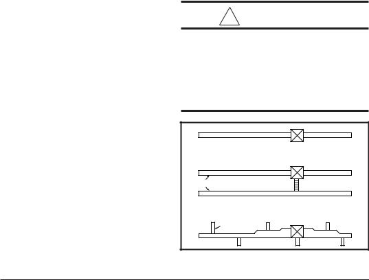
ROOF JACK
SLANT DECK
FLASHING
PITCHED
ROOF
"X" (SEE TABLE 1)
CEILING |
|
|
CAVITY |
|
|
"A" |
ROOF |
|
|
OPENING |
|
CEILING |
Flue Pipe |
|
Combustion |
||
"B" |
||
|
Air Pipe |
Furnace
56" or 76"
Figure 6. Roof Jack Assemblies
|
ROOF JACK |
|
SLANT DECK |
PITCHED |
FLASHING |
|
|
ROOF |
|
|
"X" (SEE TABLE 6) |
CEILING CAVITY |
|
CEILING |
ROOF OPENING |
|
|
|
CEILING OPENING |
Figure 7. Example of Flat Jack
with Flashing
ROOF JACK WITH 2 1 2 /12 SLANT FLASHING
2 1 2 /12 SLANT DECK
5/12 ROOF SLOPE
Figure 8. Example of 2½/12 Slant Jack
with Flashing
7

h.Gas piping is not run in or through the return duct system.
i.Test the negative pressure in the closet with the air-circulating fan operating at high speed and the closet closed. The negative pressure is to be no more negative than minus 0.05 inch water column.
j.Air conditioning systems may require more duct register and open louver area to obtain necessary airflow. Use NORDYNE’s certiduct program to determine proper duct size for A/C.
8.AIR DISTRIBUTION SYSTEMS
For proper air distribution, the supply duct system must be designed so that the static pressure measured external to the furnace does not exceed the listed static pressure rating shown on the furnace rating plate.
Location, size, and number of registers should be selected on the basis of best air distribution and floor plan of the home.
! CAUTION:
HAZARD OF ASPHYXIATION: Do not cover or restrict return air opening.
9.ROOF JACK SELECTION
Note: Install only Roof Jack Assemblies listed in Table 5 on this heating appliance.
a.Determine depth of ceiling cavity from center of roof opening to center of ceiling opening. (See Dimension “A” in Figure 6.)
b.Determine ceiling height and subtract height of furnace. (See Dimension “B” in Figure 6.)
c.Add dimensions A + B (and X from Table 6 and Figure 7 if slant deck flashing is used). The total length of (A + B + X) must be within the minimum and maximum range of one of the Roof Jacks listed in Table 5.
APPLICATION NOTES:
a.FAW, FAWT, SAW and SAWT Series Roof Jacks with a 5" diameter inner vent pipe may be used with all models of M1 Series gas and oil furnaces.
b.F=Flat Flashing; flexes from 0/12 to 1/12 roof slope.
c.S=Slant Flashing. 2.5/12 Slope flexes from 1/ 12 to 4/12 roof slope, 4/12 flexes from 3/12 to 5/12.
d.Stainless steel roof jacks are available.
e.If the roof jack crown is covered or blocked with snow, the furnace will not operate properly. If the home is located in regions where snow accumulation exceeds 7” (HUD snowload zones) use an external roof jack extension p/n 901937.
f.M1 furnaces may be used with roof jacks as tall as 170” (except M1M 056 & M1B 066 models, which are limited to 120”). An internal roof jack extension (p/n 901935 - 10”, p/n 903107 - 18”) can be used to increase roof jack height. All connections inside the home must be made below the ceiling.
These extensions are available as optional accessories and may be purchased through your NORDYNE distributor.
|
USE SLANT DECK |
|
IF ROOF PITCH IS: |
FLASHING NO. |
"X" FACTOR IS: |
|
"F Series Roof Jack |
|
|
|
|
2" in 12" |
903893 (2.5/12) |
2-1/8" |
2-1/2" in 12" |
903893 (2.5/12) |
2-1/2" |
3" in 12" |
903894 (3/12) |
2-7/8" |
3-1/2" in 12" |
903894 (3/12) |
3-1/4" |
4" in 12" |
903895 (4/12) |
3-5/8" |
"S" Series Roof Jack (2.5/12 Pitch only) |
||
|
|
|
4-1/2" in 12" |
903895 (2.5/12) |
2-1/8" |
5" in 12" |
903895 (2.5/12) |
2-1/2" |
5-1/2" in 12" |
903894 (3/12) |
2-7/8" |
6" in 12" |
903894 (3/12) |
3-1/4" |
6-1/2" in 12" |
903895 (4/12) |
3-5/8" |
Optional Deck Flashings for Flat and 2.5/12 Pitch Roof Jacks.
(4/12 Pitch Roof Jacks not applicable.)
Table 6. Slant Deck Flashings
|
|
Use Duct Connector |
|
If "X" (Floor Cavity) is: |
Model Part Number: |
||
English |
Metric (mm) |
Finger Tab |
Screw Down |
7/8" |
22 |
901987 |
904008 |
2" |
51 |
901988 |
904009 |
4-1/4" |
108 |
901989 |
904010 |
6-1/4" |
159 |
901990 |
904011 |
8-1/4" |
210 |
901991 |
904012 |
10-1/4" |
260 |
901992 |
904013 |
12-1/4" |
311 |
901993 |
904014 |
Table 7. Floor Cavity Sizes
8
10. DUCT CONNECTOR SELECTION
PLATINUM SERIES
a.For Platinum ready construction use the 14” round duct connector, p/n: 903896.
NON-PLATINUM SERIES
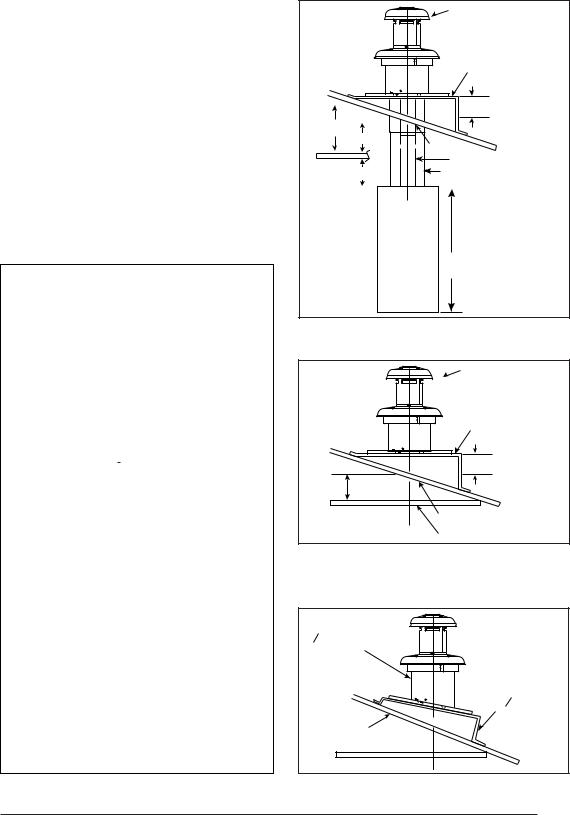
a.Determine depth of floor cavity from surface of floor to top of supply air duct (See Figure 9).
b.Select appropriate model from Table 7 which matches X-dimension of the floor cavity. To maximize air delivery, remove reducer “C” (see Figure 11) to obtain the largest open area that will fit the duct/floor construction. Screw down duct connector opening to duct without reducer is 13” x 13”. With reducer it is 13” x 10-1/8”.
FLOOR CAVITY
(depth equal to "X" in Figure 11 and Table 7)
x
SUPPLY AIR DUCT
Figure 9.
19” |
|
|
13 1/4" |
19" |
|
10 1/4" |
||
|
||
Figure 10. |
|
Top View
of
Finger Tab
Duct
Connector
|
REDUCER |
*FELT-SEAL |
C |
|
*OPENING TO DUCT
WITH PLATE (C) REMOVED OPENING BECOMES 13-1/4” x 13-1/4”
|
X |
SEE |
|
SPACERS |
TABLE 7 |
||
|
|||
|
*INDICATES FINGER TAB DUCT CONNECTOR ONLY |
|
Figure 11.
9
C
CEILING AND ROOF
OPENINGS
L
13-1/2"
C
L
WALL
SIDE
ALT. FUEL
LINE HOLES
C
L
FUEL LINE
HOLE
REAR W
ALL
10"
C
FLOOR
OPENING
L
23 -1/4"
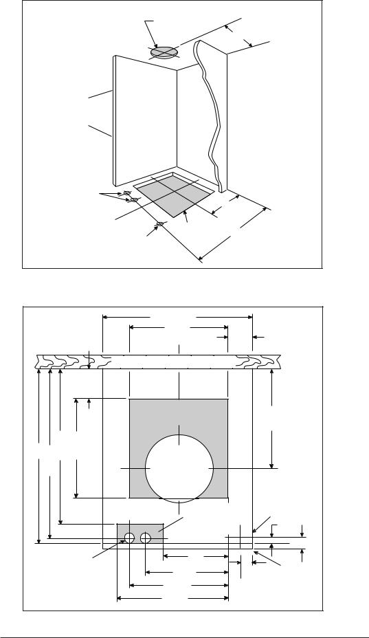
Figure 12. Closet or Alcove
|
|
|
|
|
20" |
|
|
|
|
|
|
|
|
|
|
|
|
14-1/2" |
|
|
|
|
|||
|
|
|
|
|
C |
|
|
|
|
|
2-3/4" |
|
|
|
|
|
|
L |
|
|
|
|
|
||
|
|
|
|
REAR WALL OF CLOSET OR ALCOVE |
|
|
||||||
|
|
|
|
2-1/4" |
FLOOR CUT-OUT |
FURNACE OUTLINE |
13-1/2" |
|||||
|
|
|
|
FOR DUCT CONN. |
||||||||
24" |
1/4" |
21-3/4" |
14-1/2" |
CEILING |
FOR |
|
|
|||||
AND |
|
|||||||||||
|
- |
|
|
C |
|
|
|
|||||
|
|
|
|
|
|
|
||||||
|
23 |
|
|
OUT |
|
|
|
|||||
|
|
|
L |
- |
|
|
JACK |
|
|
|||
|
|
|
|
|
CUTFLUE |
|
|
Fig |
12) |
|
|
|
|
|
|
|
|
ROOF |
|
|
|
|
|||
|
|
|
|
|
|
(See |
|
|
|
|
||
|
|
|
|
C |
|
|
FLOOR CUT-OUT |
|
FUEL-LINE |
|||
|
|
|
|
|
|
FOR OPTIONAL |
|
|||||
|
|
|
|
L |
|
|
|
COOLING COIL |
|
|
||
|
|
|
|
|
|
|
|
|
3/4" |
|||
|
|
|
|
|
FOR NON-PLATINUM |
|
||||||
|
|
|
|
|
|
|
||||||
|
|
|
|
|
C SERIES UNITS |
|
|
|||||
|
|
|
|
|
L |
|
|
|
|
|
|
2" |
|
|
|
|
|
|
|
|
|
|
|
|
|
|
|
|
1-1/4" D. |
|
|
|
|
10" |
|
|
||
|
|
ALT FUEL-LINE |
|
|
|
|
|
|
|
|
||
|
|
|
ENTRY |
12-7/8" |
|
1-3/4" |
FURNACE |
|||||
|
|
|
|
|
|
|
|
|
|
|
|
OUTER DOOR |
|
|
|
|
|
14-3/4" |
|
|
|
|
|||
|
|
|
|
|
15-1/2" |
|
|
|
|
|
||
Figure 13. Cut-Out Locations
10
11. INSTALLATION
Required floor, ceiling, and roof cut-out openings must be carefully located to avoid misalignment of the furnace and Roof Jack (see Figures 12 & 13). Installation procedures are suggested for typical furnace installations and need not be followed in the exact listed sequence.
CUT OUT FLOOR OPENING & FUEL LINE HOLE
a.Determine center of closet or alcove (Figure 13).
b.Locate center of the floor opening, measured 10" from the rear wall, and mark cut-out measuring approximately 14-1/2" by 14-1/2" (± 1”) for model duct connector used (refer to Figures 10 & 11).
c.Locate center of fuel line hole, measured 23- 1/4" from the rear wall and 6-5/8" to the left of center of the floor cut-out (See Figure 12) or
5-1/4" to the left of center of the floor cut-out, or for entry through right-side of furnace measured 9" to the right of center of the floor cut-out.
d. Cut out floor opening and one fuel line hole.
! IMPORTANT:
Refer to the installation instructions provided with optional air conditioning packageswheninstallingfurnaceswith optional cooling coil cabinet or with optional C***-series indoor coils.
CUT OUT CEILING AND ROOF OPENINGS
a.Locate center of Roof Jack opening, measured 13 1/2" from the rear wall of closet or alcove along the center line of furnace and floor opening. (See Figure 13)
MOUNTING |
REAR WALL |
|
PLATE |
||
|
FLOOR
OPENING
FUEL
LINE
HOLES
SUPPLY AIR DUCT
CUT DUCT OPENING 1/16TH. LARGER THAN DUCT CONNECTOR
Figure 14. Mounting Plate
|
|
MOUNTING |
SCREWS |
|
|
|
|
|
UNDER DUCT OPENING |
PLATE |
|
|
|
|
|
MOUNTING |
REAR WALL |
DUCT |
|
CONNECTOR |
|
||
PLATE |
|
||
|
|
||
|
|
|
|
FLOOR |
|
|
|
OPENING |
|
|
|
FUEL |
|
|
FUEL |
LINE |
|
|
|
|
|
LINE |
|
HOLES |
|
|
|
|
|
HOLES |
|
|
|
|
|
SUPPLY AIR DUCT |
|
|
|
Non-Platinum Series |
Platinum Series |
14” SUPPLY |
|
CONNECTION |
|||
Figure 15. Duct Connector
11
b.Cut ceiling and roof holes as follows: Ceiling Hole = 8-3/4" (222 mm) diameter Roof Hole = 9-3/8" (238 mm) diameter
c.DO NOT ALLOW DEBRIS TO FALL INTO THE FURNACE. THIS COULD CAUSE UNSAFE OPERATION AND VOIDS THE FURNACE WARRANTY. Use the top cap that comes with the furnace packaging (or alternate protector) to prevent debris from falling into the furnace before the final roof jack connection is made.
CUT DUCT OPENING (FINGER TABBED ONLY)
a.Place duct connector through the floor opening with bottom tabs resting on top of the supply air duct.
b.Center duct connector and push back against rear edge of floor opening.
c.Mark cut-out location (tab area) and remove duct connector.
d.Cut out duct opening 1/4" larger than area marked.
INSTALL FURNACE MOUNTING PLATE
a.Place mounting plate (supplied within duct connector) at rear of the floor opening (See Figure 15).
INSTALLING PLATINUM SERIES 14” ROUND DUCT CONNECTOR
a.Place duct connector through the floor opening. (See Figure 15).
b.Secure duct connector to floor.
INSTALLING SCREW DOWN DUCT CONNECTOR
a.Apply a bead of caulking, mastic, or other approved sealant around bottom side of 1/2” flange and restrictor plate, when applicable.
b.Locate the duct connector over duct and carefully lower screw down duct connector into place.
c.Once duct connector is located on duct, temporarily hold in place while fastening duct connector to the floor using flat head screws or nails. Be sure flanges of duct connector stay in contact with the duct.
d.Screw plenum to duct making sure a seal is made between the duct and the duct connector. Additional screws may be added if required.
e.Cut away duct along edge of flange allowing the center to drop into the duct. Remove section of duct with caution, as edges will be sharp.
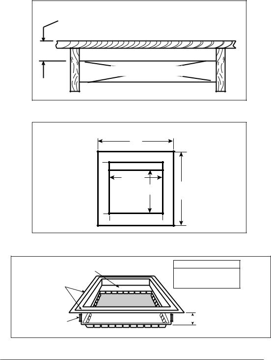
INSTALLING FINGER TABBED DUCT CONNECTORS
a.Place duct connector through the floor opening with bottom tabs extending through the duct opening. (See Figure 15)
b.Secure duct connector to floor.
c.Bend bottom tabs under and up tightly against the supply air duct (See Figure 16).
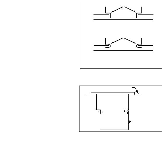
NOTE: The duct connector is designed for use on ducts 12" in width. When using the connector on 12" wide ducts, there may be insufficient clearance to bend the tabs on two sides of the duct connector. In such cases the tabs may be attached to the sides of the duct by using sheet metal screws or other suitable fasteners. (See Figure 17).
If sealant, mastic, or tape is used to provide a better seal, it should be approved by applicable national or local codes.
ALTERNATE ATTACHMENT METHODS
This procedure may also be used to install a furnace duct connector to narrow metal ductwork where insufficient clearance prevents
TABS
DUCT
1.INSERT DUCT CONNECTOR INTO DUCT CUT-OUT.
TABS
DUCT
2.BEND BOTTOM TABS OVER AND ONTO THE UNDERNEATH DUCT SERVICE.
Figure 16. Installation of Duct Connector
Duct Connector
 Narrow Duct
Duct
Figure 17.
12
 Loading...