


Direct Vent (Sealed Combustion) Forced Air Gas Furnaces
Installation Instructions
M3RL Series 90+ Downflow Condensing Furnace
For installation in:
1.Manufactured Homes
2.Park Models and Manufactured Buildings
3.Modular Homes/Buildings
! WARNING:
FIRE OR EXPLOSION HAZARD
Failure to follow safety warnings exactly could result in serious injury, death or property damage.
–Do not store or use gasoline or other flammable vapors and liquids in the vicinity of this or any other appliance.
–WHAT TO DO IF YOU SMELL GAS
•Do not try to light any appliance.
•Do not touch any electrical switch; do not use any phone in your building.
•Leave the building immediately.
•Immediately call your gas supplier from a neighbor's phone. Follow the gas supplier's instructions.
•If you cannot reach your gas supplier, call the fire department.
–Installation and service must be performed by a qualified installer, service agency, or the gas supplier.
! ADVERTISSEMENT:
RISQUE D’INCENDIE OU D’EXPLOSION
Le non-respect des avertissements de sécurité pourrait entraîner des blessures graves, la mort ou des dommages matériels.
–Ne pas entreposer ni utiliser de l’essence ni d’autres vapeurs ou liquides inflammables dans le voisinage de cet appareil, ni de tout autre appareil.
–QUE FAIRE S’IL Y A UNE ODEUR DE GAZ
•Ne pas tenter d’allumer aucun appareil.
•Ne toucher à aucun interrupteur électrique; n’utiliser aucun téléphone dans le bâtiment.
•Évacuer l’immeuble immédiatement.
•Appeler immédiatement le fournisseur de gaz en employant le téléphone d’un voisin. Respecter à la lettre les instructions du fournisseur de gaz.
•Si personne ne répond, appeler le service des incendies.
–L’installation et l’entretien doivent être effectués par un installateur qualifié, un organisme de service ou le fournisseur de gaz.
BW Models
BWT Models
! WARNING:
Should overheating occur, or the gas supply fail to shut off, shut off the manual gas valve to the appliance before shutting off the electrical supply.
Improper installation, adjustment, alteration, service or maintenance can cause injury or property damage. Refer to this manual. For assistance or additional information consult a qualified installer, service agency or the gas supplier.
LEAVE THESE INSTRUCTIONS WITH THE HOMEOWNER.

2

TABLE OF CONTENTS
General ...................................................... |
4 |
Unit Dimensions .................................. |
4 |
Shipping Weights ................................ |
4 |
Furnace Specification ........................ |
4 |
Air Flow Data ..................................... |
4 |
Owner's Information ................................ |
5 |
Installation Requirements ...................... |
6 |
Location .............................................. |
7 |
Clearance ........................................... |
7 |
Circulating Air Supply ............................ |
7 |
Return Air Provisions .............................. |
8 |
Air Distribution Systems ........................ |
9 |
Duct Connector Selection .................... |
10 |
Duct Installation .................................... |
10 |
Venting and Combustion |
|
Air Requirements ........................... |
13 |
Venting Requirements .......................... |
14 |
Vent Table ........................................ |
15 |
Vent Pipe Material ............................ |
16 |
Vent Pipe Length and Diameter ....... |
16 |
Vent Pipe Installation ........................ |
16 |
Pipe Routing & Support .................... |
16 |
Location of Outdoor Termination ..... |
16 |
Horizontal Venting ............................ |
18 |
Vertical Venting ................................ |
18 |
Vent Freezing Protection ................. |
19 |
Concentric Vent Termination ........... |
19 |
Drainage of Condensate |
|
From Furnace ................................ |
19 |
Gas Supply and Piping ......................... |
20 |
Leak Check ....................................... |
21 |
High Altitude Derate ......................... |
21 |
Pressure Switch .............................. |
21 |
Conversion .............................................. |
21 |
Lighting and Adjustment |
|
of the Appliance .............................. |
23 |
Electrical Wiring ...................................... |
24 |
Line Voltage Wiring ........................... |
24 |
Low Voltage Wiring ........................... |
26 |
Ventilation ................................................ |
26 |
Start-up and Adjustment ........................ |
26 |
Start-Up Procedure ........................... |
26 |
Shut Down Procedure ....................... |
27 |
Verifying and Adjusting Firing Rate ... |
27 |
Temperature Rise ............................. |
27 |
Verifying and Adjusting |
|
Verifying Burner Operation .............. |
28 |
Verifying Operation of the |
|
Supply Air Limit Switch ................. |
28 |
Description of Components ................ |
29 |
Furnace Accessories ............................. |
29 |
Maintenance ........................................... |
29 |
Combustion Air and Vent System .... |
29 |
Air Filter(s) ....................................... |
29 |
Lubrication ........................................ |
30 |
Condensate Drain Assembly ........... |
30 |
Blower Compartment ....................... |
30 |
Heat Exchanger and Burner |
|
Maintenance .................................. |
30 |
System Operation Information ............. |
30 |
Sequence of Operation .................... |
30 |
Furnace Fails to Operate ................. |
31 |
Location of Major Components .......... |
32 |
Wiring Diagram ....................................... |
33 |
Installation/Performance |
|
Checklist ......................................... |
35 |
M 3 R L - 060 A - A W
|
|
|
|
|
|
|
|
|
|
|
|
|
|
Return Air Configuration |
|
|
|
|
|
|
|
|
|
|
|
|
|
|
|
|
|
|
|
|
|
|
|
|
|
|
|
|
|
|
|
|
|
|
|
|
|
|
|
|
|
|
|
|
Blank - Front |
Application |
|
|
|
|
|
|
|
|
|
|
|
|
|
T - Top |
|
|
|
|
|
|
|
|
|
|
|
Door Color |
|||
M-Manufactured Home |
|
|
|
|
|
|
|
|
|
|||||
|
|
|
|
|
|
|
|
W - White |
||||||
|
|
|
|
|
|
|
|
|
|
|
|
|
||
Furnace Series |
|
|
|
|
|
|
|
|
|
|
|
G - Gray |
||
|
|
|
|
|
|
|
|
|
|
Cabinet Dimensions |
||||
Comfort Model |
|
|
|
|
|
|
|
|
||||||
|
|
|
|
|
|
|
||||||||
|
|
|
|
|
|
|
|
A - 56" x 19-3/4" x 23-3/4” |
||||||
|
|
|
|
|
|
|
||||||||
RL - Condensing Downflow |
|
|
|
|
|
|
B - w/Coil Cavity, |
|||||||
|
|
|
|
|
|
|
|
|
|
|
|
|
|
76" x 19-3/4" x 23-3/4" |
|
|
|
|
|
|
|
|
|
|
|
|
|
Electrical Code |
|
|
|
|
|
|
|
|
|
|
|
|
|
|
||
|
|
|
|
|
Heating Capacity |
|
A - 1PH, 60 Hz, 120 VAC |
|||||||
|
|
|
|
|
Input, BTUH (000’) |
|
|
|
||||||
|
|
|
|
|
|
|
|
|
|
|
|
|
|
|
|
|
|
|
|
Table 1. Model Identification |
|
|
|
||||||
3

GENERAL
21-11/32 COMBUSTION AIR INTAKE
 17-13/16
  EXHAUST VENT
SIDE RETURN
KNOCKOUTS
21-17/32
21-29/32
20-9/32
1-19/32
7/8 Diameter |
28-15/32 |
23-7/16 |
3-17/32 |
4-11/16 |
19-7/8 |
1-1/2 |
|
|
3-17/32 |
|
24-5/8 |
|
|
|
||
|
COMBUSTION AIR INTAKE |
|
|
|
1-11/16 |
|
|
|
EXHAUST |
|
|
|
VENT |
|
|
|
|
18-1/2 |
SIDE RETURN |
|
|
KNOCKOUTS |
|
|
|
|
|
|
|
|
18-1/2 |
|
56-1/16 |
|
|
|
|
|
(W/ Coil Box) |
|
|
|
75-1/4 |
|
(W/O Coil Box) |
|
|
|
3-17/32 |
|
2121-15/16-15/16 |
|
|
11-19-19/32/32 |
|
|
|
|
|
|
4-11/16 |
|
|
Cooling |
19-3/16 |
|
|
Coil |
|
|
|
|
|
|
|
Box |
|
|
|
20-1/16 |
|
|
24-3/4 |
|
|
|
Figure 1. Furnace Dimensions
TopReturn Knockouts

 1.000
1.000
1.000
 12.000
|
|
|
Shipping |
|
|
|
|
Weight |
|
|
21.000 |
Furnace Model |
(lbs) |
|
|
|
M3RL 060A AW |
150 |
|
|
|
M3RL 060A BW* |
170 |
|
|
|
M3RL 080A AW |
155 |
|
|
|
M3RL 080A BW* |
175 |
|
|
|
* May include suffix - T |
|
|
Top View |
Top Return Opening |
Table 2. Shipping Weight |
||
(AW and BW Models) |
(BWT Models) |
|||
|
|
|||
Furnace Specifications / Airflow Data
|
Furnace |
Furnace |
Temp. |
|
|
External Static Pressure ( Inches Water Column) |
Recommended |
||||
Furnace |
Input |
Output |
Rise @ |
Motor |
Motor |
0.1 |
0.2 |
0.3 |
0.4 |
0.5 |
A/C |
Model No. |
Btuh |
Btuh |
.3"WC °F |
HP |
Speed |
CFM |
CFM |
CFM |
CFM |
CFM |
Ton |
|
|
|
|
|
High* |
1660 |
1599 |
1544 |
1474 |
1410 |
4 |
|
|
|
|
|
Med-High |
1512 |
1467 |
1416 |
1363 |
1304 |
3 |
|
|
|
|
|
Med-Low |
1340 |
1304 |
1261 |
1217 |
1158 |
2.-1/2 |
M3 RL-060 |
60,000 |
54,000 |
35 - 65 |
1/2 |
Low** |
1176 |
1142 |
1108 |
1025 |
966 |
2 |
|
|
|
|
|
High* |
1660 |
1599 |
1544 |
1474 |
1410 |
4 |
|
|
|
|
|
Med-High |
1512 |
1467 |
1416 |
1363 |
1304 |
3 |
|
|
|
|
|
Med-Low** |
1340 |
1304 |
1261 |
1217 |
1158 |
2.-1/2 |
M3 RL-080 |
80,000 |
72,000 |
35 - 65 |
1/2 |
Low |
1176 |
1142 |
1108 |
1025 |
966 |
2 |
Note: Data is for Operation with Filter.
*Factory Wired Cooling Tap
**Factory Wired Heating Tap
Table 3. Furnace Specifications/Airflow Data
4

! WARNING:
Do not use this appliance if any part has been submerged under water. Immediately call a qualified service technician to inspect the appliance and to replace any part of the control system and any gas control that has been submerged underwater.
NOTICE TO INSTALLER
Installer is advised to follow carefully all instructions and warnings in this manual to insure maximum performance, safety, and operating efficiency of these appliances. Improper installation may create hazardous conditions, and will void the appliance warranty.
GENERAL
General Description
The M3 series gas furnaces are listed direct vent (sealed combustion) forced air furnaces for use with both natural and propane gases. The M3 series is a Category IV and type FSP furnace. The M3 furnace series has been certified to the ANSI Z21.47/CSA2.3-2001 for use in the United States and Canada and to the UL307B —1995 for use in the United States.
These furnaces may be installed in:
1.Manufactured Homes.
2.Park Models and Manufactured buildings
3.Modular Homes/Buildings
The following are safety guidelines with references to their specific sections or pages in the manual.
1.Use only type of gas approved for this furnace. Refer to the furnace rating plate.
2.Install this furnace only in location and position as specified in pages 7 - 13 of these instructions.
3.Provide adequate combustion and ventilation air to the furnace space as specified in pages 13 - 20 of these instructions.
4.Combustion products must be discharged outdoors, connect this furnace to an approved vent system only, as specified in pages 14-19 of these instructions.
5.Never test for gas leaks with an open flame. Use a commercially available soap solution made specifically for the detection of leak to check all connections.
6.Always install furnace to operate within the furnace’s intended temperature rise range with a duct system that has an external static pressure within the allowable range, as specified in page 4 of these instructions. See furnace rating plate.
7.When a furnace is installed so that supply ducts carry air circulated by the furnace to areas outside the space containing the furnace, the return air shall also be handled by duct(s) sealed to the furnace casing and terminating outside the space containing the furnace. Note: This section only applies to furnaces installed with side or top return air.
8.A gas-fired furnace for installation in a residential garage must be installed as specified in page 7 of these instructions.
9.The furnace is not to be used for temporary heat of buildings or structures under construction.
M3 series furnaces are air conditioning ready as shipped. The furnace cooling capacities of the blower motor speed taps are shown in Table 3. Table 2 lists the shipping weights for the M3 series furnaces.
OWNER INFORMATION
NORDYNE has been involved in the design of products for the manufactured home industry since the first manufactured home or trailer was built.
NORDYNE originated the sealed combustion system, which separates the furnace combustion system from the living area of the home, now a standard for the manufactured home industry.
NORDYNE engineers developed the first central heating system and the first central air conditioner for manufactured homes.
NORDYNE is dedicated to bringing to its customers the finest heating and cooling comfort possible. NORDYNE constantly seeks to further refine its products to continuously provide exceptional comfort.
5

Follow the instructions in this booklet carefully and this appliance will provide many years of superior performance.
If you wish to cool your home automatically with a central air conditioning system investigate the excellent NORDYNE cooling systems available from your heating and cooling contractor. These systems are designed to work best with your NORDYNE furnace and have been carefully engineered to deliver optimum performance when mated with NORDYNE manufactured home furnaces.
NORDYNE also offers water heaters, fireplaces and ventilating systems specifically designed for manufactured housing applications. Check with your manufactured home retailer, your heating and cooling contractor or your distributor for information. Write directly to the factory (PO Box 8809, O’Fallon, MO 63366) if you are not able to locate a source for NORDYNE manufactured housing products in your area.
MANUFACTURER WARRANTY, OWNER’S RESPONSIBILITIES
It is the sole responsibility of the homeowner to make certain the gas furnace has been correctly set up and converted to the proper fuel (L.P. gas or Natural gas) and adjusted to operate properly. All gas furnaces are manufactured for Natural gas and must be field converted when using L.P. gas.
A warranty certificate with full details is included with these instructions. However, NORDYNE will not be responsible for any costs found necessary to correct problems due to improper setup, improper installation, furnace adjustments, improper operating procedure on the part of the user, etc.
Some specific examples of service calls which cannot be included in warranty payments are:
1.Converting the furnace to use another type of gas.
2.Repairing duct work in the home found to be faulty.
3.Correcting wiring problems in the electrical circuit supplying the furnace.
4.Resetting circuit breakers, blown fuses or other switches.
5.Correcting problems due to improper gas supply pressure to the furnace.
6.Providing instructional training on how to light and operate the furnace.
7.Furnace problems caused by installation of an air conditioner, heat pump or other air comfort devices.
8.Revising installation of the furnace flue assembly.
9.Adjusting or calibrating of thermostat.
10.Any construction debris which falls into the flue system.
Carefully review these responsibilities with your manufactured housing dealer, service company or gas supplier so there will be no misunderstanding at a later time.
!CAUTION:
•Never attempt to alter or modify this furnace or any of its components.
•Never attempt to repair damaged or inoperable components. Such action could cause unsafe operation, explosion, fire and/or asphyxiation.
•If a malfunction has occurred, or if you feel that the furnace is not operating as it should, contact a qualified service agency or gas utility for assistance.
INSTALLATION STANDARDS
Installer shall be familiar with and comply with all codes and regulations applicable to the installation of these heating appliances and related equipment. In lieu of local codes, the installation shall be in accordance with the current provisions of one or more of the following standards.
a.Federal Manufactured Home Constructions & Safety Standard (H.U.D. Title 24, Part 3280.707[a][2])
b.The Standard for Manufactured Home Installations (Manufactured Home Sites, Communities, and Set-Ups) ANSI A225.1 and/or CAN/CSA-2240 MH Series).
c.American National Standard (ANSI-119.2/ NFPA-501C) for all recreational vehicle installations.
d.American National Standard (ANSI-Z223.1/ NFPA-54) and/or CAN/CGA B149 for all gasfired furnace models.
e.American National Standard (ANSI-C1/NFPA- 70) and/or CSA 22.1 Canadian Electric Code Part 1 for all electrical field wiring.
6
CE générateur d'air chaud doit être installé conformément aux instructions du fabricant et aux codes locaux. En l'absence de code local, respecter la norme ANSI Z223.,1, institulé National Fuel Gas Code ou les codes d'installation CAN/GCA-B149.
The National Fuel Gas Code is available by writing:
American National Standards Institute, Inc.
1430 Broadway
New York, NY 10018
NFPA publications are available by writing:
National Fire Protection Association
Batterymarch Park
Quincy, ME 02269
LOCATION
The furnace must be installed on a level surface, and as close to the center of the air distribution system as possible. See Figure 1 for overall dimensions to determine the required clearances in hallways, doorways, stairs, etc. to allow the furnace to be moved to the installation point. The furnace must be installed so that all electrical components are protected from water.
Minimum clearances to combustible materials are listed in Table 4. Access for positioning and servicing must be considered when locating the unit.
This furnace is certified for use on wood flooring. The furnace must be installed on a solid surface and must be level front-to-back and side-to-side. This furnace must not be installed directly on carpeting, tile, or any com-
|
CLOSET |
ALCOVE |
ALL MODELS |
Inches |
Inches |
Front |
1* |
1* |
Back |
0 |
0 |
Sides |
0 |
0 |
Vent |
0 |
0 |
Top |
6 |
6 |
Duct (Plenum) |
|
|
w/ Coil Box |
0 |
0 |
w/o Coil Box |
1/4 |
1/4 |
(within 3 feet) |
|
|
*Note: For 1” clearance, use a fully louvered door with at least 400 square inches of free airflow area.
Table 4. Minimum Clearances
bustible material other than wood flooring. The furnace may be installed on combustible flooring when installed on a Nordyne duct connector (see Table 5).
The ductwork within 3 feet of the furnaces without the A/C coil box must be installed such that surfaces are at least 1/4" from combustible materials.
When installed in a residential garage, the furnace must be positioned so the burners and the source of the ignition are located no less than 18 inches above the floor and protected from physical damage by vehicles.
CIRCULATING AIR SUPPLY
! WARNING:
Products of combustion must not be allowed to enter the return air openings of the furnace or the circulating air supply. Failure to prevent products of combustion from being circulated into the living space can create potentially hazardous conditions including carbon monoxide poisoning that could result in personal injury or death.
The floor or platform on which the furnace is mounted must provide sound physical support of the furnace with no gaps, cracks, or sagging between the furnace and the floor or platform.
The circulating air ductwork must not be connected to any other heat producing device such as a fireplace insert, stove, etc.
GENERAL
Plenums and air ducts must be installed in accordance with the Standard for the Installation of Air Conditioning and Ventilating Systems (NFPA No. 90A) or the Standard for the Installation of Warm Air Heating and Air Conditioning Systems (NFPA No. 90B).
7
RETURN AIR PROVISIONS
U.S.A. home manufacturers shall comply with all of the following conditions to have acceptable return air systems for closet installed forced air heating appliances:
a.Regardless of the location, the return air opening into the closet shall not be less than specified in the appliance’s listing.
b.Means shall be provided to prevent inadvertent closure by a flat object placed over the return air opening when it is located in the floor of the closet (versus the vertical front or side wall).
c.Closet installations must use a louvered door having a minimum free area of 235 sq. in. when located 6” from furnace. For clearance between 1” and 6” from furnace, requirements are a louvered door with minimum of 235 sq. in. free area, with the openings in closet door directly inline with the louvered openings in the furnace door. For 1” clearance from furnace, use a fully louvered door with at least 400 sq. in. of free airflow area.
d.The cross-sectional area of the return duct system leading into the closet, when located
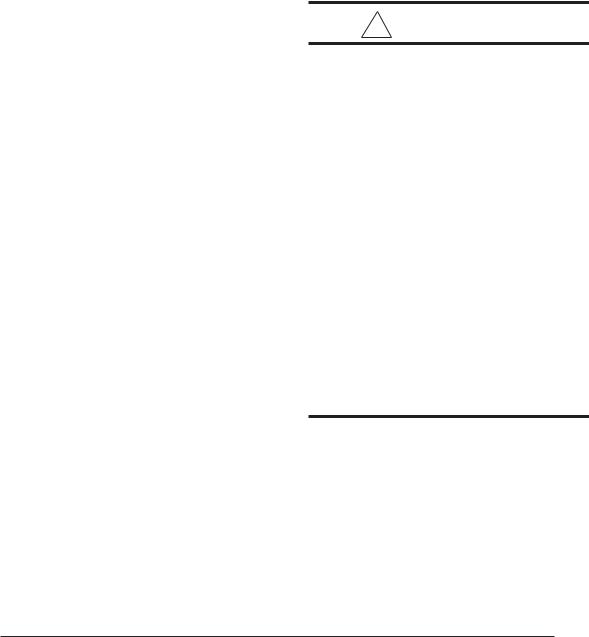
A Single trunk duct |
||
B |
Dual trunk duct |
|
w/crossover connector |
||
|
||
|
Transition duct |
|
C |
w/branches |
|
|
||
Figure 2. Non-Platinum
Supply Duct System
in the floor or ceiling shall not be less than 235 square inches.
e.The total free area of openings in the floor or ceiling registers serving the return air duct system must be at least 352 sq. in. At least one register should be located where it is not likely to be covered by carpeting, boxes and other objects.
f.Materials located in the return duct system must have a flame spread classification of 200 or less. This includes a closet door if the furnace is in a closet.
g.Noncombustible pans having 1" upturned flanges are located beneath openings in a floor duct system.
h.Wiring materials located in the return duct system shall conform to Articles 300-22 of the National Electrical Code (ANSI C1/ NFPA-70).
19” |
|
|
|
|
13 1/4" |
|
Top View |
||
|
of Duct |
|||
10 |
1/4" |
19" |
||
Connector |
||||
|
||||
|
|
|
||
|
Figure 4. |
|
||
|
|
|
Use Duct Connector |
|
If "X" (Floor Cavity) is: |
Model Part Number: |
|||
English |
Metric (mm) |
Finger Tab |
Screw Down |
|
7/8" |
22 |
901987 |
904008 |
|
|
2" |
51 |
901988 |
904009 |
4 |
1/4" |
108 |
901989 |
904010 |
6 |
1/4" |
150 |
901990 |
904011 |
8 |
1/4" |
210 |
901991 |
904012 |
10 1/4" |
260 |
901992 |
904013 |
|
12 1/4" |
311 |
901993 |
904014 |
|
Table 5. Duct Connectors
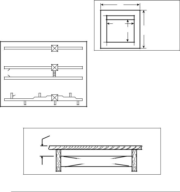
FLOOR CAVITY
(depth equal to "X" in Figure 5 and Table 5)
x
SUPPLY AIR DUCT
Figure 3.
8
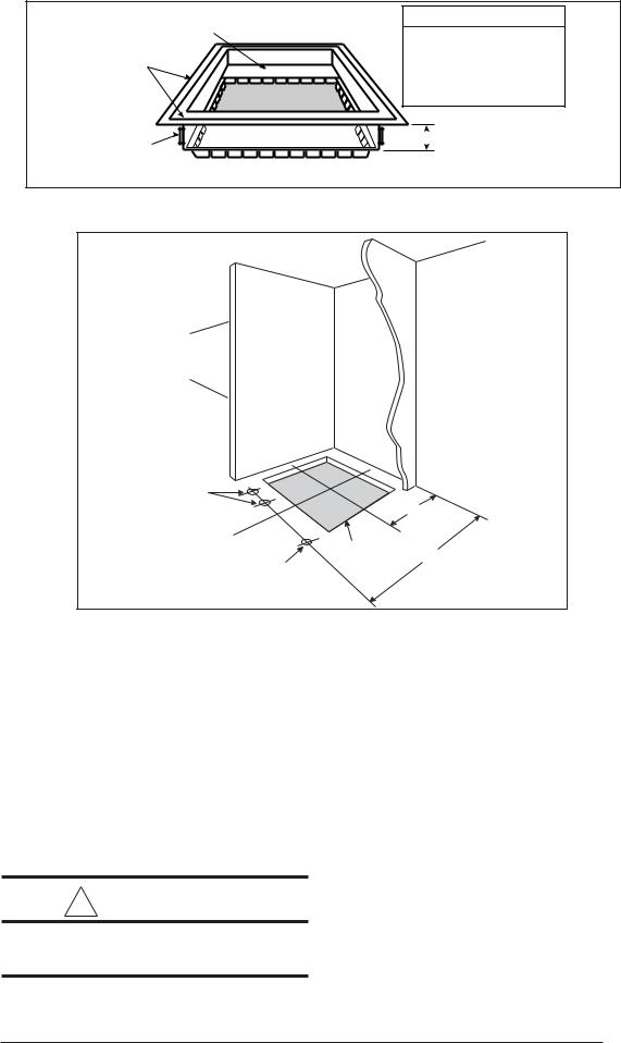
|
REDUCER |
FELT-SEAL(1) |
C |
|
SPACERS
(1)FINGER TAB DUCT CONNECTOR ONLY
(2)SCREW DOWN DUCT CONNECTOR ONLY
( )OPENING TO DUCT
(1)WITH PLATE (C) REMOVED OPENING BECOMES 13-1/4” x 13-1/4”
(2)WITH PLATE (C) REMOVED OPENING BECOMES
13" X 13". WITH REDUCER IT IS 13" X 10-1/8".
X SEE
TABLE 5
Figure 5.
WALL
SIDE
ALT. FUEL
LINE HOLES
C
L
FUEL LINE
HOLE
REAR |
WALL |
|
10"
C
FLOOR
OPENING
L
23 -1/4"
Figure 6. Closet or Alcove
i.Gas piping is not run in or through the return duct system.
j.Test the negative pressure in the closet with the air-circulating fan operating at high speed and the closet closed. The negative pressure is to be no more negative than minus 0.05 inch water column.
k.For floor return systems, the manufactured home manufacturer shall affix a prominent marking on or near the appliance where it can be easily read when the closet door is open. The marking shall read:
! CAUTION:
HAZARD OF ASPHYXIATION: Do not cover or restrict return air opening.
l.Air conditioning systems may require more duct register and open louver area to ob-
tain necessary airflow. Use NORDYNE’s certiduct program to determine proper duct size for A/C.
DUCTED RETURN AIR
M3 furnaces with model numbers ending in AW or BW are factory configured for the return air to flow through the front louvered door. The return air may also be attached to either side or the top of the furnace cabinet using a field installed kit. Refer to Table 12 for the NORDYNE ducted return kit P/N number. The location and size of the side and top return air connections are shown in Figure 1. The filter size for the side return air is 20” x 20” x 1”. For top return the filter size is 24” x 16” x 1”.
M3 furnaces with model numbers ending in BWT are factory configured for the return air to enter the top of the furnace.
9
|
|
|
20 |
|
|
|
|
|
|
14-1/2 |
|
|
|
|
|
|
|
2-3/4 |
|
|
|
|
REAR WALL OF CLOSET OR ALCOVE |
|
|||
|
2-1/4 |
|
|
OUTLINE |
|
|
|
|
|
FLOOR CUT-OUT |
|
|
|
|
|
|
FOR DUCT CONNECTIONS |
FURNACE |
|
|
|
|
|
|
|
17-29/32 |
|
|
14-1/2 |
|
|
|
|
|
|
|
|
|
|
|
|
24 |
21-3/4 |
|
|
|
3-19/32 |
21-7/16 |
|
|
|
|
|
||
|
|
|
|
|
|
|
|
|
|
|
|
1-3/4 |
|
|
23-1/4 |
|
|
|
VENT |
|
|
|
|
|
|
|
|
|
|
|
|
|
COMBUSTION AIR INTAKE |
|
|
|
|
|
|
FUEL LINE ENTRY |
|
|
|
|
|
|
2 |
|
|
|
|
10 |
|
|
|
|
˚ |
1-1/4 |
12-7/8 |
|
1-3/4 |
|
|
|
|
|
|||
|
ALT FUEL LINE |
14-3/4 |
|
FURNACE |
|
|
|
|
ENTRY |
|
|
||
|
|
|
|
OUTER DOOR |
|
|
|
|
|
15-1/2 |
|
|
|
|
|
|
|
|
|
|
|
|
|
FLOOR CUT-OUT |
|
|
|
|
|
|
FOR OPTIONAL |
|
|
|
|
|
|
COOLING COIL |
|
|
|
|
|
|
FOR NON-PLATINUM |
|
|
|
|
|
|
SERIES UNITS |
|
|
|
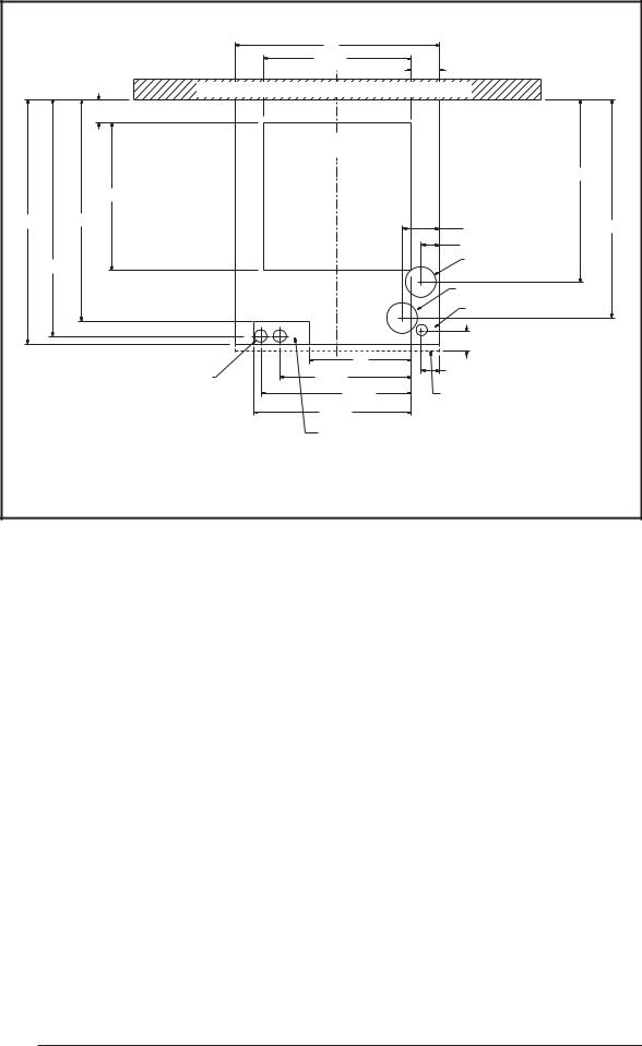
Figure 7. Cut-Out Locations
AIR DISTRIBUTION SYSTEMS
For proper air distribution, the supply duct system must be designed so that the static pressure measured external to the furnace does not exceed the listed static pressure rating shown on the furnace rating plate.
Three typical distribution systems are illustrated in Figure 2. Location, size, and number of registers should be selected on the basis of best air distribution and floor plan of the home.
DUCT CONNECTOR SELECTION
PLATINUM SERIES
a.For Platinum ready construction use the 14” round plenum, p/n: 903896.
NON-PLATINUM SERIES
a.Determine depth of floor cavity from surface of floor to top of supply air duct (See Figure 3).
b.Select appropriate model from Table 5 which matches X-dimension of the floor
10
cavity. To maximize air delivery, remove reducer “C” (see Figure 5) to obtain the largest open area that will fit the duct/floor construction.
DUCT INSTALLATION
Required floor, ceiling, and roof cut-out openings must be carefully located to avoid misalignment of the furnace (see Figures 6 & 7). Installation procedures are suggested for typical furnace installations and need not be followed in the exact listed sequence.
CUT OUT FLOOR OPENING & FUEL LINE HOLE
a.Determine center of closet or alcove (Figures 7 & 8).
b.Locate center of the floor opening, measured 10" from the rear wall, and mark cutout measuring approximately 14-1/2" by 14- 1/2" (± 1”) for model duct connector used (refer to Figures 4 & 5).
c.Locate center of gas line hole, measured 23- 1/4" from the rear wall and 6-5/8" to the left of center of the floor cut-out (See Figure 6) or
5-1/4" to the left of center of the floor cut-out, or for entry through right-side of furnace measured 9" to the right of center of the floor cut-out.
d. Cut out floor opening and one gas line hole.
CUT DUCT OPENING (FINGER TABBED ONLY)
a.Place duct connector through the floor opening with bottom tabs resting on top of the supply air duct.
b.Center duct connector and push back against rear edge of floor opening.
c.Mark cut-out location (tab area) and remove duct connector.
d.Cut out duct opening 1/16" larger than area marked.
INSTALL FURNACE MOUNTING PLATE
a.Place mounting plate (supplied within duct connector) at rear of the floor opening (See Figure 9).
INSTALLING PLATINUM SERIES 14” ROUND DUCT CONNECTOR
a.Place duct connector through the floor opening. (See Figure 9).
b.Secure duct connector to floor.
INSTALLING SCREW DOWN DUCT CONNECTOR
a.Apply a bead of caulking, mastic, or other approved sealant around bottom side of 1/2” flange and restrictor plate, when applicable.
b.Locate the duct connector over duct and carefully lower screw down duct connector into place.
c.Once duct connector is located on duct, temporarily hold in place while fastening duct connector to the floor using flat head screws or nails. Be sure flanges of duct connector stay in contact with the duct.
d.Screw plenum to duct making sure a seal is made between the duct and the duct con-
MOUNTING |
REAR WALL |
PLATE |
|
FLOOR
OPENING
FUEL
LINE
HOLES
SUPPLY AIR DUCT
Figure 8. Mounting Plate
|
|
|
SCREWS |
|
BEND CONNECTOR TABS |
SCREWS |
MOUNTING |
|
|
||
|
UNDER DUCT OPENING |
|
PLATE |
|
|
|
|
MOUNTING |
REAR WALL |
MOUNTING |
|
PLATE |
|
PLATE |
PLENUM |
FLOOR |
|
FLOOR |
|
OPENING |
|
OPENING |
|
|
|
|
|
FUEL |
|
FUEL |
FUEL |
LINE |
|
LINE |
|
|
LINE |
||
HOLES |
|
HOLES |
|
|
HOLES |
||
|
|
|
|
SUPPLY AIR DUCT |
SUPPLY AIR DUCT |
|
|
|
|
|
14” SUPPLY |
|
|
|
CONNECTION |
Finger Tabbed |
Screw Down |
Platinum Series |
|
Duct Connectors |
Duct Connectors |
||
Figure 9. Duct Connector
11
 Loading...