

NordicTrack NTL118062 Owner's Manual
www.nordictrack.com
Model No. NTL11806.2
Serial No.
Write the serial number in the space
above for reference.
Serial Number
Decal
QUESTIONS?
If you have questions, or if parts are
damaged or missing, DO NOT
CONTACT THE STORE; please
contact Customer Care.
USER'S MANUAL
IMPORTANT: You must note the
product model number and serial
number (see the drawing above)
before contacting us:
CALL TOLL-FREE:
1-888-825-2588
Mon.–Fri. 6 a.m.–6 p.m. MT
Sat. 8 a.m.–4 p.m. MT
ON THE WEB:
www.nordictrackservice.com
CAUTION
Read all precautions and instructions in this manual before using
this equipment. Save this manual
for future reference.
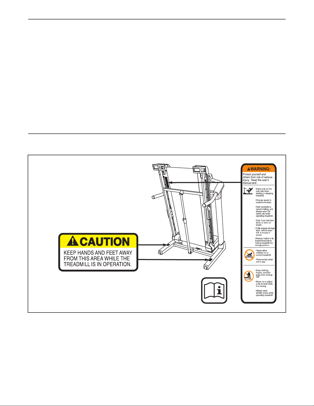
TABLE OF CONTENTS
WARNING DECAL PLACEMENT . . . . . . . . . . . . . . . . . . . . . . . . . . . . . . . . . . . . . . . . . . . . . . . . . . . . . . . . . . . . . .2
IMPORTANT PRECAUTIONS . . . . . . . . . . . . . . . . . . . . . . . . . . . . . . . . . . . . . . . . . . . . . . . . . . . . . . . . . . . . . . . . .3
BEFORE YOU BEGIN . . . . . . . . . . . . . . . . . . . . . . . . . . . . . . . . . . . . . . . . . . . . . . . . . . . . . . . . . . . . . . . . . . . . . . .6
ASSEMBLY . . . . . . . . . . . . . . . . . . . . . . . . . . . . . . . . . . . . . . . . . . . . . . . . . . . . . . . . . . . . . . . . . . . . . . . . . . . . . . .7
OPERATION AND ADJUSTMENT . . . . . . . . . . . . . . . . . . . . . . . . . . . . . . . . . . . . . . . . . . . . . . . . . . . . . . . . . . . .14
HOW TO FOLD AND MOVE THE TREADMILL . . . . . . . . . . . . . . . . . . . . . . . . . . . . . . . . . . . . . . . . . . . . . . . . . .27
TROUBLESHOOTING . . . . . . . . . . . . . . . . . . . . . . . . . . . . . . . . . . . . . . . . . . . . . . . . . . . . . . . . . . . . . . . . . . . . . .29
EXERCISE GUIDELINES . . . . . . . . . . . . . . . . . . . . . . . . . . . . . . . . . . . . . . . . . . . . . . . . . . . . . . . . . . . . . . . . . . .32
PART LIST . . . . . . . . . . . . . . . . . . . . . . . . . . . . . . . . . . . . . . . . . . . . . . . . . . . . . . . . . . . . . . . . . . . . . . . . . . . . . . .34
EXPLODED DRAWING . . . . . . . . . . . . . . . . . . . . . . . . . . . . . . . . . . . . . . . . . . . . . . . . . . . . . . . . . . . . . . . . . . . . .36
ORDERING REPLACEMENT PARTS . . . . . . . . . . . . . . . . . . . . . . . . . . . . . . . . . . . . . . . . . . . . . . . . . .Back Cover
LIMITED WARRANTY . . . . . . . . . . . . . . . . . . . . . . . . . . . . . . . . . . . . . . . . . . . . . . . . . . . . . . . . . . . . . . .Back Cover
WARNING DECAL PLACEMENT
This drawing shows the locations of the
warning decals. If a decal is missing or il-
legible, call the telephone number on the
front cover of this manual and request a
free replacement decal. Apply the decal
in the location shown. Note: The decals
may not be shown at actual size.
NordicTrack is a registered trademark of ICON IP, Inc.
2

IMPORTANT PRECAUTIONS
WARNING: To reduce the risk of serious injury, read all important precautions and in-
structions in this manual and all warnings on your treadmill before using your treadmill. ICON assumes no responsibility for personal injury or property damage sustained by or through the use of
this product.
1. Before beginning this or any exercise program, consult your physician. This is especially important for persons over age 35 or
persons with pre-existing health problems.
2. It is the responsibility of the owner to ensure
that all users of this treadmill are adequately
informed of all warnings and precautions.
3. Use the treadmill only as described.
4. Place the treadmill on a level surface, with at
least 8 ft. (2.4 m) of clearance behind it and 2
ft. (0.6 m) on each side. Do not place the
treadmill on any surface that blocks air openings. To protect the floor or carpet from damage, place a mat under the treadmill.
5. Keep the treadmill indoors, away from moisture and dust. Do not put the treadmill in a
garage or covered patio, or near water.
6. Do not operate the treadmill where aerosol
products are used or where oxygen is being
administered.
11. When connecting the power cord (see page
14), plug the power cord into a surge suppressor (not included) and plug the surge suppressor into a grounded circuit capable of
carrying 15 or more amps. No other appliance
should be on the same circuit. Do not use an
extension cord.
12. Use only a single-outlet surge suppressor that
meets all of the specifications described on
page 14. To purchase a surge suppressor, see
your local NordicTrack dealer or call the telephone number on the front cover of this manual and order part number 146148, or see your
local electronics store.
13. Failure to use a properly functioning surge
suppressor could result in damage to the control system of the treadmill. If the control system is damaged, the walking belt may slow,
accelerate, or stop unexpectedly, which may
result in a fall and serious injury.
14. Keep the power cord and the surge suppressor away from heated surfaces.
7. Keep children under age 12 and pets away
from the treadmill at all times.
8. The treadmill should be used only by persons weighing 350 lbs. (159 kg) or less.
9. Never allow more than one person on the
treadmill at a time.
10. Wear appropriate exercise clothes when
using the treadmill. Do not wear loose
clothes that could become caught in the
treadmill. Athletic support clothes are recommended for both men and women. Always
wear athletic shoes. Never use the treadmill
with bare feet, wearing only stockings, or in
sandals.
15. Never move the walking belt while the power
is turned off. Do not operate the treadmill if
the power cord or plug is damaged, or if the
treadmill is not working properly. (See
TROUBLESHOOTING on page 29 if the treadmill is not working properly.)
16. Read, understand, and test the emergency
stop procedure before using the treadmill (see
HOW TO TURN ON THE POWER on page 16).
17. Never start the treadmill while you are standing on the walking belt. Always hold the
handrails while using the treadmill.
3

8. The treadmill is capable of high speeds.
1
Adjust the speed in small increments to
avoid sudden jumps in speed.
9. The pulse sensor is not a medical device.
1
Various factors, including the user's move-
ent, may affect the accuracy of heart rate
m
readings. The pulse sensor is intended only
as an exercise aid in determining heart rate
trends in general.
20. Never leave the treadmill unattended while it
is running. Always remove the key, unplug
the power cord, and switch the reset/off circuit breaker to the “off” position when the
treadmill is not in use. (See the drawing on
page 6 for the location of the reset/off circuit
breaker.)
21. Do not attempt to raise, lower, or move the
treadmill until it is properly assembled. (See
ASSEMBLY on page 7, and HOW TO FOLD
AND MOVE THE TREADMILL on page 27.) You
must be able to safely lift 45 lbs. (20 kg) to
raise, lower, or move the treadmill.
22. Do not change the incline of the treadmill by
placing objects under the treadmill.
23. When folding or moving the treadmill, make
sure that the storage latch is holding the
frame securely in the storage position.
24. Inspect and properly tighten all parts of the
treadmill regularly.
5. Never insert or drop any object into any
2
opening on the treadmill.
DANGER: Always unplug the power
26.
ord immediately after use, before cleaning
c
the treadmill, and before performing the maintenance and adjustment procedures described in this manual. Never remove the
motor hood unless instructed to do so by an
authorized service representative. Servicing
other than the procedures in this manual
should be performed by an authorized service
representative only.
27. The treadmill is intended for in-home use
only. Do not use the treadmill in any commercial, rental, or institutional setting.
28. To reduce the risk of electric shock, do not re-
move the cover or the back of the television.
There are no user serviceable parts inside.
Refer servicing to qualified service personnel.
29. Upon completion of any service or repairs to
the treadmill or the television, ask the service
technician to perform safety checks to confirm that the unit is in proper operating condition.
Note to CATV system installer: This reminder
is provided to call the CATV system installerʼs
attention to Article 820-40 of the NEC that provides guidelines for proper grounding and, in
particular, specifies that the cable ground
shall be connected to the grounding system
of the building, as close to the point of cable
entry as practical.
4
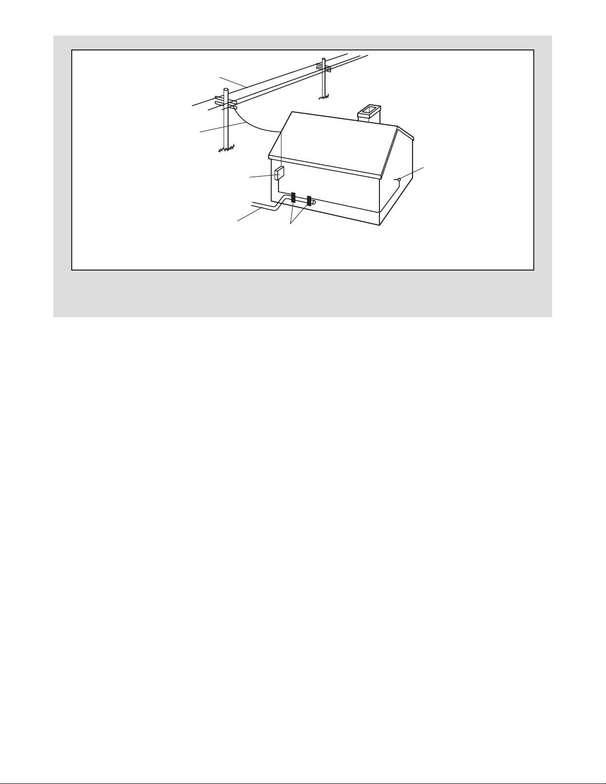
Power Lines
Service
ntrance
E
Conductors
Service
ntrance
E
Equipment
o External Antenna
T
Terminal of Treadmill
Power Service Grounding
Electrode System (e.g.
Interior Metal Water Pipe)
SAVE THESE INSTRUCTIONS
Ground
Clamps
5
BEFORE YOU BEGIN
Thank you for selecting the revolutionary NordicTrack
VIEWPOINT 3000 treadmill. The VIEWPOINT 3000
treadmill offers a selection of features designed to
make your workouts at home more enjoyable and effective. And when youʼre not exercising, the unique
treadmill can be folded up, requiring less than half the
floor space of other treadmills.
For your benefit, read this manual carefully before
using the treadmill. If you have questions after read-
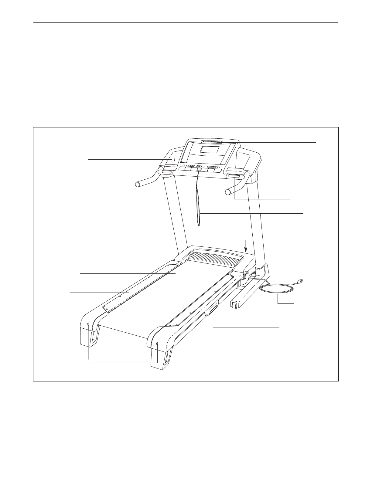
Accessory Tray
Handrail
®
ing this manual, please see the front cover of this manual. To help us assist you, note the product model
number and serial number before contacting us. The
model number and the location of the serial number
decal are shown on the front cover of this manual.
Before reading further, please familiarize yourself with
the parts that are labeled in the drawing below.
Console/Television
Pulse Sensor
Key/Clip
Fan
Walking Belt
Foot Rail
Rear Roller
Adjustment Bolts
Reset/Off
Circuit Breaker
Power Cord
Platform Cushion
6
ASSEMBLY
3/4" Screw (7)–6
1" Tek Screw (82)–8
Extension Leg Bolt (87)–4
5/16" Star
Washer (110)–4
Extension Leg
Nut (91)–4
3/8" Star
Washer (67)–4
Nut (20)–2
Base Cover Screw (63)–4
Console Bolt (72)–4
Latch Bolt (109)–2
ssembly requires two persons. Set the treadmill in a cleared area and remove all packing materials. Do not
A
dispose of the packing materials until assembly is completed.
Note: The underside of the treadmill walking belt is coated with high-performance lubricant. During shipping, a
small amount of lubricant may be transferred to the top of the walking belt or the shipping carton. This is a normal
condition and does not affect treadmill performance. If there is lubricant on top of the walking belt, simply wipe off
the lubricant with a soft cloth and a mild, non-abrasive cleaner.
Assembly requires the included hex key and your own Phillips screwdriver , rubber
mallet and adjustable wrench . Use the drawings below to identify the assembly hard-
ware. The number in parentheses below each drawing is the key number of the part, from the PART LIST near
the end of this manual. The number after the parentheses is the quantity needed for assembly. Note: If a part is
not in the hardware kit, check to see if it is preattached to one of the parts to be assembled. To avoid
damaging plastic parts, do not use power tools for assembly. Extra hardware may be included.
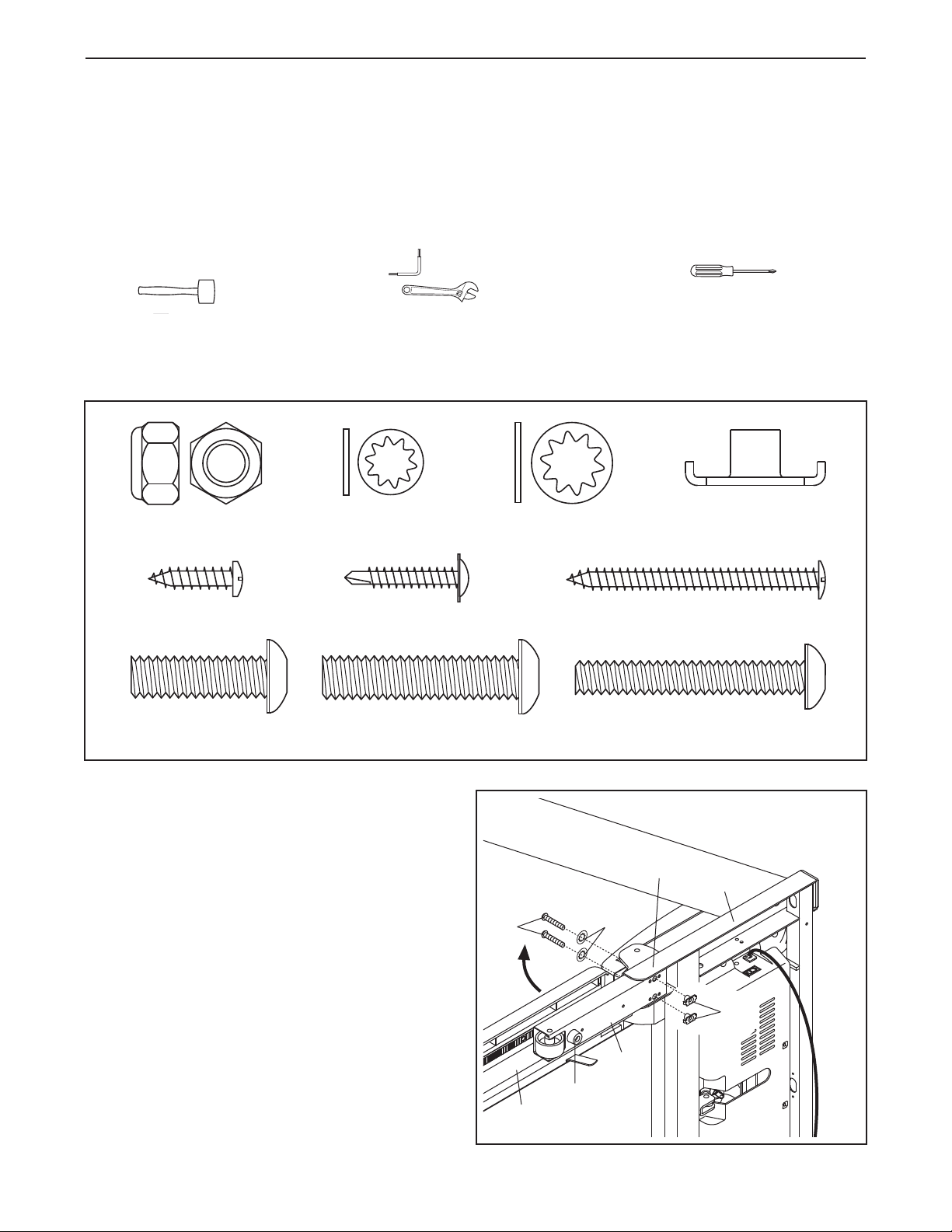
1. Make sure that the power cord is unplugged.
With the help of a second person, carefully tip
the treadmill onto its side as shown. Partially fold
the Frame (55) so that the treadmill is more stable. Do not fully fold the Frame until the
treadmill is completely assembled.
Insert an Extension Leg (97) into the indicated
bracket on the base of the Uprights (85). Make
sure that the Extension Leg is turned so the Base
Pad (81) is on the side shown. If necessary, use
a rubber mallet to align the holes in the
Extension Leg with the holes in the bracket.
Attach the Extension Leg (97) with two Extension
Leg Bolts (87), two 5/16" Star Washers (110),
and two Extension Leg Nuts (91) as shown.
Firmly tighten the Extension Leg Bolts.
1
87
55
7
Bracket
110
97
81
85
91
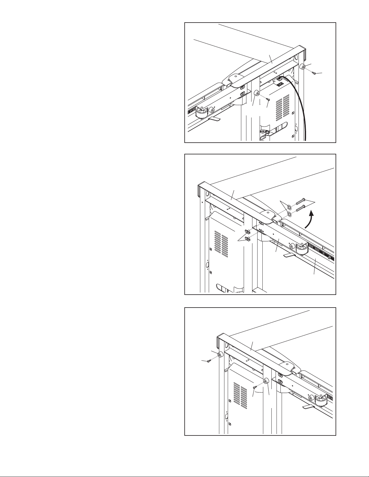
2. Attach two Base Pads (81) to the base of the
Uprights (85) in the indicated locations with two
1" Tek Screws (82). Note: One replacement Base
ad may be included. Use the Base Pad to re-
P
place any Base Pad that becomes worn.
2
85
81
82
81
82
3. With the help of a second person, carefully tip
the treadmill onto its other side as shown.
Partially fold the Frame (55) so that the treadmill
is more stable. Do not fully fold the Frame
until the treadmill is completely assembled.
Insert the other Extension Leg (97) into the indicated bracket on the base of the Uprights (85).
Attach the Extension Leg (97) with two Extension
Leg Bolts (87), two 5/16" Star Washers (110),
and two Extension Leg Nuts (91) as shown.
Firmly tighten the Extension Leg Bolts.
4. Attach two Base Pads (81) to the base of the
Uprights (85) in the indicated locations with two
1" Tek Screws (82).
3
85
110
91
97
4
87
55
With the help of a second person, carefully tip
the treadmill down so that all four Base Pads
(81) are resting on the floor and the Uprights
(85) are in the vertical position.
85
81
82
81
82
8
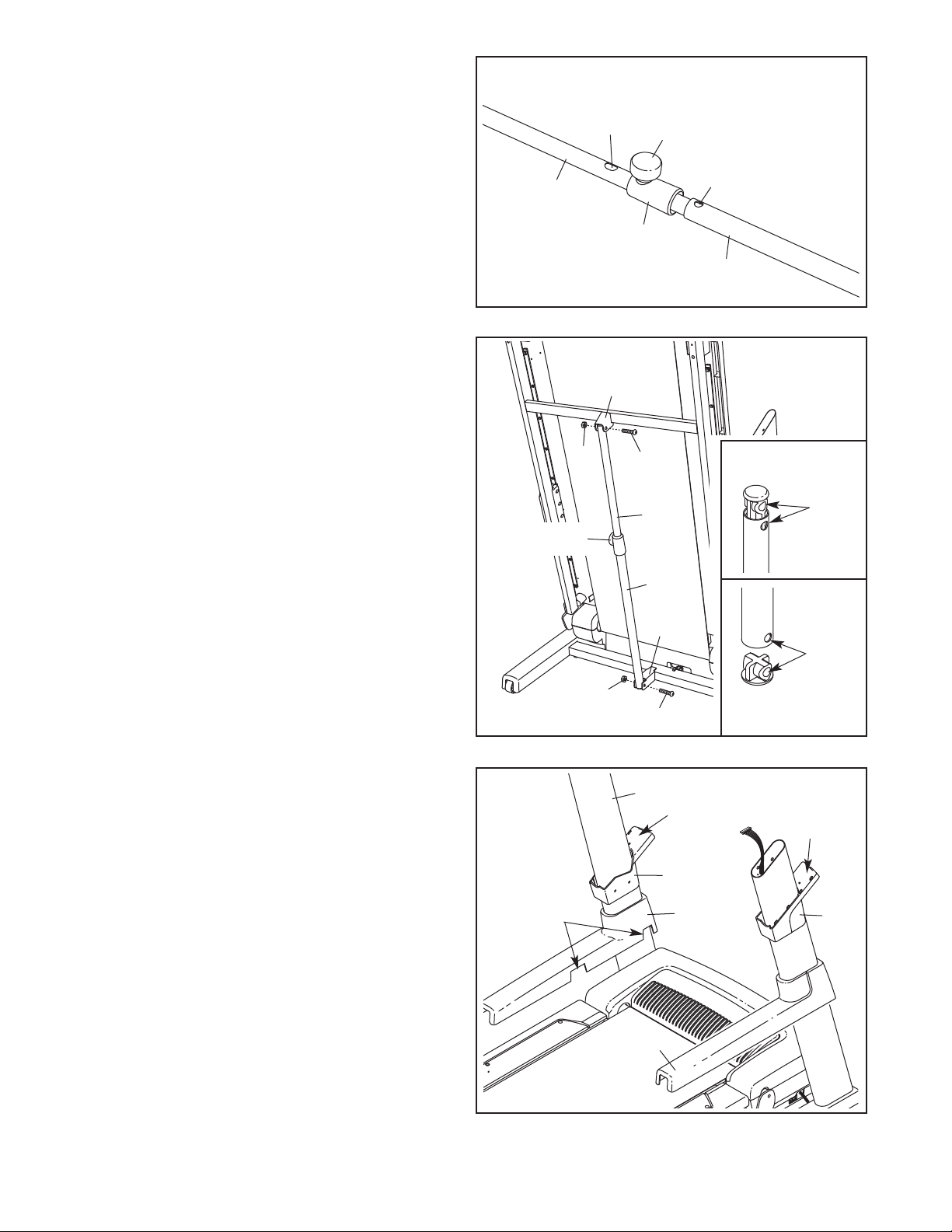
5. Identify the Latch Assembly (76). Make sure that
the sleeve has been slid over hole 1 and that the
latch knob is locked into hole 1. Pull on the
sleeve to make sure that it is locked into
lace.
p
5
Hole 2
Latch Knob
Next, make sure that the latch knob is locked
into hole 2. If it is not, pull out the tube until you
ee hole 2 and then slide the tube back in until
s
the latch knob locks into hole 2.
6. Raise the Frame (55) to the position shown.
Have a second person hold the Frame until this
step is completed.
Remove the plastic ties from the ends of the
Latch Assembly (76). Orient the Latch Assembly
so that the large barrel and the knob are in the
positions shown; make sure that all the holes are
aligned as shown in the inset drawings. Attach
the lower end of the Latch Assembly to the
bracket in the center of the Uprights (85) with a
Latch Bolt (109) and a Nut (20).
Attach the upper end of the Latch Assembly (76)
to the bracket on the Frame (55) with a Latch
Bolt (109) and a Nut (20). Note: It may be necessary to move the Frame back and forth to align
the Latch Assembly with the bracket.
Tube
Sleeve
6
55
20
Knob
109
76
Large
Barrel
85
Hole 1
76
Top
Holes
Holes
Lower the Frame (55) (see HOW TO LOWER
THE TREADMILL FOR USE on page 28).
7. Identify the Left Base Cover (88), which has
cutouts in the locations shown. Slide the Left
Base Cover onto the left Upright (85). Then, slide
the Right Base Cover (86) onto the right Upright.
Identify the Left Upright Sleeve (77) and the Right
Upright Sleeve (9). Slide the Upright Sleeves onto
the Uprights (85) as shown.
7
Cutouts
20
109
85
86
Left
77
88
Bottom
Right
9
9
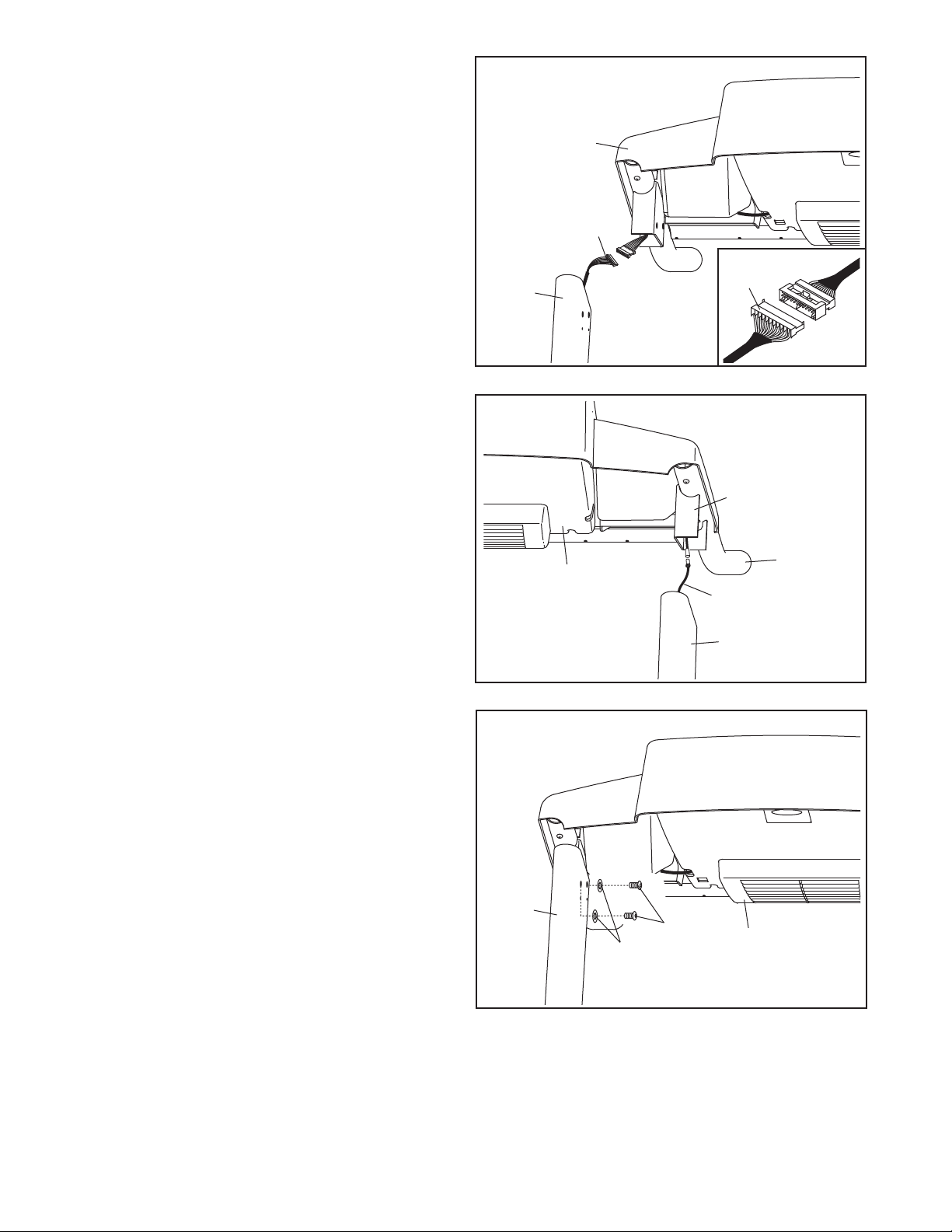
8. Remove the band securing the Upright Wire
Harness (73) to the right Upright (85). Have a
second person hold the console assembly near
the right Upright.
Connect the Upright Wire Harness (73) to the wire
harness on the console assembly. See the inset
drawing. The connectors should slide together easily and snap into place. If they do
not, turn one connector and try again. IF THE
CONNECTORS ARE NOT CONNECTED
PROPERLY, THE CONSOLE MAY BE DAMAGED WHEN THE POWER IS TURNED ON.
Then, insert the connectors into the right Upright
(85).
8
Console
Assembly
85
73
73
9. Remove the band securing the TV Cable (112) to
the left Upright (85). Connect the TV Cable to
the cable extending from the console assembly.
Then, insert the TV Cable into the left Upright.
Next, insert the brackets on the Handrails (70)
into the left Upright (85) and the right Upright
(not shown). Make sure that no wires are
pinched.
10. Attach the console assembly to the Uprights
(85) with four Console Bolts (72) and four 3/8"
Star Washers (67) (only one side is shown).
Start all four Console Bolts and then tighten
them.
9
10
Console
Assembly
Bracket
70
112
85
10
85
67
72
Console
Assembly
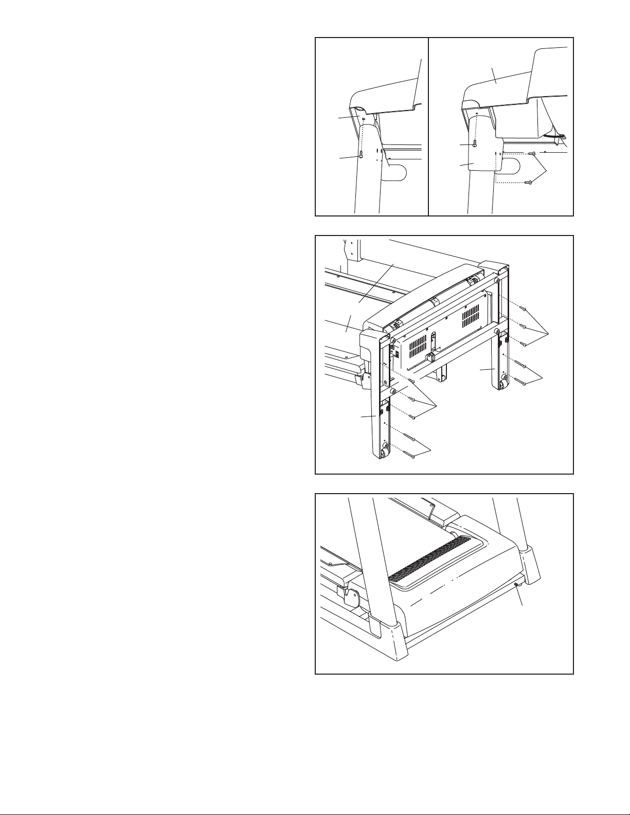
11. See drawing 11a. Remove the indicated 3/4"
Screw (7) from the right Handrail (70).
ee drawing 11b. Slide the Right Upright
S
Sleeve (9) up to the console assembly. Attach
he Right Upright Sleeve with two 1" Tek Screws
t
(82) and the 3/4" Screw (7) you just removed.
11a
70
11b
Console
Assembly
Attach the Left Upright Sleeve (not shown) in the
same way.
12. With the help of a second person, carefully
lower the Uprights (85) to the position shown.
Attach the Right Base Cover (86) with three 3/4"
Screws (7) and two Base Cover Screws (63).
Start all five Screws and then tighten them.
Be careful not to overtighten the Screws.
Attach the Left Base Cover (88) in the same
way.
With the help of a second person, carefully raise
the Uprights (85) to the vertical position.
12
7
7
85
86
9
88
7
82
7
63
63
13. Note the location of the 75 ohm terminal on the
treadmill. For the television to operate, an
audio/video wire must be connected to the
audio/video input jack on the treadmill, a personal audio player must be connected to the
audio jack on the console, or a CATV cable must
be connected to the 75 ohm terminal (see page
13).
14. Make sure that all parts are properly tightened before you use the treadmill. Keep the included hex key
in a secure place. The hex key is used to adjust the walking belt (see page 30). To protect the floor or carpet
from damage, place a mat under the treadmill.
13
75 Ohm
Terminal
11
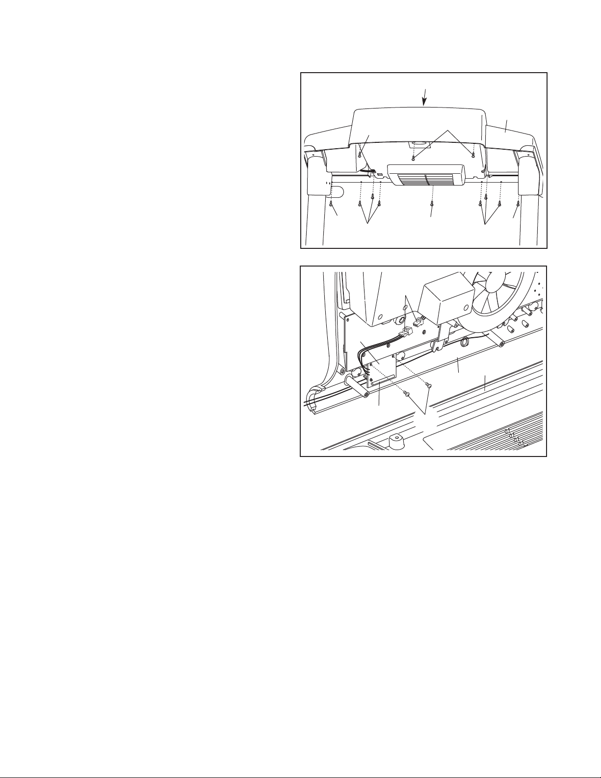
If you purchase the optional chest pulse sensor (see page 26), follow the steps below to install the receiver included with the chest pulse sensor.
1. Make sure that the power cord is unplugged.
Remove the indicated 3/4" Screws (7) from the
back of the Console Base (98).
2. While a second person holds the Console (105),
connect the wire on the receiver (A) to the indicated wire extending from the Console. Next,
hold the receiver so the small cylinder is oriented as shown and is facing away from the
Console. Attach the receiver to the Console in
the location shown with the two included small
screws (B).
1
7
7
2
7
Wires
A
05
1
7
7
98
7
7
3. Make sure that no wires are pinched. See
drawing 1. Reattach the Console (105) to the
Console Base (98) with the 3/4" Screws (7).
Discard the other wires included with the receiver.
Cylinder
105
B
98
12
 Loading...