

NordicTrack GX 4.5 NTEX03912.0, GX 4.5, NTEX03912.0 User Manual
www.nordictrack.com
Model No. NTEX03912.0
Serial No.
Write the serial number in the space
above for reference.
Serial Number
Decal
QUESTIONS?
if you have questions, or if parts
are damaged or missing, DO NOT
CONTACT THE STORE; please
contact Customer Care.
;ER'S A UAL
iMPORTANT: Please register this
product (see the limited warranty
on the back cover of this manual)
before contacting Customer Care.
CALL TOLL-FREE:
1-800-TO-BE-FIT
(1=800=862-3348)
Mon.=Fri. 6 a.m.=6 p.m. MT
Sat. 8 a.m.-4 p.m. MT
ON THE WEB:
www.nordictrackservice.com
[ rn®v",O W',OI
www.iFit.com .-J
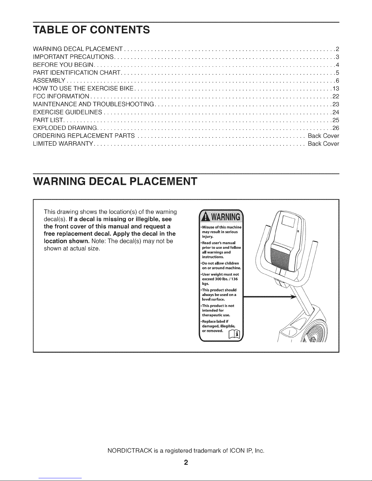
TABLE OF CONTENTS
WARNING DECAL PLACEMENT ............................................................... 2
IMPORTANT PRECAUTIONS .................................................................. 3
BEFORE YOU BEGIN ........................................................................ 4
PART IDENTIFICATION CHART ................................................................ 5
ASSEMBLY ................................................................................ 6
HOW TO USE THE EXERCISE BIKE ........................................................... 13
FCC INFORMATION ........................................................................ 22
MAINTENANCE AND TROUBLESHOOTING ..................................................... 23
EXERCISE GUIDELINES .................................................................... 24
PART LIST ................................................................................ 25
EXPLODED DRAWING ...................................................................... 26
ORDERING REPLACEMENT PARTS .................................................. Back Cover
LIMITED WARRANTY ............................................................... Back Cover
WARNING DECAL PLACEMENT
This drawing shows the location(s) of the warning
decal(s), if a decal is missing or illegible, see
the front cover of this manual and request a
free replacement decal. Apply the decal in the
location shown. Note: The decal(s) may not be
shown at actual size.
•Misuse of this machine
may result in serious
injury,
.Read user's manual
prior to use and follow
a|l warnings and
instructions.
•De not allow children
on or around machine,
•User weight must not
exceed 300 Ibs. / t36
kgs.
•This product should
a|ways be used on a
leve| surface.
•This product is not
intended for
therapeutic use.
•Replace label if
damaged, illegible,
or removed. _l
NORDICTRACK is a registered trademark of ICON IP, Inc.
2
iMPORTANT PRECAUTIONS
WARNING: Toreducetheriskofseriousinjury,reada,importantprecautionsand
instructions in this manual and all warnings on your exercise bike before using your exercise bike.
iCON assumes no responsibility for personal injury or property damage sustained by or through the
use of this product.
1. it is the responsibility of the owner to ensure 8.
that all users of the exercise bike are ade =
quately informed of all precautions.
,
Before beginning any exercise program,
consult your physician. This is especially
important for persons over age 35 or per=
sons with pre=existing health problems.
.
Use the exercise bike only as described in
this manual.
,
The exercise bike is intended for home use
only. Do not use the exercise bike in a com-
mercial, rental, or institutional setting.
,
Keep the exercise bike indoors, away from
moisture and dust. Do not put the exercise
bike in a garage or covered patio, or near
water.
.
Place the exercise bike on a level surface
with at least 2 ft. (0.6 m) of clearance around
the exercise bike. To protect the floor or
carpet from damage, place a mat under the
exercise bike.
Keep children under age 12 and pets away
from the exercise bike at all times.
.
Wear appropriate clothes while exercising;
do not wear loose clothes that could become
caught on the exercise bike. Always wear
athletic shoes for foot protection.
10.
The exercise bike should not be used by
persons weighing more than 300 Ibs.
(136 kg).
11.
The heart rate monitor is not a medical
device. Various factors, including the user's
movement, may affect the accuracy of heart
rate readings. The heart rate monitor is
intended only as an exercise aid in determin-
ing heart rate trends in general.
12.
Always keep your back straight while using
the exercise bike; do not arch your back.
13.
Over exercising may result in serious injury
or death, if you feel faint or if you experience
pain while exercising, stop immediately and
cool down.
7. inspect and properly tighten all parts regu-
larly. Replace any worn parts immediately.
3
BEFORE YOU BEGIN
Thank you for selecting the revolutionary
NORDICTRACK _ GX 4.5 exercise bike. Cycling is an
effective exercise for increasing cardiovascular fitness,
building endurance, and toning the body. The GX 4.5
exercise bike provides an impressive selection of fea-
tures designed to make your workouts at home more
effective and enjoyable.
For your benefit, read this manual carefully before
you use the exercise bike. if you have questions after
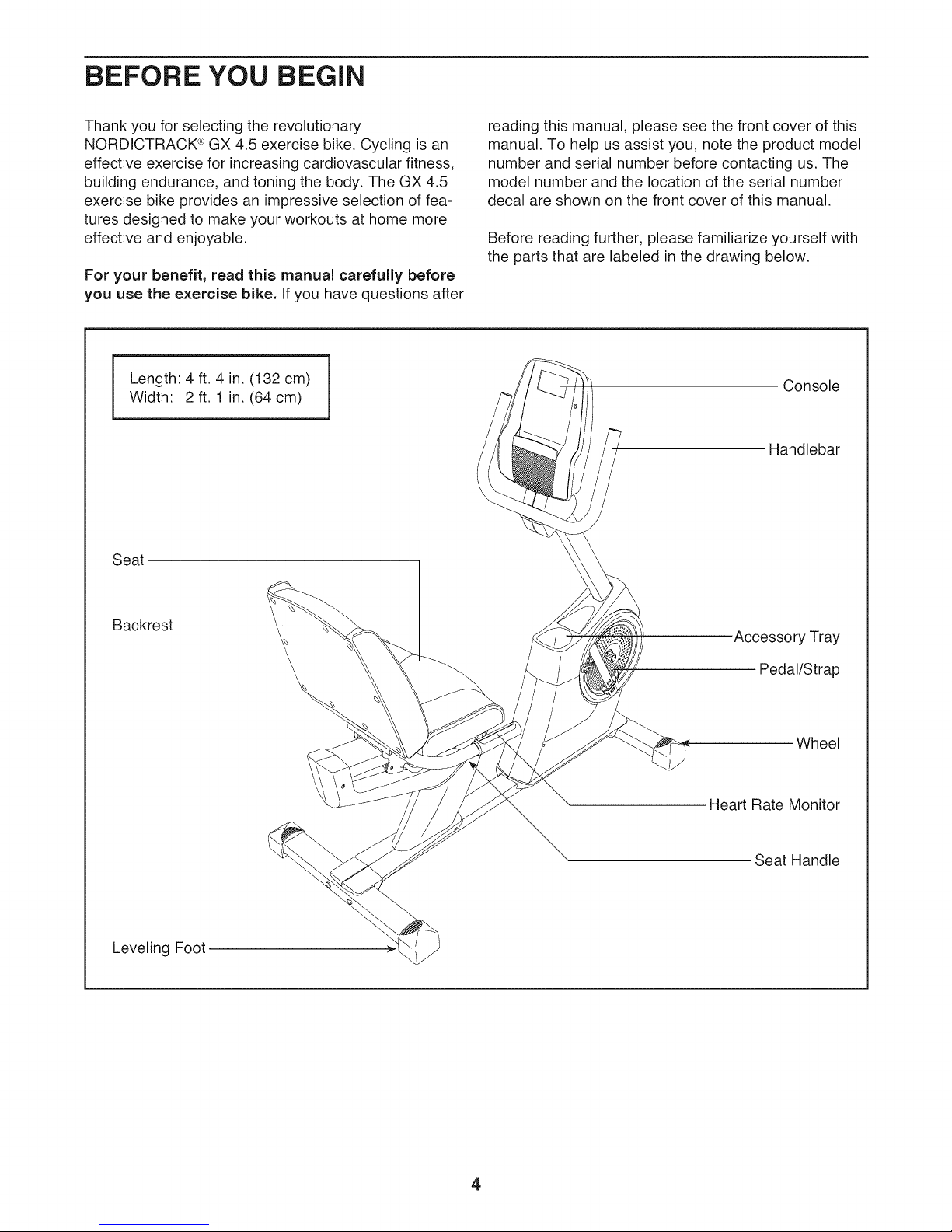
Length: 4 ft. 4 in. (132 cm)
Width: 2 ft. 1 in. (64 cm)
Seat
reading this manual, please see the front cover of this
manual. To help us assist you, note the product model
number and serial number before contacting us. The
model number and the location of the serial number
decal are shown on the front cover of this manual.
Before reading further, please familiarize yourself with
the parts that are labeled in the drawing below.
Console
Handlebar
Backrest
Leveling Foot
Accessory Tray
Pedal/Strap
Wheel
Heart Rate Monitor
Seat Handle
4
PART iDENTiFiCATiON CHART
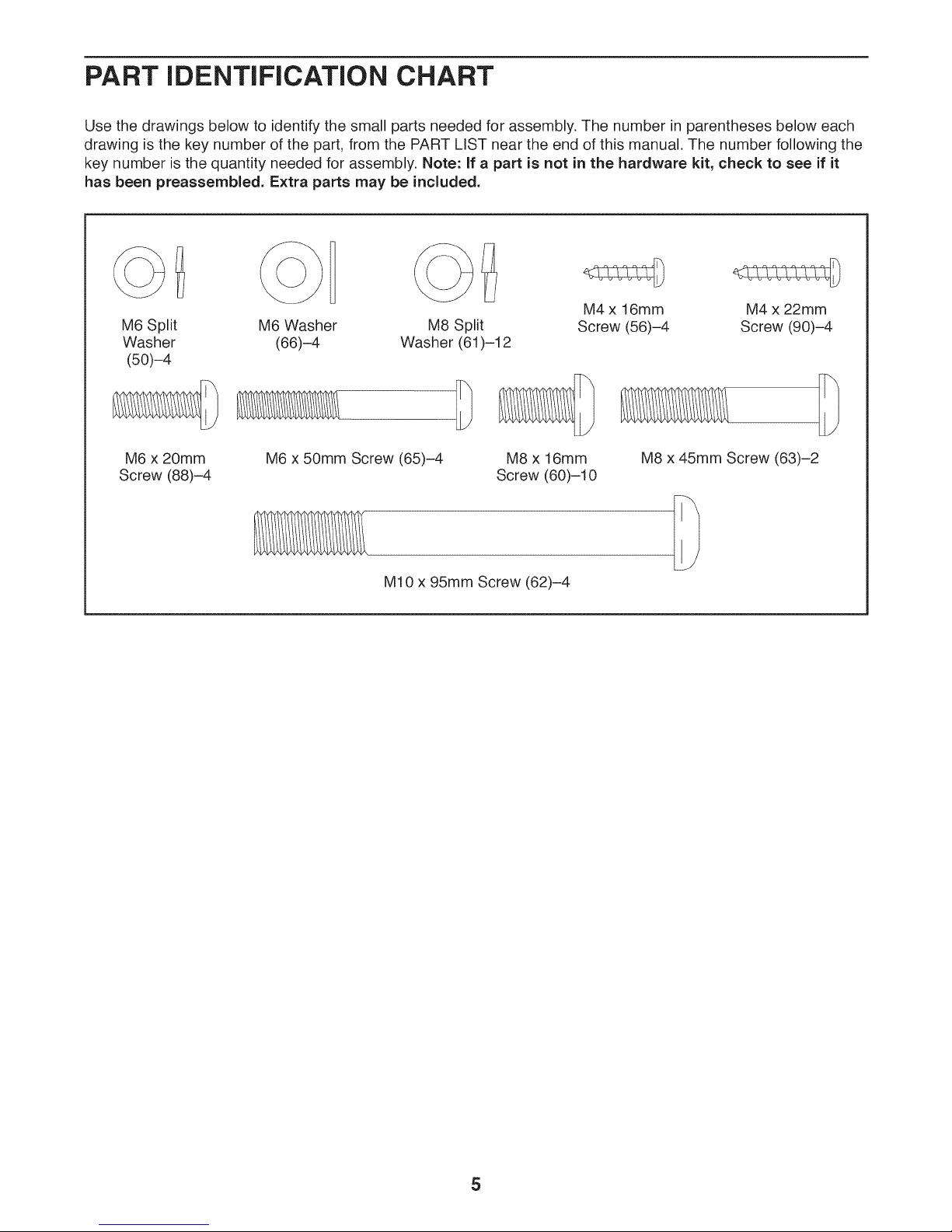
Use the drawings below to identify the small parts needed for assembly. The number in parentheses below each
drawing is the key number of the part, from the PART LIST near the end of this manual. The number following the
key number is the quantity needed for assembly. Note: If a part is not in the hardware kit, check to see if it
has been preassembled. Extra parts may be included.
M4 x 16mm M4 x 22mm
M6 Split
Washer
(50)-4
M6 Washer
(66)-4
M8 Split Screw (56)-4 Screw (90)-4
Washer (61)-12
M6 x 20mm
Screw (88)-4
M6 x 50mm Screw (65)-4
M10 x 95mm Screw (62)-4
M8 x 16mm
Screw (60)-10
M8 x 45mm Screw (63)-2
5
ASSEMBLY
To watch an assembly
video, go to
http ://productvideo.co/
assembly/nordictrack or
use your mobile phone
or smartphone to read
the QR code at the right.
Assembly requires two
persons.
Place all parts in a cleared area and remove the
packing materials. Do not dispose of the packing
materials until you finish all assembly steps.
.
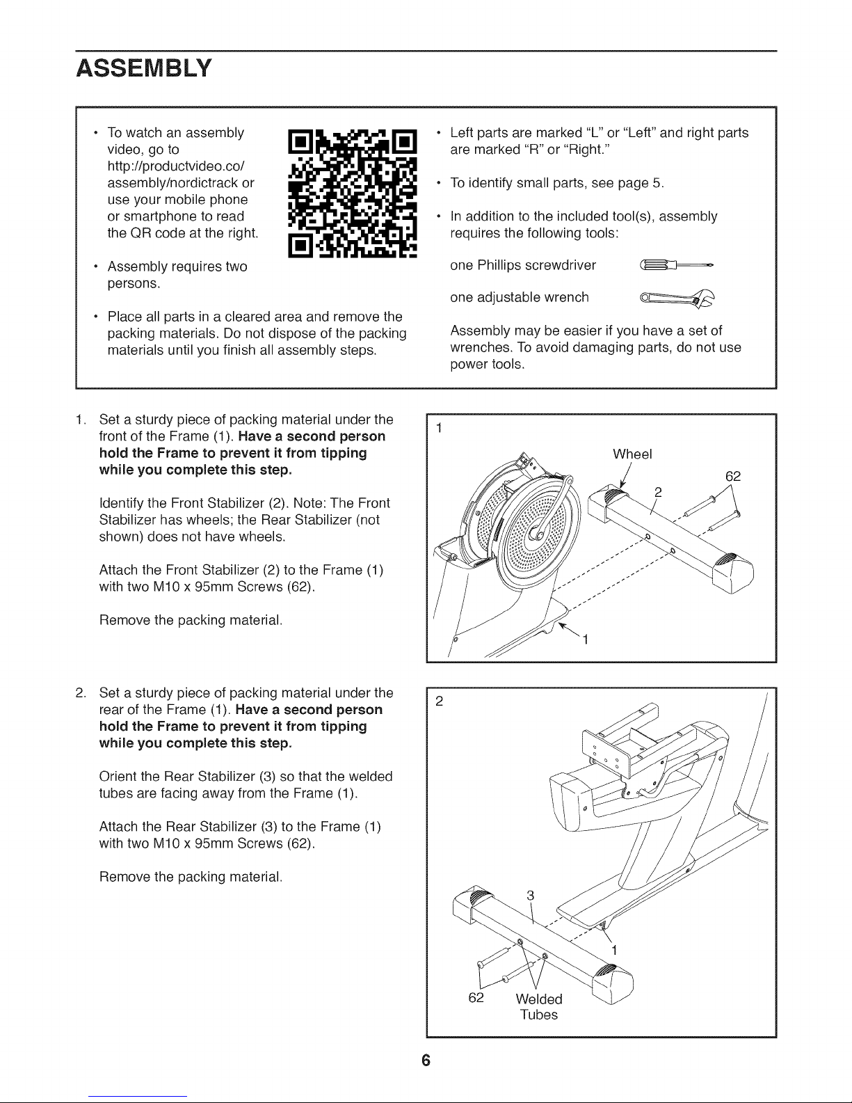
Set a sturdy piece of packing material under the
front of the Frame (1). Have a second person
hold the Frame to prevent it from tipping
while you complete this step.
Identify the Front Stabilizer (2). Note: The Front
Stabilizer has wheels; the Rear Stabilizer (not
shown) does not have wheels.
Left parts are marked "L" or "Left" and right parts
are marked "R" or "Right."
To identify small parts, see page 5.
In addition to the included tool(s), assembly
requires the following tools:
one Phillips screwdriver (]_=====_
one adjustable wrench
Assembly may be easier if you have a set of
wrenches. To avoid damaging parts, do not use
power tools.
Wheel
Attach the Front Stabilizer (2) to the Frame (1)
with two M10 x 95mm Screws (62).
Remove the packing material.
.
Set a sturdy piece of packing material under the
rear of the Frame (1). Have a second person
hold the Frame to prevent it from tipping
while you complete this step.
Orient the Rear Stabilizer (3) so that the welded
tubes are facing away from the Frame (1).
Attach the Rear Stabilizer (3) to the Frame (1)
with two M10 x 95mm Screws (62).
Remove the packing material.
1
62
Welded
Tubes
6
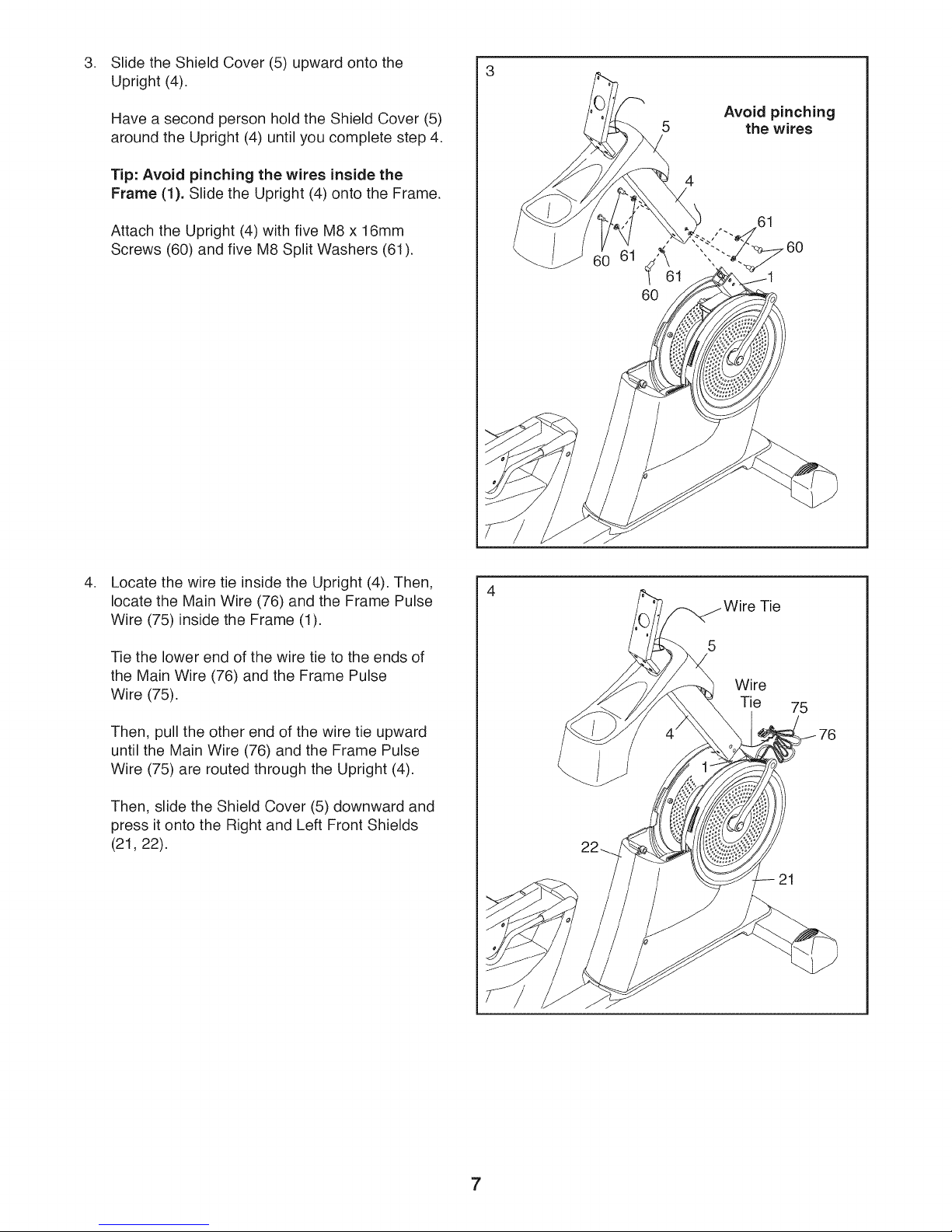
Slide the Shield Cover (5) upward onto the
Upright (4).
Have a second person hold the Shield Cover (5)
around the Upright (4) until you complete step 4.
Tip: Avoid pinching the wires inside the
Frame (1). Slide the Upright (4) onto the Frame.
Attach the Upright (4) with five M8 x 16mm
Screws (60) and five M8 Split Washers (61).
60
5
the wires
4
Avoid pinching
.
Locate the wire tie inside the Upright (4). Then,
locate the Main Wire (76) and the Frame Pulse
Wire (75) inside the Frame (1).
Tie the lower end of the wire tie to the ends of
the Main Wire (76) and the Frame Pulse
Wire (75).
Then, pull the other end of the wire tie upward
until the Main Wire (76) and the Frame Pulse
Wire (75) are routed through the Upright (4).
Then, slide the Shield Cover (5) downward and
press it onto the Right and Left Front Shields
(21, 22).
Tie
5
Wire
Tie
75
7
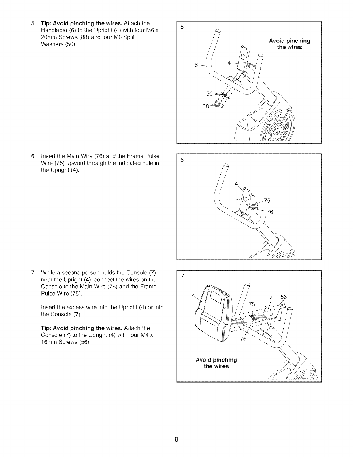
Tip: Avoid pinching the wires. Attach the
5. 5
Handlebar (6) to the Upright (4) with four M6 x
20mm Screws (88) and four M6 Split
Washers (50).
,
Insert the Main Wire (76) and the Frame Pulse
Wire (75) upward through the indicated hole in
the Upright (4).
Avoid pinching
the wires
,
While a second person holds the Console (7)
near the Upright (4), connect the wires on the
Console to the Main Wire (76) and the Frame
Pulse Wire (75).
Insert the excess wire into the Upright (4) or into
the Console (7).
Tip: Avoid pinching the wires. Attach the
Console (7) to the Upright (4) with four M4 x
16mm Screws (56).
4 56
76
Avoid pinching
the wires
8
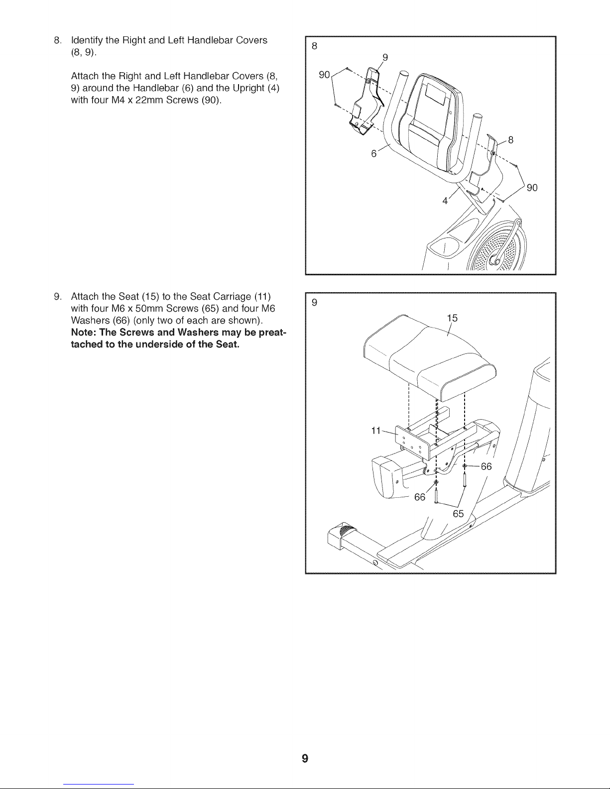
Identify the Right and Left Handlebar Covers
8. 8
(8, 9).
Attach the Right and Left Handlebar Covers (8,
9) around the Handlebar (6) and the Upright (4)
with four M4 x 22mm Screws (90).
.
Attach the Seat (15) to the Seat Carriage (11)
with four M6 x 50mm Screws (65) and four M6
Washers (66) (only two of each are shown).
Note: The Screws and Washers may be preat=
tached to the underside of the Seat.
15
9
 Loading...