

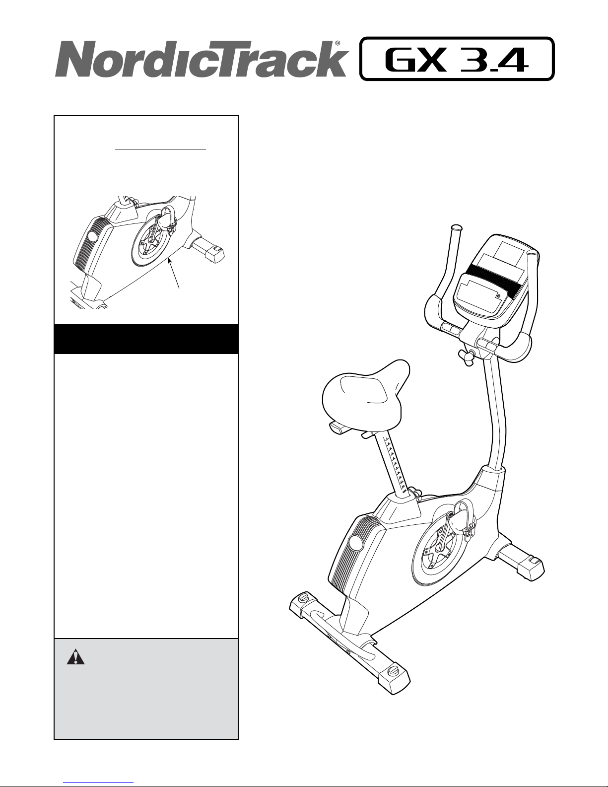
Model No. NTEVEX78612.0
Serial No.
Write the serial number in the space
above for reference.
Serial Number Decal
(under frame)
CUSTOMER SERVICE
UNITED KINGDOM
Call: 08457 089 009
From Ireland: 053 92 36102
Website: www.iconsupport.eu
E-mail: csuk@iconeurope.com
Write:
ICON Health & Fitness, Ltd.
c/o HI Group PLC
Express Way
CASTLEFORD
WF10 5QJ
UNITED KINGDOM
USER’S MANUAL
AUSTRALIA
Call: 1800 993 770
E-mail: australiacc@iconfitness.com
Write:
ICON Health & Fitness
PO Box 635
WINSTON HILLS NSW 2153
AUSTRALIA
CAUTION
Read all precautions and instructions in this manual before using
this equipment. Keep this manual
for future reference.
www.iconeurope.com
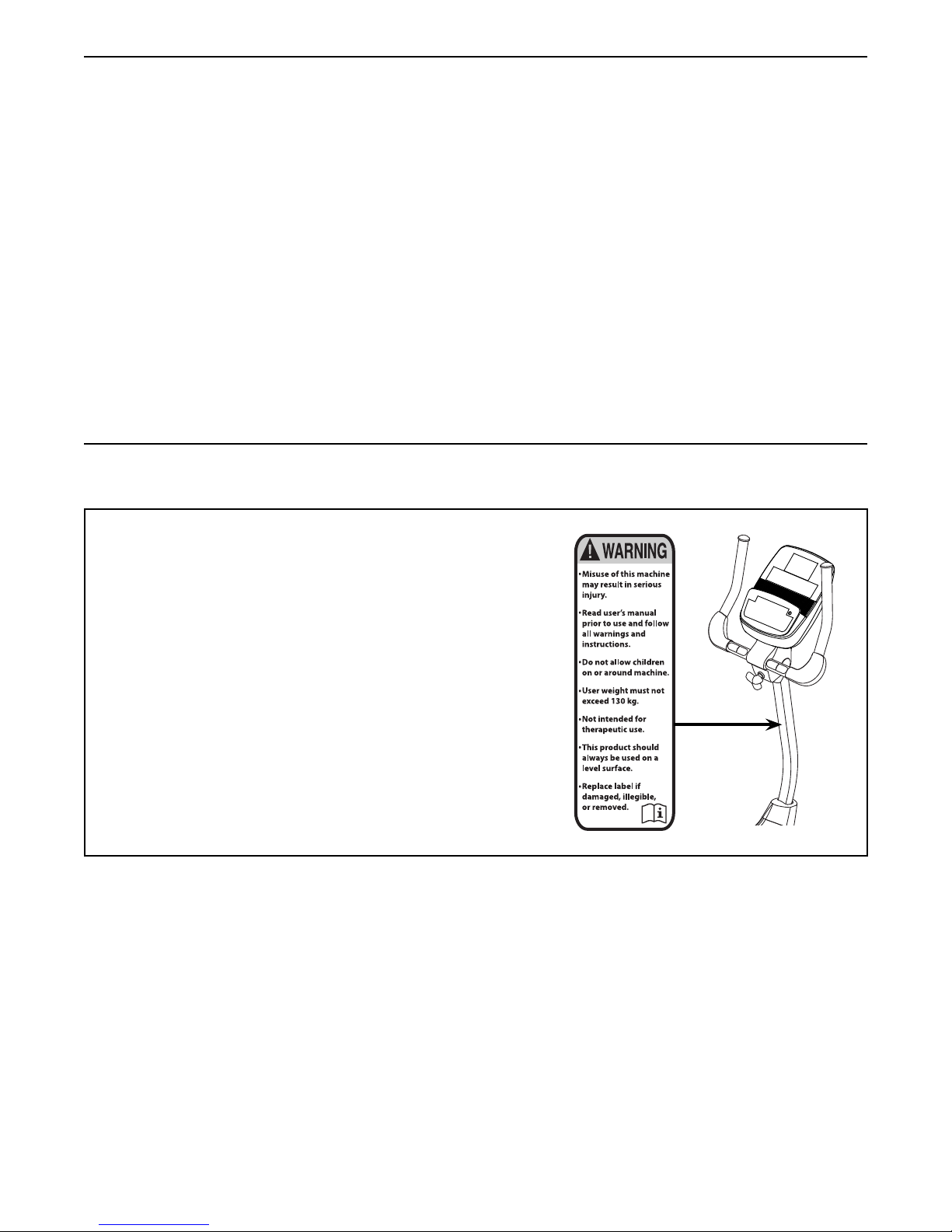
TABLE OF CONTENTS
WARNING DECAL PLACEMENT . . . . . . . . . . . . . . . . . . . . . . . . . . . . . . . . . . . . . . . . . . . . . . . . . . . . . . . . . . . . . . .2
IMPORTANT PRECAUTIONS ..................................................................3
BEFORE YOU BEGIN. . . . . . . . . . . . . . . . . . . . . . . . . . . . . . . . . . . . . . . . . . . . . . . . . . . . . . . . . . . . . . . . . . . . . . . .4
PART IDENTIFICATION CHART. . . . . . . . . . . . . . . . . . . . . . . . . . . . . . . . . . . . . . . . . . . . . . . . . . . . . . . . . . . . . . . .5
ASSEMBLY . . . . . . . . . . . . . . . . . . . . . . . . . . . . . . . . . . . . . . . . . . . . . . . . . . . . . . . . . . . . . . . . . . . . . . . . . . . . . . . .6
THE CHEST HEART RATE MONITOR. . . . . . . . . . . . . . . . . . . . . . . . . . . . . . . . . . . . . . . . . . . . . . . . . . . . . . . . . .12
HOW TO USE THE EXERCISE BIKE. . . . . . . . . . . . . . . . . . . . . . . . . . . . . . . . . . . . . . . . . . . . . . . . . . . . . . . . . . . 13
MAINTENANCE AND TROUBLESHOOTING .....................................................25
EXERCISE GUIDELINES ....................................................................27
PART LIST. . . . . . . . . . . . . . . . . . . . . . . . . . . . . . . . . . . . . . . . . . . . . . . . . . . . . . . . . . . . . . . . . . . . . . . . . . . . . . . .29
EXPLODED DRAWING. . . . . . . . . . . . . . . . . . . . . . . . . . . . . . . . . . . . . . . . . . . . . . . . . . . . . . . . . . . . . . . . . . . . . .31
ORDERING REPLACEMENT PARTS .................................................. Back Cover
RECYCLING INFORMATION ......................................................... Back Cover
WARNING DECAL PLACEMENT
This drawing shows the location(s) of the warning decal(s).
If a decal is missing or illegible, see the front cover
of this manual and request a free replacement decal.
Apply the decal in the location shown. Note: The
decal(s) may not be shown at actual size.
NORDICTRACK is a registered trademark of ICON IP, Inc.
2

IMPORTANT PRECAUTIONS
WARNING: To reduce the risk of serious injury, read all important precautions and
instructions in this manual and all warnings on your exercise bike before using your exercise bike.
ICON assumes no responsibility for personal injury or property damage sustained by or through the
use of this product.
1. It is the responsibility of the owner to ensure
that all users of the exercise bike are adequately informed of all precautions.
2. Before beginning any exercise program,
consult your physician. This is especially
important for persons over age 35 or persons with pre-existing health problems.
3. Use the exercise bike only as described in
this manual.
4. The exercise bike is intended for home use
only. Do not use the exercise bike in a commercial, rental, or institutional setting.
5. Keep the exercise bike indoors, away from
moisture and dust. Do not put the exercise
bike in a garage or covered patio, or near
water.
6. Place the exercise bike on a level surface
with at least 2 ft. (0.6 m) of clearance around
the exercise bike. To protect the floor or
carpet from damage, place a mat under the
exercise bike.
7. Inspect and properly tighten all parts regularly. Replace any worn parts immediately.
8. Keep children under age 12 and pets away
from the exercise bike at all times.
9. Wear appropriate clothes while exercising;
do not wear loose clothes that could become
caught on the exercise bike. Always wear
athletic shoes for foot protection.
10. The exercise bike should not be used by
persons weighing more than 286 lbs.
(130 kg).
11. Be careful when mounting and dismounting
the exercise bike.
12. The heart rate monitor is not a medical
device. Various factors, including the user’s
movement, may affect the accuracy of heart
rate readings. The heart rate monitor is
intended only as an exercise aid in determining heart rate trends in general.
13. Always keep your back straight while using
the exercise bike; do not arch your back.
14. Over exercising may result in serious injury
or death. If you feel faint or if you experience
pain while exercising, stop immediately and
cool down.
3
BEFORE YOU BEGIN
Thank you for selecting the revolutionary
NORDICTRACK® GX 3.4 exercise bike. Cycling is an
effective exercise for increasing cardiovascular fitness,
building endurance, and toning the body. The GX 3.4
exercise bike provides an impressive selection of features designed to make your workouts at home more
effective and enjoyable.
For your benefit, read this manual carefully before
you use the exercise bike. If you have questions after
Length: 3 ft. 5 in. (104 cm)
Width: 1 ft. 11 in. (58 cm)
Heart Rate Monitor
reading this manual, please see the front cover of this
manual. To help us assist you, note the product model
number and serial number before contacting us. The
model number and the location of the serial number
decal are shown on the front cover of this manual.
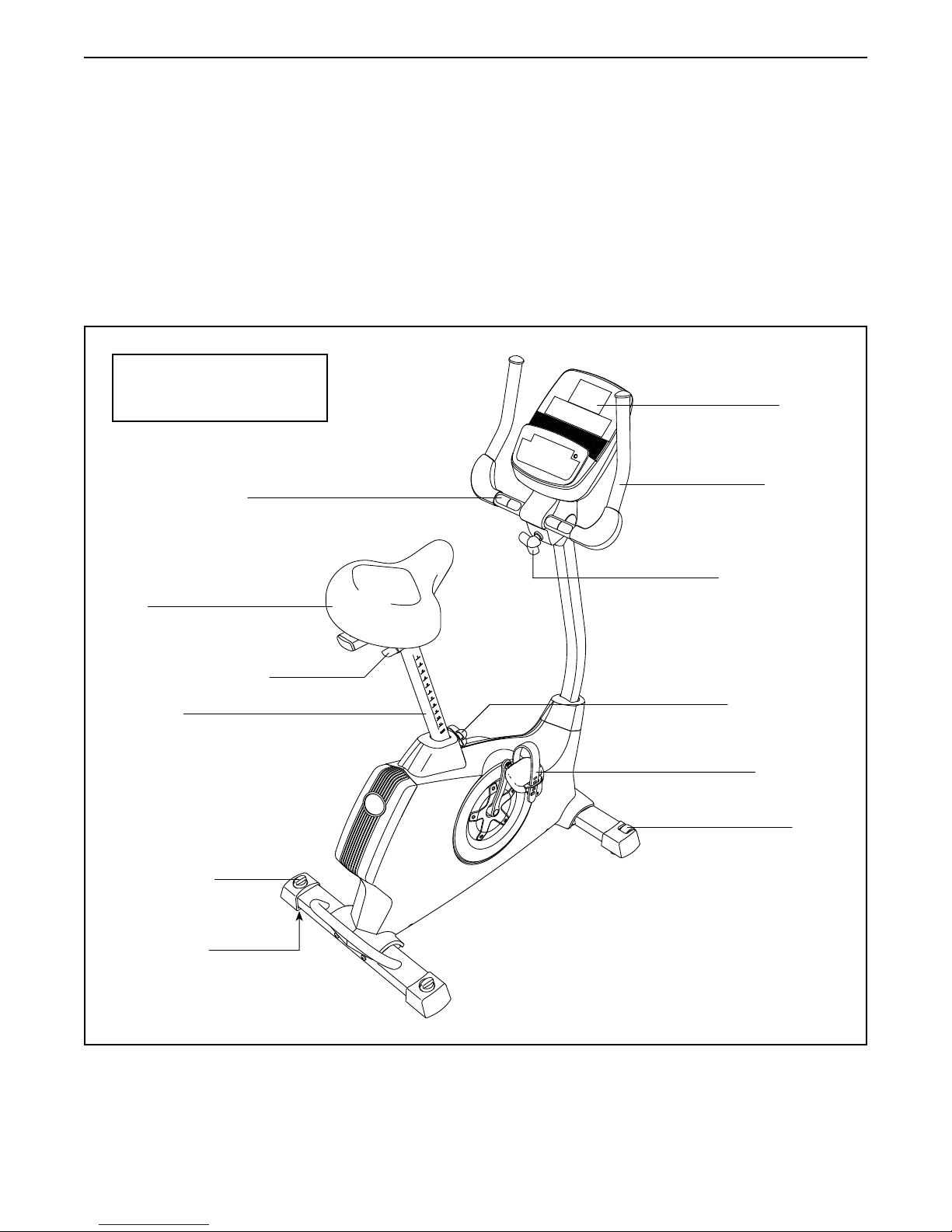
Before reading further, please familiarize yourself with
the parts that are labeled in the drawing below.
Console
Handlebar
Seat
Seat Adjustment Knob
Seat Post
Leveling Knob
Leveling Foot
Adjustment Knob
Seat Post Knob
Pedal/Strap
Wheel
4
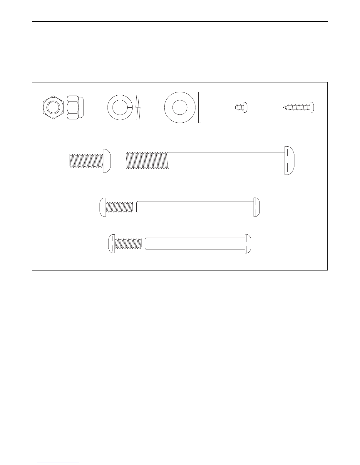
PART IDENTIFICATION CHART
Use the drawings below to identify small parts used in assembly. The number in parentheses by each drawing is
the key number of the part, from the PART LIST near the end of this manual. The number following the key number is the quantity needed for assembly. Note: If a part is not in the hardware kit, check to see if it has been
preattached.
M8 Locknut
(72)–4
M8 x 20mm
Screw (74)–4
M8 Split
Washer (75)–8
M8 Washer
(43)–2
M10 x 95mm
Screw (76)–4
M6 x 70mm Bolt Set (50)–1
M6 x 60mm Bolt Set (51)–1
M4 x 5mm
Bright Screw
(91)–1
M4 x 16mm
Screw (90)–8
5
ASSEMBLY
• Assembly requires two persons.
• Place all parts in a cleared area and remove the
packing materials. Do not dispose of the packing
materials until you complete all assembly steps.
• Left parts are marked “L” or “Left” and right parts
are marked “R” or “Right.”
• To identify small parts, see page 5.
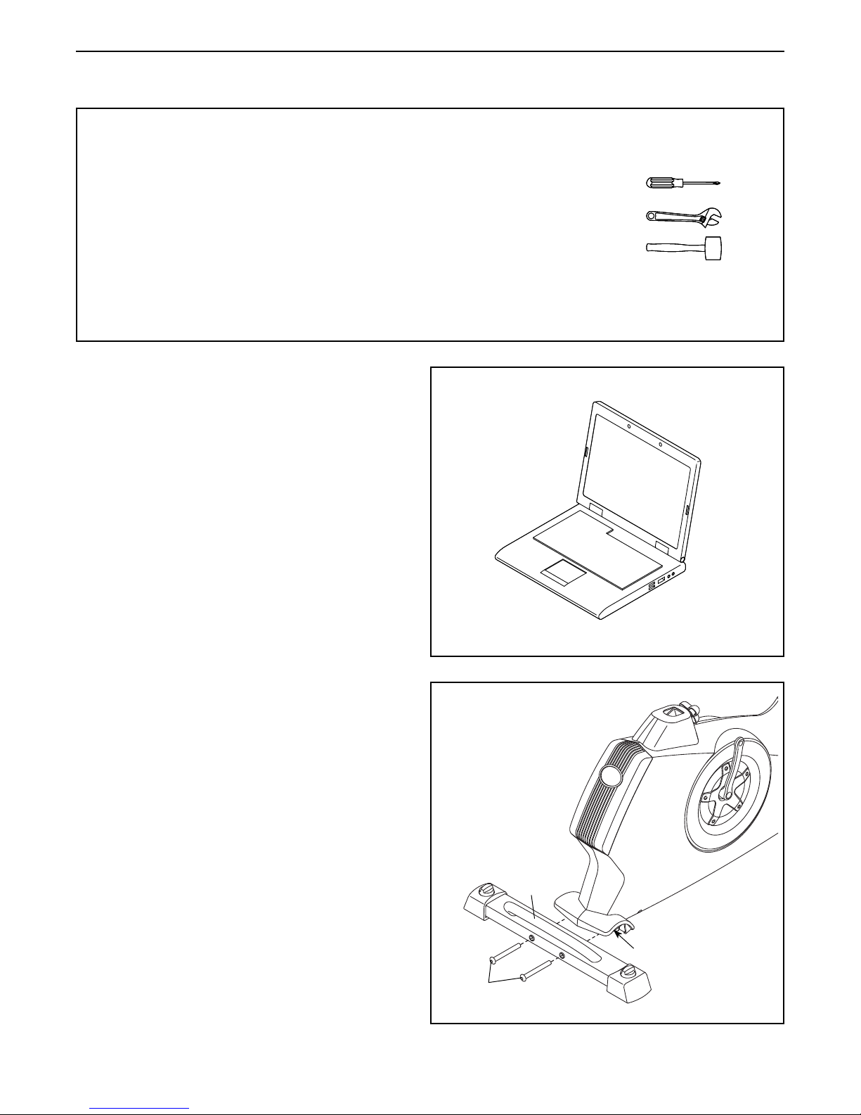
1. Go to www.iconsupport.eu on your computer
and register your product.
• activatesyourwarranty
• savesyoutimeifyoueverneedtocontact
Customer Service
• allowsustonotifyyouofupgradesandoffers
Note: If you do not have Internet access, call
Customer Service (see the front cover of this
manual) and register your product.
• In addition to the included tool(s), assembly
requires the following tools:
one Phillips screwdriver
one adjustable wrench
one rubber mallet
Assembly may be easier if you have a set of
wrenches. To avoid damaging parts, do not use
power tools.
1
2. Attach the Rear Stabilizer (3) to the Frame (1)
with two M10 x 95mm Screws (76).
2
3
1
76
6
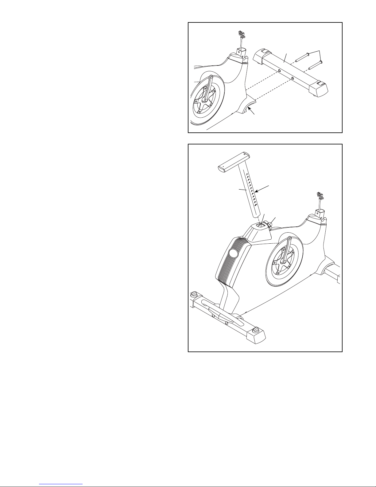
3. Attach the Front Stabilizer (2) to the Frame (1)
with two M10 x 95mm Screws (76).
3
4. Loosen the Adjustment Knob (27) in the Frame
(1) a few turns.
Orient the Seat Post (6) as shown. Then, pull
the Adjustment Knob (27) outward and insert the
Seat Post into the Frame (1).
Slide the Seat Post (6) upward or downward to
the desired position, and release the Adjustment
Knob (27).
2
1
4
Adjustment
1
Holes
27
6
76
Move the Seat Post (6) upward or downward
slightly to make sure that the Adjustment
Knob (27) is engaged in one of the adjustment holes in the Seat Post. Then, tighten the
Adjustment Knob.
7
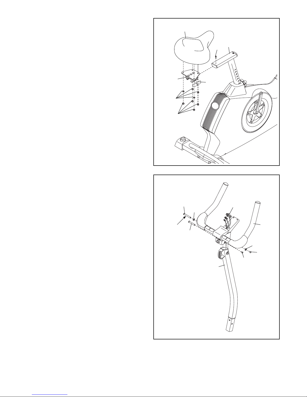
5. Orient the Seat (23) and the Seat Carriage (24)
as shown.
Attach the Seat (23) to the Seat Carriage (24)
with four M8 Locknuts (72) and four M8 Split
Washers (75).
Slide the Seat Carriage (24) onto the Seat
Post (6). Then, slide the Seat Carriage all the
way forward and tighten the Seat Adjustment
Knob (26).
Attach an M4 x 5mm Bright Screw (91) to the
rear of the Seat Post (6).
5
23
6
91
24
75
72
26
6. Using a plastic bag to keep your fingers clean,
apply some of the included grease to an M6 x
70mm Bolt Set (50).
Orient the Handlebar (5) and the Upright (4) as
shown.
While a second person holds the Handlebar (5)
near the Upright (4), insert the Upper Wire (59)
upward through the Handlebar.
Tip: Avoid pinching the Upper Wire (59).
Attach the Handlebar (5) to the Upright (4)
with the M6 x 70mm Bolt Set (50) and two M8
Washers (43).
Then, attach an M6 x 60mm Bolt Set (51)
through the lower bracket on the Handlebar (5).
6
50
43
Grease
51
Avoid pinching the
Upper Wire (59)
59
5
43
50
51
4
8
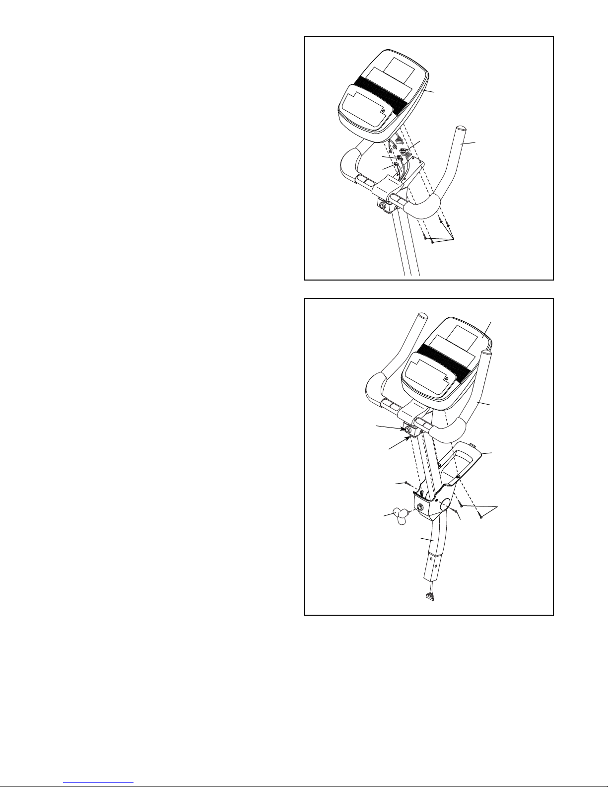
7. While another person holds the Console (13)
near the Handlebar (5), connect the wires on the
Console to the Upper Wire (59), the Pulse Wire
(61), and the Receiver Wire (16).
Insert the excess wire into the Handlebar (5).
Tip: Avoid pinching the wires. Attach the
Console (13) to the Handlebar (5) with four M4 x
16mm Screws (90).
7
13
Avoid pinching
the wires
59
61
16
5
90
8. Orient the Upright (4) assembly and the Pivot
Cover (12) as shown.
Slide the Pivot Cover (12) upward to the
Handlebar (5). Tip: Bend and flex the Pivot
Cover slightly to slide it over the Handlebar.
Attach the Pivot Cover (12) to the Handlebar
(5) and the Console (13) with four M4 x 16mm
Screws (90).
Pivot the Handlebar (5) until the hole in the
Handlebar is aligned with an adjustment hole in
the Upright (4).
Tighten an Adjustment Knob (27) into the
Handlebar (5) and an adjustment hole in the
Upright (4). Make sure that the Adjustment
Knob is engaged in one of the adjustment
holes.
8
Hole
Adjustment
Holes
27
13
5
12
90
90
90
4
9
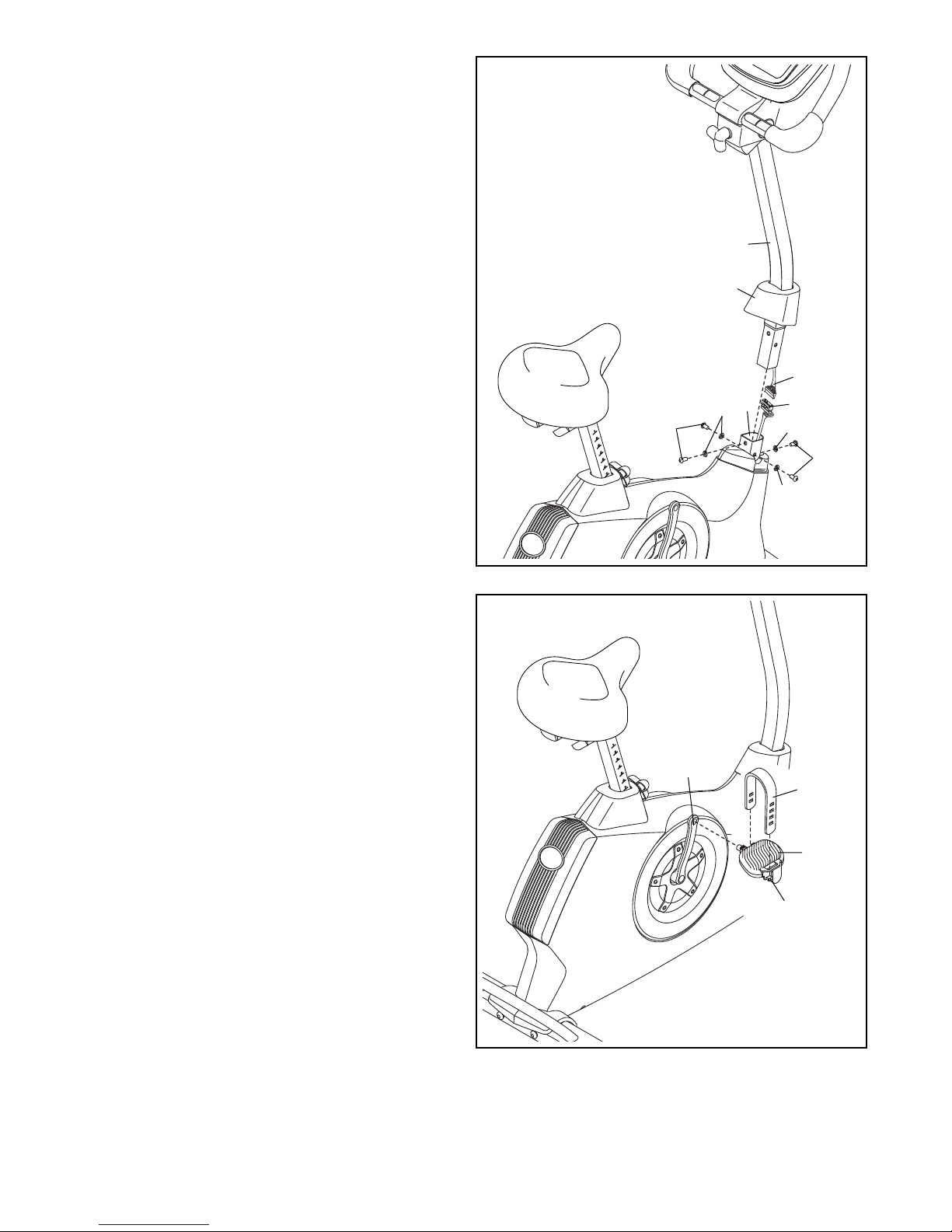
9. Slide the Front Shield Cover (7) upward onto the
Upright (4).
While another person holds the Upright (4) near
the Frame (1), connect the Upper Wire (59) to
the Lower Wire (58).
Insert the Upright (4) into the Frame (1).
Tip: Avoid pinching the wires. Attach the
Upright (4) with four M8 x 20mm Screws (74)
and four M8 Split Washers (75).
Slide the Front Shield Cover (7) downward to the
Frame (1) and press it into place.
9
Avoid pinching
the wires
4
7
59
10. Identify the Right Pedal (21).
Using an adjustable wrench, firmly tighten the
Right Pedal (21) clockwise into the Right Crank
Arm (19).
Tighten the Left Pedal (not shown) counter-
clockwise into the Left Crank Arm (not shown).
Adjust the strap on the Right Pedal (21) to the
desired position, and press the ends of the
straps onto the tabs on the Right Pedal.
Adjust the strap on the Left Pedal (not
shown) in the same way.
10
74
19
75
1
58
75
74
75
Strap
21
Tab
10
 Loading...