

Page 1
www.nordictrack.com
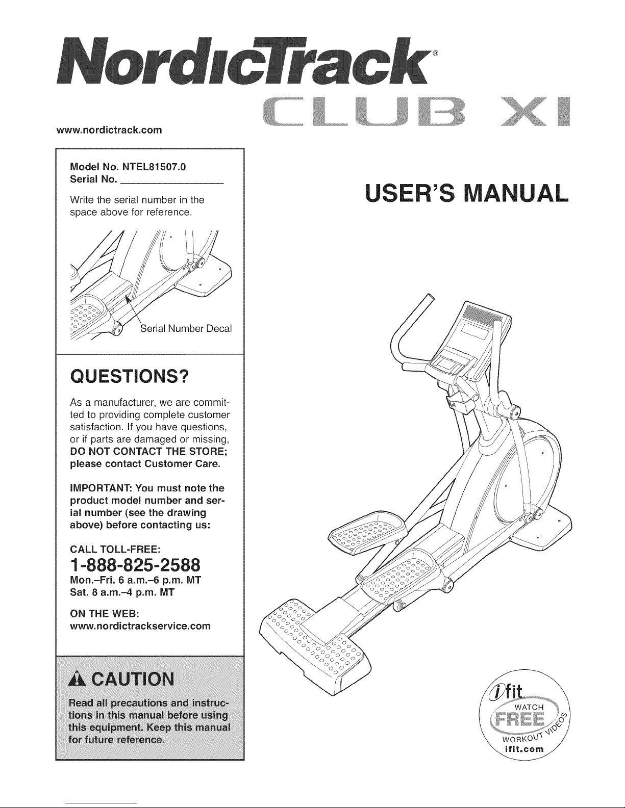
Model No. NTEL81507.0
Serial No.
Write the serial number in the
space above for reference.
Serial Number Decal
QUESTIONS?
As a manufacturer, we are commit-
ted to providing complete customer
satisfaction. If you have questions,
or if parts are damaged or missing,
DO NOT CONTACT THE STORE;
please contact Customer Care.
A UAL
IMPORTANT: You must note the
product model number and ser-
ial number (see the drawing
above) before contacting us:
CALL TOLL-FREE:
1-888-825-2588
Mon.-Fri. 6 a.m.-6 p.m. MT
Sat. 8 a.m.-4 p.m. MT
ON THE WEB:
www.nordictrackservice.com
Page 2

TABLE OF CONTENTS
WARNING DECAL PLACEMENT .............................................................. 2
IMPORTANT PRECAUTIONS ................................................................ 3
BEFORE YOU BEGIN ...................................................................... 4
ASSEMBLY ............................................................................... 5
HOW TO USE THE ELLIPTICAL EXERCISER .................................................. 10
MAINTENANCE AND TROUBLESHOOTING ................................................... 18
EXERCISE GUIDELINES ................................................................... 19
PART LIST .............................................................................. 20
EXPLODED DRAWING .................................................................... 21
ORDERING REPLACEMENT PARTS .................................................. Back Cover
LIMITED WARRANTY .............................................................. Back Cover
WARNING DECAL PLACEMENT
This drawing shows the location(s) of the
warning decal(s). If a decal is missing
or illegible, see the front cover of this
manual and request a free replace-
ment decal. Apply the decal in the
location shown. Note: The decal(s) may
not be shown at actual size.
may result in serious
injury.
• Read user's manual
prior to use and follow
all warnings and
instructions.
• Do not allow children
on oraroundmachine.
• Pedals continue to
spin when you stop
pedaling.
, Spinning pedals can
cause injury.
, Reduce pedal speed
in a controlledmanner.
• User weight must not
exceed 350 pounds.
, Replace label if
damaged, illegible, or
removed. [_
\
NordicTrack is a registered trademark of ICON IP, Inc.
2
Page 3
iMPORTANT PRECAUTIONS
A WARNING: Toreducethe.skofso.ous njury,reada.importantprecautionsand
instructions in this manual and all warnings on your elliptical exerciser before using your elliptical
exerciser, iCON assumes no responsibility for personal injury or property damage sustained by or
through the use of this product.
1. Before beginning any exercise program, 8.
consult your physician. This is especially
important for persons over age 35 or per-
sons with pre=existing health problems.
=
it is the responsibility of the owner to
ensure that all users of the elliptical exer-
ciser are adequately informed of all precau-
tions.
.
Keep the elliptical exerciser indoors, away
from moisture and dust. Do not place the
elliptical exerciser in a garage or covered
patio or near water.
,
Place the elliptical exerciser on a level sur-
face. To protect the floor or carpet from
damage, place a mat beneath the elliptical
exerciser. Make sure that there is at least 3
ft. (1 m) of clearance in the front and rear of
your elliptica! exerciser and 2 ft. (0.6 m) on
each side.
5_
inspect and properly tighten all parts regu-
larly. Replace any worn parts immediately.
Wear appropriate exercise clothes when
exercising; do not wear loose clothes that
could become caught on your elliptical exer-
ciser. Always wear athletic shoes for foot
protection.
9. Hold the handgrip pulse sensor or the han-
dlebars when mounting, dismounting, or
using your elliptical exerciser.
10. Keep your back straight while using your
elliptical exerciser; do not arch your back.
11.
The pulse sensor is not a medical device.
Various factors, including the user's move=
merit, may affect the accuracy of heart rate
readings. The pulse sensor is intended only
as an exercise aid in determining heart rate
trends in general.
12. When you stop exercising, allow the pedals
to slowly come to a stop.
13. if you feel pain or dizziness while exercis-
ing, stop immediately and cool down.
.
Keep children under age 12 and pets away
from your elliptical exerciser at all times.
=
Your elliptical exerciser should not be used
by persons weighing more than 350 Ibs.
(159 kg).
14. Use your elliptical exerciser only as
described in this manual.
3
Page 4
BEFORE YOU BEGIN
Thank you for selecting the revolutionary NordicTrack ®
CLUB XI elliptical exerciser. The CLUB XI elliptical
exerciser provides an impressive selection of features
designed to make your workouts at home more effec-
tive and enjoyable.
For your benefit, read this manual carefully before
you use the elliptical exerciser. If you have ques-
tions after reading this manual, please see the front
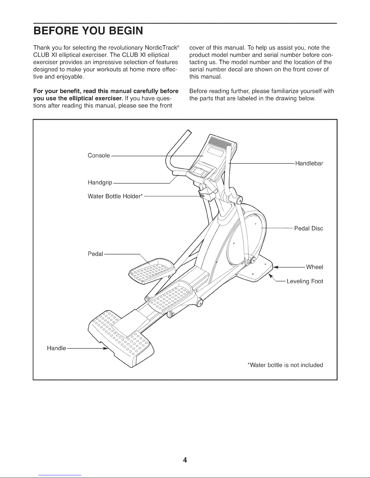
Console
Handgrip
Water Bottle Holder*
cover of this manual. To help us assist you, note the
product model number and serial number before con-
tacting us. The model number and the location of the
serial number decal are shown on the front cover of
this manual.
Before reading further, please familiarize yourself with
the parts that are labeled in the drawing below.
Handlebar
Handle
Pedal
Pedal Disc
\
Wheel
Leveling Foot
ooo o
*Water bottle is not included
4
Page 5
ASSEMBLY
Assembly requires two persons. Place all parts of the elliptical exerciser in a cleared area and remove the
packing materials. Do not dispose of the packing materials until assembly is completed.
in addition to the included tool(s), assembly requires a Phillips screwdriver _====_, an adjustable
wrench _, and a rubber mallet c_.
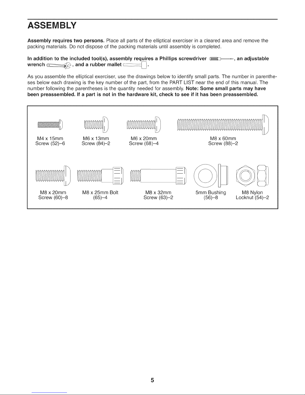
As you assemble the elliptical exerciser, use the drawings below to identify small parts. The number in parenthe-
ses below each drawing is the key number of the part, from the PART LIST near the end of this manual. The
number following the parentheses is the quantity needed for assembly. Note: Some small parts may have
been preassembled. If a part is not in the hardware kit, check to see if it has been preassembled.
M4x 15mm M6 x 13mm
Screw (52)-6 Screw (84)-2
M8 x 20mm M8 x 25mm Bolt M8 x 32mm
Screw (60)-8 (65)-4 Screw (63)-2
M6 x 20mm M8 x 60mm
Screw (68)-4 Screw (88)-2
5mm Bushing
(56)-8
M8 Nylon
Locknut (54)-2
5
Page 6
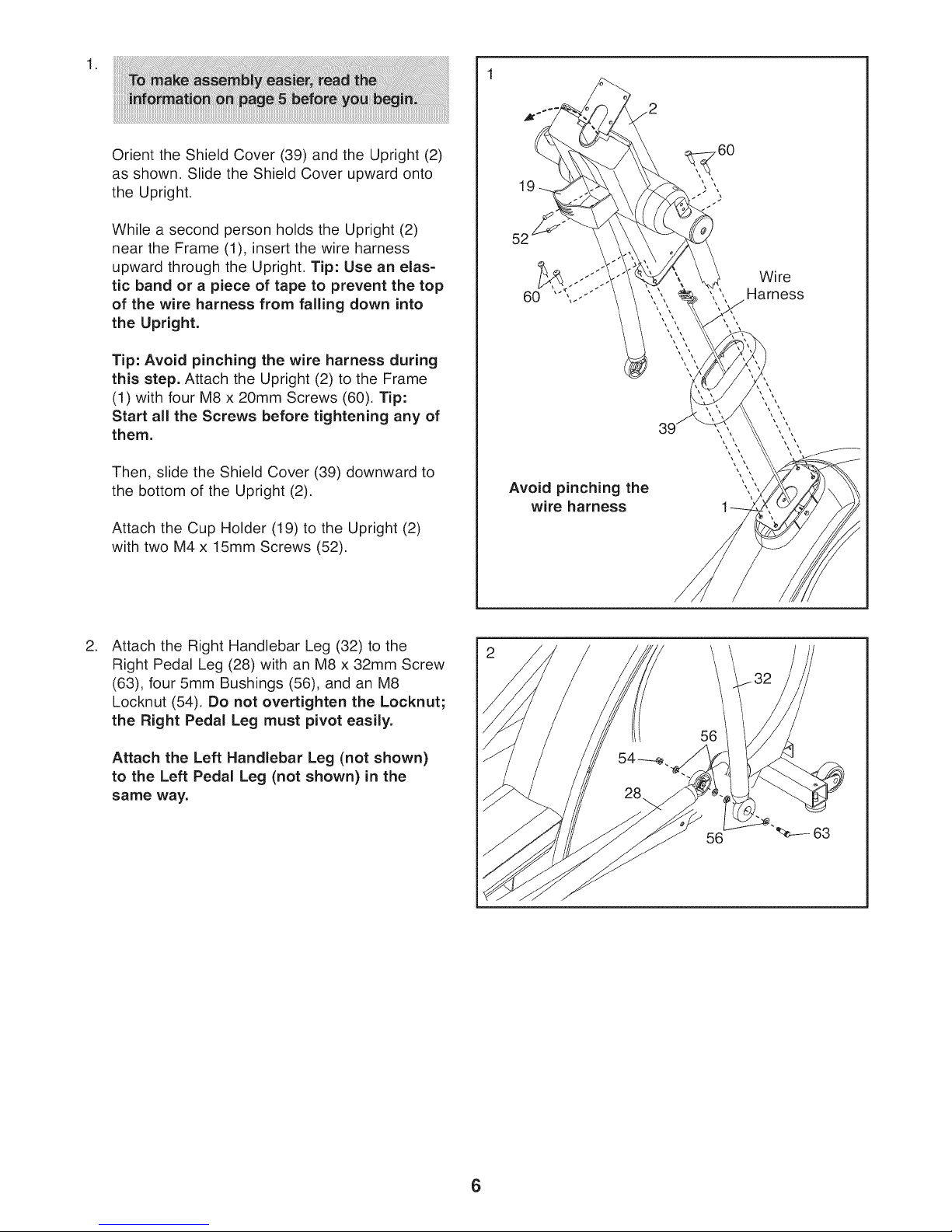
Orient the Shield Cover (39) and the Upright (2)
as shown. Slide the Shield Cover upward onto
the Upright.
19
,60
\\\
While a second person holds the Upright (2)
near the Frame (1), insert the wire harness
upward through the Upright. Tip: Use an elas-
tic band or a piece of tape to prevent the top
of the wire harness from falling down into
the Upright.
Tip: Avoid pinching the wire harness during
this step. Attach the Upright (2) to the Frame
(1) with four M8 x 20mm Screws (60), Tip:
Start all the Screws before tightening any of
them.
Then, slide the Shield Cover (39) downward to
the bottom of the Upright (2).
Attach the Cup Holder (19) to the Upright (2)
with two M4 x 15mm Screws (52).
.
Attach the Right Handlebar Leg (32) to the
Right Pedal Leg (28) with an M8 x 32mm Screw
(63), four 5mm Bushings (56), and an M8
Locknut (54), Do not overtighten the Locknut;
the Right Pedal Leg must pivot easily.
52
60
Avoid pinching the
wire harness
Wire
Harness
\\
\\
Attach the Left Handlebar Leg (not shown)
to the Left Pedal Leg (not shown) in the
same way.
56
63
6
Page 7
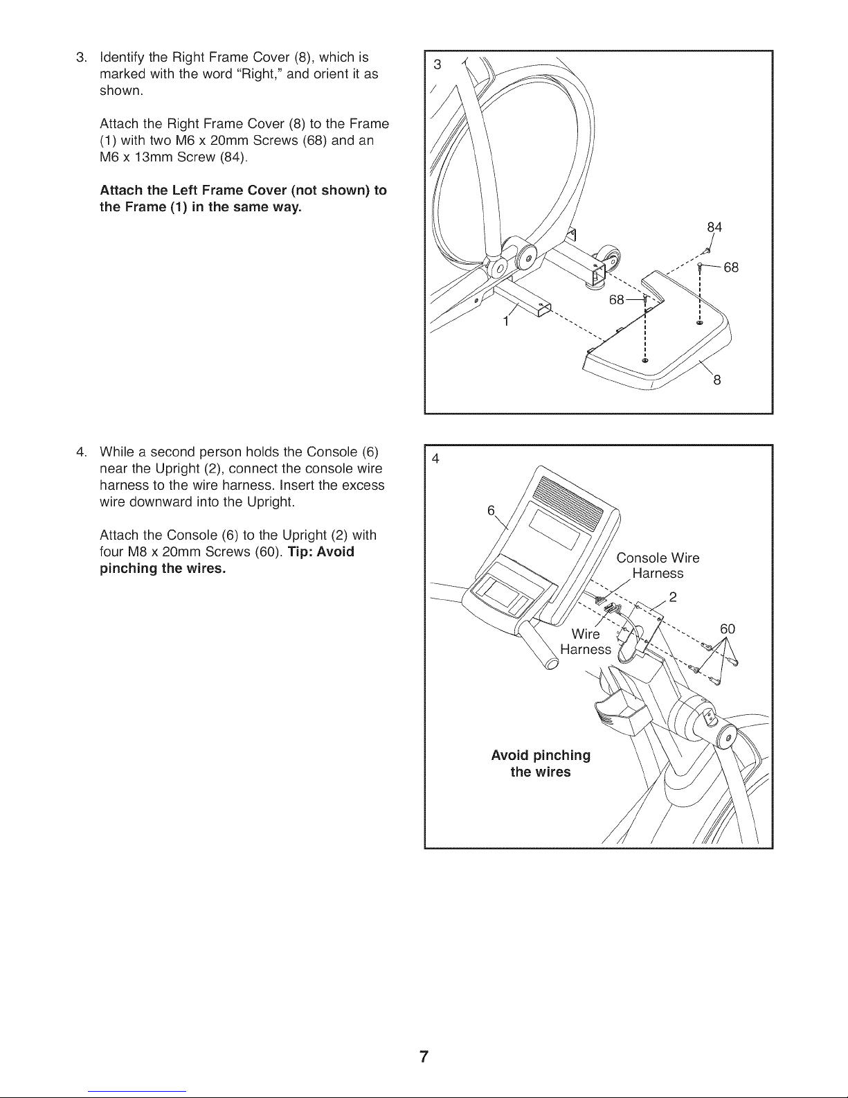
.
Identify the Right Frame Cover (8), which is
marked with the word g , and orient it as
"Ri ht"
shown.
Attach the Right Frame Cover (8) to the Frame
(1) with two M6 x 20mm Screws (68) and an
M6 x 13mm Screw (84).
Attach the Left Frame Cover (not shown) to
the Frame (1) in the same way.
.
While a second person holds the Console (6)
near the Upright (2), connect the console wire
harness to the wire harness. Insert the excess
wire downward into the Upright.
Attach the Console (6) to the Upright (2) with
four M8 x 20mm Screws (60). Tip: Avoid
pinching the wires.
Console Wire
Harness
60
Avoid pinching
the wires
7
Page 8

Identify the Right Handlebar (35), which is
5. 5
marked with an "R" sticker. Apply a generous
amount of the included fastener adhesive to two
M8 x 25mm Bolts (65). Then, attach the Right
Handlebar to the Right Handlebar Leg (32) with
the two Bolts.
Attach the Left Handlebar (not shown) to the
Left Handlebar Leg (not shown) in the same
way.
65
.
Attach the Rear Stabilizer Cover (5) to the
Stabilizer Bracket (86) with two M8 x 60mm
Screws (88). Next, attach the Stabilizer Block
(90) to the Stabilizer Bracket with two M4 x
15mm Screws (52).
6
8
Page 9

Remove the adhesive backing from the Rear
7. 7
Stabilizer Overlay (10) and from the Rear
Stabilizer Cover (5). Press the Rear Stabilizer
Overlay onto the Track Frame (3) and the Rear
Stabilizer Cover.
10
8. Make sure that all parts of the elliptical exerciser are properly tightened. Note: Some hardware may be
left over after assembly is completed. To protect the floor or carpet from damage, place a mat under the
elliptical exerciser.
9
Page 10

HOW TO USE THE ELLiPTiCAL EXERCISER
HOW TO MOVE THE ELLiPTiCAL EXERCISER
Due to the size and weight of the elliptical exer-
ciser, moving it requires two persons. Have two
persons lift the indicated end of the elliptical exerciser
until the elliptical exerciser will roll on the front wheels.
Carefully move the elliptical exerciser to the desired
location and then lower it to the level position. CAU-
TION: To decrease the risk of injury, bend your
legs and keep your back straight. Make sure to
use your legs rather than your back to lift the ellip-
tical exerciser. Do not attempt to move the ellipti-
cal exerciser over an uneven surface.
HOW TO EXERCISE ON THE ELLIPTICAL
EXERCISER
To mount the elliptical exerciser, hold the handlebars
and step onto the pedal that is in the lowest position.
Then, step onto the other pedal. Push the pedals until
they begin to move with a continuous motion. Note:
The pedal discs can turn in either direction. It is
recommended that you turn the pedal discs in the
direction shown by the arrow; however, for variety,
you can turn the pedal discs in the opposite direc-
tion.
Wheel
Leveling
Feet
Lift here
HOW TO LEVEL THE ELLIPTICAL EXERCISER
If the elliptical exerciser rocks slightly on your floor
during use, turn one or both of the leveling feet
beneath the front stabilizer until the rocking motion is
eliminated. Then, turn the leveling foot beneath the
center of the frame to prevent the frame from flexing.
Pedal
Disc
To dismount the elliptical exerciser, wait until the ped-
als come to a complete stop. Note: The elliptical
exerciser does not have a freewheel; the pedals
will continue to move until the flywheel stops.
When the pedals are stationary, step off the higher
pedal first. Then, step off the lower pedal.
10
Page 11

DISTRMCE
v II..... 1
QUICKTOUCH PROGRAMS
...... IEW(_L_ ..............
QUICKTOUOH RESISTANCE
2 4 6 8 10 12 14 16 /
START
PAUSE
jjJ-
,r/j
FEATURES OF THE CONSOLE
The advanced console offers an array of features
designed to make your workouts more effective and
enjoyable.
When you use the quick start mode of the console,
you can change the resistance of the pedals with the
touch of a button. As you exercise, the console will
provide continuous exercise feedback, You can even
measure your heart rate using the optional chest pulse
sensor. Note: For information about the optional
chest pulse sensor, see page 18.
The console offers nineteen preset programs, Each
program automatically changes the resistance of the
pedals and prompts you to maintain a target pace as it
guides you through an effective workout.
J
J
RES2NOE
1l.......................
The console also offers three manual programs that
allow you to set your own time, distance, or calorie
goal for the workout.
The console features the iFit Interactive Workout
System, which enables the console to accept iFit
cards containing workouts designed to help you
achieve specific fitness goals, iFit cards are available
separately, To purchase iFit cards, go to
www.iFit.com or see the front cover of this man-
ual. iFit cards are also available at select stores.
To use the quick start mode, see page 12, To use a
MANUAL program, see page 13, To use a preset
program, see page 15. To use the COOL DOWN
mode, see page 16 To use the maintenance mode,
see page 17. To use an iFit workout, see page 18.
11
Page 12

HOW TO ACTIVATE THE CONSOLE 4. Follow your progress with the displays.
The elliptical exerciser requires no batteries or
external power source. Power is supplied by a gen-
erator as you pedal. To turn on the console, begin
pedaling at a speed of about 25 revolutions per minute
or faster. After a few seconds, the console display will
light and the console will be ready for use.
iMPORTANT: If the elliptical exerciser has been
exposed to cold temperatures, allow it to warm to
room temperature before turning on the console. If
you do not do this, the console displays or other
electronic components may become damaged.
HOW TO USE THE QUICK START MODE
If you do not plan to use a program, the quick start
mode will allow you to simply start exercising and
adjust the resistance of the pedals manually.
1. Begin pedaling to activate the console.
When you activate the console, the display will
light and the console will be ready for use.
2. Select the quick start mode.
When you activate the console, the quick start
mode will be selected. If you have selected a pro-
gram, reselect the quick start mode by pressing
any of the QUICKTOUCH PROGRAMS buttons
repeatedly until zeros appear in the display.
The display will show the elapsed time and the
distance you have pedaled. Note: When a preset
program or the MANUAL TIME program is
selected, the display will show the time remaining
in the program instead of the elapsed time.
The display will also show your heart rate (in beats
per minute) when you use the optional chest pulse
sensor (see page 18).
TIME DISTAHCE
You can also view selected information at a larger
size. Press the DISPLAY button repeatedly to view
the elapsed time, the distance that you have ped-
aled, or the approximate number of calories that
you have burned.
To view the elapsed time, your exercise intensity in
mets, the approximate number of calories you
have burned, the distance, the resistance level,
the approximate number of calories you are burn-
ing per hour, and your pedaling pace in one dis-
play, press the DISPLAY button again.
TIME DISTFIHCE
.
Press the START button to start the quick start
mode and change the resistance of the pedals
as desired.
As you pedal, change the resistance of the pedals
by pressing the RESISTANCE increase and
decrease buttons or the numbered QUICKTOUCH
RESISTANCE buttons. There are sixteen resis-
tance levels. Note: After you press a RESIS-
TANCE button, it will take a moment for the pedals
to reach the selected resistance level.
To view the elapsed time, the distance you have
pedaled, and the approximate number of calories
you have burned in one display, press the DIS-
PLAY button again.
To again view the elapsed time and the distance
that you have pedaled, press the DISPLAY button
again.
Press the PAUSE button to pause the quick start
mode at any time. Simply resume pedaling or
press the START button to restart the quick start
mode.
Note: The display may be able to display text mes-
sages in any of six languages (see step 5 on page
17).
.
When you are finished using the elliptical exer-
ciser, the console will turn off automatically.
If the pedals do not move for several minutes, the
displays will be reset and the console will turn off
automatically.
12
Page 13

HOW TO USE A MANUAL PROGRAM 4. Enter your weight.
A MANUAL program allows you to set a time, dis-
tance, or calorie goal for your workout as you control
the resistance of the pedals.
1. Begin pedaling to activate the console.
When you activate the console, the display will
light and the console will be ready for use.
2. Select a MANUAL program.
To select one of the three MANUAL programs, first
press the MANUAL button repeatedly until the
words MANUAL TIME, MANUAL DISTANCE, or
MANUAL CALORIES appear in the display. A pro-
file of the resistance settings of the program and
the program goal will also appear in the display.
Then, press the ENTER button to confirm your
selection.
Profile
Next, the words "ENTER WEIGHT" and a weight
setting of 185 pounds (US) will appear in the main
display. To enter your weight (1 kilogram = 2.2
pounds), press the increase and decrease buttons
beside the ENTER button. Then, press the ENTER
button.
18_ POUNDS
UP, BDWH RRRn_ Tn HnJUST, EHTER Tn REEEPT
5. Enter a goal for the program.
If you selected the MANUAL TIME program, the
words "ENTER WORKOUT TIME" and a time set-
ting of 30 minutes will appear in the display. To
change the length of time that the program will
last, press the increase and decrease buttons
beside the ENTER button.
PRrIr.RRF'I TIHE
3n:Drl
3. Enter your age.
A moment after you select a MANUAL program,
the words "ENTER AGE" and an age setting of 35
will flash in the display. To enter your age, press
the increase and decrease buttons beside the
ENTER button. Then, press the ENTER button.
35 YEARS
liP, DDWH BRRDW TQ Rr_JuS"f, EHTEB TD Rr'EEPT
If you selected the MANUAL DISTANCE pro-
gram, the words "ENTER WORKOUT DISTANCE"
and a distance setting will appear in the display. To
change the distance goal for the program, press
the increase and decrease buttons beside the
ENTER button.
If you selected the MANUAL CALORIES pro-
gram, the words "ENTER WORKOUT CALORIES"
and a calorie setting of 300 calories will appear in
the display, To change the calorie goal for the pro-
gram, press the increase and decrease buttons
beside the ENTER button.
13
Page 14

.
Press the START button or begin pedaling to
start the program.
Each program is divided into several one-minute
segments. During the program, the program profile
will show your progress (see the drawing in step 2
on page 13). The flashing segment of the profile
represents the current segment of the program.
The height of the flashing segment indicates the
resistance level for the current segment. At the
end of each segment of the program, a series of
tones will sound and the next segment of the pro-
file will begin to flash.
As you pedal, change the resistance of the pedals
as desired by pressing the RESISTANCE increase
and decrease buttons or the numbered QUICK-
TOUCH RESISTANCE buttons. There are sixteen
resistance levels. Note: After you press a RESIS-
TANCE button, it will take a moment for the pedals
to reach the selected resistance level. The default
resistance level for the MANUAL programs is
resistance level 3.
The program will continue in this way until the last
segment of the profile flashes. To stop the pro-
gram at any time, stop pedaling or press the
PAUSE button. To restart the program, simply
resume pedaling or press the START button. To
exit the program at any time, press the CLEAR
button.
If you selected the MANUAL TiME program, the
display will count down the time remaining in the
program. If you selected the MANUAL DiS-
TANCE program, the display will count down the
distance, if you selected the MANUAL CALO-
RIES program, the display will count down the
approximate number of calories you are burning.
To view the time, your exercise intensity in mets,
and your power output in watts, press the DIS-
PLAY button.
To view the time, the approximate number of calo-
ries you have burned, and the distance you have
pedaled, press the DISPLAY button again.
To again view the time, your exercise intensity in
mets, the approximate number of calories you
have burned, the approximate number of calories
you are burning per hour, and the distance you
have pedaled, press the DISPLAY button again.
.
When you are finished using the elliptical
trainer, the console will turn off automatically.
If the pedals do not move for several minutes, the
displays will be reset and the console will turn off
automatically.
7. Follow your progress with the displays.
During a MANUAL program, the display will show
the time, the distance you have pedaled, the
approximate number of calories you have burned,
your exercise intensity in mets, your pedaling
pace, and the resistance level. The display will
also show your heart rate when you use the
optional chest pulse sensor (see page 18).
14
Page 15

HOW TO USE A PRESET PROGRAM 4. Enter your weight.
A preset program will automatically change the resis-
tance of the pedals and prompt you to maintain a tar-
get pace while guiding you through your workout.
1. Begin pedaling to activate the console.
When you activate the console, the display will
light and the console will be ready for use.
2. Select a preset program.
To select one of the nineteen preset programs,
first press the PLATEAU, FOOTHILLS, ALL TER-
RAIN, INTERVAL, or RANDOM button repeatedly
until the name of the desired preset program
appears in the display. A profile of the resistance
settings of the program, the maximum resistance
level, the program time, and the maximum rpm
setting for the program will also appear in the dis-
play. Then, press the ENTER button to confirm
your selection.
Profile
Next, the words "ENTER WEIGHT" and a weight
setting of 185 pounds (US) will appear in the main
display. To enter your weight (1 kilogram = 2.2
pounds), press the increase and decrease buttons
beside the ENTER button. Then, press the ENTER
button.
18_ POUNDS
UP, BBWH RRRBW TB ABJBST, EHTER TB RECEPT
.
Press the START button or begin pedaling to
start the program.
Each preset program is divided into 20 or 30 one-
minute segments. One resistance level and one
target rpm (pace) setting is programmed for each
segment. Note: The same resistance setting
and/or target rpm may be programmed for consec-
utive segments.
3. Enter your age.
A moment after you select a preset program, the
words "ENTER AGE" and an age setting of 35 will
flash in the display. To enter your age, press the
increase and decrease buttons beside the ENTER
button. Then, press the ENTER button.
35 YERRS
LIP, r_DWH FIRRD_ TB R_JUST, EHTER TD REr'EpT
During the program, the program profile will show
your progress (see the drawing to the left). The
flashing column of the profile represents the cur-
rent segment of the program. The height of the
flashing column indicates the resistance level for
the current segment. At the end of each segment
of the program, a series of tones will sound and
the next segment of the profile will begin to flash.
If a different resistance level is programmed for
the next segment, the resistance level will appear
in the display for a few seconds to alert you. The
resistance of the pedals will then change.
As you exercise, keep
your pedaling pace
near the target rpm
setting for the current
segment, which is
shown in the display.
IMPORTANT: The target rpm settings are
intended only to provide motivation. Your
actual pace may be slower than the target rpm
settings. Make sure to pedal at a pace that is
comfortable for you.
15
Page 16

If the resistance level for the current segment is
too high or too low, you can manually override the
setting by pressing the RESISTANCE buttons.
However, when the current segment ends, the ped-
als will automatically adjust to the resistance level
for the next segment.
The program will continue in this way until the last
segment of the profile flashes. To stop the pro-
gram at any time, stop pedaling or press the
PAUSE button. To resume the program, simply
resume pedaling or press the START button. To
exit the program at any time, press the CLEAR
button
6. Follow your progress with the displays.
During a preset program, the display will show the
elapsed time, your exercise intensity in mets, the
approximate number of calories you have burned,
the approximate number of calories you are burn-
ing per hour, and the distance you have pedaled.
The display will also show your heart rate when
you use the optional chest pulse sensor (see page
18).
To view the time, your exercise intensity in mets,
and your power output in watts, press the DIS-
PLAY button.
To view the time, the approximate number of calo-
ries you have burned, and the distance you have
pedaled, press the DISPLAY button again.
To again view the time, your exercise intensity in
mets, the approximate number of calories you
have burned, the approximate number of calories
you are burning per hour, and the distance you
have pedaled, press the DISPLAY button again.
.
When you are finished using the elliptical
trainer, the console will turn off automatically.
If the pedals do not move for several minutes, the
displays will be reset and the console will turn off
automatically.
HOW TO USE THE COOL DOWN MODE
The COOL DOWN mode is designed to help you cool
down after you have finished exercising. Press the
COOL DOWN button to use the COOL DOWN mode.
The COOL DOWN mode is divided into three one-
minute segments. The cool down mode will work in
the same way as a preset program (see step 5 on
page 15).
16
Page 17

HOW TO USE THE MAINTENANCE MODE
The console features a maintenance mode that allows
you to access usage information and to view and
change default settings.
1. Press any button or begin pedaling to activate
the console.
When you activate the console, the display will
light and the console will be ready for use.
2. Hold down the CLEAR button and the ENTER
button simultaneously for a few seconds to
select the maintenance mode.
When the maintenance mode is selected, the
words "MAINTENANCE MODE SCREEN 1" will
appear in the display.
Note: As you view the maintenance mode screens,
press the BACK button at any time to return to the
previous screen.
3. View usage information for the elliptical
exerciser.
.
Press the DISPLAY button and change the time
settings if desired.
When the words "MAINTENANCE MODE
SCREEN 2" appear, the display will allow you to
set a maximum program time for the programs
and a default time for the pause timeout.
The maximum program time for the programs can
be from 10 minutes to 90 minutes. To change the
maximum program time, press the increase and
decrease buttons beside the ENTER button. Then,
press the DISPLAY button.
If the pedals on the elliptical exerciser do not
move for a period of time, a pause timeout will
occur and the console will enter an idle mode.
When the console is in the idle mode, the displays
will be reset to zeros and a screen saver will
appear in the display.
The pause timeout can occur from 1 minute to 5
minutes after the pedals stop moving. To change
the length of time that will elapse before the pause
timeout, press the increase and decrease buttons
beside the ENTER button.
When the words "MAINTENANCE MODE
SCREEN 1" appear, the display will show the total
number of hours that the elliptical exerciser has
been used and the total distance that the elliptical
exerciser has been pedaled.
n m
TnTF]L HDLIRS: Z.l.q
TnTF]L MILES: EE.nD
.
Press the DISPLAY button again and select a
language for the display.
The display may be able to display text messages
in English, International English, German,
Spanish, Italian, or French. To change the lan-
guage, press the increase and decrease buttons
beside the ENTER button.
.
Press the DISPLAY button to exit the mainte-
nance mode.
17
Page 18

HOW TO USE AN IFIT WORKOUT
iFit cards are available separately. To purchase iFit
cards, go to www.iFit.com or see the front cover of this
manual, iFit cards are also available at select stores.
1. Press any button or begin pedaling to activate
the console.
3. When you are finished exercising, remove the
iFit card.
Remove the iFit card when you are finished exer-
cising. Store the iFit card in a secure place.
THE OPTIONAL CHEST PULSE SENSOR
When you activate the console, the display will
light and the console will be ready for use.
2. Insert an iFit card and select a workout.
To use an iFit workout, insert an iFit card into the
iFit slot, which is located on the rear right-hand
side of the console. The iFit card should slide eas-
ily into the slot. If it does not, turn the iFit card and
try again.
iFit workouts function in the same way as preset
workouts. To use the workout, see steps 5 to 7 on
pages 15 to 16. Note: Some iFit cards contain
more than one workout. To select a workout, use
the increase and decrease buttons located next to
the ENTER button.
The optional chest pulse sensor provides hands-free
operation and continuously monitors your heart rate
during your workouts. To purchase the optional
chest pulse sensor, see the front cover of this
manual.
MAINTENANCE AND TROUBLESHOOTING
if you have questions about maintenance or trou-
bleshooting, see the front cover of this manual.
Inspect and tighten all parts of the elliptical exerciser
regularly. Replace any worn parts immediately.
To clean the elliptical exerciser, use a damp cloth and
a small amount of mild soap. Make sure to regularly
clean the track wheels and the track frame on which
the track wheels ride. IMPORTANT: To avoid damage
to the console, keep liquids away from the con-
sole and keep the console out of direct sunlight.
HOW TO LEVEL THE ELLIPTICAL EXERCISER
If the elliptical exerciser rocks slightly on your floor
during use, see HOW TO LEVEL THE ELLIPTICAL
EXERCISER on page 10.
18
Page 19

EXERCISE GUiDELiNES
These guidelines will help you to plan your exercise
program. For detailed exercise information, obtain a
reputable book or consult your physician. Remember,
proper nutrition and adequate rest are essential for
successful results.
Burning Fat--To burn fat effectively, you must exer-
cise at a low intensity level for a sustained period of
time, During the first few minutes of exercise, your
body uses carbohydrate calories for energy. Only after
the first few minutes of exercise does your body begin
to use stored fat calories for energy, If your goal is to
burn fat, adjust the intensity of your exercise until your
heart rate is near the lowest number in your training
zone, For maximum fat burning, exercise with your
heart rate near the middle number in your training
zone.
Aerobic Exercise--If your goal is to strengthen your
cardiovascular system, you must perform aerobic
exercise, which is activity that requires large amounts
of oxygen for prolonged periods of time, For aerobic
exercise, adjust the intensity of your exercise until
your heart rate is near the highest number in your
training zone.
EXERCISE INTENSITY
Whether your goal is to burn fat or to strengthen your
cardiovascular system, exercising at the proper inten-
sity is the key to achieving results. You can use your
heart rate as a guide to find the proper intensity level.
The chart below shows recommended heart rates for
fat burning and aerobic exercise.
165 155 145 140 130 125 115 _V_
145 I38 130 125 118 110 103 _V_
125 I20 ]15 110 105 95 90 U
20 30 40 50 60 70 80
To find the proper intensity level, find your age at the
bottom of the chart (ages are rounded off to the near-
est ten years). The three numbers listed above your
age define your "training zone." The lowest number is
the heart rate for fat burning, the middle number is the
heart rate for maximum fat burning, and the highest
number is the heart rate for aerobic exercise.
WORKOUT GUIDELINES
Warming Up--Start with 5 to 10 minutes of stretching
and light exercise, A warm-up increases your body
temperature, heart rate, and circulation in preparation
for exercise.
Training Zone Exercise--Exercise for 20 to 30 min-
utes with your heart rate in your training zone. (During
the first few weeks of your exercise program, do not
keep your heart rate in your training zone for longer
than 20 minutes.) Breathe regularly and deeply as you
exercise-never hold your breath.
Cooling Down--Finish with 5 to 10 minutes of
stretching. Stretching increases the flexibility of your
muscles and helps to prevent post-exercise problems.
EXERCISE FREQUENCY
To maintain or improve your condition, complete three
workouts each week, with at least one day of rest
between workouts. After a few months of regular exer-
cise, you may complete up to five workouts each
week, if desired. Remember, the key to success is to
make exercise a regular and enjoyable part of your
everyday life.
19
Page 20

PART LIST=lVlodel No. NTEL81507.0 R0109A
Key No. Qty. Description Key No. Qty. Description
1 1 Frame 52 6 M4 x 15mm Screw
2 1 Upright 53 1 Console Back Cover
3 1 Track Frame 54 10 M8 Locknut
4 1 Rear Stabilizer 55 2 Track Cap
5 1 Rear Stabilizer Cover 56 8 5mm Bushing
6 1 Console 57 1 M4 Washer
7 1 Left Frame Cover 58 10 M4 x 50mm Screw
8 1 Right Frame Cover 59 2 M12 x 60mm Bolt
9 2 Crank Arm 60 8 M8 x 20mm Screw
10 1 Rear Stabilizer Overlay 61 2 M6 Large Washer
11 1 Upright Cover 62 6 M8 x 42mm Bolt
12 1 Generator 63 2 M8 x 32mm Screw
13 1 Pulley 64 6 M10 x 20mm Screw
14 1 Handlebar Axle 65 4 M8 x 25mm Bolt
15 1 Pulley Axle 66 2 M6 x 20mm Screw
16 1 Axle Plate 67 17 M4 x 10mm Screw
17 1 Left Handlebar Cover 68 23 M6 x 20mm Screw
18 1 Right Handlebar Cover 69 3 M6 x 140mm Screw
19 1 Cup Holder 70 6 M6 x 100mm Screw
20 1 Power Board 71 2 M6 x 40mm Screw
21 1 Power Board Bracket 72 2 M6 x 25mm Screw
22 1 Frame Cover Bracket 73 2 M12 Locknut
23 1 Battery Pack 74 1 Console Handlebar
24 1 Drive Belt 75 1 Console Back
25 2 Transport Wheel 76 2 Key
26 2 Track Arm 77 4 M5 x 15mm Screw
27 1 Left Pedal Leg 78 2 M4 x 14mm Screw
28 1 Right Pedal Leg 79 2 M6 x 60mm Screw
29 1 Left Handlebar Leg 80 2 Track Wheel
30 1 Left Pedal 81 8 M6 x 30mm Hex Bolt
31 1 Right Pedal 82 2 M8 x 80mm Bolt
32 1 Right Handlebar Leg 83 24 M3 x 6mm Screw
33 2 Handlebar Foam 84 4 M6 x 13mm Screw
34 1 Left Handlebar 85 2 M4 x 14mm Screw
35 1 Right Handlebar 86 1 Stabilizer Bracket
36 1 Right Shield 87 12 M3 Stand-off
37 1 Left Shield 88 2 M8 x 60mm Screw
38 2 Pedal Disc 89 2 Hand Grip
39 1 Shield Cover 90 1 Stabilizer Block
40 2 Rear Stabilizer Foot 91 8 M6 Split Washer
41 3 Frame Foot 92 8 M6 Washer
42 10 25mm Bearing 93 12 M5 Washer
43 8 Wave Washer 94 12 M4 Split Washer
44 8 Bushing * - User's Manual
45 2 14mm Spacer * - Fastener Adhesive Packet
46 1 Large Washer * - 40" Console Wire
47 6 11mm Round Cap * - 7" ECA Jumper Wire
48 4 Wheel Bushing * - 6" CN-3 Jumper Wire
49 2 Handlebar Cap * - 10" Ground Wire
50 10 Snap Ring * - CN-2 Generator Wire
51 1 Small Control Board * - CN-1 Generator Wire
Note: Specifications are subject to change without notice. See the back cover of this manual for information about
ordering replacement parts. *These parts are not illustrated.
2O
Page 21

EXPLODED DRAWING AmlVlodel No. NTEL81507.0 RologA
74
44
82
62
20
85
,58
46
73
58
58
25
81
77
91
81
84
21
Page 22

EXPLODED DRAWING B--IVlodel No. NTEL81507.0 RologA
66
33
34
65
56
26
65
44
44
43
_0 47
64 47
L_044
64
43
56/_
54
56 63
\
44
67 67
55
48
80 48
8O
55
22
42
26
oO_O°O '
o°o°o
43
31
54
56
o°o °
s
56
28
42
50 47
64
43
Page 23

EXPLODED DRAWING CmlVlodel No. NTEL81507.0 RologA
7O
71
39
38
68
68
36
71
68
^ _79
7O
7
84
84
23
Page 24

ORDERING REPLACEMENT PARTS
To order replacement parts, please see the front cover of this manual. To help us assist you, be prepared to
provide the following information when contacting us:
- the model number and serial number of the product (see the front cover of this manual)
- the name of the product (see the front cover of this manual)
- the key number and description of the replacement part(s) (see the PART LIST and the EXPLODED
DRAWING near the end of this manual)
LIMITED WARRANTY
ICON Health & Fitness, Inc. (ICON) warrants this product to be free from defects in workmanship and
material, under normal use and service conditions. The frame is warranted for a lifetime. Parts are war-
ranted for three (3) years from the date of purchase. Labor is warranted for two (2) years from the date
of purchase.
This warranty extends only to the original purchaser. ICON's obligation under this warranty is limited to
repairing or replacing, at ICON's option, the product through one of its authorized service centers. All
repairs for which warranty claims are made must be preauthorized by ICON. If the product is shipped to
a service center, freight charges to and from the service center will be the customer's responsibility. For
replacement parts shipped while the product is under warranty, the customer will be responsible for a
minimal handling charge. For in-home service, the customer will be responsible for a minimal trip
charge. This warranty does not extend to any damage to a product caused by or attributable to freight
damage, abuse, misuse, improper or abnormal usage, or repairs not provided by an ICON authorized
service center; products used for commercial or rental purposes; or products used as store display
models. No other warranty beyond that specifically set forth above is authorized by ICON.
ICON is not responsible or liable for indirect, special, or consequential damages arising out of or in con-
nection with the use or performance of the product; damages with respect to any economic loss, loss of
property, loss of revenues or profits, loss of enjoyment or use, or costs of removal or installation; or
other consequential damages of whatsoever nature. Some states do not allow the exclusion or limita-
tion of incidental or consequential damages. Accordingly, the above limitation may not apply to you.
The warranty extended hereunder is in lieu of any and all other warranties, and any implied warranties
of merchantability or fitness for a particular purpose are limited in their scope and duration to the terms
set forth herein. Some states do not allow limitations on how long an implied warranty lasts.
Accordingly, the above limitation may not apply to you.
This warranty gives you specific legal rights. You may also have other rights that vary from state to state.
iCON Health & Fitness, inc., 1500 S. 1000 W., Logan, UT 84321-9813
Part No. 277976 R0109A Printed in USA © 2009 ICON IP, Inc.
 Loading...