

Page 1

PAMS Technical Documentation
NSE 8/9 Series Transceivers
Service Software
Instructions
Issue 1 07/99
Page 2

NSE 8/9
PAMS
Service Software Instructions
Technical Documentation
CONTENTS
Installing the Software 5. . . . . . . . . . . . . . . . . . . . . . . . . . . . . . . . . . . . . . . . . . . .
Hardware requirements for Windows 3.1x 5. . . . . . . . . . . . . . . . . . . . . . . .
Hardware requirements for Windows 95 5. . . . . . . . . . . . . . . . . . . . . . . . . .
Software Environment of the Support Modules 5. . . . . . . . . . . . . . . . . . . .
Required Servicing Equipment 6. . . . . . . . . . . . . . . . . . . . . . . . . . . . . . . . . . . . .
Equipment Setup 7. . . . . . . . . . . . . . . . . . . . . . . . . . . . . . . . . . . . . . . . . . . . . .
Installing the Software on PC Hard Disk 8. . . . . . . . . . . . . . . . . . . . . . . . . .
Using the Software with a Hard Drive 8. . . . . . . . . . . . . . . . . . . . . . . . .
Equipment Setup for Tuning a Phone without Removing Covers 9. . . . .
Flash Concept for NSE–8/9 (covers on) 10. . . . . . . . . . . . . . . . . . . . . . . . . .
Flash Concept for NSE–8/9 (covers off) 11. . . . . . . . . . . . . . . . . . . . . . . . . .
Tuning With Covers Off 12. . . . . . . . . . . . . . . . . . . . . . . . . . . . . . . . . . . . . . . .
Warranty Transfer 13. . . . . . . . . . . . . . . . . . . . . . . . . . . . . . . . . . . . . . . . . . . . .
Tuning Steps 14. . . . . . . . . . . . . . . . . . . . . . . . . . . . . . . . . . . . . . . . . . . . . . . . . . . .
1. RX Calibration (AGC + AFC) 14. . . . . . . . . . . . . . . . . . . . . . . . . . . . . . . . .
2. Alignment of Transmitter Power Levels 15. . . . . . . . . . . . . . . . . . . . . . . .
3. I/Q Modulator Alignments 17. . . . . . . . . . . . . . . . . . . . . . . . . . . . . . . . . . . .
4. Energy Management Calibration 19. . . . . . . . . . . . . . . . . . . . . . . . . . . . . .
Common User Interface 20. . . . . . . . . . . . . . . . . . . . . . . . . . . . . . . . . . . . . . . . . . .
NSE–8 Features 21. . . . . . . . . . . . . . . . . . . . . . . . . . . . . . . . . . . . . . . . . . . . . . . . .
Product 21. . . . . . . . . . . . . . . . . . . . . . . . . . . . . . . . . . . . . . . . . . . . . . . . . . . . . .
New command 21. . . . . . . . . . . . . . . . . . . . . . . . . . . . . . . . . . . . . . . . . . . . .
Open... command 21. . . . . . . . . . . . . . . . . . . . . . . . . . . . . . . . . . . . . . . . . .
Initialise... command 21. . . . . . . . . . . . . . . . . . . . . . . . . . . . . . . . . . . . . . . .
Normal Mode 21. . . . . . . . . . . . . . . . . . . . . . . . . . . . . . . . . . . . . . . . . . . . . .
Local Mode 22. . . . . . . . . . . . . . . . . . . . . . . . . . . . . . . . . . . . . . . . . . . . . . . .
Band command 22. . . . . . . . . . . . . . . . . . . . . . . . . . . . . . . . . . . . . . . . . . . .
GSM 22. . . . . . . . . . . . . . . . . . . . . . . . . . . . . . . . . . . . . . . . . . . . . . . . . . . . .
PCN 22. . . . . . . . . . . . . . . . . . . . . . . . . . . . . . . . . . . . . . . . . . . . . . . . . . . . . .
Faultlog command 22. . . . . . . . . . . . . . . . . . . . . . . . . . . . . . . . . . . . . . . . . .
Page 2
Activate Faultlog 23. . . . . . . . . . . . . . . . . . . . . . . . . . . . . . . . . . . . . . . . . . .
Edit Faultlog 23. . . . . . . . . . . . . . . . . . . . . . . . . . . . . . . . . . . . . . . . . . . . . . .
FastNAM command 23. . . . . . . . . . . . . . . . . . . . . . . . . . . . . . . . . . . . . . . .
FLS–1 Remote Update command 23. . . . . . . . . . . . . . . . . . . . . . . . . . . .
Exit command 23. . . . . . . . . . . . . . . . . . . . . . . . . . . . . . . . . . . . . . . . . . . . .
Tuning 24. . . . . . . . . . . . . . . . . . . . . . . . . . . . . . . . . . . . . . . . . . . . . . . . . . . . . . .
RX Calibration... command 24. . . . . . . . . . . . . . . . . . . . . . . . . . . . . . . . . .
Issue 1 07/99
Page 3

PAMS
NSE 8/9
Technical Documentation
Tx Power... command 26. . . . . . . . . . . . . . . . . . . . . . . . . . . . . . . . . . . . . . .
Tx I/Q... command 30. . . . . . . . . . . . . . . . . . . . . . . . . . . . . . . . . . . . . . . . . .
Energy Management Calibration... command 32. . . . . . . . . . . . . . . . . .
DC/DC Tuning Command 34. . . . . . . . . . . . . . . . . . . . . . . . . . . . . . . . . . .
T esting 36. . . . . . . . . . . . . . . . . . . . . . . . . . . . . . . . . . . . . . . . . . . . . . . . . . . . . . .
RF Controls... command 36. . . . . . . . . . . . . . . . . . . . . . . . . . . . . . . . . . . .
RSSI Reading... command 40. . . . . . . . . . . . . . . . . . . . . . . . . . . . . . . . . .
Self Tests... command 41. . . . . . . . . . . . . . . . . . . . . . . . . . . . . . . . . . . . . .
Supported Self Tests 42. . . . . . . . . . . . . . . . . . . . . . . . . . . . . . . . . . . . . . . .
ADC Readings... command 43. . . . . . . . . . . . . . . . . . . . . . . . . . . . . . . . . .
Audio... command 44. . . . . . . . . . . . . . . . . . . . . . . . . . . . . . . . . . . . . . . . . .
Internal Audio Loops 44. . . . . . . . . . . . . . . . . . . . . . . . . . . . . . . . . . . . . . . .
User Interface... command 46. . . . . . . . . . . . . . . . . . . . . . . . . . . . . . . . . .
Call Simulation... command 46. . . . . . . . . . . . . . . . . . . . . . . . . . . . . . . . . .
Service Software Instructions
Noise Sensitivity... command 48. . . . . . . . . . . . . . . . . . . . . . . . . . . . . . . .
Vibra test....command 49. . . . . . . . . . . . . . . . . . . . . . . . . . . . . . . . . . . . . . .
Software 50. . . . . . . . . . . . . . . . . . . . . . . . . . . . . . . . . . . . . . . . . . . . . . . . . . . . .
Product Profile... command 50. . . . . . . . . . . . . . . . . . . . . . . . . . . . . . . . . .
Start Up Self–tests... command 51. . . . . . . . . . . . . . . . . . . . . . . . . . . . . .
Set Factory Values... command 52. . . . . . . . . . . . . . . . . . . . . . . . . . . . . .
Phone Identity... command 53. . . . . . . . . . . . . . . . . . . . . . . . . . . . . . . . . .
Warranty State... command 55. . . . . . . . . . . . . . . . . . . . . . . . . . . . . . . . . .
Production Data Edit... command 56. . . . . . . . . . . . . . . . . . . . . . . . . . . . .
Dealer 57. . . . . . . . . . . . . . . . . . . . . . . . . . . . . . . . . . . . . . . . . . . . . . . . . . . . . . .
User Settings... command 57. . . . . . . . . . . . . . . . . . . . . . . . . . . . . . . . . . .
Short Code Memory... command 58. . . . . . . . . . . . . . . . . . . . . . . . . . . . .
SCM & User Settings... command 59. . . . . . . . . . . . . . . . . . . . . . . . . . . .
Restore User Defaults... command 61. . . . . . . . . . . . . . . . . . . . . . . . . . .
Set UI/DEV Default Values... command 62. . . . . . . . . . . . . . . . . . . . . . .
Flash PPM... command 63. . . . . . . . . . . . . . . . . . . . . . . . . . . . . . . . . . . . .
Operator Settings.......command 64. . . . . . . . . . . . . . . . . . . . . . . . . . . . . .
IWR Swap data ......command 64. . . . . . . . . . . . . . . . . . . . . . . . . . . . . . .
Flash Phone... command 65. . . . . . . . . . . . . . . . . . . . . . . . . . . . . . . . . . . .
View 66. . . . . . . . . . . . . . . . . . . . . . . . . . . . . . . . . . . . . . . . . . . . . . . . . . . . . . . . .
Quick/RF Info... command 66. . . . . . . . . . . . . . . . . . . . . . . . . . . . . . . . . . .
Phone Identity... command 67. . . . . . . . . . . . . . . . . . . . . . . . . . . . . . . . . .
Appendix 1, Vocabulary 68. . . . . . . . . . . . . . . . . . . . . . . . . . . . . . . . . . . . . . . . . . .
Issue 1 07/99
Page 3
Page 4

NSE 8/9
PAMS
Service Software Instructions
[This page intentionally left blank]
Technical Documentation
Page 4
Issue 1 07/99
Page 5

PAMS
NSE 8/9
Technical Documentation
Installing the Software
To run the After Sales SW, a parallel port software protection device
(PKD–1) has to be connected. TDF–4 box must be connected to the PC
for flashing purposes. The user can use PC–locals functions in modules
for testing NSE–8 mobile stations (MS).The test functions send test
messages from PC to MS and receive results and show them in the PC
display. The messages can be sent via M2BUS or FBUS.
Note: if this software is to be run on laptops, the power saving feature MUST be switched
off.
Hardware requirements for Windows 3.1x
The recommended minimum hardware standard to run Service Software
is any computer which is 386 33 MHz or greater with at least 4 MB of
memory and VGA type display (640 x 480). This assumes that only the
WinTesla with After Sales Support Modules is active, i.e. other Windows
packages are not running in the background.
Service Software Instructions
Hardware requirements for Windows 95
The recommended minimum hardware standard to run Service Software
is any computer which has a Pentium processor, memory of 8 MB and
meets HW requirements recommended by Microsoft.
Software Environment of the Support Modules
The Service Software user interface is intended for the following
environments: Microsoft Windows 3.1x (enhanced mode) and Windows 95
environment running in enhanced mode. Support for Microsoft NT may be
added, if required. Detailed information about Windows and application
usage can be found from the Microsoft Windows Version 3.1 Users Guide
chapter one (Windows Basics) and chapter two (Application Basics).
As an ordinary Windows application, the main idea in the user interface is
that selections are made with menus, push buttons and shortcut keys.
Selections can be done by using keyboard and/or mouse. There is always
a status bar displayed at the bottom of the main window which contains
information about current actions.
Issue 1 07/99
Page 5
Page 6

NSE 8/9
PAMS
Service Software Instructions
Required Servicing Equipment
– Computer: At least IBM 80386 or compatible with one unused serial
*)
port (COM1 or COM2)
mended
– Operating System: DOS Version 3.2 or later
– If PCLStart in use: DOS 6.22 and IBM 80486 or compatible
– Display: Any 80–character text display
– Service software version for 3.5” disk (product code: 0774080)
– Software protection key PKD–1 (product code: 0750018)
– Service MBUS Cable DAU–9S (product code: 0730108)
– Audio cable ADS–1 (product code: 0730011)
– Modular T–adapter (product code: 4626134)
– Service Box JBU–5 (product code: 0770120)
, one parallel port (LPT1), hard disk recom-
Technical Documentation
– PC with service software; see separate section for instructions on
installation and use.
– Service accessories; see equipment setup pictures.
– Multimeter or DVM.
– GSM radio telephone test station or separate measuring equipment as
follows:
– RF generator
– pulse power meter
– spectrum analyzer
– attenuator and branching unit
Page 6
Issue 1 07/99
Page 7

PAMS
NSE 8/9
Technical Documentation
Equipment Setup
Caution: Make sure that you have switched off the PC and the printer
before making connections !
Caution: Do not connect the PKD–1 key to the serial port. You may
damage your PKD–1 !
Attach the protection key PKD–1 to parallel port one (25–pin female
D–connector) of the PC. When connecting the PKD–1 to the parallel port
be sure that you insert the PC end of the PKD–1 to the PC (male side). If
you use a printer on parallel port one, place the PKD–1 between the PC
and your printer cable.
Next connect the M2BUS service cable, DAU–9P, to the serial port
(RS–232) of the computer. Attach one end of the service cable to the PC
serial port and the other end to TDS–7 or MJS–13.
When the phone covers are removed the jigs should be used.
Service Software Instructions
For audio measurements connect the audio cable, SCB–5 from the
bottom connector on the phone, or MJS–13, to service box JBA–4.
For JBA–4 and ADS–1 connect as follows:
– EAR line to AF INPUT of test equipment
– MIC line to MOD GEN OUTPUT of test equipment
Issue 1 07/99
Page 7
Page 8

NSE 8/9
PAMS
Service Software Instructions
Installing the Software on PC Hard Disk
The program is delivered on a diskette and is copy protected with a
dongle PKD–1. It must be present in parallel port when using Service
software.
The program can also be installed on the hard disk, which is
recommendable to obtain a maximum data access rate.
Keep the original diskette safe to enable re–installing of the program !
If you plan to use PCL Start service software, you must install it before
installing Service software, see PCL Start installation instructions.
To install the new Service software program, follow the steps below:
1. Insert the new Service software diskette into drive A
2. Start Windows, open File Manager, select drive A
Technical Documentation
3. Start INSTALL.EXE and
Using the Software with a Hard Drive
Windows 3.x
Windows 95
Open Programs group:
Double Click:
WinTesla Service Software
Press Start, Programs,
Service Software
Service Software, WinTesla Service Software
Page 8
Issue 1 07/99
Page 9

PAMS
NSE 8/9
Technical Documentation
Service Software Instructions
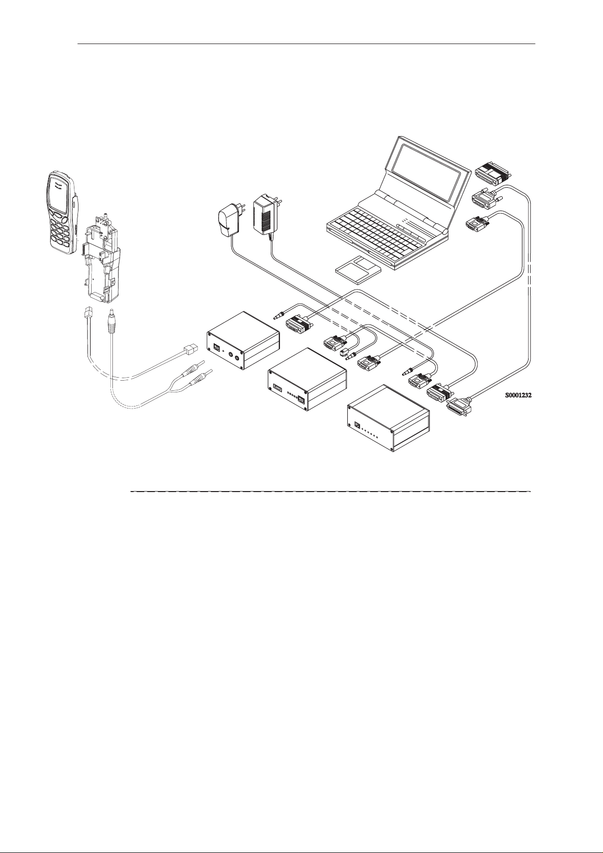
Equipment Setup for Tuning a Phone without Removing Covers
6
4.
1
5.
2
Item: Service accessory: Product
code:
1 Service Interface Cable TDS–7 0770160
2 DC Cable PCS–1 0730012
3 Service MBUS Cable DAU–9S 0730108
4 Software Protection Key PKD–1 0750018
5 Service SW Disk 3.5 0774080
3.
6 RF Coaxial Test Cable 4626009
Note: Nominal operating voltage range for TDS–7 is 9–15VDC
Issue 1 07/99
Page 9
Page 10
NSE–8/9
PAMS
Service Software
Flash Concept for NSE–8/9 (covers on)
13.
12.
6.
5.
4.
11.
Technical Documentation
10.
9A.
7.
9B.
8.
1.
14
2.
3.
Item: Service accessory: Product code:
1 Flash Loading Adapter FLA–5 0080178
2 Flash Security Box TDF–4 0770106
3 Prommer FPS–4S 0085095
4 Service Interface Cable TDS–7 0770160
5 Modular Cable XMS–3 0730174
6 DC Cable PCC–1B 0730053
7 D15 – D15 Cable AXS–5 0730091
(Included in FLA–5 sales pack)
8 Printer Cable (Included in FPS–4 sales pack) 0730029
9A D9 – D9 Cable AXS–4 0730090
(Included in FPS–4 sales pack)
9B D9 – D9 Cable AXS–4 0730090
10 Software protection key PKD–1 0750018
11 Service SW diskette 3.5” 0774080
12 Travel Charger ACH–6E (Euro) 0270381
Travel Charger ACH–6U (USA/Japan) 0270382
Travel Charger ACH–6X (UK) 0270380
13 AC Charger ACL–3E (part of FPS–4 kit) 0680015
14 DC Cable PCS–1 0730012
Page 10
Issue 1 07/99
Page 11
PAMS
NSE–8/9
Technical Documentation
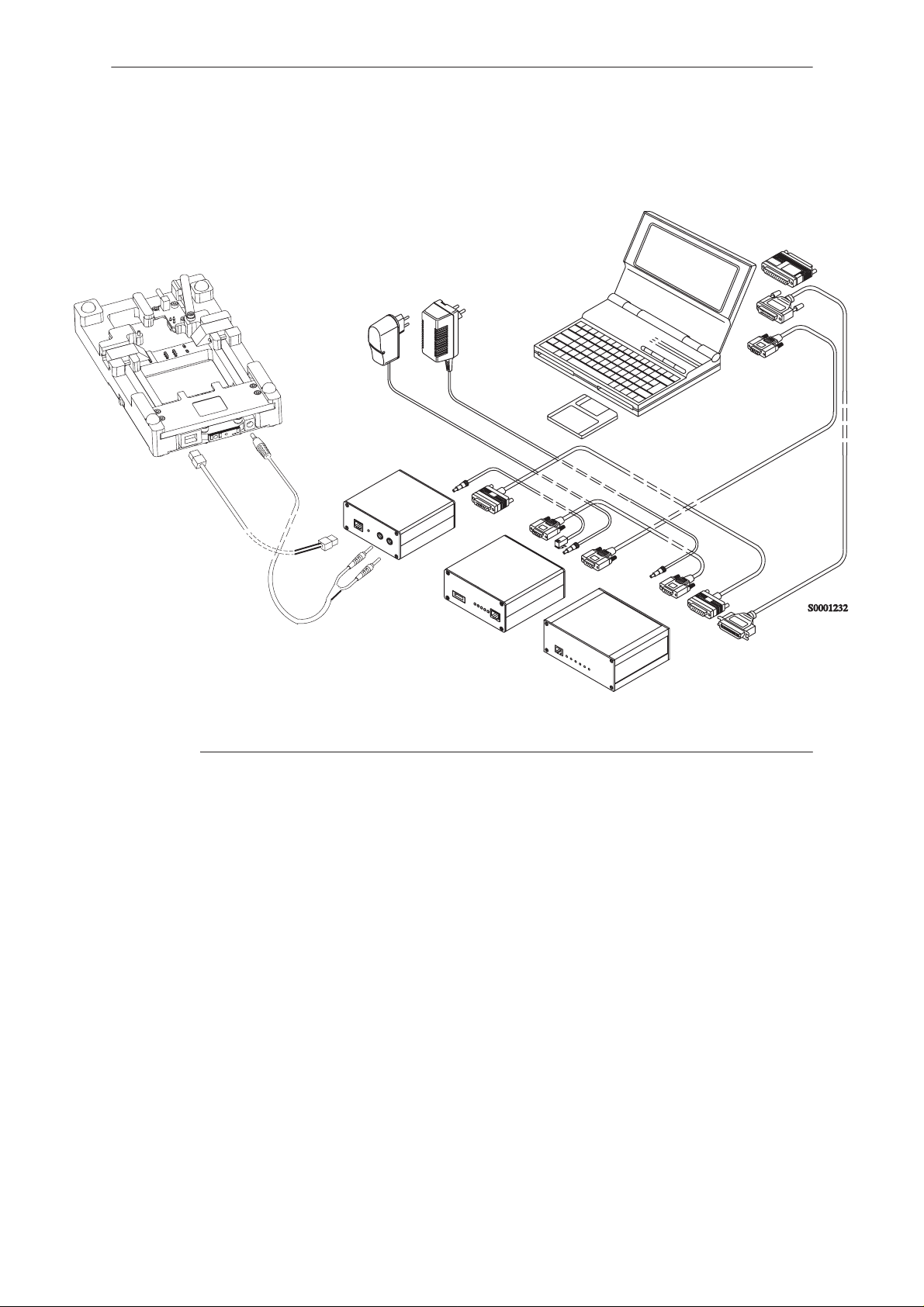
Flash Concept for NSE–8/9 (covers off)
4.
5.
12.
13.
6.
11.
Service Software
9A.
7.
9B.
10.
8.
1.
14
Item: Service accessory: Product code:
1 Flash Loading Adapter FLA–5 0080178
2 Flash Security Box TDF–4 0770106
3 Prommer FPS–4S 0085095
4 Service Interface Cable MJS–13 0770158
5 Modular Cable XMS–3 0730174
6 DC Cable PCC–1B 0730053
7 D15 – D15 Cable AXS–5 0730091
(Included in FLA–5 sales pack)
8 Printer Cable (Included in FPS–4 sales pack) 0730029
9A D9 – D9 Cable AXS–4 0730090
(Included in FPS–4 sales pack)
9B D9 – D9 Cable AXS–4 0730090
10 Software protection key PKD–1 0750018
11 Service SW diskette 3.5” 0774080
12 Travel Charger ACH–6E (Euro) 0270381
Travel Charger ACH–6U (USA/Japan) 0270382
Travel Charger ACH–6X (UK) 0270380
13 AC Charger ACL–3E (part of FPS–4 kit) 0680015
14 DC Cable PCS–1 0730012
2.
3.
Issue 1 07/99
Page 11
Page 12

NSE 8/9
PAMS
Service Software Instructions
Tuning With Covers Off
4
1.
Technical Documentation
8.
9.
3.
6.
7.
5.
2.
Item: Service accessory: Product code:
1 Module Jig MJS–13 0770158
2 Service Audio Box JBA–4 0770094
3 DC Cable PCS–1 0730012
4 RF Coaxial Test Cable 4626009
5 Audio Test Cable SCB–5 0775211
6 Service MBUS Cable DAU–9S 0730108
7 Audio Cable ADS–1 0730011
Page 12
8 Software Protection Key PKD–1 0750018
9 Service SW diskette 3.5 0774080
Note The nominal operating voltage for MJS–13 is 9–15VDC
Issue 1 07/99
Page 13

PAMS
NSE 8/9
Technical Documentation
Warranty Transfer
Service Software Instructions
2
1
Item: Service accessory: Product code:
1 Warranty Transfer Tool SCW–1 0770161
(2pcs reqd.)
2 Modular T Adapter 4626134
Issue 1 07/99
Page 13
Page 14

NSE 8/9
PAMS
Service Software Instructions
Tuning Steps
1. RX Calibration (AGC + AFC)
Procedure
Follow the steps described in chapter ”Service Software Instructions”
section ”RX calibration... command”.
Software reports the following:
AFC init value
AFC slope
PSW slope
AGC DAC values and the corresponding voltages for each gain step (0 57 dB)
Technical Documentation
Limits for the reported values
If everything went well the reported values should approximately be the
following:
Parameter Low limit High limit
AFC init value –80 80
AFC slope 130 230
PSW slope 250 350
AGC 0 dB 400 640
AGC 57 dB 100 300
Difference between the two neighbour
AGC steps
10 20
Troubleshooting
If the calibration does not succeed the software normally reports ”Unable
to read data from phone” or ”Failed to set high reference” or ”Failed to set
low reference”.
Page 14
In this case check first the basic functionality of the receiver chain: RF
generator frequency set as in the calibration and level for example to the
high reference value.
Then go to the RSSI reading menu (under RF controls). If the reading is
very low there is something broken in the receiver and must be found by
measuring voltages and signal levels at different places (information of
these can be found elsewhere in this manual).
Issue 1 07/99
Page 15

PAMS
NSE 8/9
Technical Documentation
If the RSSI reading seems to be within 5 - 10 dB the same as the RF input
level check that the VCTCXO (G650) frequency is close enough the
wanted frequency. This is most easiest done by measuring the UHF VCO
(G550) frequency because the absolute value of the deviation is biggest
there. In the GSM mid channel the UHF–VCO frequency should be 2040.0
MHz. If the deviation is bigger than about +/–20 kHz it is probable that the
VCTCXO is not operating correctly.
If both of these (RSSI reading and the frequency) seem to be correct and
calibration still fails the most probable reason is that there is a little lack of
gain somewhere or the AGC gain control slope in N600 is out of the limits.
This can be verified by changing the generator reference levels from the
demanded ones in the calibration procedure in 1 dB steps up and down. If
the calibration goes through with some reference levels the corrective
action is most probably changing N500 or N600.
Service Software Instructions
2. Alignment of Transmitter Power Levels
Equipment:
– Pulsed power meter or spectrum analyzer and 10 dB attenuator.
– MSJ–13 voltage source within 9–15VDCV.
The following settings for the spectrum analyzer are recommended when
aligning the power levels: zero span, resolution and video bandwidths 1
MHz, input attenuation 40 dB, sweep time 1 ms, video triggering.
Procedure:
Follow the instructions given in chapter ”Service Software Instructions”
section ”TX power... command”.
For GSM the alignment channel is 60 (902 MHz) and for PCN 700
(1747.8 MHz).
Issue 1 07/99
Page 15
Page 16

NSE 8/9
Á
Á
Á
Á
Á
Á
Á
Á
Á
Á
Á
PAMS
Service Software Instructions
Targets in dBm:
Power level GSM PCN
0
ÁÁÁÁ
1
2
3
4
5
6
7
8
9
ÁÁÁÁ
10
11
Technical Documentation
ББББББÁББББББ
32.5
31
29
27
ББББББ
25
ББББББ
23
21
29.5
28
26
24
22
20
18
16
14
12
10
8
12
13
14
15
16
17
18
ÁÁÁÁ
19
ÁÁÁÁ
Base
ББББББ
ББББББ
0.06 below lowest
power coefficient
19
17
15
13
11.5
10
8.5
7
6.5
5
3.5
2
ББББББ
ББББББ
0.06 below lowest
power coefficient
– Align the three levels.
– Switch off base level calculation and re–calculate.
– Set baselevel coefficient to 0.06 below the lowest coefficient.
– Check that the power is within 0.5dB from target, adjust if not.
Page 16
Issue 1 07/99
Page 17

PAMS
NSE 8/9
Technical Documentation
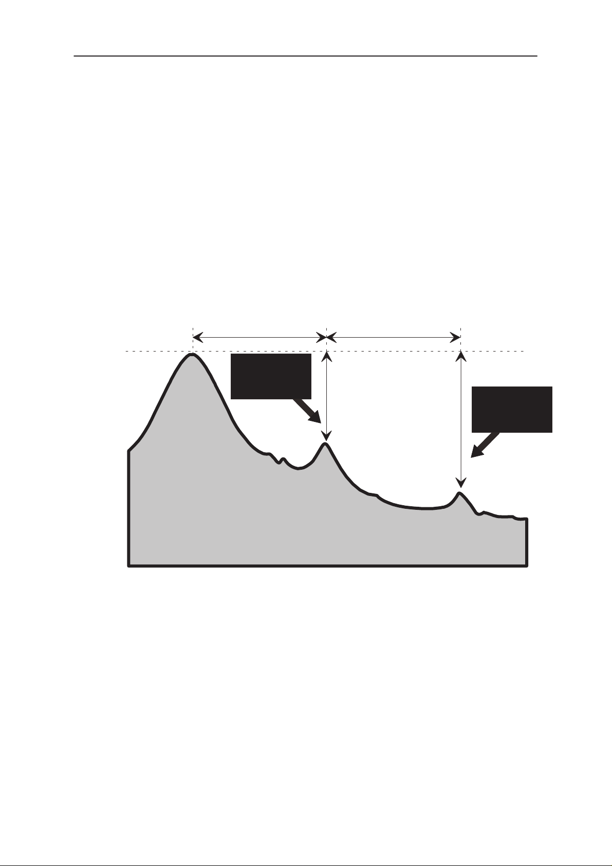
3. I/Q Modulator Alignments
I/Q modulator alignments are performed in PCN band. If GSM band has
been selected and I/Q alignment is started, the service software asks to
change to PCN band. If the user wants to continue in GSM, the adjusted
values can only be saved to PC memory, not to phone’s EEPROM. After
changing to PCN band values from PC memory are available, and if the
modulator adjustment is good, also the values can be saved to phone’s
EEPROM. See chapter ”Service Software Instructions” and section ”TX
I/Q... command” for further information.
Procedure:
Connect the spectrum analyzer to the phone antenna connector. The
recommended spectrum analyzer settings are: span 200 kHz, resolution
BW 10 kHz, video BW 1 kHz, sweep 500 ms, input attenuation 30 dB.
– From
– Go to
(1747.8 MHz).
RF controls
TX I/Q tuning
menu make sure that TX data type is 1.
menu. The alignment channel for PCN is 700
Service Software Instructions
– Select the ”TX I DC offset” option and adjust the level of the centre fre-
quency (CHF) to minimum.
– Select the ”TX Q DC offset” option and adjust the level of the CHF
again to minimum.
– After finding both minima change ”TX I DC offset” by step or two from
the current value to both directions to see, whether better minimum
can be found for CHF.
– Select the ”Amplitude Difference” option and adjust the level of the un-
wanted sideband CHF + 67.71 kHz to minimum.
– Select the ”Phase Difference” option and dajust the level of CHF +
67.71 kHz again to minimum.
– After all the minima have been found press ”Save” button to store the
values to phone EEPROM.
Targets:
The level of the centre frequency CHF should be at least 30 dB down to
the wanted sideband CHF - 67.71 kHz.
The level of the unwanted sideband CHF + 67.71 kHz should be at least
35 dB down to the wanted sideband CHF - 67.71 kHz.
Issue 1 07/99
Page 17
Page 18
NSE 8/9
PAMS
Service Software Instructions
Alignment verification in GSM band:
– Go to
Product ––> Initialize ––> Normal mode
a SW reset for the phone. Which in turn is needed to get the aligned
I/Q values in use.
– Go to
– Go to
Product ––> Band ––> GSM
RF controls
level 10, TX data type 1.
– Check the levels of CHF and CHF + 67.71 kHz. Both the levels
should be at least 30 dB down to the wanted sideband CHF - 67.71
kHz. If both or either of the specifications is not met adjust the required
values (I and Q DC offsets for CHF and amplitude and phase for CHF
+ 67.71kHz) to meet the specifications.
Technical Documentation
. This is needed to give
menu and start transmission on channel 60, power
–67.71 kHz +67.71 kHz
D.C. offset
tunings:
Set this value
to minimum
CHF
> 30 dB
> 35 dB
Amplitude &
phase difference:
Set this value
to minimum
Page 18
– Store the results in PC memory.
– Go to
Product ––> Band ––> PCN
and then to
TX I/Q Tuning
to check
the alignment with the values which are in PC memory. If the specifications are not met in PCN the solution is to find compromise values
which are not optimum for either bands but still meet the specifications.
– If the PCN band alignment is good with the values from PC memory,
the TX I/Q tuning procedure can be stopped by pressing the ”Save”
button.
Issue 1 07/99
Page 19

PAMS
NSE 8/9
Technical Documentation
4. Energy Management Calibration
Equipment
– Voltage source – within 9–15VDC range.
– MJS–13 Module Repair Jig.
Procedure
– Connect power supply to MJS–13.
– Start up WinTesla.
– Set switch on MSJ–13 to ( local position)*
– Choose
– Select no.2
– Press
– Press OK to save
Tuning
Battery Voltage
Run.
menu and then
and no.3
Battery Voltage.
Service Software Instructions
Energy Management Calibration.
Charger Voltage.
– Press OK to save
* MJS–13 supplies the system board with 8.4VDC via X5 pin 11, when the
test switch is in (local position).
Charger Voltage.
Issue 1 07/99
Page 19
Page 20

NSE 8/9
PAMS
Service Software Instructions
Common User Interface
All WinTesla files share a common interface which are detailed in the
WinTesla help files once the software is installed. A typical example is
shown in the figure below.
Technical Documentation
Page 20
Issue 1 07/99
Page 21

PAMS
NSE 8/9
Technical Documentation
NSE–8 Features
Product
New command
Activation Status Bar Text
Alt, P, N Rescan a new phone
Ctrl+R
If phone is changed (with same phone type only serial number is
changed) phone will be initialised. If phone is changed to different phone
type the current DLLs are unloaded and new ones are loaded for that
phone.
If the Quick/RF Info view is open, window will be automatically updated. If
Phone Information view is open, it will be automatically updated.
Service Software Instructions
pen... command
O
Activation Status Bar Text
Alt, P, O Force load phone specific functionality
Phone is set to normal mode.
I
nitialise... command
Activation Status Bar Text
Alt, P, I
Opens a submenu
Normal Mode
Activation Status Bar Text
Alt, P, N Initialises phone to normal mode
F5
When normal mode has been activated or program has been started,
self–test results will be asked from MCU. If any fault was found in the
tests, an error message is shown. If normal mode has been set
successfully (no self test error has been found), and paging listening has
been started, the used AFC value is requested from MS. Initialisation
routine checks phone’s cellular type and if unsupported phone is detected,
application unloads the DLLs.
Issue 1 07/99
Page 21
Page 22

NSE 8/9
PAMS
Service Software Instructions
The After Sales SW sets automatically the MS state to local mode when
needed. If phone identification view is open, window will be automatically
updated. Also if RF Information Window is open it will be updated to quick
info view.
ocal Mode
L
Activation Status Bar Text
Alt, P, L Initialises phone to local mode
Shift+F5
Selection will change the MS state to
Testing or Tuning menus, the After Sales SW software will change
automatically the MS state to local.
The After Sales SW sets automatically the MS state to local mode when
needed.
Technical Documentation
local
. When user selects item from
Also if quick info view is open it will be updated to RF Information view.
and command
B
Activation Status Bar Text
Alt, P, B
Opens a submenu
SM
G
Activation Status Bar Text
Alt, P, B, G
Selects the GSM band on the MS
CN
P
Activation Status Bar Text
Alt, P, B, P
Selects the PCN band on the MS
aultlog command
F
Activation Status Bar Text
Alt, P, F
Opens a submenu. Only enabled when a user has logged in.
Page 22
Issue 1 07/99
Page 23

PAMS
NSE 8/9
Technical Documentation
Activate Faultlog
Activation Status Bar Text
Alt, P, F, A
F9
Activates the faultlog. Only enabled when a user has logged in.
dit Faultlog
E
Activation Status Bar Text
Alt, P, F, A
Allows user to edit faultlog entries. Only enabled when a user has logged
in.
FastNAM command
Service Software Instructions
Activation Status Bar Text
Alt, P, N
F8
This menu is only enabled when FastNAM functionality is included in Win
Tesla.
FLS–1 Remote Update command
Activation Status Bar Text
Alt, P, 1
This menu is only shown if the FLS–1 License Update Control Centre
program has been installed into the WinTesla directory.
With this program it is possible to request and update the number of flash
licenses in the FLS device.
it command
Ex
Activation Status Bar Text
Alt, P, X
Exits the WinTesla application.
Issue 1 07/99
Page 23
Page 24

NSE 8/9
PAMS
Service Software Instructions
Tuning
The tuning menu offers functions for ME adjustments.
R
X Calibration... command
Activation Status Bar Text
Alt, T,R Open RX Calibration dialog box
Starts RX calibration.
When calibrating the RX it is nessessary to first calibrate in GSM and then
in PCN. WinTesla will automatically change to GSM if the calibration is
started in PCN.
Technical Documentation
The next automatic selections are made when this tuning function is
activated:
• Phone is set to local mode
• Update RF information window
The measurement is started automatically when RX calibration is entered.
The measurement is done in five steps:
1. User is requested to put signal generator to high input level (read from
Tesla .INI file).
2. Measurement with high input level is executed
3. User is requested to put signal generator to low input level (read from
Tesla .INI file).
4. Measurement with low input level is executed
Page 24
Issue 1 07/99
Page 25

PAMS
NSE 8/9
Technical Documentation
5. The RX Calibration dialog will be updated when previous steps are
done.
Service Software Instructions
Dialog mode: modal
RX Calibration dialog has the following items:
AFC information box:
Shows AFC init value, AFC slope and PSW slope values.
AGC List box (ALT+A):
Issue 1 07/99
Page 25
Page 26

NSE 8/9
PAMS
Service Software Instructions
AGC, DAC, Voltage and Difference. The difference column shows the
difference between tuned DAC values and mean straight line calculated
from part slopes in dBs (see /1/). This can be calculated when all
measurement results have been received from phone.
Repeat button (ALT+R):
The measurement can be started again by pressing this button.
Save button (ALT+S):
Dialog is closed and tuning
Cancel button (ESC):
Dialog is closed and tuning
When calibration is ended, the DAC value checking is made and if it is not
succeeded, error message is shown.
When exit is made, the next selections are set to the values which were
selected before this adjustment.
is saved
to phone.
is not saved
Technical Documentation
to phone.
The exit and the use of AGC–control values is done same way as exit
from power level tuning and power coefficient use:
ower... command
Tx P
Activation Status Bar Text
Alt, T,P Open TX Power Tuning dialog box
Starts TX power tuning.
Before the TX power tuning starts the DC/DC converter is set to the mode
specified in TESLA.INI in the section:
[NSE–8TXPOW]
DC2DC_Startup=2 ;0=Auto Mode 1=Abs Mode and 2=Max
Mode
Max Mode is the default mode set at installation time and is recommended
because it will ensure, that the phone will not shut down due to too big
supply voltage drops when tuning the higher power levels.
Operation Mode
Update RF Information window
Page 26
Issue 1 07/99
Page 27

PAMS
NSE 8/9
Technical Documentation
Then the user is requested to select in the Start Tuning dialog which
tuning values to use. If the Start Tuning dialog is not shown the tuning will
use the EEPROM values directly.
Start Tuning dialog has following items:
Start Tuning With list box (ALT+S):
Current Values in PC memory
Service Software Instructions
Tuning values are load from program’s internal memory.
EEPROM Values
Tuning values are load from ME’s EEPROM.
Factory Default Values
Tuning values are load from ME’s flash.
The next automatic selections are made when this tuning function is
activated:
the lowest power level is selected
Operation mode = TX pulsed
Issue 1 07/99
Page 27
Page 28

NSE 8/9
PAMS
Service Software Instructions
The TX Power Tuning dialog will be activated automatically after value
selection.
Technical Documentation
Dialog mode: modal
TX Power Tuning dialog has following items:
Power Level & Coefficients list box (ALT+L):
The power is presented in GSM or PCN values. The test value is not
saved to the EEPROM. The test value can be changed during tuning as
other power coefficients and the program remembers its value when
tuning function is activated later again.
If there is more power levels in the phone that can fit into window the
window is scrollable. When phone is initialised the program asks the
number of power levels used in the phone.
Only three power coefficients (highest, third smallest and lowest) are
needed to tune (left justified Coefficients) and the rest of them are
calculated.
The highlighted tuning position can be tuned with +/– keys or left/right
cursor keys.
Calculate button (ALT+C):
The calculation is activated with this button. The power coefficients which are
calculated from the tuned coefficients are displayed.
Page 28
Issue 1 07/99
Page 29

PAMS
NSE 8/9
Technical Documentation
Base level calculation check box:
If this box is checked the base level is calculated.
+/– buttons (+/– and left/right cursor keys):
+ and – buttons will cause power changing by 0.25dB steps. When these
keys are used the coefficient value is updated on the tuning window.
Save button (ENTER):
Dialog is closed and tuned values are
Cancel button (ESC):
Dialog is closed and tuning
When selections are used, the power value checking is made and if it is
not succeeded, error message is shown. The test checks that all power
coefficients are in descending order (same order than power levels).
Service Software Instructions
saved
is not saved
to phone.
to phone.
If the power tuning function is ended and EEPROM values are not
received or EEPROM fault is noticed, an error message is shown.
When all power coefficients have such values that they don’t cause any
error messages, save can be made. The last used tuning power is in use
after exit.
The next automatic selection is made when this tuning function is ended:
Operation Mode = RX pulsed
When the tuning dialog is closed the DC/DC converter is set to the mode
specified specified in TESLA.INI in the section:
[NSE–8TXPOW]
DC2DC_Exit=0 ;0=Auto Mode 1=Abs Mode and 2=Max
Mode
Auto Mode is the default mode set at installation time.
Issue 1 07/99
Page 29
Page 30

NSE 8/9
PAMS
Service Software Instructions
Tx I/Q... command
Activation Status Bar Text
Alt, T,Q Open TX I/Q Tuning dialog box
This function is used for tuning TX I and Q branch DC offset, amplitude
difference and phase difference.
It is not possible to tune TX I/Q in GSM. WinTesla will automatically
change to PCN if the calibration is started in GSM.
Technical Documentation
Then the user is requested to select in the Start Tuning dialog which
tuning values to use. If the Start Tuning dialog is not shown the tuning will
use the EEPROM values directly.
The next automatic selections are made when this function is activated:
Operation Mode = TX pulsed
Update RF Information window
The TX I/Q Tuning dialog is opened.
Page 30
Issue 1 07/99
Page 31

PAMS
NSE 8/9
Technical Documentation
Dialog mode: modal
TX I/Q Tuning has following items:
Tune TX I
Tune TX Q
Tune A
DC Offset scroll bar (ALT+I):
The DC Offset is shown as percents (%) from the ± maximum
value. 0% means that there is no DC. The value range is
–100%...100%. The value is rounded to the nearest integer
value.
DC Offset scroll bar (ALT+Q):
The operation of this function is the same as one above, except
with this selection the Q branch DC Offset is tuned. The value
range is –100%...100%. The value is rounded to the nearest
integer value.
mplitude Difference scroll bar (ALT+A):
Service Software Instructions
When this selection is made user can increase or decrease the
amplitude difference within 0.1 dB steps. The value range is
–1...1.
Tune P
Save button (ENTER):
Cancel button (ESC):
After each value change the new value is sent to the phone.
The next automatic selection is made when TX I / Q tuning function is
ended:
hase Difference scroll bar (ALT+P):
When this selection is made user can increase or decrease the
phase difference within 0.5° steps. The current phase difference
is shown on the tuning window with numbers and bar figure.
The value range is –85...90.
Dialog is closed and tuning
Dialog is closed and tuning
Operation Mode = RX pulsed
is saved
is not saved
to phone.
to phone.
Issue 1 07/99
Update RF Information window
Page 31
Page 32

NSE 8/9
PAMS
Service Software Instructions
Energy Management Calibration... command
Activation Status Bar Text
Alt, T,E Energy Management Calibration
This command opens the Energy Management Calibration dialog box:
Technical Documentation
Page 32
The Energy Management Calibration dialog box contains the following
options:
Run button (ALT+R):
The selected energy management calibrations are performed,
Close button (ENTER):
The dialog box is closed without performing energy
management calibration.
Help button (ALT + H):
Displays context sensitive help.
Issue 1 07/99
Page 33

PAMS
NSE 8/9
Technical Documentation
The settings to be selected are:
1. Run battery & charger default values checkbox (ALT+1):
Loads battery & charger default values to phone when selected.
2. Battery voltage checkbox (ALT+2):
Calibrates battery voltage A/D value.
3. Charger voltage checkbox (ALT+3):
Calibrates charge voltage A/D value.
The user is asked to connect the correct charging voltage and current
limit.
4. VDC Out (DC/DC) checkbox (ALT+7)
Calibrates the VDC Out voltage from the DC/DC converter.
This calibration is special for the NSE–8 phone. When this calibration is
executed a VDC Out input field is shown. The voltage must be measured
and entered into this field and then the Calibrate button completes the
calibration.
Service Software Instructions
Issue 1 07/99
Page 33
Page 34

NSE 8/9
PAMS
Service Software Instructions
DC/DC Tuning Command
Activation Status Bar Text
Alt, T,D DC/DC (Vdc_out) tuning
This command opens the DC/DC Tuning dialog box.
This dialog box allows you to set the DC/DC mode used and to check the
different voltage levels for the all power levels when in Auto mode.
The tuning is done for the currently selected band (GSM/PCN).
The modeless RF Information window is opened.
OK button:
The dialog is closed and the selected mode will be preserved.
Cancel button:
Technical Documentation
The dialog is closed and the mode used before starting the
DC/DC tuning is restored.
Page 34
The DC/DC converter can be set to 3 different modes. When opening the
DC/DC tuning dialog the currently used mode is shown.
1) Auto mode.
The Auto mode is the default mode and is active when the phone powers
up and after a reset. When the phone is in automatic mode the DC/DC
output voltage is changed by the phone itself.
Issue 1 07/99
Page 35

PAMS
NSE 8/9
Technical Documentation
This is done to save power. In standby, idle and the lower power levels the
voltage is low and only when transmitting on the higher power levels, the
vibrator is on or the buzzer is on is a high output voltage required.
When Auto mode is selected the phone is set to the TX power level
highlighted in the listbox. The phone will set the DC/DC output voltage
according to the VDC Out value shown.
Changing the selected power level can test the DC/DC converter in Auto
Mode.
2) Max mode
In maximum output voltage mode the DC/DC converter constantly
supplies the highest possible voltage. Only changing mode or resetting
the phone will change the voltage level.
3) Abs mode
In absolute output voltage mode the DC/DC converter constantly supplies
the voltage level requested by the user. Only changing the requested
voltage level, mode or resetting the phone will change the voltage level.
Service Software Instructions
The voltage level can be entered directly and is limited to the range from
3volt to 4.49volt. The phone set the DC/DC output voltage to the nearest
possible value when clicking on the Apply button.
Issue 1 07/99
Page 35
Page 36

NSE 8/9
PAMS
Service Software Instructions
Testing
The Testing sub menu offers functions for ME testing.
R
F Controls... command
Activation Status Bar Text
Alt, E,R Open RF Controls dialog box
This function is used for RF testing.
Command opens RF Controls dialog, which contains data for testing and
adjustments.
Technical Documentation
Page 36
Dialog mode: modal
RF Controls dialog has following items:
Active Unit group:
RX radio button (ALT+R):
RX
When
is selected, the next functions are made:
Data transmission is deactivated
TX power is deactivated
If operation mode is continuous,
– AGC is controlled
– RX continuous mode channel is activated
Issue 1 07/99
Page 37

PAMS
NSE 8/9
Technical Documentation
RF Information window is updated
The RX value is always given as default.
Note! Function is activated immediately, Apply is not needed.
TX radio button (ALT+T):
TX
When
is selected, the next functions are made:
Data transmission is activated
If operation mode is continuous,
– Operation mode is set to burst
RF Information window is updated
Continuous mode radio button is disabled.
Note! Function is activated immediately, Apply is not needed.
Service Software Instructions
Operation Mode group:
Continuous radio button (ALT+C):
When
continuous
selection is used,
synthesiser is set to constant frequency
synthesiser channel number is as given with Continuous Mode
Channel selection
transmitter power is not connected
if Active Unit is RX, AGC is controlled
Note! Function is activated immediately, Apply is not needed.
Issue 1 07/99
Page 37
Page 38

NSE 8/9
PAMS
Service Software Instructions
Burst radio button (ALT+B):
burst
When
selection is used,
synthesiser is controlled by using
receiving/transmission/measuring synthesiser control sequence
synthesiser channel numbers are as given with
Channel/Monitoring Channel selections
if Active Unit is TX, data (selected with TX Data Type) is sent
and the TX power is connected
Note! Function is activated immediately, Apply is not needed.
TX Data Type drop list (ALT+D):
TX Power Level edit box (ALT+T):
It is possible to change the transmission power in TX mode. The user can
select the needed power value or select the test value, which is tuned with
TX power tuning function. The test value is found at the end of the list.
Technical Documentation
TX Power have value
and is disabled (
greyed
) when active unit is
OFF
RX. When the TX power is tuned with test value (smallest value) the TX
TEST
Power has value
.
Continuous Mode Channel edit box (ALT+C):
Here the user can enter the continuous mode channel which may have all
channel numbers. The used frequency depends on the Active Unit. If
Active Unit is RX, then RX frequency is used, else TX frequency. The
frequency of the selected channel is shown after selection.
annel edit box (ALT+H):
Ch
Here the user can enter the channel number that is used for both
transmission and receiving. The frequency of the selected channel is
shown.
Monitoring Channel edit box (ALT+M):
This field selects the neighbour monitoring channel. The frequency of the
selected channel is shown.
AGC A
bsolute edit box (ALT+A):
Page 38
This selection allows user to edit AGC absolute value (value from A/D
converter). When AGC Absolute value is changed the AGC dB value will
be calculated depending on the AGC Absolute value.
Front End On check box:
This selection allows user to change whether the Front End amplifier is On
or Off.
Issue 1 07/99
Page 39

PAMS
NSE 8/9
Technical Documentation
AGC edit box (ALT+G):
This selection allows user to edit the AGC dBvalue. The AGC value is
shown only when its value is controlled by PC. When Active Unit has
value RX and Operation Mode is continuous, AGC is controlled by PC
except when next adjustment functions are activated:
RSSI Calibration
AFC Diagram
Apply button (ALT+A):
Accepts entered values and validates them. After validation all values are
sent to ME and the RF information window is updated.
Note! Active Unit and Operation mode are not included because they are activated
immediately.
Set Defaults button (ALT+S):
Service Software Instructions
Sets current values shown as default RF Controls values. Stores the
values in
Tesla.ini
Get Defaults button (ALT+G):
Gets default RF Controls values from the
Tesla.ini
file and shows them.
The next automatic selection is made when Quick testing function is
ended:
Active Unit = RX
Update RF Information window
The next table shows the dialog’s properties on different situations:
ACTIVE UNIT = TX:
TX Data Type: Updated
AGC values: Greyed
Monitoring Channel: Greyed
OPERATION MODE = BURST:
ACTIVE UNIT = RX:
Issue 1 07/99
TX Power Level: Updated
Continuous Mode Channel: Greyed
Channel: Updated
TX Data Type: Greyed
TX Power Level: OFF, Greyed
Page 39
Page 40

NSE 8/9
PAMS
Service Software Instructions
OPERATION MODE = BURST:
AGC values: Greyed
Continuous Mode Channel: Greyed
Channel: Updated
Monitoring Channel: Updated
OPERATION MODE = CONT:
AGC values: Updated
Continuous Mode Channel: Updated
Channel: Greyed
Monitoring Channel: Greyed
RSSI Re
ading... command
Technical Documentation
Activation Status Bar Text
Alt, E,R read continuously RSSI value
Command opens RSSI Reading dialog:
Dialog mode: modal
RSSI value is read continuously until user presses ESC–key or Close
button to cancel reading.
Page 40
RSSI Reading dialog has following items:
Close (ENTER) button:
Closes the RSSI Reading dialog. Does not send anything to
phone.
H
elp button:
Context sensitive help.
Issue 1 07/99
Page 41

PAMS
NSE 8/9
Technical Documentation
Self Tests... command
Activation Status Bar Text
Alt, E,S Open MCU Self–tests dialog box
Command is used for reading self test results and running self tests.
When the selection is made, the test result is read from ME. The test
result will be shown to the user within MCU Self–test dialog.
Service Software Instructions
Dialog mode: modal
MCU Self–test dialog has following items:
Tests list box (ALT+T):
The field ”(p)” in the screen example means that the test is also run in
power up. The field “(/s)” means that this test is selectable one.
Test states are updated according to results received from the phone.
Possible test states will be one of the next:
Passed
Failed
No response
Not executed
Issue 1 07/99
Page 41
Page 42

NSE 8/9
PAMS
Service Software Instructions
Not valid
RUNNING....
Note that power–off test have no values, because if test has been passed, power has
been turned off. If power–off test fails a special error message window is shown. If no
response is received to power off test message in a few seconds, the user is informed by
special info window, where user is asked to turn the power on and then press the return
key.
Note also that power–off test (if passed) turns power off and power should be
reconnected by using the phones keypad after the successful test. After the power has
been connected to phone, the normal start–up routines are made and the self–test
results are shown in the MCU self–tests menu (i.e. all other than power–up self–tests are
in Not executed state after the power–up routines).
Run button (ALT+R):
User can select desired test from list and hit Run button. When user
selects test to be run the text
test is run. When results are received the test state field is updated
according to the result.
RUNNING...
Technical Documentation
is shown in test state field and
If no response was received in the defined time, a
be shown and the test state is changed to
local mode if it is not already there.
Run A
ll button (ALT+A):
User can run all listed tests. The text
field and test is run. When results are received the test state field is
updated according to the result. When state field is updated application
moves to next test and repeats previous cycle. Phone is set to local mode
if it is not already there.
Supported Self Tests
The following tests are available:
1 MCU ROM Checksum................
2 MCU RAM Interface...............
3 MCU RAM Component...............
4 MCU EEPROM Interface............
5 MCU EEPROM Component............
No response
RUNNING...
error message box
will
. Phone is set to
is shown in test state
Page 42
6 Not Used.....................
7 CCONT Interface.................
8 A/D Converter...................
9 SW Reset........................
A Power Off.......................
Issue 1 07/99
Page 43

PAMS
NSE 8/9
Technical Documentation
B Security Data...................
C EEPROM Tune Checksum............
D PPM Checksum....................
E MCU Download DSP................
F DSP Alive.......................
G COBBA Serial.......................
H COBBA Parallel.....................
I EEPROM Sec Checksum................
J PPM Validity..................................
K Warranty State..............................
A
DC Readings... command
Service Software Instructions
Activation Status Bar Text
Alt, E,A Open ADC Readings dialog box.
Command is used to read and show A/D values from phone.
Command opens ADC Readings dialog.
Dialog mode: modal
The ADC Readings are updated every second.
ADC Readings dialog has following items:
Close (ENTER) button:
Closes the ADC Readings dialog. Does not send anything to phone.
Help button: Context sensitive help.
Following A/D values are measured:
Issue 1 07/99
Page 43
Page 44

NSE 8/9
PAMS
Service Software Instructions
Battery Voltage.........:
Battery Temperature.....:
Charge Voltage..........:
Charge Current..........:
PSCC Voltage............:
Acessory Detection......:
VDC Out...................:
VCXO Temperature........:
Hook Informaton........:
dio... command
Au
Activation Status Bar Text
Alt, E,U
Technical Documentation
Opens a submenu which contains following options:
Internal Audio Loops
Activation Status Bar Text
Alt, E,U,I Open Internal Audio loops dialog box.
Command is used for making internal audio loop tests in Internal Audio
Loops dialog.
Page 44
Issue 1 07/99
Page 45

PAMS
NSE 8/9
Technical Documentation
Dialog mode: modal
Internal Audio Loops dialog has following items:
Buzzer group:
Next three different values can be selected for Buzzer:
Volume On radio button (ALT+V):
Turns buzzer on.
Volume O
Level drop down list (ALT+L):
Frequency edit box
ff radio button (ALT+O):
Turns buzzer off.
Sets level of a buzzer. Allowed range 0...127
Sets the sound frequency
Service Software Instructions
Internal Audio Loop group:
Input group:
Next three different values can be selected for input:
Internal radio button (ALT+I):
Turns internal input.
External radio button (ALT+I):
Turns external input.
dset radio button (ALT+A):
Hea
Turns headset input.
Output group:
Next two different values can be selected for output:
ernal radio button (ALT+T):
Int
Turns internal output.
ternal radio button (ALT+X):
Ex
Headset radio button (ALT+D):
Issue 1 07/99
Turns external output.
Turns headset output.
Page 45
Page 46

NSE 8/9
PAMS
Service Software Instructions
Loop group:
Next two different values can be selected for loop:
Off
radio button (ALT+F):
Turns audio loop off.
On
radio button (ALT+N):
Turns audio loop on.
When the dialog is closed, the Buzzer Volume is always switched off. Also
internal audio loop is turned off.
User Interface... command
Activation Status Bar Text
Alt, E,T Open User Interface Tests dialog box
Technical Documentation
Command is used for making display tests in Display Tests dialog.
Dialog mode: modal
Display Tests dialog has following items:
1. Test Pattern radio button (ALT+1):
In test display 1 the display is filled with chessboard letters.
2. Test Pattern radio button (ALT+2):
In test display 2 the display is filled with inverse chessboard letters.
When dialog is closed the phone LCD display is cleared.
C
all Simulation... command
Activation Status Bar Text
Alt, E,C Open Call Simulation dialog box
Command is used for making call simulation. Function opens Call
Simulation dialog.
Page 46
Issue 1 07/99
Page 47

PAMS
NSE 8/9
Technical Documentation
Dialog mode: modal
Service Software Instructions
Call Simulation dialog has following items:
TX Power Level edit box (ALT+T):
All power levels can be selected. This updates same parameter as TX
Power Level in the RF Controls dialog. Note that TEST value cannot be
selected. If TEST value was in use when Call simulation menu selected,
power level is changed to smallest value.
Channel edit box (ALT+C):
This tells the normal operating RF channel number. Normal GSM/PCN
channel numbers can be selected. Same channel is used both for
transmission and receiving. This updates same parameter as Channel in
the RF–Controls dialog.
Channel 1
Channels for monitoring are specified with these six selections. All
GSM/PCN channel numbers can be used. If more than one selection has
same number, the monitoring channel list (neighbour list) will have less
than 6 selected channels. The minimum number of monitoring channels is
one (all channels have same value). The monitoring channel can also
have same value as normal operating channel.
,2,3,4,5,6 edit box (ALT+1,2,...):
The first monitoring channel updates same parameter as Monitoring
Channel in the RF–Controls dialog.
Apply button (ALT+A):
Validates and sends entered data to ME.
Set Defaults button (ALT+S):
Sets current values as default Call Simulation values.
Issue 1 07/99
Page 47
Page 48

NSE 8/9
PAMS
Service Software Instructions
Get Defaults button (ALT+G):
Gets default Call Simulation values as current values.
Noise Sensitivity... command
Activation Status Bar Text
Alt, E,N Opens Noise sensitivity dialog box
Command is used for noise sensitivity measurement.
The next automatic selections are made when this tuning function is
activated:
– Operation mode = RX cont
– AGC = 81 dB
Before function opens Noise Sensitivity dialog application prompts:
Technical Documentation
Then application opens Noise Sensitivity dialog:
Dialog mode: modal
Noise Sensitivity dialog has following items:
Measurements group:
Page 48
Issue 1 07/99
Page 49

PAMS
NSE 8/9
Technical Documentation
Clipping distance is the difference to the signal clipping value. SNR is
measured in AD converter.
The last value on the display is signal power difference between I and Q
branch. The numbers are shown in 0.1dB accuracy. The error messages,
”OUT OF RANGE”, are shown only if the SNR and/or amplitude difference
values are not acceptable.
Signal/Noise radiobutton (ALT+S/ALT+N):
When buttons are pressed, the RX I and Q burst data is asked, text
”SIGNAL MEASURING...” or ”NOISE MEASURING...” will come to the
measurement group window. The power level value should be –92 dBm
during signal measurement.
When signal data is received, distance to clipping signal level is shown as
dBs on the display. When either signal or noise measurement results are
received ”MEASURING” text is removed and measurements are updated
to screen. When both measurements (signal and noise) are done at least
once, the signal to noise relation and difference are also shown on the
display.
Service Software Instructions
When exit is made, the next selections are set to the values which were
selected before this adjustment.
– Operation mode
– AGC value
Vibra test....command
Activation Status Bar Text
Alt, E, V Initialising phone to local mode
Command used to test vibrator functionality
Dialog mode: modal
Issue 1 07/99
Page 49
Page 50

NSE 8/9
PAMS
Service Software Instructions
Software
Product Profile... command
Activation Status Bar Text
Alt, S,P Open Product Profile settings dialog box.
Function is used for making product profile settings.
When command is activated the product profile information is read from
EEPROM and Product Profile dialog is opened.
Technical Documentation
Page 50
Dialog mode: modal
Product Profile dialog has following items:
Se
ttings list box (ALT+E):
A list where user can select desired setting.
User can toggle setting with following Options drop list or by double
clicking desired setting in list box.
Issue 1 07/99
Page 51

PAMS
NSE 8/9
Technical Documentation
Options drop list (ALT+O):
List allows user to set options to each settings which are listed in Settings
list box.
Save(OK) button (ENTER)
Selections are accepted and saved to EEPROM.
Cancel button (ESC)
Selections are ignored and control is returned back to main menu.
S
tart Up Self–tests... command
Activation Status Bar Text
Alt, S,S Open MCU start Up self–tests dialog box.
Function is used for changing the state of the EEPROM selectable tests in
MCU Start Up Self–tests dialog.
Service Software Instructions
Dialog mode: modal
MCU Start Up Self–tests dialog has following items:
Tests list box (ALT+T):
When dialog is opened, the previous values will be read from the MCU
EEPROM and shown on the list box.
Status group:
When radio button On is selected, the test will be run every time when
automatic start up self–tests are activated (e.g. in power up).
Save button (ENTER)
Selections are accepted and saved to EEPROM. A power up routine is
made to phone.
Cancel button (ESC)
Selections are ignored and control is returned back to main menu.
Issue 1 07/99
Page 51
Page 52

NSE 8/9
PAMS
Service Software Instructions
Selectable Start–Up self tests:
1. PPM Validity
3. A/D Converter
Set Factory Values... command
Activation Status Bar Text
Alt, S,V Set factory values
Application does not ask confirmation. Next kind of text will be shown to
user:
“Setting UI and SCM Factory values...”
Technical Documentation
Dialog mode: modal
Default Factory Values dialog has following items:
Settings list box:
Contains the selectable factory values.
Set button:
Sets the selected factory value to phone. Before setting software asks
confirmation:
Cancel button:
Closes the Default Factory Values dialog.
Page 52
Issue 1 07/99
Page 53

PAMS
NSE 8/9
Technical Documentation
Phone Identity... command
Activation Status Bar Text
Alt, S,I Open Phone Identity dialog box for editing
Function is used to edit phone identity. With this dialog IMEI or SIM locks
may be changed in following manner:
– current phone information is read from phone
– user edits User Name (and IMEI, Product Code and Product Id, if they
were not read correctly from phone)
– dialog information is saved to file, which is sent to secure place where
actual programming information may be constructed
– programming information is got from secure place in an other file, which
is loaded to dialog
Service Software Instructions
– program checks input values and if they are correct programming
information is written to phone
Function opens Phone Identity dialog.
Dialog mode: modal
Issue 1 07/99
Page 53
Page 54

NSE 8/9
PAMS
Service Software Instructions
Phone Identity dialog has following items:
User Name edit box (ALT+U):
Field where user can enter user identification.
IMEI edit box (ALT+I):
Field where user can enter IMEI value. Field can contain up to 40 digits.
This field is automatically filled, if ME is connected to the PC when dialog
is loaded.
Product Code edit box (ALT+P):
Field where user can enter Product Code value.
This field is automatically filled, if ME is connected to the PC when dialog
is loaded.
MS Id edit box (ALT+M):
Technical Documentation
Field where user can enter MS Id corresponding programming data. This
field is automatically filled, if ME is connected to the PC when dialog is
loaded.
Pr
oduct Id edit box (ALT+R):
Field where user can enter Product Id. This field is automatically filled, if
ME is connected to the PC when dialog is loaded.
ta edit box (ALT+A):
Da
Field where user can enter Data entry. This field is automatically filled,
when file is loaded or data is saved.
IMEI radio button:
File and ME operations contains only IMEI data.
SIM Lock radio button:
File and ME operations contains only SIM Lock data.
IM
EI Programming Data edit box (ALT+I):
IMEI programming data is read from file or entered by user to this field.
Page 54
SIM Lock Programming D
SIM Lock programming data is read from file or entered by user to this
field.
Close button (ESC):
Cancels all edits and does not save values to phone.
ata edit box (ALT+D):
Issue 1 07/99
Page 55

PAMS
NSE 8/9
Technical Documentation
Help button
Opens a help text.
Write button (ALT+W):
Writes programming data to phone. Actions are selected with Action
Selection radio button.
Read button (ALT+R):
Reads identification data from phone and shows it in dialog controls.
Needed data is selected by Action Selection radio button.
Save File... button (ALT+S):
Writes a file containing data needed by security place application to create
needed programming data. File is selected with File Save As dialog.
Load File... button (ALT+L):
Service Software Instructions
Reads a file containing data needed to program selected data. File is
selected with File Open dialog.
arranty State... command
W
Activation Status Bar Text
Alt, S,W Warranty state: Reading from ME.....
Command used to read warranty information from MS
Dialog Mode: Modal
Issue 1 07/99
Page 55
Page 56

NSE 8/9
PAMS
Service Software Instructions
Production Data Edit... command
Activation Status Bar Text
Alt, S,P Open Production Data Edit dialog box
This command is used for programming HW version to phone. Function
opens the following Production Data Edit dialog box.
Technical Documentation
Dialog mode: modal
Production Data dialog has the following items:
Production Code edit box (read only):
Displays production code.
Order Number edit box (read only):
Displays order number.
Production Ser. No edit box (read only):
Displays production serial number.
Manufacture Month edit box (read only):
Displays manufacturing month.
HW Version edit box:
User can edit HW version.
Basic Product Code edit box (read only) displays the product code
OK button (ENTER):
Page 56
Closes the dialog box and
Cancel button (ESC):
Closes the dialog box and
writes HW version to ME.
does not
write HW version to ME.
Issue 1 07/99
Page 57

PAMS
NSE 8/9
Technical Documentation
Dealer
The dealer sub menu offers functions for ME settings for dealers.
U
ser Settings... command
Activation Status Bar Text
Alt, D,U Open User Setting dialog box
This command is used to edit user settings.
Service Software Instructions
Dialog mode: modal
User Settings dialog box has following items:
Save File... button (ALT+S):
User can save user settings to file.
Load File button (ALT+L):
User can load user settings from file.
Ed
it... button (ALT+D):
Start Windows Paintbrush to edit loaded or saved graphical Wake up
message.
Preview picture:
Shows graphical Wake up message.
Ok button (ENTER):
Writes user settings to phone.
Issue 1 07/99
Page 57
Page 58

NSE 8/9
PAMS
Service Software Instructions
Cancel button (ESC):
Closes the dialog box
Short C
ode Memory... command
Activation Status Bar Text
The NSE–8 phone does not contain a ME short code memory and the MS
selection is disabled. Only the SIM SCM can be used and if no SIM card is
present in the phone the SCM dialog will not open.
Technical Documentation
Page 58
Dialog mode: modal
Edit SCM dialog has the following items:
Loc static text:
Display current location.
Na
me edit box (ALT+A):
Edit the Name.
Number edit box (ALT+N):
Edit the Number.
Group edit box:
Edit the Group number.
SCM list box (ALT+C):
Issue 1 07/99
Page 59

PAMS
NSE 8/9
Technical Documentation
List for available names and numbers.
Write button (ALT+W):
Write SCM values to phone and checks the validity of names
and numbers.
Read button (ALT+R):
Read SCM values from phone.
Save File... button (ALT+S):
Opens a default Windows File Save As dialog and asks
filename where to save SCM values.
Load File... button (ALT+L):
Opens a default Windows File Open dialog and asks filename
where from load SCM values. Checks the validity of names and
numbers.
Service Software Instructions
Memory group box selection:
SCM memory can be defined to ME or SIM.
When all values are sent and responses received, waiting window is
removed and Edit SCM is back in control. The waiting state can be
broken with Cancel (ESC) button. If writing to the ME is broken, only part
of the SCM entries in the ME may be changed.
& User Settings... command
SCM
Activation Status Bar Text
Alt, D,M Open SCM & User settings dialog box.
This command is used to get SCM and user settings from phone to file
and vice versa. The following information is loaded/saved with this dialog:
– All user settings
– Speed dial keys
– Operator Logo
– Over The Air / Composed Ringing tones
– Graphical / Text wake up message
– Alarms
– Graphical Messages pictures
– T9 User dictionary
– CLI Ringing tones
Issue 1 07/99
Page 59
Page 60

NSE 8/9
PAMS
Service Software Instructions
When data is written or read phone waiting dialog is showed to user.
Dialog mode: modal
SCM & User Settings dialog box has following items:
File Name edit field (ALT+F):
Technical Documentation
User can edit file name or select file with Open File dialog. When dialog is
opened, it contains name of the previously saved or loaded file.
Write Phone button (ALT+W):
Loads settings from file and writes them to phone.
Read Phone button (ALT+R):
Reads settings from phone and writes them to file.
Select File button (ALT+S):
Opens Open File dialog, with which user can select the file, that contains
the data to be loaded to ME or file to which data is saved from ME. If user
selects OK button, the name of selected file is copied to File Name edit
field.
Close button (ESC):
Closes the dialog box.
Page 60
Issue 1 07/99
Page 61

PAMS
NSE 8/9
Technical Documentation
Restore User Defaults... command
Activation Status Bar Text
Alt, D,R Restore user default settings: Reading from ME....
Command is used to restore the user settings of the MS
Service Software Instructions
All settings specified in the selected market area and with setting files
present are enabled and can be selected.
The files to be used are defined for each market area in the ini–file
wintesla\nse–8\nse–8.ini. This ini–file is maintained by phone software
installation packages and all setting files are contained in the package.
Example:
[EURO_A]
WugFile=NSE8EURO.WUG
//CliFile=
PpFile=NSE8EURO.PP
//PpFileBody=EURO
//OlgFile=
//DwnFile=
//MbxFile=
Issue 1 07/99
Page 61
Page 62

NSE 8/9
PAMS
Service Software Instructions
//VasFile=
GMSFile=NSE8EURO.GMS
CLI Logos and VAS Settings are not supported by the NSE–8 and NSE–9
phones and must not be specified.
Set UI/DEV Default V
Activation Status Bar Text
Alt, D,V Reset phone to UI and SCM factory settings
After selection application asks confirmation: “Are you sure you want to
set UI to factory settings?”. If Yes is answered, default settings are
resetted to phone.
alues... command
Technical Documentation
Page 62
Issue 1 07/99
Page 63

PAMS
NSE 8/9
Technical Documentation
Flash PPM... command
Activation Status Bar Text
Alt, D,P Open Post–programmable Memory dialog box.
This command is used to load PPM from file to phone. Application checks
version numbers of PPM package and ME, when file is loaded.
Service Software Instructions
Dialog mode: modal
Issue 1 07/99
Page 63
Page 64

NSE 8/9
PAMS
Service Software Instructions
Operator Settings.......command
Activation Status Bar Text
Alt, DO Operator settings: Reading from ME.....
Command is used to set the operator settings to the MS
Technical Documentation
IWR Swap data ......command
Activation Status Bar Text
Alt, D, I
Command is used to swap IWR data.
Page 64
Issue 1 07/99
Page 65

PAMS
NSE 8/9
Technical Documentation
Flash Phone... command
Activation Status Bar Text
Alt, S,F
This command is used for flashing new software into the phone. Function
opens the following Flash Phone dialog box. When flashing is started, a
window will show status and progress.
Service Software Instructions
Flashing the phone supports both the FPS4 flash prommer setup and the
FLS–X device. The device used is selected in the menu Configure |
FLS–1. If Use FLS–X is checked then the FLS–X device is activated or
else is the FPS4 prommer activated.
Both the image file and the PPM file are flashed to the phone. The files to
be used are defined for each market area in the ini–file
wintesla\nse–8\nse–8.ini. This ini–file is maintained by phone software
installation packages.
Issue 1 07/99
Page 65
Page 66

NSE 8/9
PAMS
Service Software Instructions
Example:
[EURO_A]
// flash files 1.priority
Rom4ImageFile=nse8nx03.000
Rom4PpmFile=nse8nx03.00a
If the image file entry is missing in the market area section then the
common reference is searched for:
[NSE–8_RESTOREFILES]
// image file 2.priority
Rom4ImageFile= nse8nx03.000
The flash files can also be selected directly using the
Flash button:
Starts flashing.
Technical Documentation
....
buttons.
Close button:
Closes the flash dialog.
View
Quick/RF Info... command
Activation Status Bar Text
Alt, V,Q View Quick/RF information.
If phone is in
normal
mode following Quick Info is shown:
Page 66
If phone is in local mode following RF Information is shown. Information
is shown in a modeless dialog which may be left open during other
operations. It is also updated when ever needed.
Issue 1 07/99
Page 67

PAMS
NSE 8/9
Technical Documentation
Phone Identity... command
Service Software Instructions
Activation Status Bar Text
Alt, V,P View Phone Identity.
Command opens Phone Identity Information dialog, which shows
identification information. Information is shown in a modeless dialog which
may be left open during other operations. It is also updated when ever
needed.
Issue 1 07/99
Page 67
Page 68

NSE 8/9
PAMS
Service Software Instructions
Appendix 1, Vocabulary
Abreviation Description
ASIC Custom circuit which for instance controls
communication between MCU and DSP
BBD–3 Service battery
CLF Common Look and Feel
CLI Calling Line Identification
COBBA Common Base Band Analog
DATA DATA interface module
DAU–9S/P MBUS/FBUS cable
DLL Dynamic Link Library
Technical Documentation
DSP Digital Signal Processor which controls radio
interface and speech coding/decoding
EEPROM Memory for adjustment parameters (Electrically
Erasable and Programmable Read Only Memory)
FBUS Fast serial bus
IMEI International Mobile Equipment Identification code
IR Infra Red transmitter
M2BUS Serial communication bus which can be connected
to accessory devices and test PC
MCU Master Control Unit processor
MDI MCU DSP Interface; message interface via ASIC
registers
ME Mobile Equipment
MODAL A modal dialog box requires the user to complete
(dialog box) interaction within a dialog box, and close it before
continuing with any further interaction outside the
window.
Page 68
MODELESS A modeless dialog box allows the user to interact
(dialog Box) with other windows and applications.
MS Mobile Station
PC IBM PS/AT or compatible personal computer
PCI Phone Controlling Interface SW for PC
Issue 1 07/99
Page 69

PAMS
NSE 8/9
Technical Documentation
PKD–1/1NS/1CS Hardware protection key (DESKEY DK2) for
RF Radio Frequency parts
RTC Real Time Clock
SW Software
TDF–4 Flash security box
UI User Interface
Service Software Instructions
protecting service software from illegal copying.
The software will not work without this key !
Issue 1 07/99
Page 69
Page 70

NSE 8/9
PAMS
Service Software Instructions
[This page intentionally left blank]
Technical Documentation
Page 70
Issue 1 07/99
 Loading...