

Page 1

After Sales Technical Documentation
THA–4S
TESLA SERVICE
SOFTWARE USER GUIDE.
TESLA VERSION 01.00
Original, 12/95
NMP Part No. 0275170
Page 2

THA–4S
After Sales
TESLA Service Software User Guide
AMENDMENT RECORD SHEET
Amendment
Number
Date Inserted By Comments
Technical Documentation
Page 2
Original, 12/95
Page 3

After Sales
THA–4S
Technical Documentation
TESLA Service Software User Guide
TESLA SERVICE SOFTWARE USER GUIDE
CONTENTS
General 5. . . . . . . . . . . . . . . . . . . . . . . . . . . . . . . . . . . . . . . . . . . . . . . . . . . . . . . . .
Required Servicing Equipment 5. . . . . . . . . . . . . . . . . . . . . . . . . . . . . . . . . . . . .
Mechanical Connections 6. . . . . . . . . . . . . . . . . . . . . . . . . . . . . . . . . . . . . . . . . .
Equipment Setup for Testing a Phone with the Covers On 7. . . . . . . . . .
Equipment Setup for Testing a Phone with the Covers Off 8. . . . . . . . . .
Equipment Setup for Booster Tuning 9. . . . . . . . . . . . . . . . . . . . . . . . . . . . .
Start–up Procedure 10. . . . . . . . . . . . . . . . . . . . . . . . . . . . . . . . . . . . . . . . . . . . . . .
TESLA Service Software Menu Structure 11. . . . . . . . . . . . . . . . . . . . . . . . . . . .
Using Menus 12. . . . . . . . . . . . . . . . . . . . . . . . . . . . . . . . . . . . . . . . . . . . . . . . . . . .
Page No
Windows 13. . . . . . . . . . . . . . . . . . . . . . . . . . . . . . . . . . . . . . . . . . . . . . . . . . . . . . . .
Dialogue Boxes 14. . . . . . . . . . . . . . . . . . . . . . . . . . . . . . . . . . . . . . . . . . . . . . . . . .
File–Selection Dialogue Box 16. . . . . . . . . . . . . . . . . . . . . . . . . . . . . . . . . . . . . . .
Overview 16. . . . . . . . . . . . . . . . . . . . . . . . . . . . . . . . . . . . . . . . . . . . . . . . . . . . . . . .
File Menu 17. . . . . . . . . . . . . . . . . . . . . . . . . . . . . . . . . . . . . . . . . . . . . . . . . . . . . . .
Open 17. . . . . . . . . . . . . . . . . . . . . . . . . . . . . . . . . . . . . . . . . . . . . . . . . . . . . . . .
Save 17. . . . . . . . . . . . . . . . . . . . . . . . . . . . . . . . . . . . . . . . . . . . . . . . . . . . . . . .
Save As 17. . . . . . . . . . . . . . . . . . . . . . . . . . . . . . . . . . . . . . . . . . . . . . . . . . . . . .
Read Phone 17. . . . . . . . . . . . . . . . . . . . . . . . . . . . . . . . . . . . . . . . . . . . . . . . . .
Edit 17. . . . . . . . . . . . . . . . . . . . . . . . . . . . . . . . . . . . . . . . . . . . . . . . . . . . . . . . . .
Edit NAM File 19. . . . . . . . . . . . . . . . . . . . . . . . . . . . . . . . . . . . . . . . . . . . . . . . .
Country Data 20. . . . . . . . . . . . . . . . . . . . . . . . . . . . . . . . . . . . . . . . . . . . . . . . .
Default Country 21. . . . . . . . . . . . . . . . . . . . . . . . . . . . . . . . . . . . . . . . . . . . . . .
Exit 21. . . . . . . . . . . . . . . . . . . . . . . . . . . . . . . . . . . . . . . . . . . . . . . . . . . . . . . . . .
Tuning Menu 22. . . . . . . . . . . . . . . . . . . . . . . . . . . . . . . . . . . . . . . . . . . . . . . . . . . .
General 22. . . . . . . . . . . . . . . . . . . . . . . . . . . . . . . . . . . . . . . . . . . . . . . . . . . . . .
Tuning Menu 22. . . . . . . . . . . . . . . . . . . . . . . . . . . . . . . . . . . . . . . . . . . . . . . . .
PA Bias Alignment 22. . . . . . . . . . . . . . . . . . . . . . . . . . . . . . . . . . . . . . . . . . . . .
VCTCXO Alignment 23. . . . . . . . . . . . . . . . . . . . . . . . . . . . . . . . . . . . . . . . . . .
RXVCO Alignment 23. . . . . . . . . . . . . . . . . . . . . . . . . . . . . . . . . . . . . . . . . . . .
TX Power Level Alignment 24. . . . . . . . . . . . . . . . . . . . . . . . . . . . . . . . . . . . .
IF Trim DAC Alignment 24. . . . . . . . . . . . . . . . . . . . . . . . . . . . . . . . . . . . . . . .
Deviation Alignment 25. . . . . . . . . . . . . . . . . . . . . . . . . . . . . . . . . . . . . . . . . . .
Original, 12/95
Page 3
Page 4

THA–4S
After Sales
TESLA Service Software User Guide
ADC Alignment 25. . . . . . . . . . . . . . . . . . . . . . . . . . . . . . . . . . . . . . . . . . . . . . .
RSSI Reference Alignment 26. . . . . . . . . . . . . . . . . . . . . . . . . . . . . . . . . . . . .
First Blocked Channel 27. . . . . . . . . . . . . . . . . . . . . . . . . . . . . . . . . . . . . . . . .
Audio Settings 27. . . . . . . . . . . . . . . . . . . . . . . . . . . . . . . . . . . . . . . . . . . . . . . .
Tuning Values 27. . . . . . . . . . . . . . . . . . . . . . . . . . . . . . . . . . . . . . . . . . . . . . . .
TX Power High Level 27. . . . . . . . . . . . . . . . . . . . . . . . . . . . . . . . . . . . . . . . . .
Testing Menu 28. . . . . . . . . . . . . . . . . . . . . . . . . . . . . . . . . . . . . . . . . . . . . . . . . . . .
Phone Mode – Local / System 28. . . . . . . . . . . . . . . . . . . . . . . . . . . . . . . . . .
Quick Testing / Setup AMPS 28. . . . . . . . . . . . . . . . . . . . . . . . . . . . . . . . . . . .
Quick Testing / Setup NAMPS 29. . . . . . . . . . . . . . . . . . . . . . . . . . . . . . . . . .
Audio Testing 29. . . . . . . . . . . . . . . . . . . . . . . . . . . . . . . . . . . . . . . . . . . . . . . . .
Signalling Control 29. . . . . . . . . . . . . . . . . . . . . . . . . . . . . . . . . . . . . . . . . . . . .
RX VCO Checking 29. . . . . . . . . . . . . . . . . . . . . . . . . . . . . . . . . . . . . . . . . . . .
TX VCO Checking 29. . . . . . . . . . . . . . . . . . . . . . . . . . . . . . . . . . . . . . . . . . . . .
Technical Documentation
ADC Reading 30. . . . . . . . . . . . . . . . . . . . . . . . . . . . . . . . . . . . . . . . . . . . . . . . .
Display Test and Light Control 30. . . . . . . . . . . . . . . . . . . . . . . . . . . . . . . . . .
Reading Error Codes 31. . . . . . . . . . . . . . . . . . . . . . . . . . . . . . . . . . . . . . . . . .
Dealer 31. . . . . . . . . . . . . . . . . . . . . . . . . . . . . . . . . . . . . . . . . . . . . . . . . . . . . . .
SID Programming 34. . . . . . . . . . . . . . . . . . . . . . . . . . . . . . . . . . . . . . . . . . . . .
Short Code Memory 35. . . . . . . . . . . . . . . . . . . . . . . . . . . . . . . . . . . . . . . . . . .
User Data Transfer 37. . . . . . . . . . . . . . . . . . . . . . . . . . . . . . . . . . . . . . . . . . . .
Warranty Information 38. . . . . . . . . . . . . . . . . . . . . . . . . . . . . . . . . . . . . . . . . .
Help Menu 39. . . . . . . . . . . . . . . . . . . . . . . . . . . . . . . . . . . . . . . . . . . . . . . . . . .
Page 4
Original, 12/95
Page 5

After Sales
THA–4S
Technical Documentation
General
TESLA Service Software is specially designed to facilitate the servicing of
THA–4S Series NAMPS handportable cellular phones. It is also compatible
with the THA–4 Series AMPS handportable cellular phones. With a THA–4
Series phone connected some sub–menu’s, such as Tuning / RXVCO
Tuning, will be inaccessible as they only relate to THA–4S Series phones.
Similary , certain sub–menus, such as T uning / PA Bias, will not be accesible
with a THA–4S Series phone connected. All inaccesible sub–menus will be
shaded grey on the software user interface.
The software is used to control the phone according to the user’s
requirements merely by entering commands via the keyboard or mouse of
a PC connected to the phone.
This booklet refers to THA–4S TESLA Version 01.00 NMP After Sales will
notify service personnel about future upgrades via Technical Bulletins.
TESLA Service Software User Guide
IMPORTANT
The technical information contained herein is intended for use by
qualified service personnel only.
Required Servicing Equipment
Computer: IBM PC / AT or compatible with one unused serial port
(COM1 or COM2*), one parallel port (LPT1), hard disk recommended.
Operating System: DOS Version 3.2 or later.
Operational performance of TESLA cannot be guaranteed under
Windows applications.
390kB free memory under DOS
Display: Any 80–character text display
TESLA program, either LSN–2K (product code 0193718) for 3.5” disk
or LSN–2L (product code 0193719) for 5.25” disk.
Software Protection Key PKD–1 (product code 0750018)
M2BUS adaptor DAU–2 (product code 0750006)
Modular Cable XCM–1 (product code 4626131)
RS 232 Adaptor, 9 – 25 pins (product code 4626170)
Service Interface Box JTS–1 (product code 0770018)
NOTE: A number of previous generation PCs use the Intel, National
Original, 12/95
Semiconductor or United Microelectronics IC 8250 as the serial
port UART. This is a comparatively inefficient circuit for current
purposes and does not necessarily support the M2BUS adaptor
at 9600 baud. The newer UART’s, NS 16450 and NS
16550AF,from National Semiconductors are devices more
suited to this application.
Page 5
Page 6

THA–4S
After Sales
TESLA Service Software User Guide
Mechanical Connections
CAUTIONS: Ensure that you have switched off the PC and the
printer before making connections.
Do not connect PKD–1 to the serial port. This could
damage the PKD–1.
The software controls the phone via a separate adaptor connected to the
serial port of the PC and to the phone’s M2BUS (DAU–2 and XCM–1).
Attach the protection key PKD–1 to parallel port one ( 25–pin female
D–connector ) of the PC. When connecting PKD–1 to the parallel port
ensure that you insert the PC end of PKD–1 to the PC ( male side ). If
you use a printer on parallel port one, insert PKD–1 between the PC and
the printer cable.
Using PKD–1 should not adversely affect the operation of other items of
test equipment. If errors do occur try printing without the PKD–1
connected. If printing is now ok please contact your dealer.
Technical Documentation
Attach one end of the modular cable, XCM–1, to the PC/M2BUS adaptor,
DAU–2, and the other end to the service box, JTS–1. For servicing the
phone with the covers in place the service box should always be used.
When the covers are removed for servicing the Service Cable, SCC–5,
should be connected between JTS–1 and the accessory connector of the
system module.
The RF cable should be connected between the RF connector of the test
set and the appropriate connector on JTS–1. When the phone covers are
removed the RF connection on the extension cable should be used
instead.
For audio measurements connect the audio cable, ADS–1, as follows:
–EAR line to AF INPUT of test equipment
–MIC line to MOD GEN OUTPUT of test equipment
Page 6
Original, 12/95
Page 7
After Sales
THA–4S
Technical Documentation
TESLA Service Software User Guide
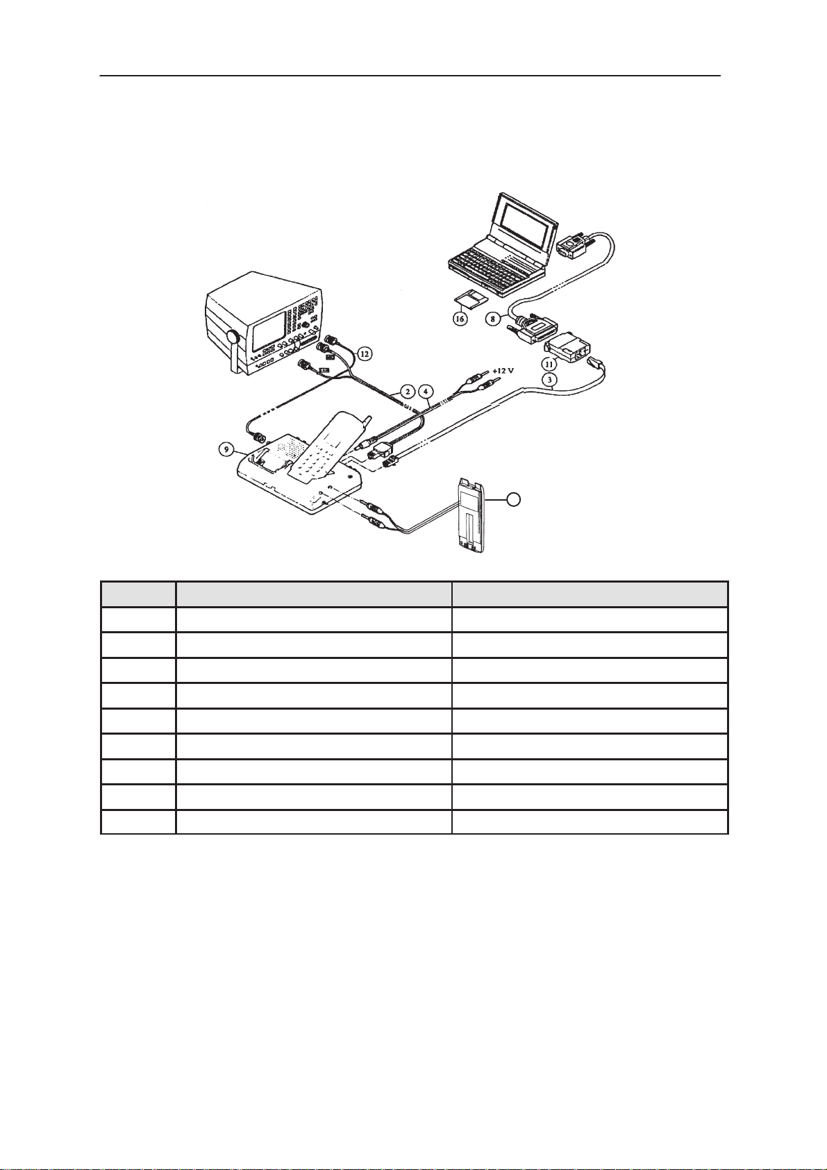
Equipment Setup for Testing a Phone with the Covers On
18
ITEM ACCESSORY PRODUCT CODE
2 Audio Cable ADS–1 0730011
3 Modular Cable XCM–1 4626131
4 Power Cable PCS–1 0730012
8 RS232 Adaptor (9–25 pin) 4626170
9 Service Box JTS–1 0770018
11 PC / M2BUS Adaptor DAU–2 0750006
12 BNC–BNC RF Cable NOT SUPPLIED
16 Service Software LSN–2K 0193718
18 Dummy Battery BTS–6 0770020
Original, 12/95
Page 7
Page 8
THA–4S
After Sales
TESLA Service Software User Guide
Technical Documentation
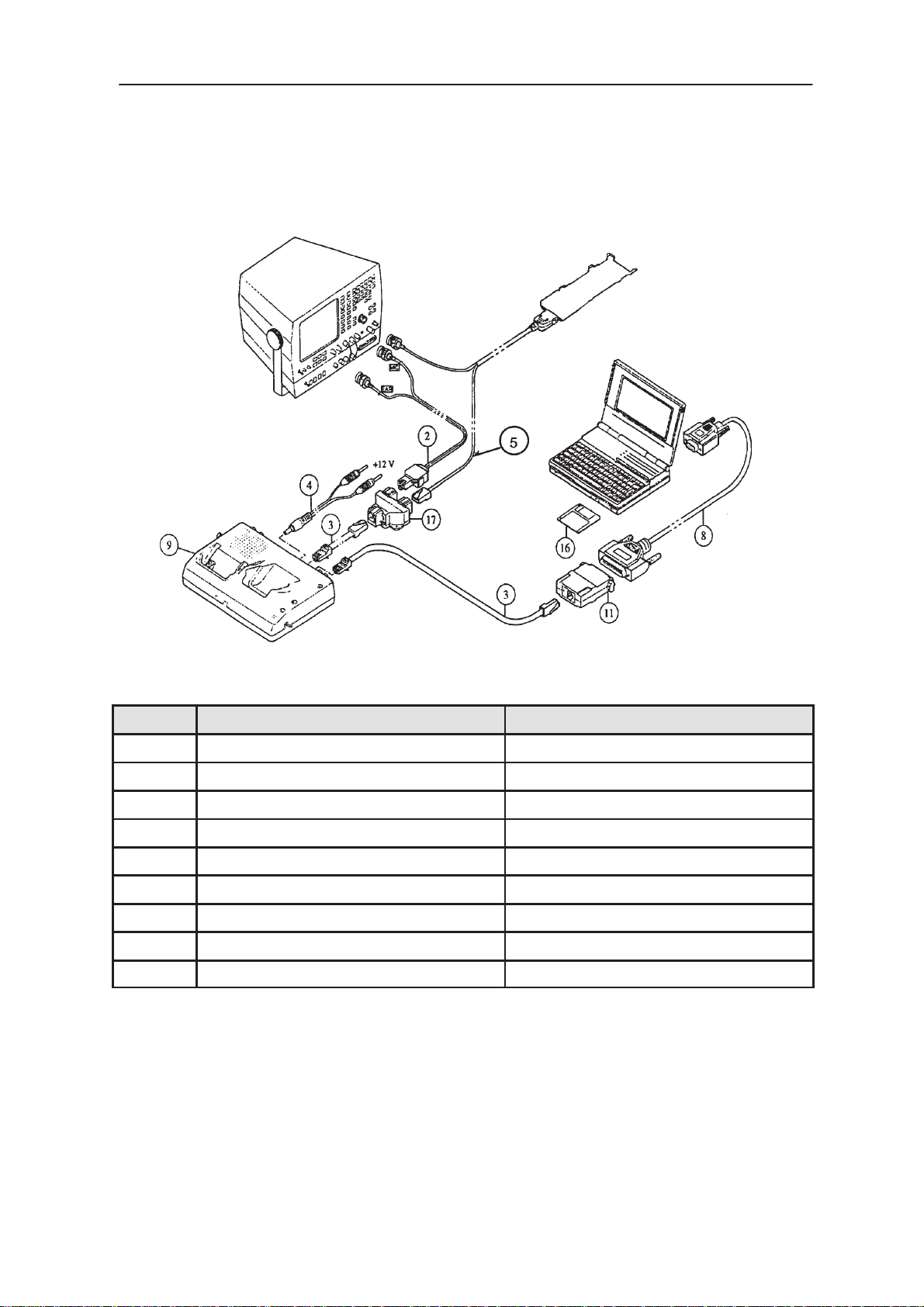
Equipment Setup for Testing a Phone with the Covers Off
ITEM ACCESSORY PRODUCT CODE
2 Audio Cable ADS–1 0730011
3 Modular Cable XCM–1 4626131
4 Power Cable PCS–1 0730012
5 Service Cable SCC–5 0770019
8 RS232 Adaptor (9–25 pin) 4626170
9 Service Box JTS–1 0770018
11 PC / M2BUS Adaptor DAU–2 0750006
16 Service Software LSN–2K 0193718
17 Modular T–connector 4626134
Page 8
Original, 12/95
Page 9
After Sales
THA–4S
Technical Documentation
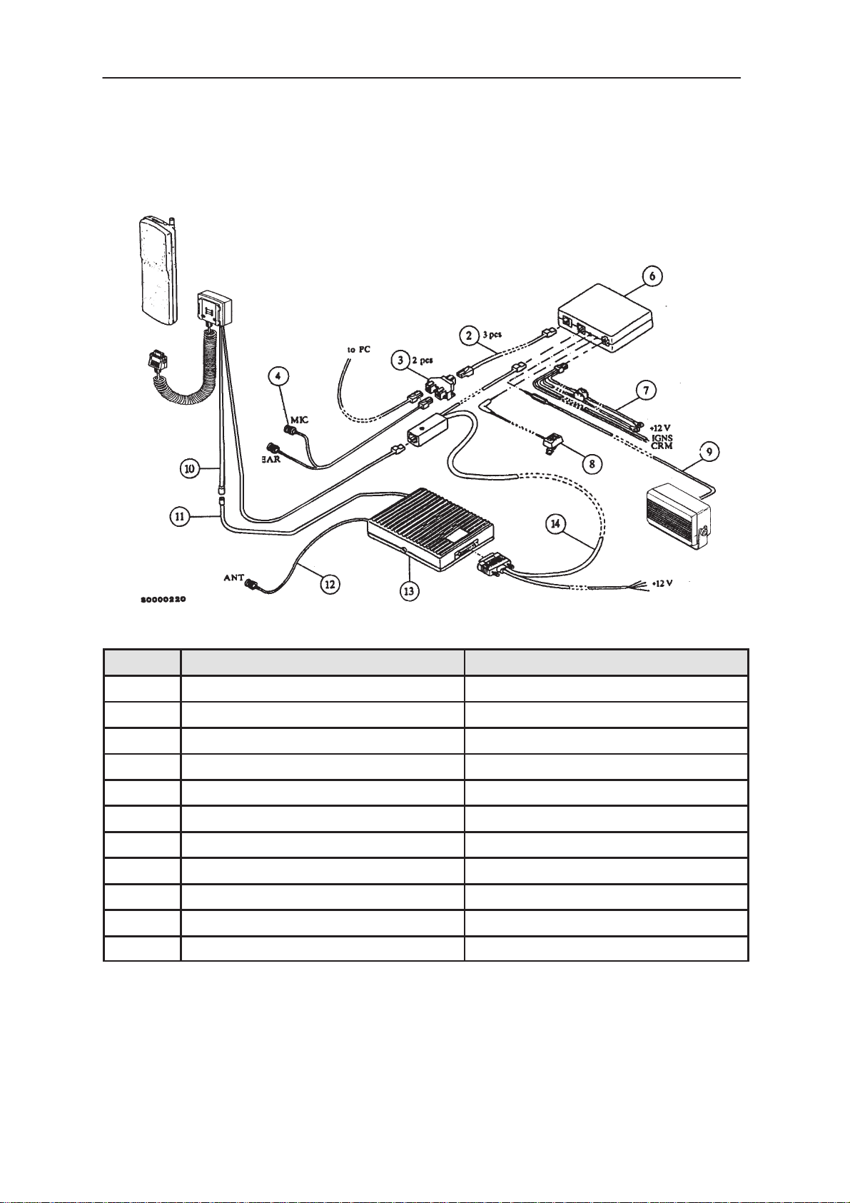
Equipment Setup for Booster Tuning
TESLA Service Software User Guide
ITEM ACCESSORY PRODUCT CODE
2 Modular Cable XCM–1 4626131
3 Modular T–connector 4626134
4 Audio Cable ADS–1 0730011
6 HF Junction Box HFJ–2 0694006
7 Power Cable PCH–4 0730009
8 HF Microphone HFM–3 0690001
9 HF Speaker HFS–6 0692006
10 Cable Junction Box JBH–1 0630008
12 Antenna Cable 9780014
13 Booster BSH–2 0500053
14 Front Mount Cable SCE–2 0730014
Original, 12/95
Page 9
Page 10

THA–4S
After Sales
TESLA Service Software User Guide
Start–up Procedure
From diskette
1.Switch the phone on; press power–on button of the handset.
2.Switch on the PC.
3.Insert the TESLA disk into drive A of your PC
4.Log into drive A:
5.Start TESLA.EXE and run TESLA
From hard disk
1.Log into drive C:
2.Start TESLA.EXE and run TESLA
Technical Documentation
type A:
< Enter >
type TESLA
<Enter >
type C:
< Enter >
type TESLA
< Enter >
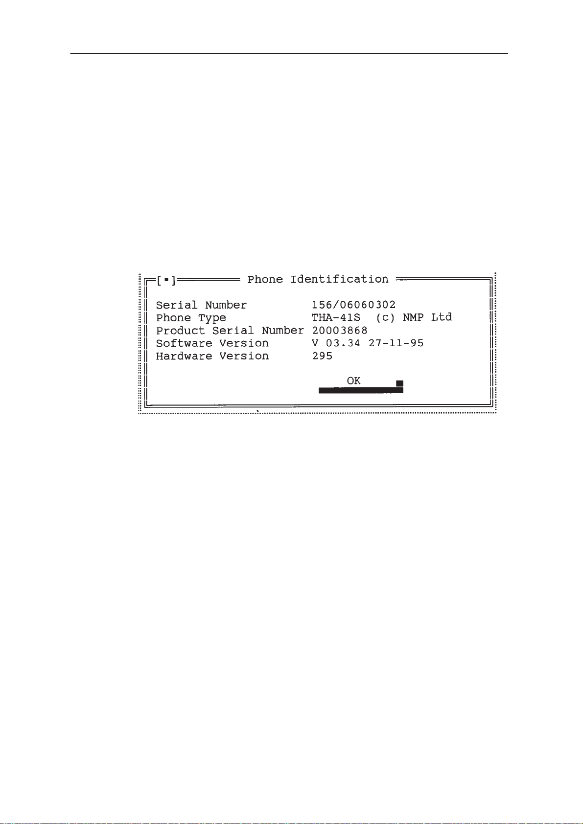
The TESLA Service Software starts by loading the configuration file. After
the configuration file has been loaded, a menu bar appears on the top line
of the display. Refer to section ” Using Menus ” for how to proceed
through the menus. A Phone Identification Window, which displays some
basic information about the connected phone, appears in the middle of the
display.
Press Enter to close the Phone Identification Window.
Page 10
Original, 12/95
Page 11

After Sales
THA–4S
Technical Documentation
TESLA Service Software Menu Structure
Open F3
Save F2
Save As
Read Phone F4
Edit
Edit NAM file
Country Data
Default Country
TuningFile Testing Dealer Help
Initialize Local Mode
PA Bias
VCTCXO
RXVCO
TX Power Level
IF Trim
Deviation
TESLA Service Software User Guide
Phone Mode Local/System F6
Quick Testing/Setup AMPS
Quick Testing/Setup NAMPS
Audio Controls
Signalling Control
RX VCO Checking
TX VCO Checking
Exit ALT +X
ADC
RSSI
First Blocked Channel
Audio
Tuning Values
TX Power High Level
ADC Readings
Display Test / Light Control
Error Codes
Subscriber (NAM) Number
SID Programming
Short Code Memory
User Data Transfer
Warranty Information
Help Index
General Help F1
Using Help
Product Information
Original, 12/95
Page 11
Page 12

THA–4S
After Sales
TESLA Service Software User Guide
Using Menus
There are three visible components to TESLA: the menu bar at the top,
the window area in the middle and the status line at the bottom of the
screen. Many menu items also offer dialogue boxes. Although there are
several different ways to make a selection in TESLA, they all access the
same commands and dialogue boxes.
The
menu bar
When a command is followed by an ellipsis (...), additional sub–menu(s)
are available, otherwise the action occurs as soon as the command is
chosen.
To choose menu commands using the keyboard proceed as follows:
Press F10 to make the menu bar active; the next characters you type
will relate to the items on the menu bar.
Use the ← → arrow keys to select the menu you wish to display and then
press Enter. As a shortcut to this step you can just select the highlighted
letter of the menu title. For example, when the menu bar is active, press
F to move to and display the File menu. At any time press Alt and the
highlighted letter ( eg
is the primary method of accessing the menu commands.
Technical Documentation
Alt
+ F ) to display the menu you want.
Use the ↑ ↓ arrow keys to select command from the menu you have
opened and press Enter. As a shortcut you can just press the
highlighted letter of the menu command.
At this stage, TESLA either carries out the command, displays a dialogue
box or displays another menu.
There are two ways to choose commands using the mouse:
Click the desired menu title to display the menu and click the desired
command.
OR
Drag from the menu title down to the menu command. Release the
mouse button on the command you want. If you change your mind,
simply drag off the menu and no command will be chosen.
TESLA offers a number of quick ways to choose menu commands. The
click–drag method for mouse users is an example. From the keyboard,
you can use a number of keyboard shortcuts ( or ’hotkeys’ ) to access the
menu bar, choose commands or work with dialogue boxes. You need to
hold down Alt while pressing the highlighted letter when moving from input
box to a group of buttons or boxes.
Page 12
Original, 12/95
Page 13
After Sales
THA–4S
Technical Documentation
Windows
Some of the actions you see and do in TESLA happens in a window. A
window is a screen area that you can open, close and move.
Most of the windows have these things in common:
a title bar
a close box
scroll bars
The following figure shows a typical window:
TESLA Service Software User Guide
The close box of a window is the box in the upper left corner. Click this
box to quickly close the window.
The title bar, the uppermost horizontal bar of a window, contains the name
of the window. You can drag the title bar to move the window around the
screen.
You can use scroll bars with a mouse to scroll the contents of a window.
Click the arrow at either end to scroll one line at a time ( keep the mouse
button pressed to scroll continuously). You can click the shaded area
either side of the scroll box to scroll one page at a time. Finally, you can
drag the scroll box to any spot on the bar to quickly move to a spot in the
window relative to the position of the scroll box. From the keyboard you
can scroll the window contents using the arrow keys.
Original, 12/95
Page 13
Page 14

THA–4S
After Sales
TESLA Service Software User Guide
Dialogue Boxes
Most of the menu commands lead to a dialogue box. Dialogue boxes
offer a convenient way to view and set multiple options. They are typically
used for making settings or performing some action where the phone
must be in a certain state and all other actions must be denied. When you
are making settings in a dialogue box you work with five basic types of
on–screen control:
action buttons
radio buttons
check boxes
input boxes
list boxes
Dialogue boxes also have similar features to windows; title bar and close
box. Below is a sample box which shows some of these features:
Technical Documentation
Page 14
This dialogue box has two standard buttons: Enter and Esc. If you choose
Enter, or the associated command (‘W rite to phone’ in this case), the choices
in the dialogue box are accepted. If you choose Esc, the dialogue box is
exited and no parameters are changed. Esc is always a keyboard shortcut to
exit the dialogue box.
Original, 12/95
Page 15

After Sales
THA–4S
Technical Documentation
If you are using a mouse, click the dialogue–box button you want. When
you are using the keyboard, press
to activate it. Press Tab to move forwards or backwards from one item to
another in a dialogue box. Each element is highlighted when it becomes
active.
Radio buttons operate in a similar manner to car–radio buttons. They are
arranged in groups, and only one radio button in a group can be selected
at any one time. To choose a radio button, click it or its text. From the
keyboard, select Alt and the highlighted letter or press Tab until the group
is highlighted, and then use the arrow keys to choose a particular radio
button. Press Tab again to leave the group with the new radio button
chosen.
Check boxes differ from radio buttons in that you can have any number of
check boxes selected at any time. When you select a check box an X
appears in it to indicate it has been selected. An empty box indicates it is
not selected. To change the status of a check box, click it or its text, press
Tab until the check box is highlighted and then press the Spacebar or
select Alt plus the highlighted letter.
TESLA Service Software User Guide
Alt
and the highlighted letter of an item
If several boxes apply to a topic, they appear as a group. In this case
tabbing moves to the group. Once the group is selected use the arrow
keys to select the item you want and then press Spacebar to check or
uncheck it.
Input boxes let you type in text. Most basic text–editing keys work in the
text box ( for example arrow keys, Home, End, Backspace, Del and Ins ).
If the contents of the input box are highlighted ( typically when you first
select it ) and you start typing in new data, the old data is erased.
A final component of some dialogue boxes is a list box, which lets you
scroll through and select from variable length lists without leaving a
dialogue box. You make a list box active by clicking it or by choosing the
highlighted letter of the list title ( or press Tab until it is highlighted ). Once
a list box is displayed, you can use the scroll box to move through the list
or press the ↑ ↓ arrow keys from the keyboard.
Original, 12/95
Page 15
Page 16

THA–4S
After Sales
TESLA Service Software User Guide
File–Selection Dialogue Box
The File–Selection Dialogue box allows you to select and open a file,
enabling you to either read data from, or write data to that file. Below is
an example of such a box:
Technical Documentation
Overview
TESLA is divided into 5 main blocks: File, Tuning, Testing, Dealer and
Help.
File is used to save all parameters to a configuration file to enable set up
as required. It is possible to change the PC settings to a configuration file
as well as the default parameters of the phone such as channel number,
transmitter on / off, audio settings etc. It is also used to edit default
settings for NAM information.
Tuning contains the functions required for tuning the phone.
Testing contains the functions required for testing the phone in Local
mode.
Dealer is used to edit all NAM and other user information. It also contains
user data transfer programs to be used in case a faulty phone should be
replaced with a new unit.
Help contains all the help information for using TESLA.
Page 16
Original, 12/95
Page 17

After Sales
THA–4S
Technical Documentation
File Menu
The file menu contains commands related to file operations. It allows you
to save and edit configuration files and also exit TESLA.
Open
The File / Open command displays a File–Selection dialogue box that allows
you to select a configuration file to open. Y ou can edit these parameters with
File / Edit command. Once the file is opened the new values take effect. The
shortcut command for this is on Function Key F3.
Save
The File / Save command saves the previously opened configuration file.
If no file has been opened, the Save As command is performed instead.
The shortcut command for this is on Function Key F2.
Save As
TESLA Service Software User Guide
The File / Save As command allows you save the configuration file under
a different name, in a different directory or on a different drive. When you
choose this command you will see the File–Selection dialogue box for
Save File As.
Read Phone
The File / Read Phone command allows you to speed up the process of
verifying that a new phone has been connected to TESLA. When selected
TESLA will search for a phone and, when found, will display the Product
Identification Window. The shortcut command for this is on Function Key
F4.
Edit
The File / Edit command opens a dialogue box for editing Testing Menu
configuration file contents. This window is illustrated over the page:
At the top of the dialogue box you can see the name of the current
configuration file. Below that are default testing / Local mode settings.
Select the value you want to change using ’hotkeys’ (
by mouse or using Tab keys and then type in the new value. Accept the
changes by pressing ‘Store and Exit’ or abandon by pressing Esc ( or click
the corresponding button ).
Alt
+ letter ), clicking
Original, 12/95
Page 17
Page 18

THA–4S
After Sales
TESLA Service Software User Guide
Technical Documentation
Page 18
Original, 12/95
Page 19

After Sales
THA–4S
Technical Documentation
Edit NAM File
The File / Edit NAM File command open’s a Window which allows the
editing of default NAM Data to be used when programming the NAM of a
phone using the Dealer / Subscriber NAM Number menu. This Window is
illustrated below and shows an example of the file that will be delivered
with TESLA.
TESLA Service Software User Guide
TESLA will come delivered with an example of a typical NAM contents for
a USA subscriber number. This menu can be added to and updated by
any user of TESLA. It is recommended to follow the example shown in the
illustration above.
Original, 12/95
Page 19
Page 20

THA–4S
After Sales
TESLA Service Software User Guide
Country Data
The File / Country Data command opens a Window which allows the
editing of the Country Data, such as International Dialling Code, National
Dialling Code etc which is associated with the Subscriber NAM Number of
a phone. This Window is illustrated below
TESLA will come delivered with a Country Data file completed with data
for the following countries:
USA
Israel
Thailand
Philippines
Venezuala
Argentina
Mexico
Technical Documentation
Page 20
The file is user editable and other countries can be added at a later date.
Original, 12/95
Page 21

After Sales
THA–4S
Technical Documentation
Default Country
The File / Default Country command opens a Window which allows the
selection of one of the country data files for use with the Dealer /
Subscriber NAM Number menu. This Window is illustrated below.
TESLA Service Software User Guide
Exit
This menu is user selectable.
The File / Exit command exits TESLA. Before exiting, a confirmation box
is displayed. Pressing Enter quits the program and Esc cancels exiting.
Original, 12/95
Page 21
Page 22

THA–4S
After Sales
TESLA Service Software User Guide
Tuning Menu
General
Almost all tuning of the phone is carried out using TESLA software. TESLA
switches the phone/system module into Locals mode, in which the phone can
be remotely controlled via the M2BUS interface.
Tuning is achieved by the TESLA software communicating with the D/A
and A/D convertors of the phone. In some instances, the phone
processor will also calculate the required correction parameter.
The calibration data of the phone resides on the EEPROM. The contents
of the EEPROM can be read by the TESLA program and saved as a file.
This is useful when there is a need to retain this information ie. if you need
to replace the EEPROM during the repair process. The program also
enables writing of the factory preset calibration data to the EEPROM, after
which, the whole tuning process should be repeated.
Technical Documentation
If a repair has been carried out on the RF section of a system module
then the appropriate tunings should be performed as described in the
following section using the on–screen help menus as a guide.
CAUTION:
During tuning:
take care not to damage sensitive measuring instruments when
excessive RF power levels are present
perform all tuning steps in the order described
never try to mask a fault by tuning it out
Tuning Menu
This menu contains the commands required for tuning the phone.
Selecting the Tuning menu opens a sub–menu from where the desired
Tuning parameters can be selected. After you select a tuning parameter
from the sub–menu, a tuning dialogue box will be opened and all
necessary settings for the phone will be done automatically.
PA Bias Alignment
Page 22
THIS ALIGNMENT IS ONLY NEEDED FOR THA–4 SERIES PHONES.
This command allows you to tune the two stages of the TX power
amplifier separately to achieve maximum efficiency.
Original, 12/95
Page 23

After Sales
THA–4S
Technical Documentation
Tuning Procedure
1.Select Tuning / PA Bias
2.The PA Bias Calibration procedure is as follows:
a) Enter the phone current, as measured on a meter, into the Supply
Current Text Box and then select Next Stage.
b) Follow the on–screen menu instructions to set PA Driver Bias Value
and select Next Stage. Repeat this process for PA O/P Bias Value.
c) Enter the new value to EEPROM by pressing ENTER on the
keyboard or clicking on the corresponding button using the mouse.
VCTCXO Alignment
This command is used to tune the VCTCXO frequency of the phone. This
command will tune the phone to channel 380 and activate the transmitter.
Use an accurate frequency counter when measuring the resultant output.
Please note that the VCTCXO should only be aligned using TESLA. No
attempt should be made to physically tune the device using the trimming
capacitor.
TESLA Service Software User Guide
NOTE :– The target value for THA–4 Series phones is 14.85MHz
whilst for THA–4S Series phones it is 14.4MHz. The on
screen information reminds you of the target value.
Tuning Procedure
1.Select Tuning / VCTCXO Tuning
2.Adjust Tx carrier frequency (F
target value
3.Enter the new value to EEPROM by selecting Store and Exit.
RXVCO Alignment
THIS ALIGNMENT IS ONLY NEEDED FOR THA–4S SERIES PHONES.
This command allows you to adjust the RX VCO to within the optimum
lock range. This is an automatic alignment with no requirement for
external test equipment. Once the Automatic Test has been performed the
resultant DAC value radio button will be highlighted and Test Result will
read OK.
Tuning Procedure
1.Select Tuning / RX VCO
) to within +/– 50Hz of the
0
2.Select Automatic Test.
3.Enter the new value to EEPROM by selecting Store and Exit.
Original, 12/95
Page 23
Page 24

THA–4S
After Sales
TESLA Service Software User Guide
TX Power Level Alignment
This command is used to tune the phone’s TX power levels. When
selected, the transmitter will be switched on at Power Level 0 on Channel
380.
Tuning Procedure
1.Connect a power meter to the phone’s external antenna
connector
2.Select Tuning / TX Power Level
3.The Channel Number can be changed using Backspace and
Return keying commands. After Return, the cursor will return
to the last power level selected
4.To tune a Power Level, select the level you wish to tune from
the list. The target value will appear to the left of the cursor.
Use the Coarse and Fine commands until the target value is
reached.
Technical Documentation
5.Enter the new value to EEPROM using Enter New Value
6.Follow this procedure for all the Power Levels
IF Trim DAC Alignment
THIS ALIGNMENT IS ONLY NEEDED FOR THA–4 SERIES PHONES.
With this command you can check that the RX IF Frequency is tuned to
give optimum RSSI. This is an automatic process using an 8–bit DAC.
Tuning Procedure
1.Select Tuning / IF Trim Alignment
2.Set RF input signal to –93dBm on the Channel Number
indicated on the PC screen
3.Select Automatic Tuning. The RSSI is measured for each of
the 8 DAC levels, with the optimum level indicated when the
process is completed.
4.Select Re–read RSSI to check this highest level
5.Enter the new value to EEPROM by pressing Enter on the
keyboard or clicking on the corresponding button using the
mouse.
Page 24
Original, 12/95
Page 25

After Sales
THA–4S
Technical Documentation
Deviation Alignment
A number of deviation tunings are grouped together in this command.
They are, however, still tuned independently of each other.
Tuning Procedure
1.Select Tuning / Deviation
2.Select Sig Tone to move cursor and show the relevant
on–screen information for that particular tuning parameter
3.Use the Coarse and Fine commands until the target value is
reached
4.Repeat for Nominal and Maximum Deviation tunings
5.Enter the new value to EEPROM by selecting Store and Exit.
ADC Alignment
With this tuning, the Battery Reference value and Reference Charge
voltage value are both set using an accurate 6V power supply, provided
by Service Interface Box JTS–1. These tunings should not be attempted
while the phone covers are removed, as the voltage used to power the
phone is too inaccurate when not using the Dummy Battery Pack, BTS–6.
TESLA Service Software User Guide
Tuning Procedure
1.Select Tuning / ADC Calibration
2.For VBATSW, the program displays the EEPROM value
expected and the 6V A / D reading actually present on the
VBAT line. It compares the two and the difference is the value
stored to EEPROM.
3.For CHRGMON the program reads the EEPROM value
expected and the 6V A / D reading actually present on the VC
line. It compares the two and the difference is the value stored
to EEPROM.
4.Enter the new value to EEPROM by selecting Store and Exit.
Original, 12/95
Page 25
Page 26

THA–4S
After Sales
TESLA Service Software User Guide
RSSI Reference Alignment
A different window is displayed depending on whether a THA–4 or
THA–4S series phone is connected. The appropriate window is
displayed automatically with no manual selection required from the
user.
FOR THA–4 SERIES PHONES this consists of tuning the noise floor
reference value for the RSSI meter. This is carried out with no input signal
present.
Tuning Procedure
1.Select Tuning / RSSI Reference
2.Disconnect the RX signal from the phone’s external antenna
connector and press Return
3.The program displays the reference value stored in the
phone together with the value read from the A / D convertor.
The A / D value can be re–read by pressing the spacebar.
Technical Documentation
4.Enter the new value to EEPROM by selecting Store and Exit.
FOR THA–4S SERIES PHONES this consists of aligning the RSSI
reading at 7 different input signal levels between –75 dBm and –105 dBm.
The default channel for this alignment is channel 380. If desired this can
be changed using the File / Edit Menu.
Tuning Procedure
1.Select Tuning / RSSI Reference.
2.Set RF input level to –75 dBm at Chnannel 380.
3.Select the Space Bar to measure the RSSI reading.
4.Set RF input level to –80 dBm and repeat Step 3.
5.Complete the above proces for all 7 levels.
6.Enter the new values to EEPROM by selecting Store and
Exit.
Page 26
Original, 12/95
Page 27

After Sales
THA–4S
Technical Documentation
First Blocked Channel
The harmonic components of the modem crystal can decrease the
sensitivity of the receiver on some channels. To prevent this blocking
effect, the oscillator frequency is measured so that the frequency can be
shifted slightly at those channels which could be blocked.
Tuning Procedure
1.Select Tuning / First Blocked Channel
2.Connect a Frequency Counter to pin 7 of N403 ( THA–4
phones ) or D100 ( THA–4S phones ) on the System Module.
3.Write the measured frequency to the Text Editing Box.
4.Enter the new value to EEPROM by selecting Store and Exit.
Audio Settings
This menu allows you to set up the NANTIC registers for the internal and
external microphone and loudspeaker signals.
TESLA Service Software User Guide
Tuning Values
With this command you can save the Tuning Data from the EEPROM to a
file. You can also write either previously saved data or factory default
values from a file to a phone’s EEPROM. This is useful if the EEPROM
device has had to be replaced during the repair procedure.
TX Power High Level
THIS ALIGNMENT IS ONLY NEEDED FOR THA–4S SERIES
PHONES.To compensate for the characteristics of the chosen PA module
it is necessary to align Power Level 0 at 8 points across the TX band,
starting at Channel 19 and finishing at Channel 747. At each of these
Channels is an appropriate Power Factor i.e. Power Factor 0 at Channel
19, Power Factor 1 at Channel 123 etc.
NOTE This Power Factor is not the Power Level to be aligned to. The
Power Level to be aligned to is always Power Level 0 i.e. target
value is always 28dBm at each channel.
1.Connect a power meter to the phone’s external antenna
connector
2.Select Tuning / TX High Power Level.
3.Select Power Factor 0 from the list. The target value is 28
dBm. Use the Coarse and Fine commands until the target
value is reached.
4.Enter the new value to EEPROM using Enter New Value.
5.Follow this procedure for all the Power Factors.
Original, 12/95
Page 27
Page 28

THA–4S
After Sales
TESLA Service Software User Guide
Testing Menu
The Testing Menu allows the Service Technician to switch a phone to
Local mode in order to attempt to simulate a reported fault or configure a
phone to test a certain parameter. It allows the technician complete
control over internal and external audio, and the RF settings.
When Testing is selected, the phone is placed into Service mode
automatically. This is known as Local mode. Unless the user changes
this configuration, using File, the phone receiver is tuned to Channel 380;
the Transmitter synthesiser is also tuned to Channel 380 but with the
power amplifier switched off.
Phone Mode – Local / System
This allows you to change from Local Mode to normal System Mode and
back to Local Mode. Function Key F6 also operates this feature.
Quick Testing / Setup AMPS
Technical Documentation
This command opens a Window allowing the user full control over the
channel the phone is tuned to; the transmit power state; and access to
some simple audio routing and signal switching.
Audio Controls
This command allows you to test all possible audio paths in and out of the
audio processing device including XMIC, XEAR and DTMF.
Signalling Control
This command allows the setting of the following signalling parameters.
The * symbol in each column indicates the phone’s present state.
Supervisory Tone
SAT 0 5970 Hz
SAT 1 6000 Hz
SAT 2 6030 Hz
SAT Off
Sig Tone
Page 28
ST On
ST Off
Original, 12/95
Page 29

After Sales
THA–4S
Technical Documentation
Data Output
Wide Band Data On
Wide Band Data Off
State
Mute
Mic
Ext Mic
DTMF
Quick Testing / Setup NAMPS
THIS MENU IS ONLY ACCESSIBLE WITH THA–4S SERIES PHONES.
In addition to all of the features available in Quick Testing / Setup AMPS
this menu also allows the selection of the Narrow Band Channels used in
NAMPS.
TESLA Service Software User Guide
Audio Testing
This command will allow the checking of the audio signals through the
various paths of the NANTIC audio device.
Signalling Control
This command allows full control over the following Signalling parameters
of the phone:
Supervisory Tone, Signalling Tone, Data Output, TX Power State and
selection of microphone path.
RX VCO Checking
This command will check that the RX VCO synthesiser will lock across the
required bandwidth. This is only a check facility; there is no parametrical
tuning involved. You can select Scan Band for complete bandwidth
analysis or Frequency Sweep for Cellular Bandwidth analysis.
TX VCO Checking
THIS MENU IS ONLY ACCESSIBLE WITH THA–4 SERIES PHONES.
This command will check that the TX VCO synthesiser will lock across the
required bandwidth. This is only a check facility; there is no parametrical
tuning involved. You can select Scan Band for complete bandwidth
analysis or Frequency Sweep for Cellular Bandwidth analysis.
Original, 12/95
Page 29
Page 30

THA–4S
After Sales
TESLA Service Software User Guide
ADC Reading
This displays a table showing the following readings of the A / D
convertors.
0 VBATSW Battery voltage
1 CHRGMON Charge voltage
2 RSSI Received Signal Strength
3 TXI Transmit power monitor
4 BTEMP Battery temperature
5 HOOK Hook line
6 BSI Battery size indication
7 HFCON Handsfree control
Technical Documentation
Display Test and Light Control
This enables checking of the operation of the display segments and the
phone backlighting.
Display Test
Clear Display
Fill pattern 1 switches on all icons and fills alphanumeric area with a
pattern
Fill with pattern 2 switches on all icons and fills alphanumeric area with a
different pattern
Fill with pattern 3 switches on all icons and fills alphanumeric area with a
different pattern
Lights
On switches on all backlighting
Off switches off all backlighting
Page 30
Original, 12/95
Page 31

After Sales
THA–4S
Technical Documentation
Reading Error Codes
This command can give one of the following error codes.
1 Error in EEPROM id field
2 Error in EEPROM RF tuning parameters
3 Error in EEPROM audio tuning parameters
4 Error in EEPROM device / charge tuning parameters
5 Error in checking the serial number
7 Error in the modem circuit
or ’No Error Detected’
Dealer
Selecting Dealer will bring up a sub–menu as shown below:
TESLA Service Software User Guide
Subscriber ( NAM ) number
Short code memory
User menu settings
User data transfer
Original, 12/95
Page 31
Page 32

THA–4S
After Sales
TESLA Service Software User Guide
Subscriber ( NAM ) Number
This can be used to program all the Subscriber Data and Common NAM
Data information into a phone. This can also be programmed through the
phone’s keypad. A customisation feature is also available through File
menu. This allows the user to set up common system data / default
settings for any cellular operator and then recall them in this menu. It is
primarily aimed as a time saving feature for dealers.
CAUTION: If you wish to only view and not change the NAM
information, press Esc to exit the screen.
Either NAM in the phone can be read from / written to by selecting either
1or 2. When a selection is made all the NAM information displayed on the
PC is updated. Basic information displayed next to 1 and 2 is operator
name (if the phone has been programmed using the customisation
feature) and Subscriber Number.
Technical Documentation
Page 32
In the example Figure above ( taken from a THA–4 Series Phone ), this is
ESN Displayed 156/02062973
NAM
( * ) 1 – Customised – 1111111111
( ) 2
From this example it can be seen that NAM 1 has been programmed.
The ESN of the phone is also clearly displayed.
Dealers are strongly advised to use the customisation feature. For any
operator they could store, as the default setting, the following parameters:
Original, 12/95
Page 33

After Sales
THA–4S
Technical Documentation
Country – this information should contain the international prefix,
country code and national prefix.
Home SID – this number is used to define the primary traffic area of the
phone. The number contains the country code, system bit information
and the area code.
Access Q – this is used to define the method of sending the phone
identification data (1 = country code in use; 0 = no country code in use).
Local Cmd – this is used to determine if Local Mode Mesaages are
accepted.
Paging Ch – this number is used to identify the primary traffic channel
of the phone.
ACCOLC – this number is used to identify which overload class the
phone belongs to.
Group – this is used to determine which group the phone is opearting
in.
TESLA Service Software User Guide
You are also able to store:
Language –With THA–4 Series Phones 3 languages can be selected
(English, French or Spanish). With THA–4S Series Phones 2
languages can be selected ( English or Spanish ).
Emergency 9 – 3 different emergency numbers can be defined. The
principal emergency number programmed should be the emergency
number applicable to the user’s primary location.
The process for programming a NAM with this method is as follows:
1.Select NAM 1 or 2.
2.Select Default – scroll through the available defaults using
the arrow keys until you find the desired default. All the default
information will be displayed on the PC screen
3.Select Number and program the new subscriber number
using the normal text editing keys
4.Select Wake up and program the new Wake up message
using the normal text editing keys. To help with the message
alignment, the phone’s display will constantly be updated
during this process
5.Select Security and program the new security code using the
normal text editing keys
6.Select Enter to save to EEPROM.
Alternatively, the user is able to program each individual parameter if they
choose not to use the customisation feature.
Original, 12/95
Page 33
Page 34

THA–4S
After Sales
TESLA Service Software User Guide
SID Programming
Selecting Dealer / SID Programming allows the user to set up System
Area ID’s as either Friendly or Unfriendly. When Roaming the phone is
then able to select the system which is most desirable for the phone to
operate on. Each NAM can have up to 31 SID’s programmed into it’s
memory. An example of the SID Programming sub–menu is shown below.
Technical Documentation
Place the cursor over the desired SID location and press Enter or click on
the cursor with the mouse. Select either Friendly or Unfriendly. Change to
the number editing box field with the TAB key or clicking with a mouse.
Now enter the numerical value of the SID.When this is complete you are
able to accept the new values and return to the full SID dialogue box by
pressing ENTER or by clicking the corresponding button. ESC will cancel
the operation.
You are able to perform the following actions by selecting the
corresponding button:
File Load ( Alt + L ) – reads SID data from a file. You can select a file to
be loaded from the File selection dialogue box.
File Save ( Alt + S ) – writes SID data to a file. You can select the file to
write to from the File selection dialogue box.
Read Phone ( Alt + R ) – reads SID data from the phone and updates it
to the display.
Write Phone ( Alt + W ) – writes SID data to the phone. Before the data
is written to the phone the user is asked to confirm the new data.
Esc–Close – closes the SID programming dialogue box. Click the
button or press the ESC key.
Page 34
Original, 12/95
Page 35

After Sales
THA–4S
Technical Documentation
Short Code Memory
Selecting Dealer / Short Code Memory opens the short code memory
dialogue box. In this box you can view and edit all 99 memory locations of
the phone. You can also store the information to a file and read
information from a file. It is possible to transfer the SCM Location data
from one THA–4 Series Phone to a THA–4S Series Phone and vice versa
but the usage of the SCM Locations differs between the two series of
phones. In the THA–4 Series SCM Locations 1–99 are used to store
numbers. In the THA–4S Series only SCM Locations 1–69 and 90–98 are
used to store numbers whilst SCM Locations 70–89 are used for Digital
Message Service usage. When attempting to carry out transfer of data
between THA–4 and THA–4S Series phones a series of information dialog
boxes will be displayed giving information about the impending transfer.
The SCM editing dialogue box is shown below:
TESLA Service Software User Guide
Original, 12/95
Page 35
Page 36

THA–4S
After Sales
TESLA Service Software User Guide
Place the cursor over the desired SCM location and press Enter or click
on the cursor with the mouse. In the editing dialogue box, edit or type in a
new name and number. You can change the field with the TAB key or
clicking with a mouse. When this is complete you are able to accept the
new values and return to the full SCM dialogue box by pressing ENTER or
by clicking the corresponding button. ESC will cancel the operation.
You are able to perform the following actions by selecting the
corresponding button:
File Load ( Alt + L ) – reads SCM data from a file. You can select a file
to be loaded from the File selection dialogue box.
File Save ( Alt + S ) – writes SCM data to a file. You can select the file
to write to from the File selection dialogue box.
Read Phone ( Alt + R ) – reads SCM data from the phone and updates
it to the display.
Write Phone ( Alt + W ) – writes SCM data to the phone. Before the
data is written to the phone the user is asked to confirm the new data.
Technical Documentation
Esc–Close – closes the SCM programming dialogue box. Click the
button or press the ESC key.
Page 36
Original, 12/95
Page 37

After Sales
THA–4S
Technical Documentation
User Data Transfer
Selecting Dealer / User Data Transfer allows all the User data (excluding
the ESN) to be transferred from one phone and programmed into another
phone. Also in this dialogue box you are able to reset all the following
parameters to the factory default values:
Subscriber (NAM) numbers
Short Code Memory
SID Screening Table
User Menu Settings
An example of the user data transfer dialogue box is shown
below.
TESLA Service Software User Guide
Select with check boxes which information you wish to transfer or reset to
factory values.
In the dialogue box the following buttons are available:
File Load ( Alt + L ) – reads user data from a file. You can select a file
to be loaded from the File selection dialogue box. Only items that were
checked can be read back.
File Save ( Alt + S ) – writes user data to a file. You can select the file
to write to from the File selection dialogue box. Only items that were
checked can be stored to the file.
Read Phone ( Alt + R ) – reads user data items that are checked from
the phone.
Write Phone ( Alt + W ) – writes user data to the phone. Before writing
the user is asked to confirm the writing.
Reset ( Alt + T ) – Resets the checked items to the original factory
values.
Esc–Close – closes the user transfer dialogue box. Click the button or
press the ESC key.
Original, 12/95
Page 37
Page 38

THA–4S
After Sales
TESLA Service Software User Guide
Warranty Information
THIS MENU IS AVAILABLE ONLY WITH THA–4S SERIES PHONES.
Selecting Dealer / Warranty Information allows user to view the status of
the Warranty Information TESLA allows the facility to transfer User Data
and Warranty Information between phones to support an Over The
Counter Exchange Program. Data from a THA–4 Series phone can be
programmed to a THA–4S Series phone but not vice versa.
Original ESN – This is the ESN of the phone connected.
Warranty ESN – If this phone has had data transferred from another
phone then a copy of the ESN of that other phone is stored to this
location in EEPROM. It is never transmitted.
Manufacturing Month – Stored here is the month that the phone was
manufactured.
Repair Month – If a phone is returned for repair then the repair month
can be stored here.
Technical Documentation
Purchase Month – The month the phone was purchased in can be
entered here.
Read Phone ( Alt + R ) – reads Warranty Information from the phone.
Write Phone ( Alt + W ) – writes Warranty Information to the phone.
Before writing the user is asked to confirm the writing.
Reset ( Alt + T ) – Resets the checked items to the original factory
values. This is important as if a phone is returned for repair which has
had its data transferred to another phone it will be returned as a
defective phone.
Esc–Close – closes the user transfer dialogue box. Click the button or
press the ESC key.
Page 38
Original, 12/95
Page 39

After Sales
THA–4S
Technical Documentation
Help Menu
The Help menu gives you access to the online help facility in a special
window.
General Help
Choose Help/General Help to obtain general help information about the
service TESLA.
Using Help
Choose Help/Using Help to obtain information on how to use the help
facilities.
Product Information
Choose Help / Product Information to display information about the
Version Number and copyright of the TESLA Service Software.
TESLA Service Software User Guide
Original, 12/95
Page 39
Page 40

THA–4S
After Sales
TESLA Service Software User Guide
[This page intentionally left blank]
Technical Documentation
Page 40
Original, 12/95
Page 41

After Sales
Technical Documentation
General 5. . . . . . . . . . . . . . . . . . . . . . . . . . . . . . . . . . . . . . . . . . . . . . . . . . . . . . . . .
Required Servicing Equipment 5. . . . . . . . . . . . . . . . . . . . . . . . . . . . . . . . . . . . .
Mechanical Connections 6. . . . . . . . . . . . . . . . . . . . . . . . . . . . . . . . . . . . . . . . . .
Equipment Setup for Testing a Phone with the Covers On 7. . . . . . . . . .
Equipment Setup for Testing a Phone with the Covers Off 8. . . . . . . . . .
Equipment Setup for Booster Tuning 9. . . . . . . . . . . . . . . . . . . . . . . . . . . . .
Start–up Procedure 10. . . . . . . . . . . . . . . . . . . . . . . . . . . . . . . . . . . . . . . . . . . . . . .
TESLA Service Software Menu Structure 11. . . . . . . . . . . . . . . . . . . . . . . . . . . .
Using Menus 12. . . . . . . . . . . . . . . . . . . . . . . . . . . . . . . . . . . . . . . . . . . . . . . . . . . .
Windows 13. . . . . . . . . . . . . . . . . . . . . . . . . . . . . . . . . . . . . . . . . . . . . . . . . . . . . . . .
Dialogue Boxes 14. . . . . . . . . . . . . . . . . . . . . . . . . . . . . . . . . . . . . . . . . . . . . . . . . .
THA–4
File–Selection Dialogue Box 16. . . . . . . . . . . . . . . . . . . . . . . . . . . . . . . . . . . . . . .
Overview 16. . . . . . . . . . . . . . . . . . . . . . . . . . . . . . . . . . . . . . . . . . . . . . . . . . . . . . . .
File Menu 17. . . . . . . . . . . . . . . . . . . . . . . . . . . . . . . . . . . . . . . . . . . . . . . . . . . . . . .
Open 17. . . . . . . . . . . . . . . . . . . . . . . . . . . . . . . . . . . . . . . . . . . . . . . . . . . . . . . .
Save 17. . . . . . . . . . . . . . . . . . . . . . . . . . . . . . . . . . . . . . . . . . . . . . . . . . . . . . . .
Save As 17. . . . . . . . . . . . . . . . . . . . . . . . . . . . . . . . . . . . . . . . . . . . . . . . . . . . . .
Read Phone 17. . . . . . . . . . . . . . . . . . . . . . . . . . . . . . . . . . . . . . . . . . . . . . . . . .
Edit 17. . . . . . . . . . . . . . . . . . . . . . . . . . . . . . . . . . . . . . . . . . . . . . . . . . . . . . . . . .
Edit NAM File 19. . . . . . . . . . . . . . . . . . . . . . . . . . . . . . . . . . . . . . . . . . . . . . . . .
Country Data 20. . . . . . . . . . . . . . . . . . . . . . . . . . . . . . . . . . . . . . . . . . . . . . . . .
Default Country 21. . . . . . . . . . . . . . . . . . . . . . . . . . . . . . . . . . . . . . . . . . . . . . .
Exit 21. . . . . . . . . . . . . . . . . . . . . . . . . . . . . . . . . . . . . . . . . . . . . . . . . . . . . . . . . .
Tuning Menu 22. . . . . . . . . . . . . . . . . . . . . . . . . . . . . . . . . . . . . . . . . . . . . . . . . . . .
General 22. . . . . . . . . . . . . . . . . . . . . . . . . . . . . . . . . . . . . . . . . . . . . . . . . . . . . .
Tuning Menu 22. . . . . . . . . . . . . . . . . . . . . . . . . . . . . . . . . . . . . . . . . . . . . . . . .
PA Bias Alignment 22. . . . . . . . . . . . . . . . . . . . . . . . . . . . . . . . . . . . . . . . . . . . .
18. . . . . . . . . . . . . . . . . . . . . . . . . . . . . . . . . . . . . . . . . . . . . . . . . . . . . . . . . . . . . .
VCTCXO Alignment 23. . . . . . . . . . . . . . . . . . . . . . . . . . . . . . . . . . . . . . . . . . .
RXVCO Alignment 23. . . . . . . . . . . . . . . . . . . . . . . . . . . . . . . . . . . . . . . . . . . .
TX Power Level Alignment 24. . . . . . . . . . . . . . . . . . . . . . . . . . . . . . . . . . . . .
IF Trim DAC Alignment 24. . . . . . . . . . . . . . . . . . . . . . . . . . . . . . . . . . . . . . . .
Deviation Alignment 25. . . . . . . . . . . . . . . . . . . . . . . . . . . . . . . . . . . . . . . . . . .
ADC Alignment 25. . . . . . . . . . . . . . . . . . . . . . . . . . . . . . . . . . . . . . . . . . . . . . .
RSSI Reference Alignment 26. . . . . . . . . . . . . . . . . . . . . . . . . . . . . . . . . . . . .
4
First Blocked Channel 27. . . . . . . . . . . . . . . . . . . . . . . . . . . . . . . . . . . . . . . . .
Original 05/95
Page 42

After Sales
Technical Documentation
Audio Settings 27. . . . . . . . . . . . . . . . . . . . . . . . . . . . . . . . . . . . . . . . . . . . . . . .
Tuning Values 27. . . . . . . . . . . . . . . . . . . . . . . . . . . . . . . . . . . . . . . . . . . . . . . .
TX Power High Level 27. . . . . . . . . . . . . . . . . . . . . . . . . . . . . . . . . . . . . . . . . .
Testing Menu 28. . . . . . . . . . . . . . . . . . . . . . . . . . . . . . . . . . . . . . . . . . . . . . . . . . . .
Phone Mode – Local / System 28. . . . . . . . . . . . . . . . . . . . . . . . . . . . . . . . . .
Quick Testing / Setup AMPS 28. . . . . . . . . . . . . . . . . . . . . . . . . . . . . . . . . . . .
Quick Testing / Setup NAMPS 29. . . . . . . . . . . . . . . . . . . . . . . . . . . . . . . . . .
Audio Testing 29. . . . . . . . . . . . . . . . . . . . . . . . . . . . . . . . . . . . . . . . . . . . . . . . .
Signalling Control 29. . . . . . . . . . . . . . . . . . . . . . . . . . . . . . . . . . . . . . . . . . . . .
RX VCO Checking 29. . . . . . . . . . . . . . . . . . . . . . . . . . . . . . . . . . . . . . . . . . . .
TX VCO Checking 29. . . . . . . . . . . . . . . . . . . . . . . . . . . . . . . . . . . . . . . . . . . . .
ADC Reading 30. . . . . . . . . . . . . . . . . . . . . . . . . . . . . . . . . . . . . . . . . . . . . . . . .
Display Test and Light Control 30. . . . . . . . . . . . . . . . . . . . . . . . . . . . . . . . . .
Reading Error Codes 31. . . . . . . . . . . . . . . . . . . . . . . . . . . . . . . . . . . . . . . . . .
Dealer 31. . . . . . . . . . . . . . . . . . . . . . . . . . . . . . . . . . . . . . . . . . . . . . . . . . . . . . .
SID Programming 34. . . . . . . . . . . . . . . . . . . . . . . . . . . . . . . . . . . . . . . . . . . . .
Short Code Memory 35. . . . . . . . . . . . . . . . . . . . . . . . . . . . . . . . . . . . . . . . . . .
User Data Transfer 37. . . . . . . . . . . . . . . . . . . . . . . . . . . . . . . . . . . . . . . . . . . .
Warranty Information 38. . . . . . . . . . . . . . . . . . . . . . . . . . . . . . . . . . . . . . . . . .
Help Menu 39. . . . . . . . . . . . . . . . . . . . . . . . . . . . . . . . . . . . . . . . . . . . . . . . . . .
4
Original, 03/94Page 42
 Loading...