

Page 1

After Sales
THA–4S
Technical Documentation
THA– 4S SERIES
CORE TRANSCEIVER
Core Transceiver
Original, 09/95
NMP Part No. 0275168
Page 2

After Sales Technical Documentation
THA–4S Series Transceiver
CONTENTS
Amendment Record Sheet
Chapter 1 Foreword
Chapter 2 Performance Specifications
Chapter 3 Transceiver Overview
Chapter 4 System Module
Chapter 5 Display Module
Original, 12/95
Page 3

After Sales Technical Documentation
THA–4S Series Transceiver
AMENDMENT RECORD SHEET
Amendment
Number
Date Inserted By Comments
Original, 12/95
Page 4

After Sales Technical Documentation
THA – 4S Series Transceiver
Chapter 1
FOREWORD
Original, 12/95
Page 5

THA–4S
After Sales
Foreword
Technical Documentation
CHAPTER 1 – FOREWORD
CONTENTS
Page No
Introduction 1–3. . . . . . . . . . . . . . . . . . . . . . . . . . . . . . . . . . . . . . . . . . . . . . . . . . . . . . . . . . . .
Service Manual Structure 1–3. . . . . . . . . . . . . . . . . . . . . . . . . . . . . . . . . . . . . . . . . .
Company Policy 1–4. . . . . . . . . . . . . . . . . . . . . . . . . . . . . . . . . . . . . . . . . . . . . . . . . .
Warnings and Cautions 1–4. . . . . . . . . . . . . . . . . . . . . . . . . . . . . . . . . . . . . . . . . . . . . . . . .
Page 1–2
Original, 12/95
Page 6

After Sales
THA–4S
Technical Documentation
Introduction
Service Manual Structure
The service manual is structured as a series of stand–alone booklets. The
’core’ service manual consists of the following:
THA–4S Series Transceiver booklet
Chapter 1: Foreword
Chapter 2: Performance Specifications
Chapter 3: Transceiver Overview
Chapter 4: System Module
Chapter 5: Display Module
Appendix to the Transceiver booklet
THA–41S comprising:
Chapter 1: Foreword
Foreword
comprising
covering a specific variant (ie
Chapter 2: Transceiver variant
Chapter 3: Quick Guide
TESLA Service Software
The accessory booklets comprise an overview; separate booklets covering
those accessories deemed to be serviceable; and a booklet covering the
remaining (non–serviceable) accessories.
Accessory Overview
LCH–2 Cigarette Lighter Charger
HFJ–2 Handsfree Junction Box
JBH–1 Cable Junction Box
BSH–2 Booster Kit
CHH–6 Desktop Charger
CHH–7 Handsfree Desktop Charger
PHF–2 Compact Handsfree Unit
Non–serviceable Accessories
Other booklets available are:
CARK14 Installation Guide
CARK15 Installation Guide
Original, 12/95
Page 1–3
Page 7

THA–4S
After Sales
Foreword
Company Policy
Our policy is of continuous development; details of all technical
modifications will be included with service bulletins.
While every endeavour has been made to ensure the accuracy of this
document, some errors may exist. If any errors are found by the reader,
NOKIA MOBILE PHONES Ltd should be notified in writing.
Please state:
Title of the Document + Issue Number/Date of publication
Latest Amendment Number (if applicable)
Page(s) and/or Figure(s) in error
Please send to: Nokia Mobile Phones Ltd
Technical Documentation
After Sales Technical Documentation
PO Box 86
24101 SALO
Finland
Warnings and Cautions
Please refer to the phone’s user guide for instructions relating to
operation, care and maintenance including important safety information.
Note also the following:
Warnings:
1. CARE MUST BE TAKEN ON INSTALLATION IN VEHICLES
FITTED WITH ELECTRONIC ENGINE MANAGEMENT
SYSTEMS AND ANTI–SKID BRAKING SYSTEMS. UNDER
CERTAIN FAULT CONDITIONS, EMITTED RF ENERGY CAN
AFFECT THEIR OPERATION. IF NECESSARY, CONSULT
THE VEHICLE DEALER/MANUFACTURER TO DETERMINE
THE IMMUNITY OF VEHICLE ELECTRONIC SYSTEMS TO
RF ENERGY.
2. THE HANDPORTABLE TELEPHONE MUST NOT BE
OPERATED IN AREAS LIKELY TO CONTAIN POTENTIALLY
EXPLOSIVE ATMOSPHERES EG PETROL STATIONS,
BLASTING AREAS ETC. PERMISSION MUST BE OBTAINED
TO USE THE PHONE IN AIRCRAFT.
3. OPERATION OF ANY RADIO TRANSMITTING EQUIPMENT,
Page 1–4
INCLUDING CELLULAR TELEPHONES, MAY INTERFERE
WITH THE FUNCTIONALITY OF INADEQUATELY
PROTECTED MEDICAL DEVICES. OTHER ELECTRONIC
EQUIPMENT MAY ALSO BE SUBJECT TO INTERFERENCE.
Original, 12/95
Page 8

After Sales
THA–4S
Technical Documentation
Cautions:
1. Servicing and alignment must be undertaken by qualified
personnel only.
2. Ensure all work is carried out at an anti–static workstation and
that an anti–static wrist strap is worn.
3. Ensure solder, wire, or foreign matter does not enter the
telephone as damage may result.
4. Use only approved components as specified in the parts list.
5. Ensure all components, modules screws and insulators are
correctly re–fitted after servicing and alignment. Ensure all
cables and wires are repositioned correctly.
Foreword
Original, 12/95
Page 1–5
Page 9

THA–4S
After Sales
Foreword
Technical Documentation
[This page intentionally left blank]
Page 1–6
Original, 12/95
Page 10

After Sales Technical Documentation
THA – 4S Series Transceiver
Chapter 2
PERFORMANCE
SPECIFICATIONS
Original, 12/95
Page 11

THA–4S
After Sales
Performance Specifications
Technical Documentation
CHAPTER 2 – PERFORMANCE SPECIFICATIONS
CONTENTS
Page No
Introduction 2–3. . . . . . . . . . . . . . . . . . . . . . . . . . . . . . . . . . . . . . . . . . . . . . . . . . . . . . . . . . . .
Product and Module List 2–3. . . . . . . . . . . . . . . . . . . . . . . . . . . . . . . . . . . . . . . . . . . . . . . .
Technical Specifications 2–6. . . . . . . . . . . . . . . . . . . . . . . . . . . . . . . . . . . . . . . . . . . . . . . . .
General Specifications of THA–4S Series Transceiver 2–6. . . . . . . . . . . . . . . .
Electrical Specifications 2–6. . . . . . . . . . . . . . . . . . . . . . . . . . . . . . . . . . . . . . . . . . .
Transceiver General Features 2–6. . . . . . . . . . . . . . . . . . . . . . . . . . . . . . .
Receiver Branch 2–7. . . . . . . . . . . . . . . . . . . . . . . . . . . . . . . . . . . . . . . . . . .
Transmitter Branch 2–8. . . . . . . . . . . . . . . . . . . . . . . . . . . . . . . . . . . . . . . . .
Synthesizer’s RX Branch 2–8. . . . . . . . . . . . . . . . . . . . . . . . . . . . . . . . . . . .
Synthesizer’s TX Branch 2–8. . . . . . . . . . . . . . . . . . . . . . . . . . . . . . . . . . . .
Page 2–2
Original, 12/95
Page 12
After Sales
THA–4S
Technical Documentation
Introduction
This chapter contains a list of products/modules together with their
associated order codes, and details of the performance specifications for
the THA–4S Series Transceiver. The performance specifications are split
into general, transmitter, and receiver functions.
Product and Module List
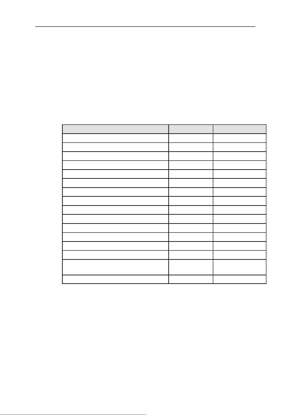
NOTE: The battery capacities quoted are minimum values.
Unit/type: Product code: Module code:
Transceiver THA–41S 0500428
system module KS4S 0200620
display module KL1 0200261
mechanics MTHA41S 0260721
**Transceiver THA–42S 0500429
Performance Specifications
system module KS4S 0200620
display module KL1 0200261
mechanics MTHA42S 0260720
Battery Pack BTH–8L (350 mAh) 0670068
Battery Pack BTH–8S (380 mAh) 0670054
Battery Pack BTH–8SM (550 mAh) 0670055
Battery Pack BTH–8H (790 mAh) 0670056
Battery Pack BTH–8HM (990 mAh) 0670057
AC Travel Charger ACH–3U (US) 0675003
AC Rapid Travel Charger ACH–4U
(US)
AC Power Supply ACS–6U (US) 0680018
**THA–42S is a future product.
0675012
Original, 12/95
Page 2–3
Page 13

THA–4S
After Sales
Performance Specifications
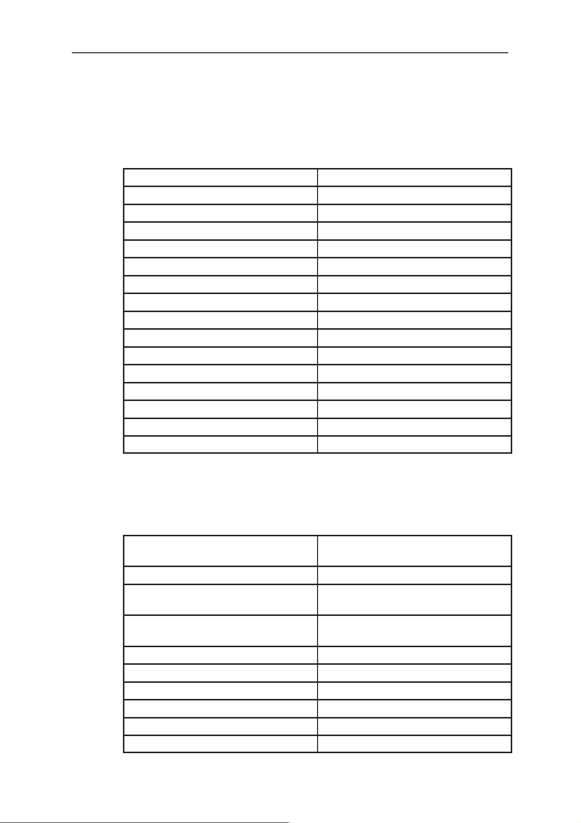
Unit/type: Product code: Module code:
AC Travel Charger ACH–3E (Euro) 0675001
AC Rapid Travel Charger ACH–4E
(Euro)
AC Power Supply ACS–6E (Euro) 0680016
Cigarette Lighter Charger LCH–2 0675013
charging module AL4
(no spare parts available)
mechanics MLCH2–2U
(no spare parts available)
Desktop Charger CHH–6 0675041
charging module DC2H 0200296
mechanics MCHH–6 0260337
Handsfree Desktop Charger CHH–7 0675040
Technical Documentation
0675008
0200044
0260094
DCXH1 module (comprising) 0200335
module DC3H 0200334
module DC4H 0200295
mechanics MCHH–7 0260338
In–car Holder MBH–9 0630009
mechanics MMBH–9 0260339
Installation kit KMKE–1 0260076
Anti–vibration Mount MKA–1 0945136
Mounting Plate MKE–1 0650007
installation kit 0260076
Cable Clip CKH–1 0620016
HF Junction Box HFJ–2 0694006
charging module BC4 0200045
mechanics 0260065
Cable Junction Box JBH–1 0630008
mechanics 0260336
Page 2–4
Original, 12/95
Page 14

After Sales
THA–4S
Technical Documentation
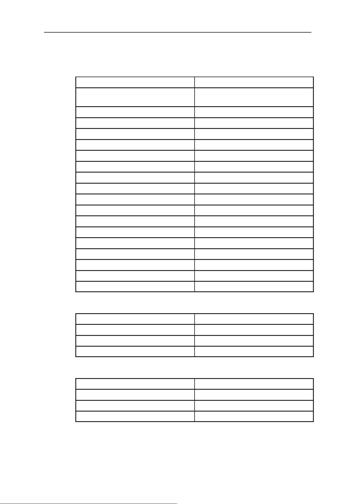
Unit/type: Product code: Module code:
Compact Handsfree Unit PHF–2 0630010
Mounting Kit for above Unit KPHF–1 0260254
Compact Handsfree Unit Charger
LCP–2
Booster BSH–2 (AMPS) 0500053
booster module BB4 0200101
mechanics 0260110
(Booster) Mounting Bracket MBM–3 0700016
mechanics 0260010
installation kit 0260108
Power Cable PCH–4 0730009
HF Microphone HFM–3 0690001
HF Speaker HFS–6 0692006
Performance Specifications
0680022
Front Mount Cable SCE–2 0730014
Extension Cable SCE–3 0730015
RF Extension Cable XRH–1 0730017
Swivel Mount HHS–1 0650008
In–car Data Cable FDP–1 0750009
Analog PCMCIA Card DTP–3 0750037
PCMCIA Data Cable DLH–2 0730043
Teleadaptor FDM–2 0750019
Cable holder CKH–1 0620016
Booster Kit BSHK–2 0082011
Original, 12/95
Page 2–5
Page 15
THA–4S
After Sales
Performance Specifications
Technical Documentation
Technical Specifications
General Specifications of THA–4S Series Transceiver
Temperature range
Operating time (with BTH–8SM)
S talk time
S standby time
Supply voltage
Nominal current consumption
S standby mode
S conversation mode
Dimensions (h x w x d)
S transceiver + BTH–8S
–30_C to +60_C
70 min
s
15 hrs
5.3 V to 9.0 V (nominal 6.0 V)
38mA
400mA
147 x 54 x 17.5 mm
S transceiver + BTH–8H
S transceiver + BTH–8SM
Weight
S transceiver + BTH–8S
S transceiver + BTH–8H
S transceiver + BTH–8SM
Electrical Specifications
Transceiver General Features
Number of channels
Duplex spacing
Channel spacing
Frequency tolerance
147 x 54 x 23.4 mm
147 x 54 x 17.5mm
200 g
345 g
215 g
AMPS: 832
NAMPS: 2412
45 MHz
AMPS: 30 kHz
NAMPS: 10kHz
AMPS:
NAMPS:
<
2.5 ppm
1ppm (AFC)
Page 2–6
Frequency control
Voice modulation
Compander
Data modulation
Data speed
Word format
synthesized
phase modulation
2:1
Manchester–coded, 16 kbaud FSK
8 kbits
BCH encoded
Original, 12/95
Page 16

After Sales
THA–4S
Technical Documentation
Receiver Branch
Frequency band 869 to 894 MHz
Rx First Intermediate Frequency 86.85 MHz
Rx Second Intermediate Frequency 450 kHz
Sensitivity AMPS: better than –116 dBm
Adjacent channel selectivity AMPS: > 16 dB
Alternate channel > 60 dB
Spurious response rejection > 60 dB
Intermodulation rejection > 65 dB
RSSI dynamic range > 60 dB
RSSI starting level < –110 dBm
Performance Specifications
(12 dBSINAD)
NAMPS: better than–118 dBm
(12 dBSINAD)
NAMPS: > 18 dB
Harmonic distortion < 5%
Blocking or desensitization outside
1Mkz from receive frequency:
band A better than –50 dBm
band B better than –23 dBm
AF DAF (2.9 kHz) 50 mV
Demod. audio phase inverted
Demodulation noise better than –32 dB
Demod. audio frequency response 6 db +1/–3db/octave pre–emphasis
Original, 12/95
Page 2–7
Page 17
THA–4S
After Sales
Performance Specifications
Transmitter Branch
Frequency band
Number of channels
PA efficiency >55%
Reference voltage for regulators
Output power at all channels
PL2
PL3
PL4
PL5
PL6
PL7
Technical Documentation
824 to 849 MHz
AMPS: 832
NAMPS: 2412
4.85 V
"
0.1 V
28 dBm
24 dBm
20 dBm
16 dBm
12 dBm
8 dBm
(tolerances +2 dB, –4 dB)
Modulation distortion
Residual modulation
TX on/off delay
Wideband data
logic 0 corresponds to dev.
logic 1 corresponds to dev.
Maximum deviation "
Synthesizer’s RX Branch
Frequency range
Output level to transmitter
Tuning voltage sensitivity
Centre channel tuning voltage
Synthesizer’s TX Branch
Frequency range
Output level to transmitter
< 5 %
< –35 dB
< 2 ms
+8 kHz ("10 %)
–8 kHz ("10 %)
12 kHz
955 to 981 MHz
+3 dBm (–2 / +4dBm)
12 – 18 MHz/V
2.5V " 0.5 V
824 to 849
MHz
+5 dBm ("2)
Page 2–8
Tuning voltage sensitivity
Centre channel tuning voltage
2 – 3 MHz/V
2.5V
"
0.5 V
Original, 12/95
Page 18

After Sales Technical Documentation
THA – 4S Series Transceiver
Chapter 3
TRANSCEIVER
OVERVIEW
Original, 12/95
Page 19

THA–4S
After Sales
Transceiver Overview
Technical Documentation
CHAPTER 3 – TRANSCEIVER OVERVIEW
CONTENTS
Page No
Introduction 3–3. . . . . . . . . . . . . . . . . . . . . . . . . . . . . . . . . . . . . . . . . . . . . . . . . . . . . . . . . . . .
System Module 3–3. . . . . . . . . . . . . . . . . . . . . . . . . . . . . . . . . . . . . . . . . . . . . . . . . . . . . . . .
Display Module 3–3. . . . . . . . . . . . . . . . . . . . . . . . . . . . . . . . . . . . . . . . . . . . . . . . . . . . . . . .
List of Figures
Figure 1: RF Block Diagram 3–4. . . . . . . . . . . . . . . . . . . . . . . . . . . . . . . . . . . . . . . . . . . . .
Figure 2: Baseband Block Diagram 3–5. . . . . . . . . . . . . . . . . . . . . . . . . . . . . . . . . . . . . . .
Page 3–2
Original, 12/95
Page 20

After Sales
THA–4S
Technical Documentation
Introduction
The THA–4S series phone is an advanced analog handportable cellular
telephone designed for operation on the Dual Mode phone AMPS/NAMPS
cellular system. The telephone contains many advanced user facilities
and is designed for ease of maintenance.
The transceiver consists of two modules: a system module and a display
module.
System Module
The system module performs the following functions:
received audio processing
transmitted audio processing
data reception and transmission
Transceiver Overview
channel selection
modulated RF signal reception and demodulation to
baseband
modulation of the Transmitter by the microphone and
data signals
application of the modulated Tx signal to the selected
power level
The system module contains a microprocessor, which controls the main
functions of the phone, and parts of the HW dependent user interface
(earphone, microphone, alarm–beeper and keyboard contacts).
For convenience the non–RF sub–systems are referred to as the
’Baseband functions’, and the RF sub–systems as the ’RF functions’.
Figures 1 and 2 show the RF and Baseband functional blocks
respectively.
The RF functions provide the RF interface with the cellular system and
demodulated audio signals to the analog sub–system. They also modulate
audio signals from the analog sub–system.
The Baseband functions cover both analog sub–systems (responsible for
all audio processing functions) and digital sub–systems (responsible for all
digital signal processing functions) and the microcontroller / software
(responsible for control and data processing functions).
Display Module
The display module comprises a supertwist–LCD, a display driver and
volume control contacts.
Original, 12/95
Page 3–3
Page 21

Page 3–4
ANT
SWITCH
EXT
ANT
ANT
869–894MHz
DUPLEXER
COUPLER
LNA
RX RX
MIXER
SAW
F1
881 MHz
25MHz bw
RX VCO
TX_LO
AMP
F2
IF FILTER
86.85MHz
30kHz bw
IF AMP
86.4MHz
P1 P2
DUAL – PLL
P0
F1
F2
X6
P3
30kHz bw
P1
IF CHIP
131.85MHz
450kHz
TX VCO
450kHz
VCTCXO
DAF
IF_FREQ
RSSI A/D
VCTCXO
RX_VCO_ADJ
TX_MOD
CLK
DATA
ENB
Transceiver Overview
Figure 1: RF Block Diagram
THA–4S
Original, 12/95
DETECT
824–849Mhz
POWER
CONTROL
NOKIA MOBILE PHONES R&D COPENHAGEN
H500 NAMPS
DRAWN
ISSUE
FILENAME
DATE
SF
6
15 – 5 –95
RF MOD. BLK
PA
4V8_TX
836MHz
TX MIXER AMP
TX MIXER
F1
F2
Power_level_set_1
Power_level_set_2
Lock_Detect
Power_level_ctrl
Technical Documentation
DRIVER
TX SAW
25MHz bw
TX_Carr_Pres
VBAT
After Sales
TX
P3
4V8_RX
RX
Vref
Page 22

After Sales
THA–4S
Technical Documentation
Figure 2: Baseband Block Diagram
ACCESSORY CONNECTOR
ESD protection
MBUS
MBUS
DRIVER
MODEM
CLOCK
CONTROLLER
(ESN)
EEPROM
XRESET
XRESET
VC
4.8 MHz
Crystal
XEXALD
XMIC
XEAR
TXDTA
RXDATA
XRESET
HOOK
N–ANTIC
CLOCK
Transceiver Overview
BUZZER
MICROPHONE
+
+
EARPIECE
VBATSW
CHRGMON
BSI
BTEMP
BATTERY
CONNECTOR
CHARGING
VC
VBAT
CHARGER
SOCKET
PSL
XRESET
CONTROL
AND CLAMP
XRESET
KEYBOARD
CSW
LCD Connector J2
LIGHTS
VBAT
CLK
V_REF
DATA
TO RF SYSTEM
IF AMP .
IF_FREQ
ENB
LOCK_DET
D/A Conv.
Power_lev_ctrl
Power_set_1
Power_set_2
A/D Conv
A/D Conv
RSSI A/D
TX_MOD
TX_Carr_Pres
RX_vco_adj
VTCXO pwm
DAF
(neg. supply)
GND
RX_VCO_ADJ
DISPLAY
Original, 12/95
DISPLAY
DRIVER
Tx
Rx
Page 3–5
Page 23

THA–4S
After Sales
Transceiver Overview
Technical Documentation
[This page intentionally left blank]
Page 3–6
Original, 12/95
Page 24

After Sales Technical Documentation
THA–41S Series Transceiver
Chapter 4
SYSTEM MODULE
Original, 12/95
Page 25

THA–4S
After Sales
System Module
Technical Documentation
CHAPTER 4 – SYSTEM MODULE
CONTENTS
Introduction 4–5. . . . . . . . . . . . . . . . . . . . . . . . . . . . . . . . . . . . . . . . . . . . . . . . . . . . . .
General 4–5. . . . . . . . . . . . . . . . . . . . . . . . . . . . . . . . . . . . . . . . . . . . . . . . . . . . . .
Special Features 4–5. . . . . . . . . . . . . . . . . . . . . . . . . . . . . . . . . . . . . . . . . . . . . .
Technical Specifications 4–5. . . . . . . . . . . . . . . . . . . . . . . . . . . . . . . . . . . . . . . . . . .
Modes of Operation 4–5. . . . . . . . . . . . . . . . . . . . . . . . . . . . . . . . . . . . . . . . . . .
External Signals and Connections 4–5. . . . . . . . . . . . . . . . . . . . . . . . . . . . . . .
System Connector J1 4–6. . . . . . . . . . . . . . . . . . . . . . . . . . . . . . . . . . . . . . .
Display Module Connector J2 4–7. . . . . . . . . . . . . . . . . . . . . . . . . . . . . . . .
Internal Signals 4–8. . . . . . . . . . . . . . . . . . . . . . . . . . . . . . . . . . . . . . . . . . . . . . .
Page No
Connections between RF and Baseband 4–8. . . . . . . . . . . . . . . . . . . . . .
Functional Description 4–9. . . . . . . . . . . . . . . . . . . . . . . . . . . . . . . . . . . . . . . . . . . .
Logic Circuit Description 4–9. . . . . . . . . . . . . . . . . . . . . . . . . . . . . . . . . . . . . . .
General 4–9. . . . . . . . . . . . . . . . . . . . . . . . . . . . . . . . . . . . . . . . . . . . . . . . . . .
Microcontroller 4–9. . . . . . . . . . . . . . . . . . . . . . . . . . . . . . . . . . . . . . . . . . . . .
Microprocessor D101 Pinout 4–9. . . . . . . . . . . . . . . . . . . . . . . . . . . . . . . . .
Modem 4–12. . . . . . . . . . . . . . . . . . . . . . . . . . . . . . . . . . . . . . . . . . . . . . . . . . .
Modem (D100) Signals 4–12. . . . . . . . . . . . . . . . . . . . . . . . . . . . . . . . . . . . . .
Regulators 4–12. . . . . . . . . . . . . . . . . . . . . . . . . . . . . . . . . . . . . . . . . . . . . . . .
PSL N101 Signals 4–13. . . . . . . . . . . . . . . . . . . . . . . . . . . . . . . . . . . . . . . . . .
Memories 4–13. . . . . . . . . . . . . . . . . . . . . . . . . . . . . . . . . . . . . . . . . . . . . . . . .
EEPROM D102 Signals 4–13. . . . . . . . . . . . . . . . . . . . . . . . . . . . . . . . . . . . .
Charging Control 4–14. . . . . . . . . . . . . . . . . . . . . . . . . . . . . . . . . . . . . . . . . . .
Display Lighting 4–14. . . . . . . . . . . . . . . . . . . . . . . . . . . . . . . . . . . . . . . . . . . .
Audio Circuit Description 4–15. . . . . . . . . . . . . . . . . . . . . . . . . . . . . . . . . . . . . . .
Transmit (TX) Signal Path 4–15. . . . . . . . . . . . . . . . . . . . . . . . . . . . . . . . . . .
Receiver (RX) Audio Signal Path 4–15. . . . . . . . . . . . . . . . . . . . . . . . . . . .
RF Circuit Description 4–16. . . . . . . . . . . . . . . . . . . . . . . . . . . . . . . . . . . . . . . . . .
Page 4–2
Receiver 4–16. . . . . . . . . . . . . . . . . . . . . . . . . . . . . . . . . . . . . . . . . . . . . . . . . .
RX Synthesizer 4–17. . . . . . . . . . . . . . . . . . . . . . . . . . . . . . . . . . . . . . . . . . . .
Transmitter 4–18. . . . . . . . . . . . . . . . . . . . . . . . . . . . . . . . . . . . . . . . . . . . . . . .
Directional coupler circuitry 4–19. . . . . . . . . . . . . . . . . . . . . . . . . . . . . . . . . .
Power Control circuitry. 4–19. . . . . . . . . . . . . . . . . . . . . . . . . . . . . . . . . . . . .
TX Synthesizer 4–19. . . . . . . . . . . . . . . . . . . . . . . . . . . . . . . . . . . . . . . . . . . .
Original, 12/95
Page 26

After Sales
THA–4S
Technical Documentation
Parts list (KS4S Iss. 8.2) 4–21. . . . . . . . . . . . . . . . . . . . . . . . . . . . . . . . . . . . . . . . . .
Parts List – (Display Module KL1) 4–34. . . . . . . . . . . . . . . . . . . . . . . . . . . . . . . . . .
List of Figures
Figure 1: BaseBand Circuit Diagram 4–35. . . . . . . . . . . . . . . . . . . . . . . . . . . . . . . .
Figure 2: RF Circuit Diagram 4–36. . . . . . . . . . . . . . . . . . . . . . . . . . . . . . . . . . . . . . .
Figure 3: Keypad & Display Circuit Diagram 4–37. . . . . . . . . . . . . . . . . . . . . . . . .
Figure 4: Component Layout Diagrams (Bottom) 4–38. . . . . . . . . . . . . . . . . . . . .
Figure 5: Component Layout Diagram (Top) 4–39. . . . . . . . . . . . . . . . . . . . . . . . .
System Module
Original, 12/95
Page 4–3
Page 27

THA–4S
After Sales
System Module
Technical Documentation
[This page intentionally left blank]
Page 4–4
Original, 12/95
Page 28

After Sales
THA–4S
Technical Documentation
Introduction
General
The system module controls the operation of the internal parts of the
phone. Its task is to control the user interface, i.e. LCD driver, keyboard,
and audio interface functions. The module performs all signalling towards
the system and carries out audio–frequency signal processing. In addition,
it controls charging, the operation of the transceiver and also stores tuning
data for the phone.
The RF unit receives and demodulates the radio frequency signal from the
base station and transmits the modulated signal to the base station.
Special Features
Accessory connector at bottom, e.g. for RF booster and
handsfree junction box.
RF connector at bottom, with RF switch for connection
to accessories.
System Module
Extra lines to processor and ordinary lines with
additional functions to communicate with accessories.
Technical Specifications
Modes of Operation
As well as charging the module has two other active operating modes as
follows:
Conversation mode
Listening mode
In the conversation mode all IC’s are active.
In the listening mode some blocks of the audio IC N_ANTIC are in
standby state. The transmitter and the TX synthesizer are switched off.
External Signals and Connections
The module has two external connectors, the system connector and the
display module connector. The system connector incorporates the
charging connector, the accessory connector and the external antenna
connector.
Original, 12/95
Page 4–5
Page 29

THA–4S
After Sales
System Module
System Connector J1
Pin Name Description
1 VC Charger Input +vc
2 XEXAUD Booster power control output.
3 HOOK On hook indication for handsfree operation.
4 XEAR External earphone signal.
5 0V 0V for both charger and audio.
6 VC Charger input +vc
7 MBUS Bidirectional asynchronous data bus.
8 0V 0V for both charger and audio
9 XMIC External microphone signal
10 0V 0V for both charger and audio
11 0V For charger
Technical Documentation
12 VC Charger input +ve
13 VC Charger input +ve
14 0V 0V for charger
15 0V 0V
16 RF RF signal to duplex filter
17 RF RF signal to antenna
18 0V 0V
19 VBAT Battery voltage
20 BTEMP Battery temperature measurement, 27k pull–up
resistor to 4.85V.
21 BSI Battery size indication, 100k pull–up resistor to
+4.85V
22 0V 0V for battery
Page 4–6
Original, 12/95
Page 30

After Sales
THA–4S
Technical Documentation
Display Module Connector J2
Pin Name Description
1 ROW1 Row 1 of keypad matrix.
2 COL0 Column 0 of keypad matrix
3 ROW0 Row 0 of keypad matrix
4 COL3 Column 3 of keypad matrix
5 VBAT Battery voltage power for LEDs
6 LCD
LIGHTS
7 LCD_CLK Clock for LCD driver
8 LCD_RES Reset for LCD driver
9 XLCDEN LCD driver for chip enable
10 C_XD Command/No data
11 SCL Serial data clock
System Module
Current supply for LCD backlights
12 VL2 Supply voltage for LCD driver
13 XBUSY Busy signal from LCD driver
14 0V 0V power connection
15 SDA Serial data
16 V_LCD Negative voltage for LCD
17 NC
18 NC
NOTE: NC = No Connection
Original, 12/95
Page 4–7
Page 31

THA–4S
After Sales
System Module
Technical Documentation
Internal Signals
Connections between RF and Baseband
Pin Name Description
VBATT Battery Supply Voltage
Vref Reference Voltage (4.85 Vdc nom.)
GND power Supply Ground
VCTCXO PWM Control for AFC purpose
CLK Synthesizer Serial Clock
DATA Synthesizer Serial Data
ENB Synthesizer Enable
Lock_Detect Detection of TX Synthesizer lock status
DAF Demodulated received audio and data
RSSI A/D Received signal strength indicator
IF_FREQ 2. Intermediate frequency for AFC purpose
RX_VCO_ADJ Negative adjustable voltage for tuning RX VCO
TX_mod Transmit modulation output for TX_VCO
Power_level_set_1 Power Control Bit 1
Power_level_set_2 Power Control Bit 2
Power_level_ctrl DAC value for setting the correct output power
TX_Carr_Pres TX carrier present – TX transmitting or not– used for
fault detection
Page 4–8
Original, 12/95
Page 32

After Sales
THA–4S
Technical Documentation
Functional Description
Logic Circuit Description
General
The audio/logic unit consists of 5 IC’s: controller D101, modem D100,
audio N_ANTIC N100, memory D102, regulator PSL N101.
Microcontroller
Controller D101 has six 8–bit I/O ports (Ports 1, 3, 4, 5, 7 and 9), one
5–bit port (Port 2), one 4–bit I/O port (Port 6) an 10–bit 8–channel A/D
converter (Port 8), three PWM timers, serial communication interface. All
memory (124 kB ROM, 4 kB RAM), except EEPROM, is located in the
controller.
Microprocessor D101 Pinout
System Module
Pin Name I/O Description
1 A1 O Address bit1 for modem
2 XCS O Chip select for modem
3 XRD O Read Strobe to Modem
4 XWR O Write Strobe to Modem
5 VL1 I Digital supply voltage
6 VL1 I Mode Select – ’1’
7 VL1 I ––”–– ’1’
8 VL1 I ––”–– ’1’
9 XSTDBY I HW Standby Mode Input
10 XRES I Reset Input
11 NMI I Modem Interrupt (non maskable)
12 DGND I Digital Ground
13 D0 I/O Data bit 0 to modem
14 D1 I/O
15 D2 I/O
16 D3 I/O ––”––
17 D4 I/O
18 D5 I/O
29 D6 I/O
20 D7 I/O Data bit 7 to modem
21 RX_D/A 1 O MSB in data setup to RX_VCO_ADJ (negative
supply)
Original, 12/95
Page 4–9
Page 33

THA–4S
After Sales
System Module
DescriptionI/ONamePin
22 RX_D/A 2 O
23 RX_D/A 3 O LSB in data setup to RX_VCO_ADJ (negative
supply)
24 NC O Reset to Output High
25 NC O Reset to Output High
26 IF–Amplifier
supply enable
27 Power_lev-
el_set_1
28 Power_lev-
el_set_2
29 DGND Digital Ground
O Reset to ’1’ Turn to ’0’ when on a control channel
and in stdby mode.
PA stage power controll bit 1
PA stage power controll bit 2
Technical Documentation
30 ROW 0 Keypad Input and power up control
31 ROW 1 Keypad Input
32 ROW 2 ––”––
33 ROW 3 ––”––
34 ROW 4 ––”––
35 ROW 5 ––”––
36 ROW 6 ––”––
37 OUT_T O Time OUT in NMT – Used for Buzzer volumen
38 COL 0 Keypad Output and power up control
39 COL 1 Keypad Output
40 COL 2 Keypad Output
41 COL 3 Keypad Output
42 VL1 Digital supply voltage
43 NC O Reset to Output High
44 LIGHTS O Keypad and LCD Lights on/off Reset to ’0’
45 NC O Reset to Output High
46 MBUSNF MBUS net free timer input
47 CLK O Synthesizer clock
48 DATA O Synthesizer data
49 ENB O Synthesizer enable
50 Charge en-
able
Page 4–10
O Call on charging when ’0’
Original, 12/95
Page 34

After Sales
THA–4S
Technical Documentation
DescriptionI/ONamePin
51 AGND I Analog Ground – for A/D converter
52 VBATSW I Battery Voltage Monitor
53 CHRGMON I Charger Voltage monitor
54 RSSI I Received signal Strength Indicator A/D conv. In-
put
55 TX carr
pres
56 BTEMP I Battery Temperature A/D–converter input
57 AD_5 I Hook detection input from accessory connector
58 BSI I Battery Size Indication
59 HFJCON I Hands Free Junction Box sensor
60 Vref I A/D converter Reference Voltage
I TX carr pres A/D input
System Module
61 ANTSDA I/O N_ANTIC Serial Data
62 Lock_de-
tect
63 XEXAUD O
64 VCTCXO O
65 CSW O
66 Transmit Serial Data to M2BUS
67 Received Serial Data from M2BUS
68 SCL I/O IIC Synchronous clock for EEPROM and LCD
69 HB_EXTAL I MCU clk from modem 4.8 MHz
70 NC
71 DGND I Digital Ground
72 ACLK O Analog Clk – phi Clk/2 for N_ANTIC (2.4 MHz)
I TX synthesizer lock detector
PWM Output to Accessory Connector – Booster
PWM1
Frequency trim control voltage for VCTCXO
PWM2
(Charger Switch) Pulse Width Modulated Char-
PWM3
ger Control
serial data
73 XBUSY I Busy signal from the LCD Driver
74 XLCDEN O LCD Driver Enable/Select
75 C_XD O LCD Driver and EEPROM Multiplexer control
76 CSCK I/O N_ANTIC Serial Clk (Serially interface lock)
77 CLK STEP O Renamed from SYN CLK. Used to pull in the
baseband crystal osc. frequency.
Original, 12/95
Page 4–11
Page 35

THA–4S
After Sales
System Module
DescriptionI/ONamePin
78 NMI I Modem Interrupt (non maskable)
79 SDA I/O IIC Serial Data for EEPROM and LCD
80 A0 O Adress bit 0 for modem
Modem
The NAT D100 is a single VLSI chip modem used for the NAMPS/TACS
mobile telephone. It implements a Manchester data receiver–transmitter,
and provides supervisory audio tone (SAT) and signalling tone (ST)
functions. Received messages are corrected and checked by 3/5 voting
and BTH decoding blocks.
Modem (D100) Signals
Name Description
INT interrupt output to controller
Technical Documentation
Regulators
Regulator PSL (N101) is the power supply circuit for battery operated
applications requiring separate voltage supplies (for the microcontroller,
logic and analog functions). It has three voltage regulators (VL1, VL2 and
VA), a reference voltage output (VREF), power on/off and reset logic, and
a watch dog, in addition to circuitry for supply voltage and battery charger
monitoring functions.
XCLR reset input
XCS chip select from controller
D0–7 data bus to controller
A0–1 address lines for register selection
XRD, XWR read/write control from controller
DI data input from RF unit
DO data output to ANTIC
C1–2 clock generator
CLOCKOUT system clock output to controller and PIC
DAC 0 dac o/p to Power_Level_Ctrl.
Page 4–12
Original, 12/95
Page 36

After Sales
THA–4S
Technical Documentation
PSL N101 Signals
Name Description
VBAT battery voltage input
VREF voltage reference output (+4.85V
VL1 logic voltage output (+4.8 V) for
VL2 logic voltage output (+4.8 V) for
VA analog voltage output (+4.8 V)
VBATSW switched VBAT voltage
XPWRON power on control input from key-
XPWROFF power off control from controller
System Module
2 %)
controller
other logic
board
(watchdog)
Memories
XRESET reset control output for logic
XSTBY standby control for controller
CHRGDET battery charger detection input
DETIN supply voltage detection input
CRESET connection for external timing ca-
pacitor defining reset signal delay
COFF connection for an external timing
capacitor defining power off delay
CPOR connection for external capacitor
for controlled power on master reset
GND ground (analog/logic)
EEPROM D102 comprises non–volatile memory into which are stored the
tuning data for the phone. In addition, D102 contains 99 short code
memory locations to retain user selectable phone numbers. EEPROM
data signal SDA is fed to the display modules multiplexer, where the signal
is divided into two SDA lines.
EEPROM D102 Signals
Name Description
SCL IIC bus clock
SDA IIC bus data
Original, 12/95
Page 4–13
Page 37

THA–4S
After Sales
System Module
Charging Control
The charging circuit is fully controlled via software determined from
Battery Size Indicator and Battery TEMPerature A/D converter inputs.
The BTEMP is derived from an incorporated thermistor in the battery pack
and converted to real temperature via a table in SW, which decides where
the critical limits for charging is.
The BSI resistor is built in the battery package and designed to give an
A/D reading of 344 – (1.63 V at A/D converter) per Ah battery capacity.
The actual capacity is then calculated from the reading to mAh by:
A/D*32/11.
In principle the charging circuit contains a basic serial power switch
controlled via a pair of parallel transistors responsible for a controlled
power up when a charger is inserted. For approx. 1s the PSL is the
controller and turns on the series switch (XRES low ) to ensure that a flat
battery is sufficiently charged before the MCU can take over. When
powered up the MCU can pulse width modulate the PW3 line so that a
fast or slow charge can take place and determine which charger is
connected. The MCU makes a decision dependent of the chrgmon value
(A/D converter).
Technical Documentation
Display Lighting
Display lighting is generated by V414, V419,V415,R400, R401, and R402.
The lighting is controlled by the controller.
Page 4–14
Original, 12/95
Page 38

After Sales
THA–4S
Technical Documentation
Audio Circuit Description
Transmit (TX) Signal Path
The TX audio signal is processed in the N_ANTIC and fed, via the MOD
line, to the synthesizer. N_ANTIC contains the following stages for TX
signal processing:
Name Description
MICAMP Signal from the microphone is fed to this stage and
MUX TX source selection (EXMIC/MIC/DTMF/MUTED)
TXAAFIL Anti alias filter (see N_ANTIC specification)
BANDPASS (see N_ANTIC specification)
TXATT For handsfree mode of operation
COMPRESSOR 2:1 syllabic compressor
System Module
amplified
PREEMP Pre–emphasis filter
AGC Soft Limiter
LIMU Hard limiter
LOWPASS Low pass notch filter
POSTFIL Second order Sallen–Key filter
SUMSTAGE Data from modem is summed in here
TRCOMP Modulation sensitivity compensation
Receiver (RX) Audio Signal Path
The demodulated audio signal (DAF) from the receiver is fed to the
N_ANTIC circuit which contains a software controlled receiver and
compensation amplifier. The output of this stage drives the modem IC and
the remaining N_ANTIC RX signal processing stages.
Name Description
MUX RX source selection (DTMF/DAF1/DAF2)
RXAAFIL Anti alias filter
RXFIL Second order Sallen–Key filter
EXP 2:1 Syllabic Expander
VOLUME Volume Control Amplifier
RXATT For Handsfree mode
EARPAMP The earphone amplifier is a single input, differential
ACCAMP Accessory amplifier – buffer for XEAR output
Original, 12/95
output amplifier for a ceramic earpiece
Page 4–15
Page 39

THA–4S
After Sales
System Module
RF Circuit Description
Receiver
The receiver is a dual–conversion superheterodyne using two
intermediate frequencies, 86.85 MHz and 450 kHz.
The RF signal from the duplexer RX port is applied to the Low Noise
amplifier. The amplifier is realized with transistor V200. Amplifier stage
input matching is accomplished by C201 and L217. R200 and R201 are
used for biasing. Output matching is carried out by L216, R211 and C325.
Components C326 and C329 are used for RF bypassing. C200 and C202
are for amplifier stabilization. The Low Noise amplifier and the IF circuit
are connected in series with R202 so that the same supply current is
passed through both stages. The signal is then filtered with Z202.
The filter is followed by a single balanced diode mixer, realized with
C207,C208, Z205, Z204, Z203 and V201. Input matching from the Rx
SAW filter is realized by C205 and L201.
Technical Documentation
The signal is then filtered with a saw filter Z206. Input and output
impedances are 600 ohm // 3pF. The filter and the IF amplifier stage are
matched by C210 and L203.
The IF amplifier is realized with transistor V202; R205 and R206 are used
for biasing, R203 and C209 are for amplifier stabilization. The IF amplifier
stage and the second mixer are matched by R204 and C220.
The second mixer, the oscillator transistor, IF amplifier, LIM amplifier,
quadrature detector and audio amplifier are all integrated in the circuit
N201. The second LO frequency, 86.4 MHz, is realized by multiplying
VCTCXO (14.4MHz) six times. This multiplier is realized with transistor
V225, R226 and R303 being used for biasing. R299 and C324 are for
stabilization.
L215, C323 and C219 is the bandpass filter for 86.4 MHz. C265 and C219
are used for DC blocking. L204 and C215, are connected to OSCOUT.
After the mixer, the 450 kHz IF signal is fed to the multiplexer circuit N200.
Z207 is a narrow ceramic filter for NAMPS and Z208 is a wide ceramic
filter for AMPS. A multiplexer circuit is used to switch between these
filters. The LIM amplifier output signal is fed through C223 to a
quadrature detector. After this, the signal is phase shifted by resonance
circuit C225, R214 and L205.
Page 4–16
Signal DAF is low pass filtered by R212, C222 and R213. The 2nd IF, DAF
and RSSI signal (450 kHz) is fed to the audio/logic unit.
Original, 12/95
Page 40

After Sales
THA–4S
Technical Documentation
RX Synthesizer
The first injection frequency (1st LO) is obtained from a voltage controlled
oscillator (VCO) V205. The VCO output signal is amplified by transistor
V204 and fed to the receiver mixer via Z05. The injection level required by
the receiver mixer is nominally +3 dBm. In addition, the signal is fed
through C230 to a buffer amplifier and divider chain in the synthesizer
circuit N202 and via R297 to an amplifier V212 in the TX synthesizer.
The VCO output frequency is locked to a stable reference frequency by
means of a phase locked loop (PLL) with N202. N202 is a dual–
synthesizer circuit, comprising; two independent programmable main
dividers, phase detectors, chargepumps, a common programmable
reference divider, a voltage doubler for the chargepump supply and 3
programmable output ports. Half of the circuit is used for the RX
synthesizer, the other half for the TX synthesizer.
The internal main dividers of N202 are programmed with 21 bits each,
which are transferred serially on the SDATA (synthesizer data) line from
the processor into an internal shift register also located in N202. Data
transfer is timed with CLK clock pulses. After the transfer, the ENB (RX
synthesizer latch enable) line goes high and the data is latched to N202.
System Module
The VCO frequency is divided down and compared with a highly stable
comparison frequency, derived from a reference oscillator, by a phase
comparator in the PLL circuit (N202). The phase comparator output
switches a chargepump, controlling the VCO frequency, by means of a DC
voltage through the loop filter. This keeps the divided frequency applied to
the phase comparator equal to the fixed comparison frequency.
The comparison frequency is 10 kHz. It is not always equal to the channel
spacing (AMPS: 30 kHz, NAMPS: 10 kHz). This reference frequency is
obtained from a voltage controlled, temperature compensated, crystal
oscillator (VCTCXO) G200. Oscillator frequency is 14.4 MHz. The
VCTCXO frequency is divided by 1440 in AMPS and NAMPS.
The chargepump output at pin 3 delivers positive or negative current
pulses to the loop filter, consisting of R229, R228, R227, C250, C248,
C247 and C246. This converts these pulses to a DC voltage and filters the
remaining ripple. The DC control voltage is routed to the VCO varicap
diode V206 and so controls the VCO frequency.
If the VCO frequency is too low, the chargepump will deliver positive
current to the loop filter. Thereafter the DC control voltage and the VCO
frequency will go up. When the VCO frequency is correct and the
synthesizer is locked to the desired frequency (channel), the chargepump
output is in a high impedance state.
The VCO is a Clapp type oscillator. The oscillator’s resonant frequency is
determined by the circuitry Z209, C245, C239, C240, C241, C237 plus the
control voltage at the cathode of varicap V206. The centre frequency of
the VCO is adjusted by changing the negative voltage on the anode of
V206.
Original, 12/95
Page 4–17
Page 41

THA–4S
After Sales
System Module
The VCO signal is amplified by buffer amplifier V204. This amplifier
produces +3 dBm to the first mixer via Z06. The same buffer produces a
level of –15 dBm to the divider–buffer in N202 and –10dBm to the
amplifier V212 in the TX synthesizer via C230.
Transmitter
The transmitter concept consist of following circuit blocks: TX–mixer,
TX–mixer amplifier, TX–SAW filter, Driver–, PA–module–, Lowpass filter,
Directional coupler– and the Power Control circuitry.
TX MIXER.
The TX–frequency is obtained by mixing the RX–VCO signal with the
TX–VCO signal. The TX–mixer is implemented as a single balanced diode
(V211) mixer, where the mixer transformer is implemented in the PCB .
TX MIXER AMPLIFIER.
Technical Documentation
To compensate for the TX mixer conversion loss and to achieve a proper
impedance match to the SAW filter, an amplifier is needed. The matching
and amplification is done by a single bipolar transistor (V213) stage.
TX SAW FILTER.
To reduce the spurious effects from the TX mixer, the output frequency
bandwidth of both the TX mixer and Mixer buffer output is limited. This
prevents problems with the TX–VCO harmonics at the antenna and
quieting in the receiver. The TX signal spectrum is limited by a SAW filter
(Z210) before it is fed into the following driver stage.
DRIVER CIRCUITRY.
To obtain sufficient power drive level to the Power module and avoid the
VCO kicking in during PA start up, a single bipolar transistor (V219)
amplifier stage is needed.
PA MODULE CIRCUITRY.
The output power circuitry consist of a three stages Gallium Arsenide
Heterojunction bipolar transistor high power amplifier IC (N203) : The
input stage is operating class A, and the second stage is operating in
class AB, and the final stage is operating in class B.
Page 4–18
The first two stages are easy to match with external drain matching
networks. The output stage has a relative low resistive output impedance
and requires a proper matching network to obtain a power efficient and
stable PA stage. No additional Lowpass filter is required to remove the
harmonics of the transmitter between the TX power output stage and the
duplexer in order to fulfil the TX spurious rejection specification.
Original, 12/95
Page 42

After Sales
THA–4S
Technical Documentation
The module is based on GaAs technology and does not require any
negative gate voltage, giving a simpler bias circuitry and safer
construction. The power module has an internal bias circuit, which makes
it possible to control the gain of the module with digital logic and analogue
level signals: two bits are used for controlling the gain in ten dB steps: an
analogue input signal is used to power the module ‘On’ and ‘Off’ and
control the module’s RF output power level. All stages are supplied from
and connected directly to the battery line.
The PA–IC is a SMT type and the grounding of the PCB will be used as a
heat sink for the power stage.
Directional coupler circuitry
A voltage proportional to the output power is rectified from a directional
coupler. This rectified voltage is fed into the feedback input of power
control circuitry.
System Module
Power Control circuitry.
The power control circuit is biased of a discrete build differential transistor
(V215) amplifier stage, where the rectified voltage is fed to the negative
input and compared with the reference voltage connected to the positive
input. The reference voltage is a lowpass filtered D/A signal from the
baseband circuitry. The differential amplifier adjusts the collector voltage
of serial the transistor (V216) to the reference voltage and the voltage
proportional to the output power are equal.
TX Synthesizer
The transmitter synthesizer generates a frequency modulated transmitter
signal for the transmitter section.
The TX offset synthesizer consists of a 131.85 MHz PLL circuit, passive
loop filter and a VCO equipped with a chip coil resonator. Modulation is
brought to the VCO.
The TX signal is obtained by mixing the signals of offset synthesizer and
RX synthesizer with a single balanced diode mixer. From the mixer the
–15 dBm level is fed to the amplifier V213. The TX signal is filtered with a
SAW filter before inputting it to the transmitter.
The VCO is a Clapp type oscillator. The oscillator’s resonance frequency
is determined by the circuitry L210, C273, C268, V208, C274, and C275.
The center frequency of the resonance circuit is not adjustable (By
increasing or decreasing the capacitor C273 the resonance frequency can
be changed). The VCO signal is amplified by V209 and fed to the PLL
circuit and to the mixer.
Original, 12/95
Page 4–19
Page 43

THA–4S
After Sales
System Module
The transceiver unit is equipped with an AFC function, i.e. it uses the
incoming receive signal from the base station as a frequency reference.
The control loop consists of the receiver, the IF counter in the modem
(D100), CPU (D101), an 8–bit D/A converter in the modem and the
VCTCXO, which is used as a reference oscillator for the synthesizer.
The 2nd IF signal (450 kHz) from the receiver is fed to the audio/logic unit,
where it is buffered and fed to the modem. The IF counter counts the
received frequency. If the frequency differs from the programmed value,
the CPU adjusts the frequency of the VCTCXO by changing the output
voltage of the D/A converter. This adjustment continues until the desired
receive frequency is achieved. AFC is not active during a channel scan.
Regulator transistors V221 and V222 form a voltage regulator for the
receiver. It is realized with discrete transistors because the output noise
has to be very low. The 4.85V reference voltage (VREF) comes from the
logic module, and is used to shut down VRX when the radio is switched
off.
Technical Documentation
Transistor V217 and V226 form a voltage regulator for the transmitter
path. The output voltage can be switched on and off by output port P3 of
N202 via current boosting transistor V223.
Page 4–20
Original, 12/95
Page 44

After Sales
THA–4S
Technical Documentation
System Module
Parts list KS4S (EDMS Iss. 8.2)
ITEM CODE DESCRIPTION VALUE TYPE
R100 1411437 Chip resistor 56 5 % 0.12 W 1206
R101 1411437 Chip resistor 56 5 % 0.12 W 1206
R102 1411437 Chip resistor 56 5 % 0.12 W 1206
R103 1430778 Chip resistor 10 k 5 % 0.063 W 0402
R104 1411388 Chip resistor 33 5 % 0.12 W 1206
R105 1430754 Chip resistor 1.0 k 5 % 0.063 W 0402
R106 1430778 Chip resistor 10 k 5 % 0.063 W 0402
R107 1430754 Chip resistor 1.0 k 5 % 0.063 W 0402
R108 1430792 Chip resistor 33 k 5 % 0.063 W 0402
R109 1430792 Chip resistor 33 k 5 % 0.063 W 0402
R110 1430778 Chip resistor 10 k 5 % 0.063 W 0402
R111 1430804 Chip resistor 100 k 5 % 0.063 W 0402
R112 1430762 Chip resistor 2.2 k 5 % 0.063 W 0402
R113 1430796 Chip resistor 47 k 5 % 0.063 W 0402
R114 1430828 Chip resistor 820 k 5 % 0.063 W 0402
R115 1430754 Chip resistor 1.0 k 5 % 0.063 W 0402
R116 1430746 Chip resistor 560 5 % 0.063 W 0402
R117 1430796 Chip resistor 47 k 5 % 0.063 W 0402
R118 1430806 Chip resistor 120 k 5 % 0.063 W 0402
R119 1430792 Chip resistor 33 k 5 % 0.063 W 0402
R120 1430804 Chip resistor 100 k 5 % 0.063 W 0402
R121 1430754 Chip resistor 1.0 k 5 % 0.063 W 0402
R122 1430780 Chip resistor 12 k 5 % 0.063 W 0402
R123 1430804 Chip resistor 100 k 5 % 0.063 W 0402
R124 1430804 Chip resistor 100 k 5 % 0.063 W 0402
R125 1430804 Chip resistor 100 k 5 % 0.063 W 0402
R126 1430804 Chip resistor 100 k 5 % 0.063 W 0402
R127 1430778 Chip resistor 10 k 5 % 0.063 W 0402
R128 1430770 Chip resistor 4.7 k 5 % 0.063 W 0402
R129 1430808 Chip resistor 150 k 5 % 0.063 W 0402
R130 1430770 Chip resistor 4.7 k 5 % 0.063 W 0402
R131 1413829 Chip resistor 10 5 % 0.1 W 0805
R132 1430804 Chip resistor 100 k 5 % 0.063 W 0402
R133 1430804 Chip resistor 100 k 5 % 0.063 W 0402
R134 1430804 Chip resistor 100 k 5 % 0.063 W 0402
R135 1430804 Chip resistor 100 k 5 % 0.063 W 0402
R136 1430804 Chip resistor 100 k 5 % 0.063 W 0402
R137 1430710 Chip resistor 22 5 % 0.063 W 0402
R138 1430804 Chip resistor 100 k 5 % 0.063 W 0402
Original, 12/95
Page 4–21
Page 45

THA–4S
After Sales
System Module
R139 1430796 Chip resistor 47 k 5 % 0.063 W 0402
R140 1430796 Chip resistor 47 k 5 % 0.063 W 0402
R141 1430828 Chip resistor 820 k 5 % 0.063 W 0402
R142 1430804 Chip resistor 100 k 5 % 0.063 W 0402
R143 1430804 Chip resistor 100 k 5 % 0.063 W 0402
R144 1430812 Chip resistor 220 k 5 % 0.063 W 0402
R145 1430248 Chip resistor 3.9 k 2 % 0.063 W 0603
R146 1430250 Chip resistor 4.7 k 2 % 0.063 W 0603
R147 1430790 Chip resistor 27 k 5 % 0.063 W 0402
R148 1430254 Chip resistor 6.8 k 2 % 0.063 W 0603
R149 1430746 Chip resistor 560 5 % 0.063 W 0402
R150 1430746 Chip resistor 560 5 % 0.063 W 0402
R151 1430776 Chip resistor 8.2 k 5 % 0.063 W 0402
R152 1430762 Chip resistor 2.2 k 5 % 0.063 W 0402
R153 1430762 Chip resistor 2.2 k 5 % 0.063 W 0402
R154 1430778 Chip resistor 10 k 5 % 0.063 W 0402
R155 1430762 Chip resistor 2.2 k 5 % 0.063 W 0402
R156 1430788 Chip resistor 22 k 5 % 0.063 W 0402
R157 1430790 Chip resistor 27 k 5 % 0.063 W 0402
R158 1430762 Chip resistor 2.2 k 5 % 0.063 W 0402
R159 1430816 Chip resistor 330 k 5 % 0.063 W 0402
R160 1430812 Chip resistor 220 k 5 % 0.063 W 0402
R161 1430294 Chip resistor 220 k 2 % 0.063 W 0603
R162 1413829 Chip resistor 10 5 % 0.1 W 0805
R163 1430730 Chip resistor 150 5 % 0.063 W 0402
R164 1430280 Chip resistor 100 k 2 % 0.063 W 0603
R165 1430816 Chip resistor 330 k 5 % 0.063 W 0402
R166 1430818 Chip resistor 390 k 5 % 0.063 W 0402
R167 1430796 Chip resistor 47 k 5 % 0.063 W 0402
R168 1430804 Chip resistor 100 k 5 % 0.063 W 0402
R169 1430804 Chip resistor 100 k 5 % 0.063 W 0402
R170 1430790 Chip resistor 27 k 5 % 0.063 W 0402
R171 1430792 Chip resistor 33 k 5 % 0.063 W 0402
R172 1430788 Chip resistor 22 k 5 % 0.063 W 0402
R173 1430792 Chip resistor 33 k 5 % 0.063 W 0402
R174 1430754 Chip resistor 1.0 k 5 % 0.063 W 0402
R175 1430788 Chip resistor 22 k 5 % 0.063 W 0402
R176 1430808 Chip resistor 150 k 5 % 0.063 W 0402
R177 1430796 Chip resistor 47 k 5 % 0.063 W 0402
R178 1430778 Chip resistor 10 k 5 % 0.063 W 0402
R179 1430804 Chip resistor 100 k 5 % 0.063 W 0402
R180 1430792 Chip resistor 33 k 5 % 0.063 W 0402
Technical Documentation
Page 4–22
Original, 12/95
Page 46

After Sales
THA–4S
Technical Documentation
R181 1430788 Chip resistor 22 k 5 % 0.063 W 0402
R182 1430746 Chip resistor 560 5 % 0.063 W 0402
R183 1430746 Chip resistor 560 5 % 0.063 W 0402
R184 1430774 Chip resistor 6.8 k 5 % 0.063 W 0402
R185 1430774 Chip resistor 6.8 k 5 % 0.063 W 0402
R186 1430792 Chip resistor 33 k 5 % 0.063 W 0402
R187 1430754 Chip resistor 1.0 k 5 % 0.063 W 0402
R188 1430754 Chip resistor 1.0 k 5 % 0.063 W 0402
R189 1430778 Chip resistor 10 k 5 % 0.063 W 0402
R190 1430804 Chip resistor 100 k 5 % 0.063 W 0402
R191 1430804 Chip resistor 100 k 5 % 0.063 W 0402
R192 1430778 Chip resistor 10 k 5 % 0.063 W 0402
R193 1430734 Chip resistor 220 5 % 0.063 W 0402
R194 1430778 Chip resistor 10 k 5 % 0.063 W 0402
R195 1430778 Chip resistor 10 k 5 % 0.063 W 0402
R196 1430700 Chip resistor 10 5 % 0.063 W 0402
R197 1430792 Chip resistor 33 k 5 % 0.063 W 0402
R200 1430770 Chip resistor 4.7 k 5 % 0.063 W 0402
R201 1430774 Chip resistor 6.8 k 5 % 0.063 W 0402
R202 1430700 Chip resistor 10 5 % 0.063 W 0402
R203 1430726 Chip resistor 100 5 % 0.063 W 0402
R204 1430754 Chip resistor 1.0 k 5 % 0.063 W 0402
R205 1430790 Chip resistor 27 k 5 % 0.063 W 0402
R206 1430774 Chip resistor 6.8 k 5 % 0.063 W 0402
R207 1430778 Chip resistor 10 k 5 % 0.063 W 0402
R208 1430718 Chip resistor 47 5 % 0.063 W 0402
R211 1430744 Chip resistor 470 5 % 0.063 W 0402
R212 1430762 Chip resistor 2.2 k 5 % 0.063 W 0402
R213 1430774 Chip resistor 6.8 k 5 % 0.063 W 0402
R214 1430770 Chip resistor 4.7 k 5 % 0.063 W 0402
R215 1430758 Chip resistor 1.5 k 5 % 0.063 W 0402
R216 1430718 Chip resistor 47 5 % 0.063 W 0402
R217 1430758 Chip resistor 1.5 k 5 % 0.063 W 0402
R218 1430766 Chip resistor 3.9 k 5 % 0.063 W 0402
R219 1430762 Chip resistor 2.2 k 5 % 0.063 W 0402
R220 1430718 Chip resistor 47 5 % 0.063 W 0402
R221 1430726 Chip resistor 100 5 % 0.063 W 0402
R222 1430726 Chip resistor 100 5 % 0.063 W 0402
R223 1430804 Chip resistor 100 k 5 % 0.063 W 0402
R224 1430804 Chip resistor 100 k 5 % 0.063 W 0402
R225 1430726 Chip resistor 100 5 % 0.063 W 0402
R226 1430804 Chip resistor 100 k 5 % 0.063 W 0402
System Module
Original, 12/95
Page 4–23
Page 47

THA–4S
After Sales
System Module
R227 1430754 Chip resistor 1.0 k 5 % 0.063 W 0402
R228 1430796 Chip resistor 47 k 5 % 0.063 W 0402
R229 1430794 Chip resistor 39 k 5 % 0.063 W 0402
R230 1430788 Chip resistor 22 k 5 % 0.063 W 0402
R231 1430796 Chip resistor 47 k 5 % 0.063 W 0402
R232 1430796 Chip resistor 47 k 5 % 0.063 W 0402
R233 1430718 Chip resistor 47 5 % 0.063 W 0402
R234 1430778 Chip resistor 10 k 5 % 0.063 W 0402
R235 1430778 Chip resistor 10 k 5 % 0.063 W 0402
R236 1430778 Chip resistor 10 k 5 % 0.063 W 0402
R237 1430792 Chip resistor 33 k 5 % 0.063 W 0402
R238 1430730 Chip resistor 150 5 % 0.063 W 0402
R239 1430734 Chip resistor 220 5 % 0.063 W 0402
R240 1430748 Chip resistor 680 5 % 0.063 W 0402
R241 1430746 Chip resistor 560 5 % 0.063 W 0402
R242 1430744 Chip resistor 470 5 % 0.063 W 0402
R243 1430758 Chip resistor 1.5 k 5 % 0.063 W 0402
R244 1430754 Chip resistor 1.0 k 5 % 0.063 W 0402
R246 1430790 Chip resistor 27 k 5 % 0.063 W 0402
R247 1430770 Chip resistor 4.7 k 5 % 0.063 W 0402
R248 1430758 Chip resistor 1.5 k 5 % 0.063 W 0402
R250 1430726 Chip resistor 100 5 % 0.063 W 0402
R251 1430754 Chip resistor 1.0 k 5 % 0.063 W 0402
R252 1430832 Chip resistor 2.7 k 5 % 0.063 W 0402
R253 1430762 Chip resistor 2.2 k 5 % 0.063 W 0402
R254 1430718 Chip resistor 47 5 % 0.063 W 0402
R255 1430700 Chip resistor 10 5 % 0.063 W 0402
R256 1430734 Chip resistor 220 5 % 0.063 W 0402
R257 1430700 Chip resistor 10 5 % 0.063 W 0402
R258 1430710 Chip resistor 22 5 % 0.063 W 0402
R259 1430774 Chip resistor 6.8 k 5 % 0.063 W 0402
R260 1430770 Chip resistor 4.7 k 5 % 0.063 W 0402
R261 1430732 Chip resistor 180 5 % 0.063 W 0402
R262 1430726 Chip resistor 100 5 % 0.063 W 0402
R263 1430778 Chip resistor 10 k 5 % 0.063 W 0402
R264 1430788 Chip resistor 22 k 5 % 0.063 W 0402
R265 1430778 Chip resistor 10 k 5 % 0.063 W 0402
R266 1430754 Chip resistor 1.0 k 5 % 0.063 W 0402
R267 1430754 Chip resistor 1.0 k 5 % 0.063 W 0402
R268 1430754 Chip resistor 1.0 k 5 % 0.063 W 0402
R269 1430691 Chip resistor 2.2 5 % 0.063 W 0402
R271 1430710 Chip resistor 22 5 % 0.063 W 0402
Technical Documentation
Page 4–24
Original, 12/95
Page 48

After Sales
THA–4S
Technical Documentation
R273 1430718 Chip resistor 47 5 % 0.063 W 0402
R274 1430806 Chip resistor 120 k 5 % 0.063 W 0402
R275 1430796 Chip resistor 47 k 5 % 0.063 W 0402
R276 1430796 Chip resistor 47 k 5 % 0.063 W 0402
R277 1430804 Chip resistor 100 k 5 % 0.063 W 0402
R278 1430804 Chip resistor 100 k 5 % 0.063 W 0402
R279 1430778 Chip resistor 10 k 5 % 0.063 W 0402
R280 1430778 Chip resistor 10 k 5 % 0.063 W 0402
R281 1430762 Chip resistor 2.2 k 5 % 0.063 W 0402
R282 1430774 Chip resistor 6.8 k 5 % 0.063 W 0402
R283 1430778 Chip resistor 10 k 5 % 0.063 W 0402
R284 1430762 Chip resistor 2.2 k 5 % 0.063 W 0402
R286 1430784 Chip resistor 15 k 5 % 0.063 W 0402
R287 1430770 Chip resistor 4.7 k 5 % 0.063 W 0402
R288 1430726 Chip resistor 100 5 % 0.063 W 0402
R289 1430700 Chip resistor 10 5 % 0.063 W 0402
R290 1430726 Chip resistor 100 5 % 0.063 W 0402
R291 1430762 Chip resistor 2.2 k 5 % 0.063 W 0402
R292 1430788 Chip resistor 22 k 5 % 0.063 W 0402
R293 1430766 Chip resistor 3.9 k 5 % 0.063 W 0402
R294 1430778 Chip resistor 10 k 5 % 0.063 W 0402
R295 1430762 Chip resistor 2.2 k 5 % 0.063 W 0402
R296 1430796 Chip resistor 47 k 5 % 0.063 W 0402
R297 1430726 Chip resistor 100 5 % 0.063 W 0402
R298 1430778 Chip resistor 10 k 5 % 0.063 W 0402
R299 1430726 Chip resistor 100 5 % 0.063 W 0402
R300 1430710 Chip resistor 22 5 % 0.063 W 0402
R301 1430762 Chip resistor 2.2 k 5 % 0.063 W 0402
R302 1430788 Chip resistor 22 k 5 % 0.063 W 0402
R303 1430790 Chip resistor 27 k 5 % 0.063 W 0402
R304 1430788 Chip resistor 22 k 5 % 0.063 W 0402
R305 1430766 Chip resistor 3.9 k 5 % 0.063 W 0402
R401 1411363 Chip resistor 22 5 % 0.12 W 1206
R402 1430762 Chip resistor 2.2 k 5 % 0.063 W 0402
R403 1430161 Chip resistor 27 5 % 0.063 W 0603
R407 1430778 Chip resistor 10 k 5 % 0.063 W 0402
R408 1430804 Chip resistor 100 k 5 % 0.063 W 0402
R409 1430774 Chip resistor 6.8 k 5 % 0.063 W 0402
R410 1800673 NTC resistor 15 k 10 % 0.12 W 0805
R411 1430726 Chip resistor 100 5 % 0.063 W 0402
R412 1430762 Chip resistor 2.2 k 5 % 0.063 W 0402
C100 2320546 Ceramic cap. 27 p 5 % 50 V 0402
System Module
Original, 12/95
Page 4–25
Page 49

THA–4S
After Sales
System Module
C101 2320548 Ceramic cap. 33 p 5 % 50 V 0402
C102 2320546 Ceramic cap. 27 p 5 % 50 V 0402
C103 2320047 Ceramic cap. 33 p 5 % 50 V 0603
C104 2320047 Ceramic cap. 33 p 5 % 50 V 0603
C105 2320107 Ceramic cap. 10 n 5 % 50 V 0603
C107 2307816 Ceramic cap. 47 n 20 % 25 V 0805
C108 2307816 Ceramic cap. 47 n 20 % 25 V 0805
C109 2320546 Ceramic cap. 27 p 5 % 50 V 0402
C110 2320546 Ceramic cap. 27 p 5 % 50 V 0402
C111 2310784 Ceramic cap. 100 n 10 % 25 V 0805
C112 2307816 Ceramic cap. 47 n 20 % 25 V 0805
C113 2307816 Ceramic cap. 47 n 20 % 25 V 0805
C114 2307816 Ceramic cap. 47 n 20 % 25 V 0805
C115 2320546 Ceramic cap. 27 p 5 % 50 V 0402
C116 2310784 Ceramic cap. 100 n 10 % 25 V 0805
C117 2320546 Ceramic cap. 27 p 5 % 50 V 0402
C118 2320546 Ceramic cap. 27 p 5 % 50 V 0402
C119 2320107 Ceramic cap. 10 n 5 % 50 V 0603
C120 2604209 Tantalum cap. 1.0 u 20 % 16 V 3.2x1.6x1.6
C121 2307816 Ceramic cap. 47 n 20 % 25 V 0805
C122 2320107 Ceramic cap. 10 n 5 % 50 V 0603
C123 2310537 Ceramic cap. 820 p 5 % 50 V 0805
C124 2604209 Tantalum cap. 1.0 u 20 % 16 V 3.2x1.6x1.6
C125 2320107 Ceramic cap. 10 n 5 % 50 V 0603
C126 2320620 Ceramic cap. 10 n 5 % 16 V 0402
C127 2307816 Ceramic cap. 47 n 20 % 25 V 0805
C128 2320540 Ceramic cap. 15 p 5 % 50 V 0402
C129 2320107 Ceramic cap. 10 n 5 % 50 V 0603
C130 2320107 Ceramic cap. 10 n 5 % 50 V 0603
C131 2320540 Ceramic cap. 15 p 5 % 50 V 0402
C132 2320546 Ceramic cap. 27 p 5 % 50 V 0402
C133 2604209 Tantalum cap. 1.0 u 20 % 16 V 3.2x1.6x1.6
C134 2307816 Ceramic cap. 47 n 20 % 25 V 0805
C135 2307816 Ceramic cap. 47 n 20 % 25 V 0805
C136 2307816 Ceramic cap. 47 n 20 % 25 V 0805
C137 2604127 Tantalum cap. 1.0 u 20 % 35 V 3.5x2.8x2.1
C138 2604209 Tantalum cap. 1.0 u 20 % 16 V 3.2x1.6x1.6
C139 2320546 Ceramic cap. 27 p 5 % 50 V 0402
C140 2320560 Ceramic cap. 100 p 5 % 50 V 0402
C141 2604287 Tantalum cap. 3.3 u 20 % 16 V 3.5x2.8x2.1
C142 2320584 Ceramic cap. 1.0 n 5 % 50 V 0402
C143 2604209 Tantalum cap. 1.0 u 20 % 16 V 3.2x1.6x1.6
Technical Documentation
Page 4–26
Original, 12/95
Page 50

After Sales
THA–4S
Technical Documentation
C144 2320584 Ceramic cap. 1.0 n 5 % 50 V 0402
C145 2604022 Tantalum cap. 0.1 u 20 % 35 V 3.2x1.6x1.6
C146 2604079 Tantalum cap. 0.22 u 20 % 35 V 3.2x1.6x1.6
C147 2320107 Ceramic cap. 10 n 5 % 50 V 0603
C148 2320584 Ceramic cap. 1.0 n 5 % 50 V 0402
C149 2320584 Ceramic cap. 1.0 n 5 % 50 V 0402
C150 2604209 Tantalum cap. 1.0 u 20 % 16 V 3.2x1.6x1.6
C151 2604199 Tantalum cap. 2.2 u 20 % 3.2x1.6x1.6
C152 2604209 Tantalum cap. 1.0 u 20 % 16 V 3.2x1.6x1.6
C153 2307816 Ceramic cap. 47 n 20 % 25 V 0805
C154 2320107 Ceramic cap. 10 n 5 % 50 V 0603
C155 2320107 Ceramic cap. 10 n 5 % 50 V 0603
C156 2320548 Ceramic cap. 33 p 5 % 50 V 0402
C157 2320548 Ceramic cap. 33 p 5 % 50 V 0402
C158 2320560 Ceramic cap. 100 p 5 % 50 V 0402
C159 2320546 Ceramic cap. 27 p 5 % 50 V 0402
C160 2320546 Ceramic cap. 27 p 5 % 50 V 0402
C161 2320546 Ceramic cap. 27 p 5 % 50 V 0402
C162 2307816 Ceramic cap. 47 n 20 % 25 V 0805
C163 2307816 Ceramic cap. 47 n 20 % 25 V 0805
C164 2307816 Ceramic cap. 47 n 20 % 25 V 0805
C165 2307816 Ceramic cap. 47 n 20 % 25 V 0805
C166 2320107 Ceramic cap. 10 n 5 % 50 V 0603
C167 2320584 Ceramic cap. 1.0 n 5 % 50 V 0402
C199 2320560 Ceramic cap. 100 p 5 % 50 V 0402
C200 2320598 Ceramic cap. 3.9 n 5 % 50 V 0402
C201 2320540 Ceramic cap. 15 p 5 % 50 V 0402
C202 2320546 Ceramic cap. 27 p 5 % 50 V 0402
C204 2610003 Tantalum cap. 10 u 20 % 10 V 3.2x1.6x1.6
C205 2320604 Ceramic cap. 18 p 5 % 50 V 0402
C207 2320520 Ceramic cap. 2.2 p 0.25 % 50 V 0402
C208 2320526 Ceramic cap. 3.9 p 0.25 % 50 V 0402
C209 2320584 Ceramic cap. 1.0 n 5 % 50 V 0402
C210 2320524 Ceramic cap. 3.3 p 0.25 % 50 V 0402
C211 2320604 Ceramic cap. 18 p 5 % 50 V 0402
C212 2320546 Ceramic cap. 27 p 5 % 50 V 0402
C213 2320546 Ceramic cap. 27 p 5 % 50 V 0402
C214 2604329 Tantalum cap. 4.7 u 20 % 10 V 3.5x2.8x2.1
C215 2320538 Ceramic cap. 12 p 5 % 50 V 0402
C216 2320584 Ceramic cap. 1.0 n 5 % 50 V 0402
C217 2320107 Ceramic cap. 10 n 5 % 50 V 0603
C218 2320598 Ceramic cap. 3.9 n 5 % 50 V 0402
System Module
Original, 12/95
Page 4–27
Page 51

THA–4S
After Sales
System Module
C219 2320516 Ceramic cap. 1.5 p 0.25 % 50 V 0402
C220 2320584 Ceramic cap. 1.0 n 5 % 50 V 0402
C221 2604329 Tantalum cap. 4.7 u 20 % 10 V 3.5x2.8x2.1
C222 2320584 Ceramic cap. 1.0 n 5 % 50 V 0402
C223 2320548 Ceramic cap. 33 p 5 % 50 V 0402
C224 2320598 Ceramic cap. 3.9 n 5 % 50 V 0402
C225 2310490 Ceramic cap. 360 p 2 % 50 V 0805
C226 2310784 Ceramic cap. 100 n 10 % 25 V 0805
C227 2320560 Ceramic cap. 100 p 5 % 50 V 0402
C228 2604209 Tantalum cap. 1.0 u 20 % 16 V 3.2x1.6x1.6
C229 2320520 Ceramic cap. 2.2 p 0.25 % 50 V 0402
C230 2320546 Ceramic cap. 27 p 5 % 50 V 0402
C231 2320540 Ceramic cap. 15 p 5 % 50 V 0402
C232 2320560 Ceramic cap. 100 p 5 % 50 V 0402
C233 2320540 Ceramic cap. 15 p 5 % 50 V 0402
C234 2604209 Tantalum cap. 1.0 u 20 % 16 V 3.2x1.6x1.6
C235 2320598 Ceramic cap. 3.9 n 5 % 50 V 0402
C236 2320538 Ceramic cap. 12 p 5 % 50 V 0402
C237 2320540 Ceramic cap. 15 p 5 % 50 V 0402
C238 2604199 Tantalum cap. 2.2 u 20 % 3.2x1.6x1.6
C239 2320524 Ceramic cap. 3.3 p 0.25 % 50 V 0402
C240 2320520 Ceramic cap. 2.2 p 0.25 % 50 V 0402
C241 2320520 Ceramic cap. 2.2 p 0.25 % 50 V 0402
C242 2320548 Ceramic cap. 33 p 5 % 50 V 0402
C243 2611668 Tantalum cap. 4.7 u 20 % 10 V 3.2x1.6x1.6
C244 2604209 Tantalum cap. 1.0 u 20 % 16 V 3.2x1.6x1.6
C245 2320532 Ceramic cap. 6.8 p 0.25 % 50 V 0402
C246 2310544 Ceramic cap. 1.0 n 5 % 50 V 0805
C247 2310583 Ceramic cap. 4.7 n 5 % 50 V 0805
C248 2307816 Ceramic cap. 47 n 20 % 25 V 0805
C249 2320508 Ceramic cap. 1.0 p 0.25 % 50 V 0402
C250 2310752 Ceramic cap. 10 n 20 % 50 V 0805
C251 2320107 Ceramic cap. 10 n 5 % 50 V 0603
C252 2320107 Ceramic cap. 10 n 5 % 50 V 0603
C253 2604329 Tantalum cap. 4.7 u 20 % 10 V 3.5x2.8x2.1
C254 2604209 Tantalum cap. 1.0 u 20 % 16 V 3.2x1.6x1.6
C255 2320107 Ceramic cap. 10 n 5 % 50 V 0603
C256 2320107 Ceramic cap. 10 n 5 % 50 V 0603
C257 2610003 Tantalum cap. 10 u 20 % 10 V 3.2x1.6x1.6
C258 2320520 Ceramic cap. 2.2 p 0.25 % 50 V 0402
C259 2320546 Ceramic cap. 27 p 5 % 50 V 0402
C260 2310784 Ceramic cap. 100 n 10 % 25 V 0805
Technical Documentation
Page 4–28
Original, 12/95
Page 52

After Sales
THA–4S
Technical Documentation
C261 2310784 Ceramic cap. 100 n 10 % 25 V 0805
C262 2610003 Tantalum cap. 10 u 20 % 10 V 3.2x1.6x1.6
C263 2610003 Tantalum cap. 10 u 20 % 10 V 3.2x1.6x1.6
C264 2610003 Tantalum cap. 10 u 20 % 10 V 3.2x1.6x1.6
C265 2320556 Ceramic cap. 68 p 5 % 50 V 0402
C266 2310784 Ceramic cap. 100 n 10 % 25 V 0805
C267 2320107 Ceramic cap. 10 n 5 % 50 V 0603
C268 2320604 Ceramic cap. 18 p 5 % 50 V 0402
C269 2320598 Ceramic cap. 3.9 n 5 % 50 V 0402
C270 2610003 Tantalum cap. 10 u 20 % 10 V 3.2x1.6x1.6
C271 2320584 Ceramic cap. 1.0 n 5 % 50 V 0402
C272 2320584 Ceramic cap. 1.0 n 5 % 50 V 0402
C273 2320544 Ceramic cap. 22 p 5 % 50 V 0402
C274 2320546 Ceramic cap. 27 p 5 % 50 V 0402
C275 2320548 Ceramic cap. 33 p 5 % 50 V 0402
C276 2320552 Ceramic cap. 47 p 5 % 50 V 0402
C277 2320107 Ceramic cap. 10 n 5 % 50 V 0603
C278 2320584 Ceramic cap. 1.0 n 5 % 50 V 0402
C279 2320538 Ceramic cap. 12 p 5 % 50 V 0402
C280 2320560 Ceramic cap. 100 p 5 % 50 V 0402
C281 2320520 Ceramic cap. 2.2 p 0.25 % 50 V 0402
C282 2604209 Tantalum cap. 1.0 u 20 % 16 V 3.2x1.6x1.6
C283 2320522 Ceramic cap. 2.7 p 0.25 % 50 V 0402
C284 2320526 Ceramic cap. 3.9 p 0.25 % 50 V 0402
C285 2320518 Ceramic cap. 1.8 p 0.25 % 50 V 0402
C286 2320518 Ceramic cap. 1.8 p 0.25 % 50 V 0402
C287 2320538 Ceramic cap. 12 p 5 % 50 V 0402
C288 2320560 Ceramic cap. 100 p 5 % 50 V 0402
C289 2320584 Ceramic cap. 1.0 n 5 % 50 V 0402
C290 2320524 Ceramic cap. 3.3 p 0.25 % 50 V 0402
C291 2320560 Ceramic cap. 100 p 5 % 50 V 0402
C292 2320546 Ceramic cap. 27 p 5 % 50 V 0402
C293 2320522 Ceramic cap. 2.7 p 0.25 % 50 V 0402
C294 2320047 Ceramic cap. 33 p 5 % 50 V 0603
C295 2320029 Ceramic cap. 5.6 p 0.25 % 50 V 0603
C296 2320560 Ceramic cap. 100 p 5 % 50 V 0402
C297 2320047 Ceramic cap. 33 p 5 % 50 V 0603
C299 2320548 Ceramic cap. 33 p 5 % 50 V 0402
C300 2320548 Ceramic cap. 33 p 5 % 50 V 0402
C301 2320560 Ceramic cap. 100 p 5 % 50 V 0402
C302 2320560 Ceramic cap. 100 p 5 % 50 V 0402
C303 2320584 Ceramic cap. 1.0 n 5 % 50 V 0402
System Module
Original, 12/95
Page 4–29
Page 53

THA–4S
After Sales
System Module
C304 2312296 Ceramic cap. Y5 V 1210
C305 2320548 Ceramic cap. 33 p 5 % 50 V 0402
C306 2320552 Ceramic cap. 47 p 5 % 50 V 0402
C307 2320620 Ceramic cap. 10 n 5 % 16 V 0402
C308 2320620 Ceramic cap. 10 n 5 % 16 V 0402
C309 2610003 Tantalum cap. 10 u 20 % 10 V 3.2x1.6x1.6
C310 2610003 Tantalum cap. 10 u 20 % 10 V 3.2x1.6x1.6
C311 2610003 Tantalum cap. 10 u 20 % 10 V 3.2x1.6x1.6
C312 2610003 Tantalum cap. 10 u 20 % 10 V 3.2x1.6x1.6
C313 2604329 Tantalum cap. 4.7 u 20 % 10 V 3.5x2.8x2.1
C314 2320548 Ceramic cap. 33 p 5 % 50 V 0402
C315 2320520 Ceramic cap. 2.2 p 0.25 % 50 V 0402
C316 2320516 Ceramic cap. 1.5 p 0.25 % 50 V 0402
C317 2320534 Ceramic cap. 8.2 p 0.25 % 50 V 0402
C318 2604209 Tantalum cap. 1.0 u 20 % 16 V 3.2x1.6x1.6
C319 2320560 Ceramic cap. 100 p 5 % 50 V 0402
C320 2604329 Tantalum cap. 4.7 u 20 % 10 V 3.5x2.8x2.1
C321 2610003 Tantalum cap. 10 u 20 % 10 V 3.2x1.6x1.6
C322 2604199 Tantalum cap. 2.2 u 20 % 3.2x1.6x1.6
C323 2320538 Ceramic cap. 12 p 5 % 50 V 0402
C324 2320584 Ceramic cap. 1.0 n 5 % 50 V 0402
C325 2320524 Ceramic cap. 3.3 p 0.25 % 50 V 0402
C326 2320560 Ceramic cap. 100 p 5 % 50 V 0402
C329 2320560 Ceramic cap. 100 p 5 % 50 V 0402
C330 2320546 Ceramic cap. 27 p 5 % 50 V 0402
C331 2320546 Ceramic cap. 27 p 5 % 50 V 0402
C332 2320538 Ceramic cap. 12 p 5 % 50 V 0402
C334 2320584 Ceramic cap. 1.0 n 5 % 50 V 0402
C335 2610003 Tantalum cap. 10 u 20 % 10 V 3.2x1.6x1.6
C336 2610003 Tantalum cap. 10 u 20 % 10 V 3.2x1.6x1.6
C337 2610003 Tantalum cap. 10 u 20 % 10 V 3.2x1.6x1.6
C402 2307816 Ceramic cap. 47 n 20 % 25 V 0805
C403 2320556 Ceramic cap. 68 p 5 % 50 V 0402
C404 2307816 Ceramic cap. 47 n 20 % 25 V 0805
C405 2307816 Ceramic cap. 47 n 20 % 25 V 0805
C406 2307816 Ceramic cap. 47 n 20 % 25 V 0805
C407 2307816 Ceramic cap. 47 n 20 % 25 V 0805
C408 2307816 Ceramic cap. 47 n 20 % 25 V 0805
C409 2307816 Ceramic cap. 47 n 20 % 25 V 0805
C410 2604199 Tantalum cap. 2.2 u 20 % 3.2x1.6x1.6
C411 2320522 Ceramic cap. 2.7 p 0.25 % 50 V 0402
L200 3641574 Chip coil 68 n 5 % Q=40 0805
Technical Documentation
Page 4–30
Original, 12/95
Page 54

After Sales
THA–4S
Technical Documentation
L201 3645005 Chip coil 15 n 10 % Q=12/100 MHz 0603
L202 3608414 Chip coil 560n 12061206
L203 3645015 Chip coil 560 n 10 % Q=15/25 MHz 0603
L204 3645013 Chip coil 220 n 10 % Q=15/25 MHz 0603
L205 3660102 Coil adj. 320 u 2 % Q=80
L206 3645011 Chip coil 68 n 5 % Q=12/100 MHz 0603
L207 3645011 Chip coil 68 n 5 % Q=12/100 MHz 0603
L208 3645009 Chip coil 33 n 5 % Q=12/100 MHz 0603
L209 3645003 Chip coil 12 n 10 % Q=12/100 MHz 0603
L210 3645011 Chip coil 68 n 5 % Q=12/100 MHz 0603
L211 3645011 Chip coil 68 n 5 % Q=12/100 MHz 0603
L212 3645005 Chip coil 15 n 10 % Q=12/100 MHz 0603
L213 3645001 Chip coil 4 n 10 % Q=10/100 MHz 0603
L214 3645011 Chip coil 68 n 5 % Q=12/100 MHz 0603
L215 3645013 Chip coil 220 n 10 % Q=15/25 MHz 0603
L216 3645017 Chip coil 5 n 10 % Q=10/100 MHz 0603
L217 3645001 Chip coil 4 n 10 % Q=10/100 MHz 0603
B100 5140016 Buzzer transducer mmx–01cl20 h50H500
B101 5140454 Cond. microphone 64+– 3DB H500
B102 4510056 Crystal 4.800 M+–50PPM11.8X5.511.8x5.5
G200 4510013 SM, VCTCXO 14.40000mhz 10k//10pf
F100 5119002 Fuse f2a 32v smd 1206
Z200 9780081 Coax cable b11341
Z201 4512020 SM, duplexer 824–849/869–894mhzamps
Z202 4511010 Saw filter 881.5+–12.5 MAMPS
Z206 4510023 SM, saw bpf 86.85mhz +–15khz(–3d+–15KHZ(–3DB)
Z207 4556975 Cer.filt 450+–4khz 11.0x6.5x6.3mm11.0x6.5x6.3mm
Z208 4556922 Cer. filter L2.2
Z209 4550003 SM, cer res gbf20 1.27ghz q >160
Z210 4511012 Saw filter 836.5+–12.5 MAMPS
V100 4108639 Diode x 2 BAS28 75 V 250 mA SOT143
V101 4219922 Transistor x 2 UM6
V102 4200875 Transistor BCX54–16npn 45 V 1.5 A SOT89
V103 4219904 Transistor x 2 UMX1 npn 40 V SOT363
V104 4219904 Transistor x 2 UMX1 npn 40 V SOT363
V105 4202671 MosFet BST82 n–ch 80 V 175 mA SOT23
V106 4100285 Diode x 2 BAV99 70 V 200 mA SER.SOT23
V107 4100285 Diode x 2 BAV99 70 V 200 mA SER.SOT23
V108 4100285 Diode x 2 BAV99 70 V 200 mA SER.SOT23
V109 4119902 Diode x 4 IMP11 80 V 0.3 A IMD
V110 4115804 Schottky diode PRLL581720 V 1 A SOD87
V111 4210020 Transistor BCP69–25pnp 20 V 2 A SOT223
System Module
Original, 12/95
Page 4–31
Page 55

THA–4S
After Sales
System Module
V112 4219914 Transistor x 2 SOT363
V113 4200226 Darl. transistor BCV27 npn 30 V 300 mA SOT23
V114 4200226 Darl. transistor BCV27 npn 30 V 300 mA SOT23
V115 4113828 Trans. supr. 28 V 28 A 600 W DO214AA
V116 4110396 Zener diode BZX84 5 % 3.0 V 0.3 W SOT23
V117 4100285 Diode x 2 BAV99 70 V 200 mA SER.SOT23
V118 4219908 Transistor x 2 UMT1 pnp 40 V SOT363
V119 4100285 Diode x 2 BAV99 70 V 200 mA SER.SOT23
V120 4100285 Diode x 2 BAV99 70 V 200 mA SER.SOT23
V121 4219904 Transistor x 2 UMX1 npn 40 V SOT363
V122 4108639 Diode x 2 BAS28 75 V 250 mA SOT143
V200 4210004 Transistor BFG67X npn20V50mA
7.5GHZSOT143
V201 4115802 Sch. diode x 2 4V 30 mA SOT23
V202 4210058 Transistor MRF947 npn 10 V 50 mA SOT323
V203 4100285 Diode x 2 BAV99 70 V 200 mA SER.SOT23
V204 4210132 Transistor NE68130 npn 10 V 65 mA SOT323
V205 4210132 Transistor NE68130 npn 10 V 65 mA SOT323
V206 4110018 Cap. diode BB135 30 V SOD323
V208 4111092 Cap. diode BB639 30 V SOD323
V209 4210058 Transistor MRF947 npn 10 V 50 mA SOT323
V210 4210058 Transistor MRF947 npn 10 V 50 mA SOT323
V211 4100567 Sch. diode x 2 BAS70–0470V15 mA SERSOT23
V212 4210058 Transistor MRF947 npn 10 V 50 mA SOT323
V213 4210058 Transistor MRF947 npn 10 V 50 mA SOT323
V214 4100567 Sch. diode x 2 BAS70–0470V15 mA SERSOT23
V215 4219904 Transistor x 2 UMX1 npn 40 V SOT363
V216 4210054 Transistor FMMT589 pnp 30 V 1 A SOT23
V217 4210054 Transistor FMMT589 pnp 30 V 1 A SOT23
V219 4210058 Transistor MRF947 npn 10 V 50 mA SOT323
V221 4210054 Transistor FMMT589 pnp 30 V 1 A SOT23
V222 4219904 Transistor x 2 UMX1 npn 40 V SOT363
V223 4210102 Transistor BC858W pnp 30V 100mA
200MW SOT323
V224 4210052 Transistor DTC114EE npn RB V EM3
V225 4210058 Transistor MRF947 npn 10 V 50 mA SOT323
V226 4219904 Transistor x 2 UMX1 npn 40 V SOT363
V400 4864388 Led Green 0603
V401 4864388 Led Green 0603
V402 4864388 Led Green 0603
V403 4864388 Led Green 0603
V404 4864388 Led Green 0603
Technical Documentation
Page 4–32
Original, 12/95
Page 56

After Sales
THA–4S
Technical Documentation
V405 4864388 Led Green 0603
V406 4864388 Led Green 0603
V407 4864388 Led Green 0603
V408 4864388 Led Green 0603
V409 4864388 Led Green 0603
V410 4864388 Led Green 0603
V411 4864388 Led Green 0603
V412 4864388 Led Green 0603
V413 4864388 Led Green 0603
V414 4200875 Transistor BCX54–16npn 45 V 1.5 A SOT89
V415 4100285 Diode x 2 BAV99 70 V 200 mA SER.SOT23
V416 4110071 Diode x 2 BAV199 70 V 0.2 A SOT23
V417 4110071 Diode x 2 BAV199 70 V 0.2 A SOT23
V418 4100285 Diode x 2 BAV99 70 V 200 mA SER.SOT23
V419 4200917 Transistor BC848B/BCW32npn 30V 100mA
SOT23
D100 4375026 IC, modem nat so2 NMP75026 SO28W
D101 0240207 IC, SWMCU SW THA–41S/42S
D102 4370044 IC, EEPROM NMP 70044 SO8S
D401 4309569 IC, 6 x inverter 4069SO14
N100 4370118 IC, NANTIC QFP44
N101 4375022 IC, PSL p–supp NMP75022 SO20
N200 4309423 IC, 3mux/demux 2ch.anal so 74HC4053 SO16
N201 4349694 IC, if amp+fm detector sso TA31136 SSO16
N202 4349616 IC, 2xsynth 1.1ghz 3v sso UMA1015M SSO20
N203 4340033 Power amp.gaas 3 1DBM/800–930 MHZMHZ
N204 4340148 IC, op.amp TA75S01 SSO5
S400 5200120 Push button switch 6.4x5.2 smd
X100 5449506 Pin header 1x02 1.25mm angle smd SMD
X101 5469788 Syst.conn a 4DC+JACK+10AF+1RF SMSMD
X200 9510168 Antenna contact b11114
X400 5431708 Flexfoil connect 1x18 0.5mm smd
P001 9854078 PC board KS4S 142.0x49.0x1.2 m6 2/pa
9854078 PCB KS4S 142.0X49.0X1.2 M6 2/PA
System Module
Original, 12/95
Page 4–33
Page 57

THA–4S
After Sales
System Module
Technical Documentation
Parts List – (Display Module KL1)
ITEM CODE DESCRIPTION VALUE TYPE
R1 1430778 CHIP RES 10K 5% 0.06W
R2 1430790 CHIP RES 27K 5% 0.06W
R3 1430790 CHIP RES 27K 5% 0.06W
R4 1430790 CHIP RES 27K 5% 0.06W
R5 1430790 CHIP RES 27K 5% 0.06W
R6 1430790 CHIP RES 27K 5% 0.06W
C1 232A001 CHIP CERAMIC CAP 4n7 5% 25V
C2 2320552 CHIP CERAMIC CAP 47p 5% 50V
C3 2320552 CHIP CERAMIC CAP 47p 5% 50V
C4 232A001 CHIP CERAMIC CAP 4n7 5% 25V
D1 4309047 IC LCD DRIVER uPD7228A GFP80
V1 4864388 CHIP LED YELLOW/ 0603
GREEN
V2 486H001 CHIP LED YELLOW/ 0603
GREEN
V3 486H001 CHIP LED YELLOW/ 0603
GREEN
V4 486H001 CHIP LED YELLOW/ 0603
GREEN
Page 4–34
Original, 12/95
 Loading...