

Page 1
After Sales Technical Documentation
Appendix 1
TRANSCEIVER THA –
41S
Original, 12/95
NMP Part No. 0275169
Page 2

After Sales Technical Documentation
CONTENTS
Amendment Record Sheet
Chapter 1 Foreword
Chapter 2 Transceiver THA–41S
Chapter 3 Quick Guide
Page 3

After Sales Technical Documentation
AMENDMENT RECORD SHEET
Amendment
Number
Date Inserted By Comments
Page 4

After Sales Technical Documentation
Appendix 1 – Transceiver THA–41S
Chapter 1
FOREWORD
Original, 12/95
Page 5

THA–41S
After Sales
Foreword
Technical Documentation
CHAPTER 1 – FOREWORD
CONTENTS
Appendix Structure 1–3. . . . . . . . . . . . . . . . . . . . . . . . . . . . . . . . . . . . . . . . . . . . . . .
Company Policy 1–3. . . . . . . . . . . . . . . . . . . . . . . . . . . . . . . . . . . . . . . . . . . . . . .
Warnings and Cautions 1–4. . . . . . . . . . . . . . . . . . . . . . . . . . . . . . . . . . . . . . . . . . .
Page No
Page 1–2
Original, 12/95
Page 6

After Sales
THA–41S
Technical Documentation
Appendix Structure
This section of the service manual (Appendix) describes the Nokia
THA–41S handportable telephone for use on the Advanced Mobile Phone
System (AMPS). The appendix contains only information specific to the
Nokia THA–41S variant.
The appendix comprises three chapters as follows: Chapter 1, Foreword
(this chapter); Chapter 2, Transceiver THA–41S, containing an exploded
view of the THA–41S variant (including a list of assembly parts) plus
component parts lists covering the KS4 system module and the KL1
display module; and Chapter 3, Quick Guide, which aims to provide all
user information that service personnel are likely to require during
servicing and repair of equipment.
NOTE: The Service Manual is intended for use by qualified
service personnel only.
Company Policy
Foreword
Our policy is of continuous development; details of all technical
modifications will be included with service bulletins.
While every endeavour has been made to ensure the accuracy of this
document, some errors may exist. If any errors are found by the reader,
NOKIA MOBILE PHONES Ltd should be notified in writing.
Please state:
Title of the Document + Issue Number/Date of publication
Latest Amendment Number (if applicable)
Page(s) and/or Figure(s) in error
Please send to: Nokia Mobile Phones Ltd
After Sales Technical Documentation
PO Box 86
24101 SALO
Finland
Original, 12/95
Page 1–3
Page 7

THA–41S
After Sales
Foreword
Warnings and Cautions
Please refer to the phone’s user guide for instructions relating to
operation, care and maintenance including important safety information.
Note also the following:
Warnings:
CARE MUST BE TAKEN ON INSTALLATION IN VEHICLES
FITTED WITH ELECTRONIC ENGINE MANAGEMENT
SYSTEMS AND ANTI–SKID BRAKING SYSTEMS. UNDER
CERTAIN FAULT CONDITIONS, EMITTED RF ENERGY CAN
AFFECT THEIR OPERATION. IF NECESSARY, CONSULT
THE VEHICLE DEALER/MANUFACTURER TO DETERMINE
THE IMMUNITY OF VEHICLE ELECTRONIC SYSTEMS TO
RF ENERGY.
THE HANDPORTABLE TELEPHONE MUST NOT BE
OPERATED IN AREAS LIKELY TO CONTAIN POTENTIALLY
EXPLOSIVE ATMOSPHERES EG PETROL STATIONS,
BLASTING AREAS ETC. PERMISSION MUST BE OBTAINED
TO USE THE PHONE IN AIRCRAFT.
Technical Documentation
Cautions:
OPERATION OF ANY RADIO TRANSMITTING EQUIPMENT,
INCLUDING CELLULAR TELEPHONES, MAY INTERFERE
WITH THE FUNCTIONALITY OF INADEQUATELY
PROTECTED MEDICAL DEVICES. OTHER ELECTRONIC
EQUIPMENT MAY ALSO BE SUBJECT TO INTERFERENCE.
Servicing and alignment must be undertaken by qualified
personnel only.
Ensure all work is carried out at an anti–static workstation and
that an anti–static wrist strap is worn.
Ensure solder, wire, or foreign matter does not enter the
telephone as damage may result.
Use only approved components as specified in the parts list.
Ensure all components, modules screws and insulators are
correctly re–fitted after servicing and alignment. Ensure all
cables and wires are repositioned correctly.
Page 1–4
Original, 12/95
Page 8

After Sales Technical Documentation
Appendix 1 – Transceiver THA–41S
Chapter 2
TRANSCEIVER THA–41S
Original, 12/95
Page 9

THA–41S
After Sales
Transceiver
Technical Documentation
CHAPTER 2 – TRANSCEIVER THA–41S
CONTENTS
Introduction 2–3. . . . . . . . . . . . . . . . . . . . . . . . . . . . . . . . . . . . . . . . . . . . . . . . . . . . . .
System Module 2–3. . . . . . . . . . . . . . . . . . . . . . . . . . . . . . . . . . . . . . . . . . . . . . . . . .
Display Module 2–3. . . . . . . . . . . . . . . . . . . . . . . . . . . . . . . . . . . . . . . . . . . . . . . . . .
Assembly Parts 2–5. . . . . . . . . . . . . . . . . . . . . . . . . . . . . . . . . . . . . . . . . . . . . . .
List of Figures
Figure 1: Exploded View of Transceiver THA–41S 2–4. . . . . . . . . . . . . .
Page No.
Page 2–2
Original, 12/95
Page 10

After Sales
THA–41S
Technical Documentation
Introduction
The THA–41S transceiver, together with battery pack BTH–8SM ensures
all the desirable features e.g. alphanumeric display and keypad,
menu–control, shortcode memory facility with 98 locations, retractable
antenna etc. are available in a very small and light cellular handportable.
The transceiver consists of two modules: a system module and a display
module.
System Module
The system module performs the following functions:
received audio processing
transmitted audio processing
data reception and transmission
channel selection
Transceiver
RF signal reception and detection of the modulated information to
baseband
modulation of the baseband microphone and data signal to the
selected channel and amplification of the signal to the selected
power level
The system module comprises a microprocessor, which controls the main
functions of the phone, and parts of the HW dependent user interface
(earphone, microphone, and alarm–beeper).
Display Module
The display module comprises a supertwist–LCD, a display driver and
volume control contacts.
Original, 12/95
Page 2–3
Page 11

THA–41S
After Sales
Transceiver
Figure 1: Exploded View of Transceiver THA–41S
Technical Documentation
Page 2–4
Original, 12/95
Page 12

After Sales
THA–41S
Technical Documentation
Transceiver
Assembly Parts
ITEM Q’TY CODE DESCRIPTION VALUE, TYPE
1 9450312 Window A11283
2 9790084 Keymat, on/off B11644
4 9450314 Front Moulding Assembly E11277
5 9450133 Earphone Spacer 4D21596
6 9480108 Bleeper Gasket A10539
7 9480107 Earphone Dust Shield A11119
8 9790071 Keymat, volume C11121
9 9790077 Keymat (Black Laser) B11405
10 9795007 Polydome Layer D11118
11 0200261 LCD Module (AMPS) D11284
12 9460100 Mic Boot B10538
13 0200203 PCB Module (AMPS) D11137
14 9450313 Rear Moulding E11278
15 0660046 Antenna (AMPS) B11292
16 4 6290044 Screw
17 9380077 Label 4D21359
18 9380115 Label Approval (USA) A11590
18 9380115 Label Approval (Fin) A11589
19 5140578 Earphone Module B11547
Original, 12/95
Page 2–5
Page 13

THA–41S
After Sales
Transceiver
Technical Documentation
[This page intentionally left blank]
Page 2–6
Original, 12/95
Page 14

After Sales Technical Documentation
Appendix 1 – Transceiver THA – 41S
Chapter 3
QUICK GUIDE
Original, 12/95
Page 15

THA–41S
After Sales
Quick Guide
Technical Documentation
CHAPTER 3 – QUICK GUIDE
CONTENTS
Introduction 3–3. . . . . . . . . . . . . . . . . . . . . . . . . . . . . . . . . . . . . . . . . . . . . . . . . . . . . .
List of Keys 3–3. . . . . . . . . . . . . . . . . . . . . . . . . . . . . . . . . . . . . . . . . . . . . . . . . . . . . .
Display Indicators 3–5. . . . . . . . . . . . . . . . . . . . . . . . . . . . . . . . . . . . . . . . . . . . . . . .
Getting Started 3–6. . . . . . . . . . . . . . . . . . . . . . . . . . . . . . . . . . . . . . . . . . . . . . . . . . .
The Memory 3–6. . . . . . . . . . . . . . . . . . . . . . . . . . . . . . . . . . . . . . . . . . . . . . . . . . . . .
The Menu Method 3–7. . . . . . . . . . . . . . . . . . . . . . . . . . . . . . . . . . . . . . . . . . . . . . . .
Battery Information 3–9. . . . . . . . . . . . . . . . . . . . . . . . . . . . . . . . . . . . . . . . . . . . . . .
Charging Times 3–9. . . . . . . . . . . . . . . . . . . . . . . . . . . . . . . . . . . . . . . . . . . . . . .
Standby and Talk Times 3–9. . . . . . . . . . . . . . . . . . . . . . . . . . . . . . . . . . . . . . . .
Page No
List of Figures
Figure 1: THA–41S Transceiver 3–4. . . . . . . . . . . . . . . . . . . . . . . . . . . . . .
Page 3–2
Original, 12/95
Page 16

After Sales
THA–41S
Technical Documentation
Quick Guide
Introduction
This section provides a brief user guide and covers the following:
List of Keys
Display Indicators
Getting Started
The Memory
The Menu Method
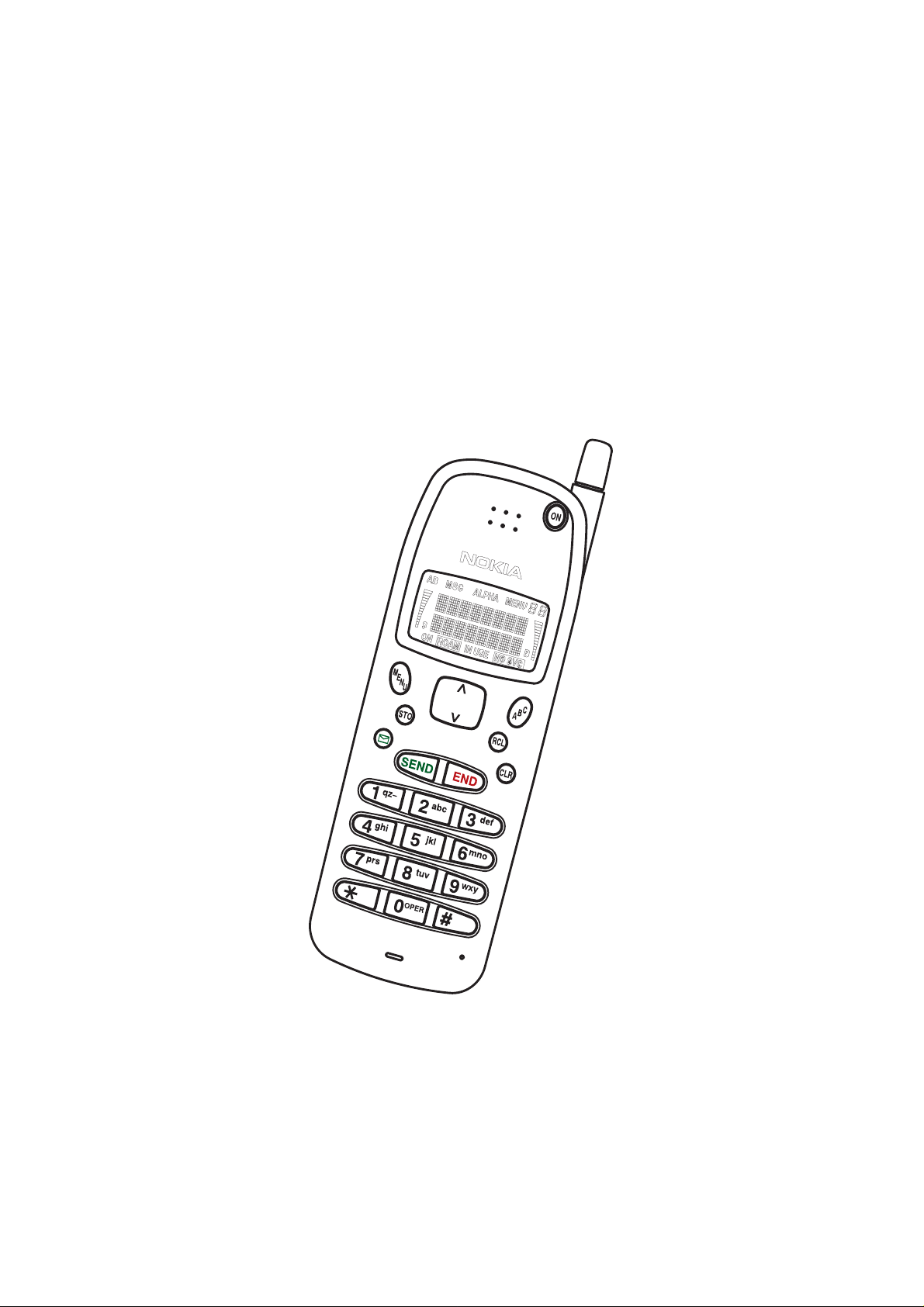
List of Keys
Figure 1 showing the keys can be found overleaf.
ON Press and hold to switch the phone on or off.
ABC Selects alpha mode/number mode; ie, press once to select
alpha mode (ie, to enter characters or display names), and
press again to select number mode.
MENU Selects menu mode.
or Scrolls the memory locations.
After pressing MENU, or scrolls the menus and displays
options.
RCL Recalls information from a memory location.
If the display is full, shows hidden digits.
STO Stores information in a memory location.
In a menu, confirms a setting.
Dials voicemail or favourite number.
CLR Deletes characters and clears display.
SEND Dials a number.
Pressing MENU SEND in a call can send DTMF data.
END Ends a call.
0 to 9
* and # Enter numbers and characters.
9 (for emergency calls), * and # are also used for one–touch
dialling.
* is also used for the special characters, ’+’, ’p’ and ’w’.
’+’ may be used as an international dialing prefix, and for
memory linking. ’+’, ’p’ and ’w’ are used for DTMF dialling.
On the side of the phone:
and Select earpiece volume.
Original, 12/95
Page 3–3
Page 17

THA–41S
After Sales
Quick Guide
Figure 1: THA–41S Transceiver
Technical Documentation
Page 3–4
Original, 12/95
Page 18

After Sales
THA–41S
Technical Documentation
Display Indicators
1
2
Quick Guide
11 10 9
8
7
5 643
1
AB Indicator Shows which network is in use:
A – System A only
B – System B only
AB – Both systems
Blank – Home area only
2
Signal Indicator Shows approximate received signal strength.
3
ON Indicator Shows the phone is switched on.
4
ROAM Indicator Shows which system the phone is using:
On – home system in a non–home area
Flashing – non–home system
Off – home system in the home area
5
IN USE Indicator Shows that a call is in progress.
6
NO SVC Indicator Shows that cellular service is not available.
7 Battery Indicator Shows approximate capacity remaining.
Scrolls when charging is in progress.
Flashes to show that battery is too hot or cold and
will not be charged.
If charging while phone is switched off, the indicator
bars disappear, but B remains on.
8
Number Shows menu or memory location selected.
9
MENU Indicator Shows that menu mode has been selected.
ALPHA Indicator Shows that alpha mode has been selected; letters
10
MSG Indicator Shows that a caller has left a message.
11
Original, 12/95
can be entered, and names can be displayed.
Page 3–5
Page 19

THA–41S
After Sales
Quick Guide
Technical Documentation
Getting Started
Switch on/off Press and hold the ON key.
Make a call Key in the number (include area code if
necessary). Press SEND key.
Answer a call Press any key except ON or the VOL-
UME keys.
End a call Press END key.
Clear digit Press CLR key.
Clear display Press and hold CLR key.
Last number redial Ensure display is clear, then press
SEND key.
Adjust volume Press or key.
Reading a message Messages are displayed in one of three
formats:
Voice Mail – the number of calls re-
ceived and ! is displayed if urgent.
Text – Up to 15 characters displayed.
Callers number – Press SEND to dial
and recall.
The Memory
Store a phone number Key in area code, number (and, when
alpha mode is selected, name if re-
quired).
Press STO key. Press STO key again to
store the number in the first empty mem-
ory location.
Speed dialling Enter the number of the memory loca-
tion containing the number to be dialled
(eg. 2).
Alternatively, press ABC key (to select
alpha mode), then enter the name
stored with the number to be dialled.
Press SEND key.
Scroll through memory Press RCL then * or # to scroll all used
memory locations in numerical order.
Scroll for a name Press ABC key (to select alpha mode).
Press key to display the name which
is first in alphabetical order, or press
key to display the name which is last.
Press or key to display other
stored names.
Page 3–6
Original, 12/95
Page 20

After Sales
THA–41S
Technical Documentation
Recall a specific memory location
Recall your own number Press RCL 99
Either: press RCL followed by the loca-
tion number (eg. for location 2, press
RCL 2)
or: enter a memory location number
then press RCL (eg. for location 1 press
1 RCL, or for location 12 press 1 2
RCL):
Quick Guide
The Menu Method
Enter menu Press MENU key.
Scroll Press or key.
Select function Press STO key.
Set option Press or key to scroll the options.
Press STO key to select option dis-
played.
Shortcut facility Press MENU key, then enter the number
of the menu function required (see table
below and overleaf).
The main menu features available are listed in the table below:
Menu Name Short Cut Description
LOCK PHONE MENU 0 (L) Locks/unlocks the phone.
SYSTEM SELECT MENU 1 Selects roaming mode
(system feature).
RINGING TYPE MENU 2 Selects the ringing tone
type.
CALL TIMERS MENU 3 Displays length of calls.
Resets the timers (S).
LIGHTS CONTROL MENU 4 Selects operation of dis-
play and keypad lights.
KEYPAD TONES MENU 5 Switches keypad tones
on/off.
RINGING VOLUME MENU 6 Selects volume of ringing
tone.
NAM SELECT MENU 7 Displays and selects cellu-
lar number/network.
AUTO ANSWER MENU 8 Sets automatic answer on/
off.
ACCESSORY MENU MENU 9 Controls accessories con-
nected to phone.
Original, 12/95
Page 3–7
Page 21

THA–41S
After Sales
Quick Guide
Menu Name Short Cut Description
CLEAR LAST CALL MENU 10 Sets the last–called
CHANGE LOCK CODE MENU 11 (S) Allows you to change lock
DATA MODE MENU 12 Selects data mode (in a
EMERGENCY 9 KEY MENU 13 (L) Sets 9 key on/off for one–
CALL BARRING MENU 14 (S) Sets call restrictions.
MEMORY LOCK MENU 15 (S) Sets memory access re-
ACTIVATE KEYGUARD MENU * or MENU 16 Locks/unlocks the keypad.
Technical Documentation
numbers to be cleared or
retained when phone is
switched off.
code.
call).
touch dialling of emergency calls.
strictions.
SEND DTMF MENU SEND or MENU 17 Sends DTMF tones (in a
call).
SID SCREEN MENU 18 (L) Selects SID to on/off.
MESSAGE ALARM MENU 19 Selects the audible alarm
used when you receive a
message.
MESSAGES MENU 20 Allows you to read or de-
lete a message.
NOTE: Menu 18 is available only if SID information
has been programmed into the selected NAM by your
dealer.
Table Notes:
(L) = requires entry of 4–digit lock code (default 1234)
(S) = requires entry of 5–digit security code (default 12345)
Page 3–8
Original, 12/95
Page 22

After Sales
THA–41S
Technical Documentation
Quick Guide
Battery Information
Charging Times
After the first use, the charging times depend on the type of battery fitted,
and charger used; approximate times are shown below.
Battery Type
Charger Type BTH–8S/L BTH–8SM BTH–8H BTH–8HM
Travel Charger
(ACH–3U/E/P)
Fast Travel Charger
ACH–4U/E/P
Cigarette Lighter
Charger LCH–2
Standby and Talk Times
1.5 hrs 2 hrs 10 m 5 hrs 5.5 hrs
40 mins 60 mins 70 mins 100 mins
Approximate standby and talk times, for fully–charged batteries:
Battery Type Standby Time Talk Time
Light NiCd 300mAh (BTH–8L)* 9 hours 40 minutes
Standard NiCd 380mAh (BTH–8S) 10 hours 50 minutes
Standard NiMh 550mAh (BTH–8SM) 15 hours 70 minutes
Extended NiCd 800mAh (BTH–8H) 26 hours 110 minutes
Extended NiMh 1100mAh (BTH–8HM) 32 hours 150 minutes
* subject to availability
NOTE: You will obtain the standby time specified or
combination. Thus (for BTH–8S), 10 hours standby time or
time is approximately equivalent to 5.5 hours standby time and 25 minutes
talk time.
the talk time specified, or a
50 minutes talk
Original, 12/95
Page 3–9
Page 23

THA–41S
After Sales
Quick Guide
Technical Documentation
[This page intentionally left blank]
Page 3–10
Original, 12/95
Page 24

After Sales
Technical Documentation
Appendix Structure 1–3. . . . . . . . . . . . . . . . . . . . . . . . . . . . . . . . . . . . . . . . . . . . . . .
Company Policy 1–3. . . . . . . . . . . . . . . . . . . . . . . . . . . . . . . . . . . . . . . . . . . . . . .
Warnings and Cautions 1–4. . . . . . . . . . . . . . . . . . . . . . . . . . . . . . . . . . . . . . . . . . .
Warnings: 1–4. . . . . . . . . . . . . . . . . . . . . . . . . . . . . . . . . . . . . . . . . . . . . . . . . . . .
Cautions: 1–5. . . . . . . . . . . . . . . . . . . . . . . . . . . . . . . . . . . . . . . . . . . . . . . . . . . . .
THA–4
4
Original 05/95
 Loading...