

Page 1
After Sales Technical Documentation
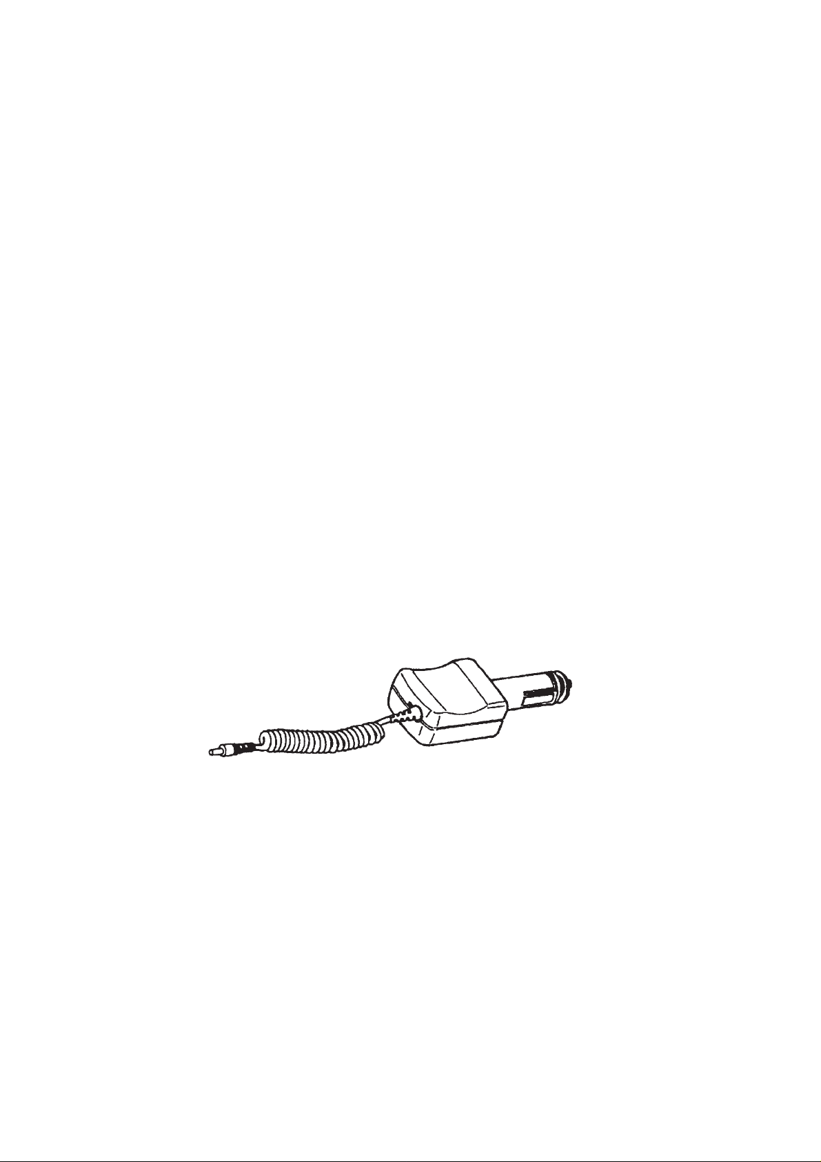
CIGARETTE LIGHTER
CHARGER
LCH–2
Original, 05/94
NMP Part No. 0275007
Page 2
Cigarette Lighter Charger LCH–2
AMENDMENT RECORD SHEET
After Sales
Technical Documentation
Amendment
Number
Date Inserted By Comments
Original, 05/94Page 2
Page 3

After Sales
Technical Documentation
Cigarette Lighter Charger LCH–2
CIGARETTE LIGHTER CHARGER LCH–2
CONTENTS
Page No
Introduction 5
General 5
Modes of Operation 5
Charge States and Charge Control 5
Charge Indication 5
Electrical Specifications 6
Functional Description 6
Circuit Description 6
General 6
Converter 6
Oscillator 6
Pulse–width Control 7
Current Limiting 7
Assembly Parts 9
List of Figures
Figure 1: Block Diagram 8
Figure 2: Component Layout Diagram 8
Figure 3: Exploded View 9
Figure 4: Circuit Diagram 11
Original, 05/94 Page 3
Page 4

Cigarette Lighter Charger LCH–2
After Sales
Technical Documentation
[This page intentionally left blank]
Original, 05/94Page 4
Page 5

After Sales
Technical Documentation
Introduction
General
The LCH–2 Cigarette Lighter Charger is used for charging the battery of
the phone from a 12 or 24 V cigarette lighter socket of a motor vehicle.
The charger is provided with LED charging indication.
Modes of Operation
Charge States and Charge Control
The LCH–2 cigarette lighter charger is used for charging a handportable
phone from a car battery. A constant–current or constant–voltage output is
provided depending on the operating state of the phone.
Charge current is supplied through a series switch transistor located in the
phone. When the transistor is on the charger supplies a constant current
to the phone. The phone is then in the rapid charge mode.
Cigarette Lighter Charger LCH–2
When the transistor is off no current is supplied to the phone and the
charger is in the constant–voltage mode.
Once fully charged in the rapid charge mode, the battery is kept full by
means of pulsed charging. Current is switched on and off at a variable
duty cycle and a frequency of a few Hz.
Charge Indication
Charger states are indicated with a dual–colour LED located in the
cigarette lighter charger unit.
In addition, the phone LCD contains a three–bar battery status display,
operative when power for the phone is on.
”Charging sequence active” (state A) is indicated by the bars being lit
sequentially, starting from the bottom one.
”Battery full” (state B) is indicated by all three bars steadily lit.
Phone Operating Status LED Display
Cigarette Lighter Charger connected to vechile, phone disconnected
Green
Phone connected to charger,
charging disabled due to battery
temperature
Rapid charge Red state A
Battery full –> trickle charge Green state B
Calling state Green or Red * state A
Original, 05/94 Page 5
Green state A
Page 6

Cigarette Lighter Charger LCH–2
* Battery capacity is maintained during a phone call by occasional
rapid charge cycles. Consequently, the LED can be indicating either
red or green.
Electrical Specifications
Operating input voltage: 9 to 32 V d.c.
Input current without phone: < 60 mA
Max. input current: 1.8 A
Output voltage:–
constant voltage: 12.5 1 V/0...400 mA
constant current: 800 70 mA/5.0...10 V
Functional Description
After Sales
Technical Documentation
Circuit Description
General
The charger module consists of a switched–mode converter and a
bicolour indicator LED. The converter is of the step up/down type, i.e. the
output voltage can be lower or higher than the input voltage.
Converter
Converter input current is received via filter capacitor C101. The converter
consists of coils L110, L112, FET switch V112, d.c. level shifting capacitor
C111 and Schottky diode V113. Output energy is stored and filtered by
C112, L111 and C113.
In series with converter coil L112 is resistor R116, used for measuring the
output current. When operating, the converter generates a negative
voltage drop (as compared to ground level) at R116, directly proportional
to output current.
Converter control is by N110, a quad comparator with open–collector
output. The 5 V reference supply is generated by regulator N100.
Oscillator
The converter operates at a fixed frequency of 300 kHz, produced by
oscillator N110A. A suitable operating voltage for the comparator positive
input is set by resistor divider R112/R114. Positive feedback from the
comparator output is supplied by R111 in parallel with C104. When the
comparator output is high C110 is charged through R110 and R113 until
the voltage at the negative input exceeds the positive input. At that instant
the comparator output turns low and C110 is discharged via R113.
Original, 05/94Page 6
Page 7

After Sales
Technical Documentation
Pulse–width Control
Pulse width is controlled by comparator N110B, where the sawtooth
voltage from the oscillator is compared to a d.c. control voltage. Max.
control voltage is set by resistor divider R121/R120 to make sure that
pulse width cannot reach 100 % under any conditions as this would mean
short–circuiting VB to GND via V112.
When the control voltage drops, so do the pulse width and the converter
output current. The control voltage can be pulled down by output current
comparator N110C, output voltage comparator N110D, or by the ”error”
output pin of a reference regulator N100.
Current Limiting
Output current is measured with series resistor R116 connected between
L112 and GND. When the converter operates with the output loaded it
generates a negative voltage drop (as compared to GND) over this
resistor.
Cigarette Lighter Charger LCH–2
The voltage drop is added to the positive reference value set by R122 and
R123 and used as the current comparator positive input. The current
comparator compares the level of this input to zero (ground) level. When
the current reaches the limit, voltage at the positive input falls to zero and
the comparator output goes down, limiting the duty cycle. The value of the
current limit is set by resistor divider R122, R123. A negative feedback for
stabilizing the comparator is produced with R124.
Original, 05/94 Page 7
Page 8

Cigarette Lighter Charger LCH–2
Figure 1: Block Diagram
After Sales
Technical Documentation
Figure 2: Component Layout Diagram
Original, 05/94Page 8
Page 9

After Sales
Technical Documentation
Figure 3: Exploded View
Cigarette Lighter Charger LCH–2
Assembly Parts
ITEM Q’TY CODE DESCRIPTION VALUE, TYPE
1 9450050 Cover 1D 21289
2 9450051 Bottom 1D 21288
3 9450052 Head–screw 3D 21287
4 9500005 Head–pin 4D 21390
5 6400056 Connector spring 4D 21391
6 3 6154430 PT–screw 25 x 8 WN–1442
7 9370095 Type label 4D 21487
8 7100408 Spiral cable 3D 21247
9 5112050 Fuse 3.15 A/250 V 6.3 x 32 mm
10 9510050 Bottom shield 4D 21395
11 9480023 Separating film 4D 21793
12 Shield
C1 0200044 AL4 module
Original, 05/94 Page 9
Page 10

Cigarette Lighter Charger LCH–2
After Sales
Technical Documentation
[This page intentionally left blank]
Original, 05/94Page 10
 Loading...