

Page 1
After Sales Technical Documentation
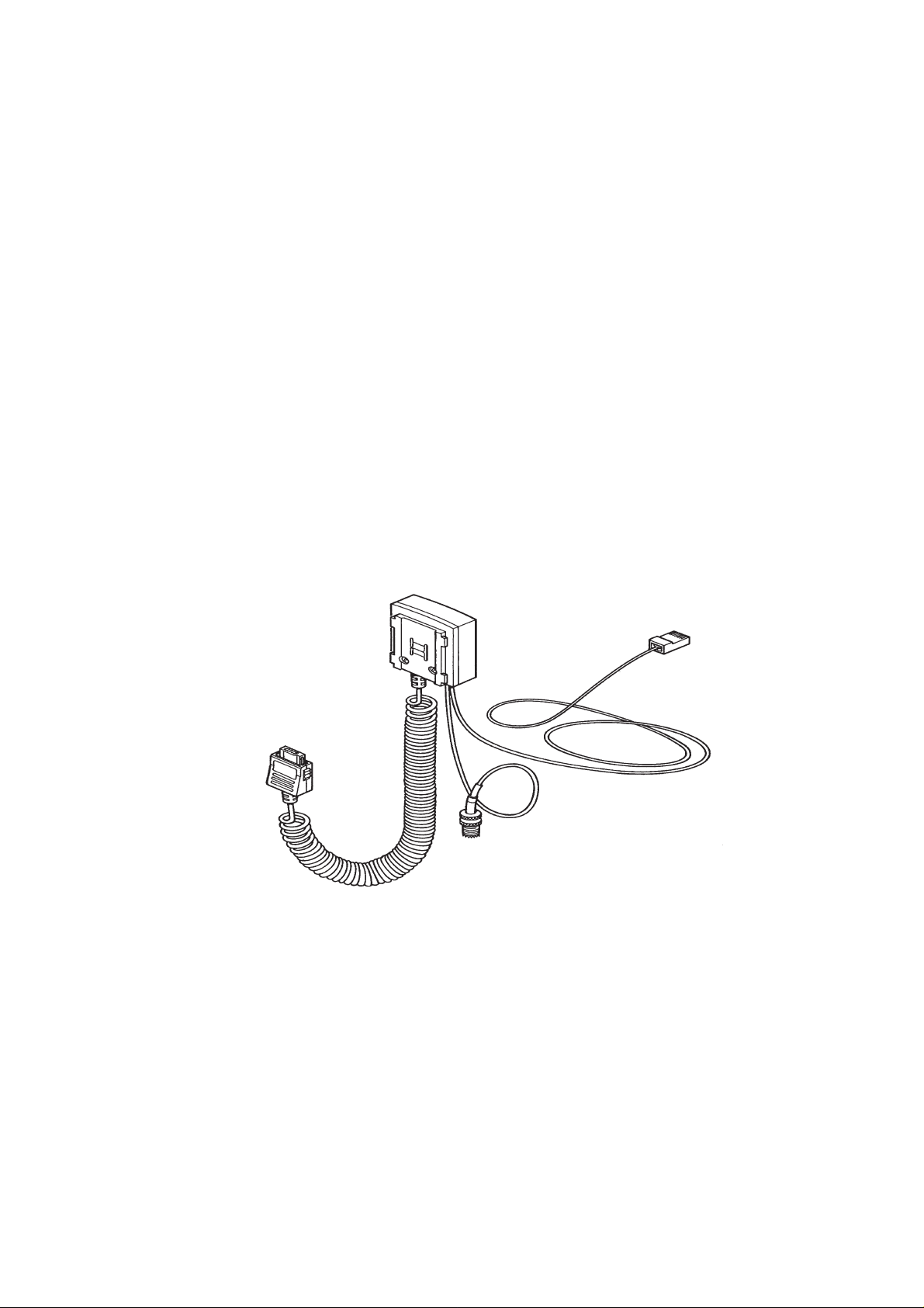
CABLE JUNCTION BOX
JBH–1
Original, 05/94
NMP Part No. 0275009
Page 2
Cable Junction Box JBH–1
AMENDMENT RECORD SHEET
After Sales
Technical Documentation
Amendment
Number
Date Inserted By Comments
Original, 05/94Page 2
Page 3

After Sales
Technical Documentation
Cable Junction Box JBH–1
CABLE JUNCTION BOX JBH–1
CONTENTS
Page No
Introduction 5
Technical Summary 5
List of Modules 5
Technical Specifications 6
Modes of Operation 6
Phone Located Inside MBH–9 Holder 6
Phone Located Outside MBH–9 Holder 6
Extreme Conditions 6
Maximum Ratings 6
Control Signals 6
AC Characteristics 6
External Signals and Connections 6
HFJ Cable + Connector (Connector A) 7
Phone Connector X001 7
Coax Coil Cord Mini RF Connector 8
Mechanical Characteristics 8
Functional Description 8
Schematic 8
List of Figures
Figure 1: Schematic 9
Original, 05/94 Page 3
Page 4

Cable Junction Box JBH–1
After Sales
Technical Documentation
[This page intentionally left blank]
Original, 05/94Page 4
Page 5

After Sales
Technical Documentation
Cable Junction Box JBH–1
Introduction
The JBH–1 Cable Junction Box has been designed for use specifically with
the MBH–9 In–car Holder (to which it interfaces) and the existing Fixed Car
Kit (based on the HFJ–2 Handsfree Junction Box )
The JBH–1 enables the signals from the Coax Coil Cord, which plugs into the
Phone, to be split into audio and RF for connection to the HFJ–2 Handsfree
Junction Box (via the SCE–2 Front Mount Cable if the Booster is fitted) and
the Vehicle Antenna (via the XRH–1 RF extension Cable if the Booster is
fitted).
The JBH–1 Cable Junction Box enables the phone to access all the normal
features of the existing HFJ–2 Handsfree Junction Box, with the exception of
an External Audio Handset which is NOT specified for use with this phone.
Technical Summary
The JBH–1 Cable Junction Box is a passive device and therefore connects
directly between the phone and HFJ–2/SCE–2 and the Vehicle
Antenna/XRH–1. However, there is a PCB (DC8) contained within the
Accessory Connector upon which there is mounted a Reed Switch and a zero
Ohm resistor to act as a link, since the same DCX2 PCB is used in another
application. The Reed Switch is “pulled” by a Magnet located in the MBH–9
In–car Holder; its function is to signal to the phone whether it is located in the
holder or not. If the phone is located in the holder then it will operate in
“Handsfree” mode, if not then it will operate in “Handset” mode. The Reed
Switch is of the “Normally Open” type ie. it is closed by the MBH–9 magnet.
List of Modules
Name of Module Type Code Material Code Notes
Cable Junction Box JBH–1 0630008 Complete
Assembled Unit
Connector PCB
Module
HFJ Cable +
Connectors
DC8 0200377 Fits inside
accessory
connector
4C22080 7100422 NMP Cable used
on MCH–3
Assembly Parts MJBH1 0260336
Original, 05/94 Page 5
Page 6

Cable Junction Box JBH–1
Technical Specifications
Modes of Operation
Phone Located Inside MBH–9 Holder
Phone operates in “Handsfree” mode and connected to external antenna.
Phone is charged by HFJ–2 through JBH–1.
Phone Located Outside MBH–9 Holder
Phone operates in “Handset” mode and connected to external antenna.
Phone is charged by HFJ–2 through JBH–1.
Extreme Conditions
After Sales
Technical Documentation
Storage Temperature:– –40°C + 85°C
Operating Temperature:– –30°C + 60°C
Absolute Maximum Current/pin:– 1 A
Maximum Ratings
Maximum Voltage at any pin to ground:– 50 V dc
Control Signals
Refer to External Signals and Connections section.
AC Characteristics
Not applicable since JBH–1 is a passive unit.
External Signals and Connections
A list of connectors is shown in the following table.
Connector Name Code Notes Specifications/
Ratings
HFJ–2 Connector Connector A 8 Pole
Phone Connector
(see X001)
RF signal from
phone to
Vehicle/Booster
antenna
Mini RF Connector
X001 10 Pole– mounted
on DC8 Module
Coax Coil Cord
2 Pole
PCB
Original, 05/94Page 6
Page 7

After Sales
Technical Documentation
HFJ Cable + Connector (Connector A)
Signal Name Pin/Con Notes
XEXAUD/TXI 1 Booster Control. Active Low
DGND/PGND 2 Ground for Charger
M2BUS 3 Serial MBUS data between
VC 4 Supply Voltage/ charging current
HOOK 5 Handset Hook Indication
AGND/SGND 6 Audio Ground
XMIC/HFJCONN 7 Audio signal from HFJ–2, input to
XEAR/HFJPWR 8 Audio signal from phone to
Cable Junction Box JBH–1
phone, accessories and HFJ–2
for phone
phone
HFJ–2
Phone Connector X001
Signal Name Pin/Con Notes
VC 1 Supply Voltage/charging current
XEAUD 2 RF Booster PWM Control
HOOK 3 Indicates to the phone whether in
XEAR/HFJPWR 4 Audio signal from phone to
DGND 5 Digital Ground
VC 6 Supply Voltage/charging current
M2BUS 7 MBUS data between the phone,
AGND 8 Audio Ground
XMIC/HFJCONN 9 Audio signal from HFJ–2, input to
for phone
or out of MBH–9 In–car holder.
Line will be ”Low” when phone is
inside MBH–9, ”High” when out.
HFJ–2.
for phone
Accessories and HFJ–2.
phone.
DGND 10 Digital Ground
Original, 05/94 Page 7
Page 8

Cable Junction Box JBH–1
Coax Coil Cord Mini RF Connector
Signal Name Pin/Conn Notes
RF Conductor Centre Pin RF Signal from phone to
RF Ground Shield RF Signal Ground
Mechanical Characteristics
After Sales
Technical Documentation
external Antenna
Connection
Unit Dimensions
(mm)
(WxHxD)
JBH–1 49x22x54 150 Antenna:0.30
Weight
(g)
Cable Length
(metres)
0.015
Audio:
1.450.05
Material/
Colour
JBH–1
Housings:
CYCOLOY C
1000HF–96127
Colour: Warm
Black
Functional Description
The DC8 PCB Module, located inside the accessory connector, contains a
Reed Switch, to signal to the phone whether or not it is located in the MBH–9
In–Car Holder; a connector (X001) which plugs into the bottom of the phone;
and a zero Ohm resistor which acts as a link, since the DC8 PCB (DCX2) is
used in another application.
The RF signal from the phone to the External Antenna or Booster is achieved
using a direct connection between the X001 Connector and the mini UHF
connector via the Coax Coil Cord. The mini UHF Connector mates with the
External Antenna Connector or the Booster XRH–1 Cable.
Schematic
The top–level schematic for JBH–1 is shown overleaf.
Original, 05/94Page 8
Page 9

After Sales
Technical Documentation
Figure 1: Schematic
Cable Junction Box JBH–1
Mini UHF
Connector
CONNECTOR A X001
X002_4 Vc
X002_1 XEXAUD/
TXI
X002_5 HOOK
X002_8 XEAR
X002_2 DGND/
PGND
X002_3 MBUS
X002_6 AGND/
SGND
X002_7 XMIC
CONNECTOR B
BROWN
ORANGE
VIOLET
GREEN
YELLOW
RED
BLACK
BLUE
W001
4
4
1
5
8
2
3
6
7
WHITE
1
GREEN
5
BLUE
8
YELLOW
2
BROWN
3
RED
6
BLACK
7
ORANGE
E1
E2
E3
E4
E8
E5
E6
E7
Mini RF
Connector
S1
R1
0R0
R2
N/F
R3
N/F
X1–1 VC
X1–2 XEXAUD
X1–3 HOOK
X1–4 XEAR
X1–5 DGND
X1–6 VC
X1–7 MBUS
X1–8 AGND
X1–9 XMIC
HFJ CABLE
(7100422)
W001
(970097)
X1–10 DGND
DC8 MODULE
(0200377)
Original, 05/94 Page 9
Page 10

Cable Junction Box JBH–1
After Sales
Technical Documentation
[This page intentionally left blank]
Original, 05/94Page 10
 Loading...