

Page 1

Programmes After Market Services
TME-1 Series Transceivers
Disassembly and Troubleshooting
Issue 1 ãNokia Mobile Phones Ltd.
Page 2
TME-1
Disassembly and Troubleshooting PAMS Technical Documentation
Table of Contents
Page No
Introduction.................................................................................................................... 3
Disassembly, TME-1 ..................................................................................................... 4
Disassembly, DTX-1 ...................................................................................................5
Troubleshooting ............................................................................................................. 6
General .........................................................................................................................6
Visual overlook ............................................................................................................6
Testing with WinTesla service software ......................................................................7
Connections in LA circuit tests and in DTMF Rx/Tx tests....................................... 7
WinTesla tests ........................................................................................................... 8
Testing of Line adapter circuits ..............................................................................8
Hook state indicator ................................................................................................8
DTMF receiving and transmitting .......................................................................10
Ringing Voltage Indicator ....................................................................................11
Connections in audio codec tests ............................................................................ 12
Audio codec test ....................................................................................................12
UI LEDs .................................................................................................................. 15
AM self test ............................................................................................................. 16
Table of Figures
Page No
Fig 1 TME-1 disassembly....................................................................................................4
Fig 2 DTX-1 Disassembly ...................................................................................................5
Fig 3 UI light indicators.......................................................................................................6
Fig 4 Line Adapter circuit test window ...............................................................................8
Fig 5 Hook on/off test window 1 ........................................................................................8
Fig 6 Hook on/off test window 2 ........................................................................................9
Fig 7 DTMF test window.....................................................................................................10
Fig 8 Audio&Line Test window..........................................................................................11
Fig 9 Audio Codec Test set-up ............................................................................................12
Fig 10 Audio codec Test window ........................................................................................13
Fig 11 ET Call Test window................................................................................................13
Fig 12 Call Test dialog box..................................................................................................14
Fig 13 UI Led Test window.................................................................................................15
Fig 14 LEDs Test dialog box...............................................................................................15
Fig 15 AM Self Test window ..............................................................................................16
Fig 16 AM Self Test dialog box ..........................................................................................16
Page 2 ãNokia Mobile Phones Ltd. Issue 1
Page 3

TME-1
PAMS Technical Documentation Disassembly and Troubleshooting
Introduction
The purpose of this document is to help in hardware troubleshooting of the Nokia 22 PBX
Connectivity Terminal.
TME-1 includes the RPM-3 , troubleshooting of which is described in the RPM-1 manual.
DTX-1 module is not designed to be repaired except the Application Interface Connector.
Issue 1 ãNokia Mobile Phones Ltd. Page 3
Page 4
TME-1
Disassembly and Troubleshooting PAMS Technical Documentation
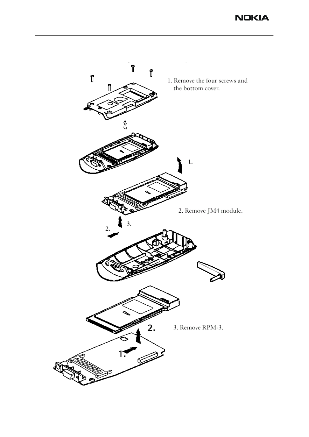
Disassembly, TME-1
Figure 1: TME-1 disassembly
Page 4 ãNokia Mobile Phones Ltd. Issue 1
Page 5
TME-1
PAMS Technical Documentation Disassembly and Troubleshooting
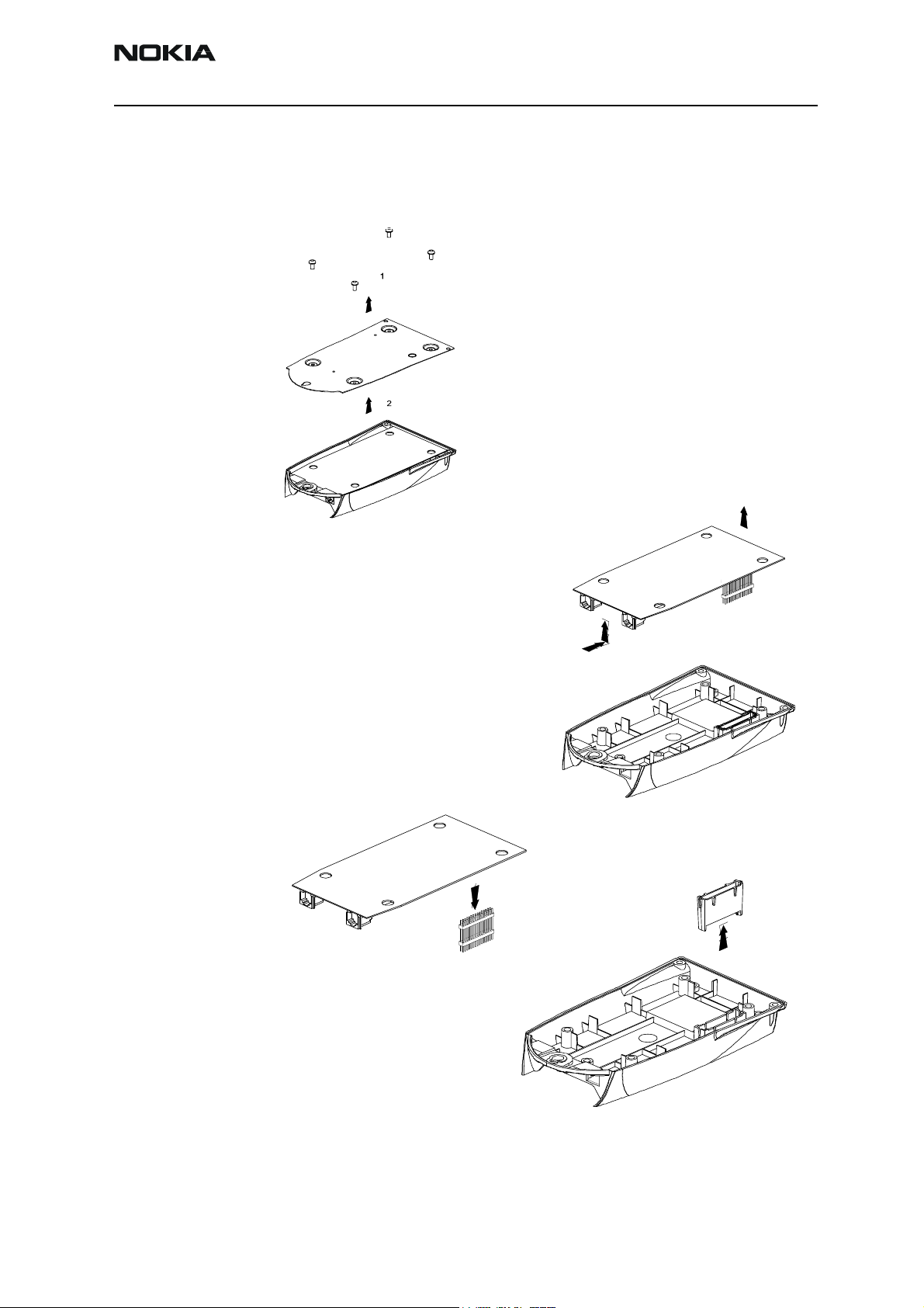
Disassembly, DTX-1
Figure 2: DTX-1 Disassembly
1. Remove the four screws and
the bottom plate.
2. Remove JP4 module.
3. Remove the pin header.
4. Remove the pin header
cover.
Issue 1 ãNokia Mobile Phones Ltd. Page 5
Page 6

TME-1
Disassembly and Troubleshooting PAMS Technical Documentation
Troubleshooting
General
The purpose of this document is to help the service point to solve which part of the radio
is faulty. The service policy with the Nokia22 connectivity terminal is, that only the RPM-
3 will be repaired. If either the PC-board of the DTX-1 or the TME-1 is faulty, the faulty
PC-board will be replaced with a new one.
Visual overlook
The UI-Light indicators are split into two parts:
•AM LIs
•ET LIs
Figure 3: UI light indicators
Light indicators 1&2 are used to tell in which mode the line adapter is at the moment.
Light indicators 3,4 and 5 are used to tell the state of the embedded GSM terminal. At
least one Light indicator from both parts should be on or blinking. If e.g. both Light indi-
cator 1 and Light indicator 2 are off, the fault most probably is in the application mod-
ule.
Page 6 ãNokia Mobile Phones Ltd. Issue 1
Page 7

TME-1
PAMS Technical Documentation Disassembly and Troubleshooting
Testing with WinTesla service software
Connections in LA circuit tests and in DTMF Rx/Tx tests
Connect the FLA-26 adapter between the GSM terminal and the PBX application module.
Connect the DKT-6A cable from the FLA-7 to the FLA-26. Connect the SCS-24 Line
Adapter test cable between the Trunk and Extension connectors on the PBX application
module.
NOTE: Do not in any circumstances connect the PCS-1 cable in the TME-1 socket !
Polarity of the TME-1 is reversed !
Test equipment set-up
WinTesla tests
Testing of Line adapter circuits
Choose Te
sting -> Audio -> Line Adapter...
Issue 1 ãNokia Mobile Phones Ltd. Page 7
Page 8

TME-1
Disassembly and Troubleshooting PAMS Technical Documentation
Figure 4: Line Adapter circuit test window
Hook state indicator
Check that the Hook off/on indicator state will change when you change the hook state.
If not, the DTX-1 is faulty.
Figure 5: Hook on/off test window 1
indicators
Page 8 ãNokia Mobile Phones Ltd. Issue 1
Page 9

TME-1
PAMS Technical Documentation Disassembly and Troubleshooting
Figure 6: Hook on/off test window 2
indicators
Issue 1 ãNokia Mobile Phones Ltd. Page 9
Page 10

TME-1
Disassembly and Troubleshooting PAMS Technical Documentation
DTMF receiving and transmitting
Write some numbers to the DTMF string field. Change the hook off state to 'Off',
press the S
the 'Received string:' row, that all numbers that you just selected were transmitted.
end button and listen from the earpiece the DTMF tones. Check also from
Figure 7: DTMF test window
DTMF String field
Received String field
Page 10 ãNokia Mobile Phones Ltd. Issue 1
Page 11

TME-1
PAMS Technical Documentation Disassembly and Troubleshooting
Ringing Voltage Indicator
Change the 'Trunk line state' selection to the Ring position.
Figure 8: Audio&Line Test window
Ring position
Ring indicator state
Check that also the state of the Ring indicator changes (it might take few seconds). If
the indicator will not change it's position, change the 'Trunk line state' choice to it's
original setting, and try again couple of times. If the indicator will not change it's posi-
tion, the DTX-1 is probably broken.
Issue 1 ãNokia Mobile Phones Ltd. Page 11
Page 12

TME-1
Disassembly and Troubleshooting PAMS Technical Documentation
Connections in audio codec tests
Connect the FLA-26 adapter between the GSM terminal and the PBX application module.
Connect the DKT-6A cable from the FLA-7 to the FLA-26.
Connect a landline telephone set in the Trunk socket of the PBX application module.
NOTE: Do not in any circumstances connect the PCS-1 cable in the TME-1 socket !
Polarity of the TME-1 is reversed !
Figure 9: Audio Codec Test set-up
Audio codec test
Activate the HF-state from the land-line telephone, or take the earpiece to listen the sig-
nal tones. From the Tone generator field you can select different tones to be listened.
Page 12 ãNokia Mobile Phones Ltd. Issue 1
Page 13

TME-1
PAMS Technical Documentation Disassembly and Troubleshooting
Figure 10: Audio codec Test window
If you can not hear these tones, the audio codec is probably faulty.
Try to make also a test call, both with the land line telephone and with the aid of the
WinTesla service software.
Figure 11: ET Call Test window
Issue 1 ãNokia Mobile Phones Ltd. Page 13
Page 14

TME-1
Disassembly and Troubleshooting PAMS Technical Documentation
Figure 12: Call Test dialog box
Dial a phone number to be called to a Dialogue box and press Call.
Page 14 ãNokia Mobile Phones Ltd. Issue 1
Page 15

TME-1
PAMS Technical Documentation Disassembly and Troubleshooting
UI LEDs
To test all UI-LEDs, select Testing -> Leds…
Figure 13: UI Led Test window
Figure 14: LEDs Test dialog box
Check from the EGSMT that all Leds behaves like you select from the Leds Test window.
From the behaviour of the Leds can be deduced whether the fault is in the Led(s) or in
the control circuits.
Issue 1 ãNokia Mobile Phones Ltd. Page 15
Page 16

TME-1
Disassembly and Troubleshooting PAMS Technical Documentation
AM self test
With this option it can be checked whether any of AM parameters is missing.
Figure 15: AM Self Test window
Figure 16: AM Self Test dialog box
Dialogue box like the one above should appear to indicate that all parameters are ok in
EEPROM.
Page 16 ãNokia Mobile Phones Ltd. Issue 1
 Loading...