

Page 1

Programmes After Market Services
TME-1 Series Transceivers
Tuning and Flashing Instructions
Issue 1 ãNokia Mobile Phones Ltd.
Page 2

TME-1
Tuning and Flashing Instructions PAMS Technical Documentation
Table of Contents
Page No
RF Tuning Instructions .................................................................................................. 3
General .........................................................................................................................3
Required Equipment ....................................................................................................3
Equipment Setup ..........................................................................................................3
Tuning Steps .................................................................................................................. 5
RX Calibration (AGC + AFC) for both bands ............................................................5
I/Q Modulator Amplitude Balance and Phase Shift Tuning ........................................7
Tuning of Transmitter Power Levels .........................................................................10
TME-1 SW Upgrade (flashing).................................................................................... 13
General .......................................................................................................................13
Connections when flashing TME-1......................................................................... 13
Connections when flashing DTX-1......................................................................... 13
Wintesla settings ..................................................................................................... 13
Configuring FPS-4 .................................................................................................. 14
Startup of WinTesla ..................................................................................................... 15
Getting started ............................................................................................................15
Flashing ......................................................................................................................15
Flashing TME-1 .........................................................................................................18
Restore Country specific settings ..............................................................................20
List Of Figures
Page No
Fig 1 Equipment Setup for RF Tuning the TME-1.............................................................4
Fig 2 Spectrum analyzer display..........................................................................................7
Fig 3 Select RPM-3 to flash the terminal module ..............................................................15
Fig 4 Select DTX-1 to flash the application module ..........................................................15
Fig 5 Market Area selection.................................................................................................16
Fig 6 MCU Image file selection ..........................................................................................16
Fig 7 Flashing ......................................................................................................................17
Fig 8 Dialog box. .................................................................................................................18
Fig 9 Restoring default user settings....................................................................................18
Fig 10 Dialog Box................................................................................................................19
Fig 11 Flash Phone Dialog box............................................................................................19
Page 2 ãNokia Mobile Phones Ltd. Issue 1
Page 3

TME-1
PAMS Technical Documentation Tuning and Flashing Instructions
RF Tuning Instructions
General
All tuning operations of the TME-1 are carried out using the WinTesla ser vice software.WinTesla interfaces with TME-1 via the FLA-26 service adapter.
For tuning the TME-1, use the same setup as for flashing the unit.
The tuning values of the phone are stored on the non-volatile memory of the RPM-3
GSM transceiver.. The contents of this memory can be read by the service software and
saved as a file. The program also enables writing the default tuning pa rameters, in which
case all tuning steps should be carried out.
During tuning, proceed as follows:
• Take care not to damage sensitive measuring instruments with exces sive RF
power. A spectrum analyzer may require an attenuator. TME-1 maximum output power may exceed 33 dBm (2 W) in GSM 900 band and 30 dBm (1 W) in
GSM1800 band.
• Carry out all tuning steps in the shortest possible time to avoid exces sive
heating of RF units.
• Perform all tuning steps in the order presented.
• Never try to mask a fault by tuning it out!
Required Equipment
• PC/AT computer with WinTesla service software; see separate section for
instructions on installation and use.
• Service accessories; see equipment setup lists.
• GSM radio telephone test station or separate measuring equipment as follows:
- RF generator
- pulse power meter
- spectrum analyzer
- attenuator
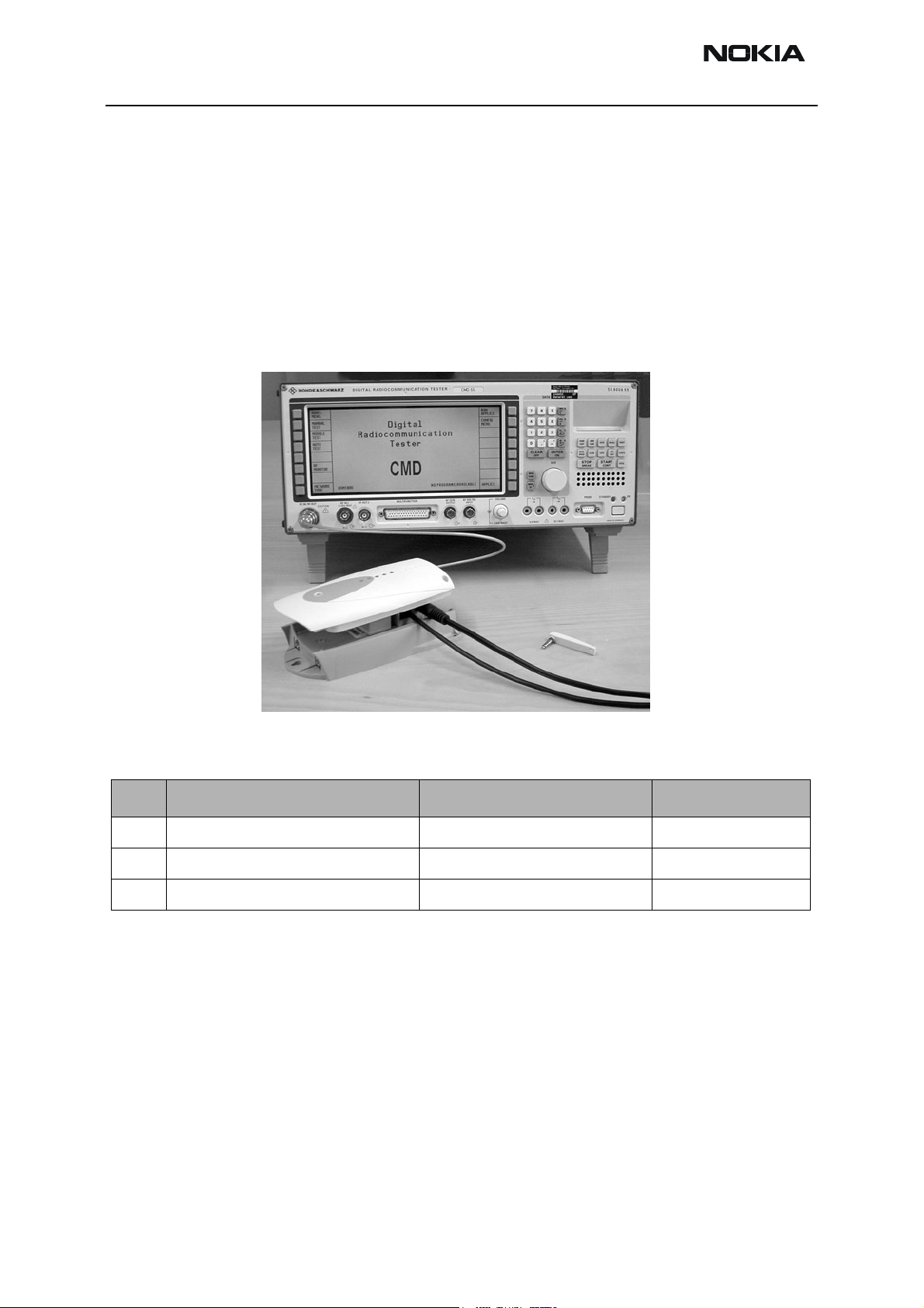
Equipment Setup
Caution: Make sure that you have switched off the PC and the printer before making connections !
Issue 1 ãNokia Mobile Phones Ltd. Page 3
Page 4
TME-1
Tuning and Flashing Instructions PAMS Technical Documentation
Caution: Do not connect the PKD-1 key to the serial port. You may damage your
PKD-1 !
Attach the protection key PKD-1 to parallel port one (25-pin female D-connector) of the
PC. When connecting the PKD-1 to the parallel port be sure that you insert the PC end of
the PKD-1 to the PC (male side). If you use a printer on parallel port one, place the PKD1 between the PC and your printer cable.
Next see the following lists for correct equipment.
Figure 1: Equipment Setup for RF Tuning the TME-1
:
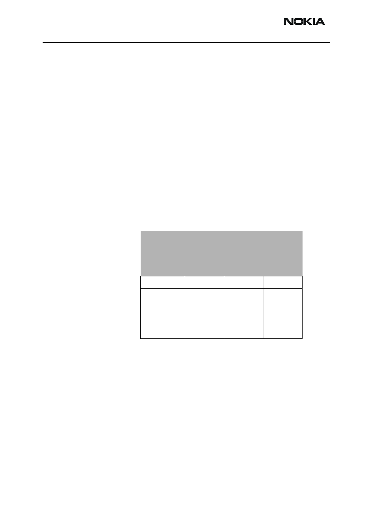
Table 1: List of service tools
Item Service accessory Type Code
1 Service adapter FLA-26 0770312
2 Service cable DKT-6A 0730213
3 Service RF cable Service RF cable XRP-3 0730206
Power supply for FLA-26:
Laboratory power supply 3A/12V (adjustable)
Power Supply Cable PCS-1
• 1. Install the FLA-26 adapter between the TME-1 and DTX-1.
• 2. Connect the FLA-26 to the FLA-7 with the DKT-6A cable.
• 3. Connect the PCS-1 power cable from the FLA-7 to the FLA-26.
Page 4 ãNokia Mobile Phones Ltd. Issue 1
Page 5

TME-1
PAMS Technical Documentation Tuning and Flashing Instructions
• 4. Pull out the TME-1 antenna
• 5. Connect the XRP-3 RF cable in the TME-1antenna socket for measurments.
NOTE! DO NOT IN ANY CIRCUMSTANCE CONNECT THE PCS-1 CABLE IN THE TME-1
SOCKET!
Tuning Steps
RX Calibration (AGC + AFC) for both bands
Reference values for the received signal strength meter are program tuned.
RSSI reference signal level programming:
• Select Product -> Band -> GSM
• Select Tuning -> RX Calibration
• Connect RF generator to TME-1 antenna conn at 947.067710 MHz.
• Adjust signal generator level to -55 dBm + cable attenuation.
• Press OK button
• Adjust signal generator level to -80 dBm + cable attenuation.
• Press OK button.
Service software reports:
A Table of AFC Parameters:
AFC INIT Value
AFC Slope
PSW Slope
A Table for AGC Calibration:
AGC in 3 db steps 0...57 dB
DAC and voltage reading for each gain value
• Press SAVE button
• Select Product -> Band -> PCN
Issue 1 ãNokia Mobile Phones Ltd. Page 5
Page 6

TME-1
Tuning and Flashing Instructions PAMS Technical Documentation
• Select Tuning -> RX Calibration
• Adjust signal generator level to -55 dBm + cable attenuation.
• Press OK button
• Adjust signal generator level to -80 dBm + cable attenuation.
• Press OK button.
Service software reports:
A Table of AFC Parameters:
AFC INIT Value
AFC Slope
PSW Slope
A Table for AGC Calibration:
AGC in 3 db steps 0...57 dB
DAC and voltage reading for each gain value
• Press SAVE button
Page 6 ãNokia Mobile Phones Ltd. Issue 1
Page 7

TME-1
A
PAMS Technical Documentation Tuning and Flashing Instructions
I/Q Modulator Amplitude Balance and Phase Shift Tuning
The purpose of this tuning operation is to adjust the I/Q modulator d.c. off sets and the I/
Q modulator amplitude balance and phase shift.
I/Q modulator d.c. offsets, amplitude balance and phase shift tuning:
• Select Product -> Band -> GSM
• Select Tuning -> TX I/Q...
• Select I/Q tuning values from PC's memory, phone's EEPROM or fac tory
default values.
• Connect spectrum analyzer (with attenuator if needed) to TME-1 an tenna
connector.
• Check that TX power level is level 10, channel is 60 and TX data type is
Cont1.
• Adjust spectrum analyzer centre frequency to 902 MHz, Span 200kHz, Res
BW 10 kHz, Video BW 1 kHz and Sweep time at least 0.5 s.
Figure 2: Spectrum analyzer display
-67.71 kHz +67.71 kHz
D.C. offset
tunings:
Set this value
Set this value
to minimum
to minimum
CHF
> 30 dB
> 35 dB
mplitude and
phase difference:
Set this value
to minimum
• Select the "TX I d.c. offset" option.
• Adjust the level of centre frequency (CHF signal) to minimum by vary ing D/A
converter value with <- and -> buttons.
• The amplitude difference between CHF-67.7 kHz and CHF must be >30 dB.
• Select option "TX Q d.c. offset".
• Adjust the level of signal CHF to minimum by varying D/A converter
Issue 1 ãNokia Mobile Phones Ltd. Page 7
Page 8

TME-1
Tuning and Flashing Instructions PAMS Technical Documentation
value with <- and -> keys.
• Use the "Amplitude Difference" option.
• Adjust the level of signal CHF+67.7 kHz (902.06777 MHz) to minimum by
varying D/A converter value with <- and -> keys.
• The amplitude difference between CHF+67.7 kHz and CHF-67 kHz should be
>35 dB.
• Select the "Phase Difference" option.
• Adjust the level of signal CHF+67.7 kHz to minimum by varying D/A converter
value with <- and -> keys.
• When values are correct press SAVE button.
And the same steps for GSM 1800 band.
• Select Product -> Band -> PCN
• Select Tuning -> TX I/Q...
• Select I/Q tuning values from PC's memory, phone's EEPROM or fac tory
default values.
• Check that TX power level is level 10, channel is 700 and TX data type is
Cont1.
• Adjust spectrum analyzer centre frequency to 1747.8 MHz, Span 200kHz,
Res BW 10 kHz, Video BW 1 kHz and Sweep time at least 0.5 s.
• Select the "TX I d.c. offset" option.
• Adjust the level of centre frequency (CHF signal) to minimum by vary ing D/A
converter value with <- and -> buttons.
• The amplitude difference between CHF-67.7 kHz and CHF should be >30
dB.
• Select option "TX Q d.c. offset".
• Adjust the level of signal CHF to minimum by varying D/A converter value with
<- and -> keys.
• Use the "Amplitude Difference" option.
• Adjust the level of signal CHF+67.7 kHz (1747.86777 MHz) to mini mum by
varying D/A converter value with <- and -> keys.
• The amplitude difference between CHF+67.7 kHz and CHF-67 kHz
must be >35 dB.
Page 8 ãNokia Mobile Phones Ltd. Issue 1
Page 9

TME-1
PAMS Technical Documentation Tuning and Flashing Instructions
• Select the "Phase Difference" option.
• Adjust the level of signal CHF+67.7 kHz to minimum by varying D/A converter
value with <- and -> keys.
• When values are correct press SAVE button.
Issue 1 ãNokia Mobile Phones Ltd. Page 9
Page 10
TME-1
Tuning and Flashing Instructions PAMS Technical Documentation
Tuning of Transmitter Power Levels
This adjustment loads the power levels of the phone transmitter into the EE PROM. When
doing this, a pulse power meter or spectrum analyzer must be used.
Power levels programming:
• Select Product -> Band -> GSM
• Select Tuning -> TX Power...
• Select TX Power tuning values from PC's memory, phone's EEPROM or factory default values.
• Connect pulse power meter or spectrum analyzer to antenna connec tor.
• Check that channel is 60.
• Adjust the power level (levels 5, 15, 19 and Base) by clicking the + and - buttons, and change levels with = and Ο keys.
Table 2: GSM 900 TX Tuning Values
Power level Output Power [dBm]
BAND=GSM 900
CH=1 CH=60 CH=124
5 32.5 32.5 32.5
12 19 19 19
15 13
19 6.5 6.5 6.0
BASE -15
Note: If the base calculation feature is enabled, then the base level is calcu lated automatically.
• Press Calculate button to calculate all other levels.
• Check all TX levels and adjust them is necessary. Refer to TX power level
table at the end of this chapter.
• Once all TX levels for channel 60 are correct, press SAVE button.
• Tune power levels 5,12 and 19 for channels 1 and 124 according to table.
• Once TX levels 5, 12 and 19 for channels 1 and 24 are correct, press SAVE
button.
And the same steps for GSM 1800 band.
Page 10 ãNokia Mobile Phones Ltd. Issue 1
Page 11

TME-1
PAMS Technical Documentation Tuning and Flashing Instructions
• Select Product -> Band -> PCN
• Select Tuning -> TX Power...
• Select TX Power tuning values from PC's memory, phone's EEPROM or factory default values.
• Check that channel is 700.
• Adjust the power level (levels 0, 11, 15 and Base) by clicking the + and - buttons, and change levels with = and Ο keys.
Table 3: GSM1800TX Tuning values
Power level Output Power [dBm]
BAND=GSM 1800
CH=512 CH=700 CH=885
0 29.5 29.5 29.5
7 161616
11 8
15 222
BASE -23
Note: If the base calculation feature is enabled, then the base level is calcu lated automatically.
• Press Calculate button to calculate all other levels.
• Check all TX levels and adjust them is necessary. Refer to TX power
level table at the end of this chapter.
• Once all TX levels for channel 700 are correct, press SAVE button.
• Tune power levels 0, 7 and 15 for channels 512 and 885 according to
table.
• Once TX levels 0, 7 and 15 for channels 512 and 885 are correct, press
SAVE button.
Table next page: TME-1 RF output power levels
Issue 1 ãNokia Mobile Phones Ltd. Page 11
Page 12
TME-1
Tuning and Flashing Instructions PAMS Technical Documentation
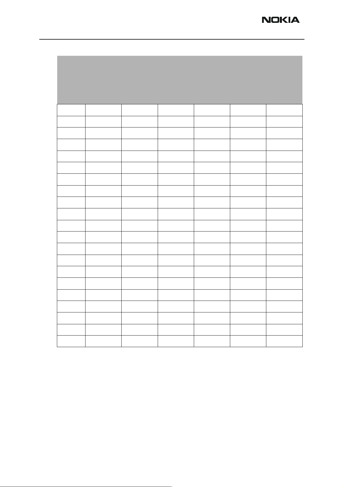
Table 4: TME-1 RF Output Power values
Power
level
0 --- --- --- + 29.5 + 29.5 + 29.5
1 --- --- --- + 28
2 --- --- --- + 26
3 --- --- --- + 24
4 --- --- --- + 22
5 + 32.5 + 32.5 + 32.5 + 20
6+ 31 + 18
7 + 29 + 16 + 16 + 16
8 + 27 + 14
9 + 25 + 12
10 + 23 + 10
Output Power [dBm]
BAND=GSM 900 BAND=GSM 1800
CH=1 CH=60 CH=124 CH=512 CH=700 CH=885
11 + 21 + 8
12 + 19 + 19 + 19 + 6.5
13 + 17 + 5
14 + 15 + 3.5
15 + 13 + 2 + 2 + 2
16 + 11 --- --- ---
17 + 9.5 --- --- ---
18 + 8 --- --- ---
19 + 6.5 + 6.5 + 6.0 --- --- ---
Base - 15 - 23
Page 12 ãNokia Mobile Phones Ltd. Issue 1
Page 13

TME-1
PAMS Technical Documentation Tuning and Flashing Instructions
TME-1 SW Upgrade (flashing)
General
This quide gives instructions how to flash TME-1 and DTX-1.
DTX-1 and TME-1 has different kinds of memory circuits. Due to this the FPS-4 needs to
be configured before flashing. Both devices use different secondary boot code, and you
need to tell to FPS-4 manually which secondary boot code will be used.
NOTE! It is recommended that a second FPS-4 is configured and reserved for flashing of
the DTX-1.
Connections when flashing TME-1
• Connect the the DKT-6A between the FLA-7 and FLA-26.
• Connect the FLA-26 adapter on the TME-1 module.
• Connect the DTX-1 module on the FLA-26.
• Connect the PCS-1 power cable between the FLA-26 and FLA-7.
Be sure that the FPS-4 flash box is configured to flash the TME-1.
NOTE! When flashing the TME-1 module, the DTX-1 does not have to be connected!
Connections when flashing DTX-1
• Connect the DKT-6A cable from the FLA-7 to the connector labeled "TRUNK"
on the DTX-1.
• Connect the FLA-26 adapter on the TME-1 module.
• Connect the DTX-1 module on the FLA-26.
• Connect the PCS-1 power cable between the FLA-26 and FLA-7.
Be sure that the FPS-4 flash box is configured to flash the TME-1.
NOTE! When flashing the DTX-1 module, the TME-1 must be connected!
Before updating the modules it is recomended to save the customer specific settings
with the Nokia 22 Configurator software.
Wintesla settings
Following rows will be added to the tesla.ini by the installation program:
[RPM-3]
UserInterface=TME-1
Functionality=TME-1
Issue 1 ãNokia Mobile Phones Ltd. Page 13
Page 14

TME-1
Tuning and Flashing Instructions PAMS Technical Documentation
FlashImageDirectory=C:\Wintesla\RPM-3
[DTX-1]
UserInterface=TME-1
Functionality=TME-1
FlashImageDirectory=C:\Wintesla\DTX-1
Installation program creates also three folders, RPM-3, DTX-1 and FPS-4 under WinTesla
folder.
Configuring FPS-4
Because of the DTX-1 and TME-1 has different kind of memory circuit, the FPS-4 need
to be configured before flashing. Both devices use different secondary boot code, and
you need to tell to FPS-4 manually which secondary boot code will be used.
The corresponding secondary boot code will be changed with the fps4.exe program.
Device Secondary boot code
TME-1 DCT3BT2.tia
DTX-1 DTX1SEC1.bin
• boot your PC to the DOS mode
• go to FPS4 directory
• if you want to flash DTX-1, write:
fps4 –Ls0DTX1SEC1.bin [ENTER]
• if you want to flash TME-1, write:
fps4 –Ls0DCT3BT2.tia [ENTER]
• restart your PC to Windows
• start WinTesla
• select the product to be flashed.
NOTE! It is recomended that a second FPS-4 is configured and reserved for flashing of
the DTX-1.
Page 14 ãNokia Mobile Phones Ltd. Issue 1
Page 15

TME-1
PAMS Technical Documentation Tuning and Flashing Instructions
Startup of WinTesla
Getting started
If you want to flash the terminal, you need to select either TME-1 or DTX-1 (the one you
want to flash). In service use, both RPM-3 (TME-1) or DTX-1 can be selected, they both
contain same functions.
Flashing
First select the device that will be flashed: Product -> Open…
Figure 3: Select RPM-3 to flash the terminal module
Figure 4: Select DTX-1 to flash the application module
Select Dealer -> Flash -> Phone (or AM).
Issue 1 ãNokia Mobile Phones Ltd. Page 15
Page 16

TME-1
Tuning and Flashing Instructions PAMS Technical Documentation
From the window below, set the correct Market Area and MCU Image File.
Press Flash to start or Close to exit Flash menu
Figure 5: Market Area selection.
Figure 6: MCU Image file selection
A dialog box will appear to display the progress of flashing. Do not start or use any other
application during flashing.
All five LEDs of the TME-1 are lit during programming. After the new software is flashed
to the memory circuit, the main window will appear again:
Page 16 ãNokia Mobile Phones Ltd. Issue 1
Page 17

TME-1
PAMS Technical Documentation Tuning and Flashing Instructions
Figure 7: Flashing
Flash another DTX-1 (or TME1) by pressing Flash, or exit from the 'Flash Phone' menu by
pressing Close
Issue 1 ãNokia Mobile Phones Ltd. Page 17
Page 18

TME-1
Tuning and Flashing Instructions PAMS Technical Documentation
Flashing TME-1
When flashing TME-1, a dialog box below will appear to ask if you want to save the user
settings to the file before flashing
Figure 8: Dialog box.
Figure 6.: Possibility to save user data to a file
A dialog box will appear again to display the progress of flashing. Do not start or use any
other application during flashing. All five LEDs of the TME-1 are lit during programming.
After the new software is flashed to the memory circuit, a dialog box will appear that
allows you to restore the user settings to the TME-1.
Figure 9: Restoring default user settings
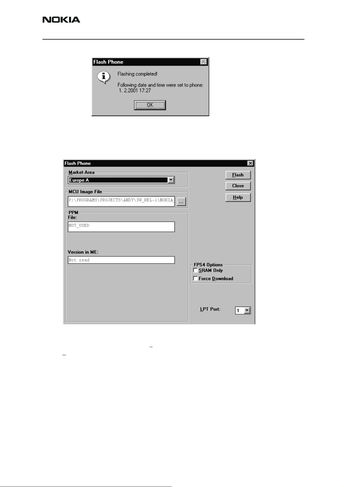
After succesful flash step you will get a following dialog box:
Page 18 ãNokia Mobile Phones Ltd. Issue 1
Page 19
TME-1
PAMS Technical Documentation Tuning and Flashing Instructions
Figure 10: Dialog Box
By pressing OK you will return to Flash Phone dialog box.
Figure 11: Flash Phone Dialog box
Flash another TME1 by pressing Flash, or exit from the 'Flash Phone' menu by pressing
Close
Issue 1 ãNokia Mobile Phones Ltd. Page 19
Page 20

TME-1
Tuning and Flashing Instructions PAMS Technical Documentation
Restore Country specific settings
After flashing the TME-1 or DTX-1 it is needed to restore factory settings.
In Wintesla, select Software - Set Factory Values.
Select GSM Teminal Data - OK.
Select PBX application data - OK.
Product code specific settings are restored using the Configurator software.
Customer specific settings are restored using the Configurator software and respective
saved file.
Page 20 ãNokia Mobile Phones Ltd. Issue 1
 Loading...