

Nissan Pathfinder 2008 User Manual

TRANSMISSION & DRIVELINE
A
B
SECTION DLN
CONTENTS
TRANSFER: ATX14B
BASIC INSPECTION ....................................
DIAGNOSIS AND REPAIR WORKFLOW ..........8
Work Flow .................................................................8
Preliminary Check .....................................................9
FUNCTION DIAGNOSIS ..............................12
4WD SYSTEM ....................................................12
System Diagram ......................................................12
System Description .................................................13
Component Parts Location . .....................................18
CAN Communication ...............................................19
DIAGNOSIS SYSTEM (TRANSFER CON-
TROL UNIT) ........................................................
CONSULT-III Function (ALL MODE AWD/4WD) ....20
NOISE, VIBRATION AND HARSHNESS
(NVH) TROUBLESHOOTING ............................
NVH Troubleshooting Chart ....................................24
COMPONENT DIAGNOSIS .........................25
P1811 POWER SUPPLY CIRCUIT FOR
TRANSFER CONTROL UNIT ............................
Description ..............................................................25
DTC Logic ...............................................................25
Diagnosis Procedure ........................... ... ... ... .... .......25
Component Inspection .... ... .... ... ..............................26
P1802 – P1804, P1809 TRANSFER CON-
TROL UNIT .........................................................
Description ..............................................................27
DTC Logic ...............................................................27
Diagnosis Procedure ........................... ... ... ... .... .......27
P1807 VEHICLE SPEED SENSOR (A/T) ..........29
Description ..............................................................29
DTC Logic ...............................................................29
20
24
25
27
DRIVELINE
Diagnosis Procedure ...............................................29
P1808 VEHICLE SPEED SENSOR (ABS) .......30
8
Description .......................... ... ....... ...... ....... ...... ........30
DTC Logic ................................................................30
Diagnosis Procedure ...............................................30
P1810 NEUTRAL-4LO SWITCH .......................31
Description .......................... ... ....... ...... ....... ...... ........31
DTC Logic ................................................................31
Diagnosis Procedure ...............................................31
Component Inspection .............................................33
P1813 4WD SHIFT SWITCH .............................34
Description .......................... ... ....... ...... ....... ...... ........34
DTC Logic ................................................................34
Diagnosis Procedure ...............................................34
Component Inspection .............................................36
P1814 WAIT DETECTION SWITCH .................38
Description .......................... ... ....... ...... ....... ...... ........38
DTC Logic ................................................................38
Diagnosis Procedure ...............................................38
Component Inspection .............................................40
P1816 PNP SWITCH .........................................41
Description .......................... ... ....... ...... ....... ...... ........41
DTC Logic ................................................................41
Diagnosis Procedure ...............................................41
P1817 ACTUATOR MOTOR .............................42
Description .......................... ... ....... ...... ....... ...... ........42
DTC Logic ................................................................42
Diagnosis Procedure ...............................................42
Component Inspection .............................................46
P1818 ACTUATOR POSITION SWITCH ..........48
Description .......................... ... ....... ...... ....... ...... ........48
DTC Logic ................................................................48
Diagnosis Procedure ...............................................48
Component Inspection .........................................
....
C
DLN
E
F
G
H
I
J
K
L
M
N
O
P
50
DLN-1

P1819 TRANSFER CONTROL DEVICE ...........51
Description ....................... .......................... ............. 51
DTC Logic ............................................................... 51
Diagnosis Procedure .............................................. 51
P1832 TCS OPERATION SIGNAL (ABS) ......... 82
Description ..............................................................82
DTC Logic .............. ... ..............................................82
Diagnosis Procedure ..... ... .......................................82
P1820 ENGINE SPEED SIGNAL ...................... 55
Description ....................... .......................... ............. 55
DTC Logic ............................................................... 55
Diagnosis Procedure .............................................. 55
P1822 CLUTCH PRESSURE SOLENOID .........56
Description ....................... .......................... ............. 56
DTC Logic ............................................................... 56
Diagnosis Procedure .............................................. 56
Component Inspection ............................................ 58
P1823 2-4 SOLENOID .......................................60
Description ....................... .......................... ............. 60
DTC Logic ............................................................... 60
Diagnosis Procedure .............................................. 60
Component Inspection ............................................ 63
P1824 TRANSFER MOTOR ..............................64
Description ....................... .......................... ............. 64
DTC Logic ............................................................... 64
Diagnosis Procedure .............................................. 64
Component Inspection ............................................ 68
P1826 TRANSFER FLUID TEMPERATURE .... 70
Description ....................... .......................... ............. 70
DTC Logic ............................................................... 70
Diagnosis Procedure .............................................. 70
Component Inspection ............................................ 71
P1827 CLUTCH PRESSURE SWITCH .............73
Description ....................... .......................... ............. 73
DTC Logic ............................................................... 73
Diagnosis Procedure .............................................. 73
Component Inspection ............................................ 74
P1828 LINE PRESSURE SWITCH .................... 76
Description ....................... .......................... ............. 76
DTC Logic ............................................................... 76
Diagnosis Procedure .............................................. 76
Component Inspection ............................................ 78
P1829 THROTTLE POSITION SIGNAL (ECM)
79
...
Description ....................... .......................... ............. 79
DTC Logic ............................................................... 79
Diagnosis Procedure .............................................. 79
P1830 ABS OPERATION SIGNAL (ABS) ........ 80
Description ....................... .......................... ............. 80
DTC Logic ............................................................... 80
Diagnosis Procedure .............................................. 80
P1831 VDC OPERATION SIGNAL (ABS) ........ 81
Description ....................... .......................... ............. 81
DTC Logic ............................................................... 81
Diagnosis Procedure .............................................. 81
ECU DIAGNOSIS ....................................... 83
TRANSFER CONTROL UNIT ........................... 83
Reference Value .....................................................83
Wiring Diagram .......................................................91
DTC Index ........................................... ... .... ... ........ 101
SYMPTOM DIAGNOSIS ...........................106
4WD SYSTEM SYMPTOMS .............................106
Symptom Table ..................................................... 106
4WD SHIFT INDICATOR LAMP AND 4LO IN-
DICATOR LAMP DO NOT TURN ON ..............
Description ............................................................ 107
Diagnosis Procedure ..... ... ..................................... 107
107
4WD WARNING LAMP DOES NOT TURN ON ..110
Description ............................................................ 110
Diagnosis Procedure ..... ... ..................................... 110
4WD SHIFT INDICATOR LAMP OR 4LO INDI-
CATOR LAMP DO NOT CHANGE ...................
Description ............................................................ 113
Diagnosis Procedure ..... ... ..................................... 113
113
ATP WARNING LAMP DOES NOT TURN ON ..115
Description ............................................................ 115
Diagnosis Procedure ..... ... ..................................... 115
4WD SHIFT INDICATOR LAMP KEEPS
FLASHING ........................................................
Description ............................................................ 117
Diagnosis Procedure ..... ... ..................................... 117
117
4WD WARNING LAMP FLASHES RAPIDLY ..118
Description ............................................................ 118
Diagnosis Procedure ..... ... ..................................... 118
4WD WARNING LAMP FLASHES SLOWLY ..119
Description ............................................................ 119
Diagnosis Procedure ..... ... ..................................... 119
HEAVY TIGHT-CORNER BRAKING SYMP-
TOM OCCURS ..................................................
Description ............................................................ 120
Diagnosis Procedure ..... ... ..................................... 120
120
ATP SWITCH ....................................................122
Description ............................................................ 122
Diagnosis Procedure ..... ... ..................................... 122
4WD SYSTEM DOES NOT OPERATE ............124
Description ............................................................ 124
Diagnosis Procedure ..... ... ..................................... 124
PRECAUTION ...........................................125
DLN-2

PRECAUTIONS ................................................125
Precaution for Supplemental Restrain t System
(SRS) "AIR BAG" and "SEAT BELT PRE-TEN-
SIONER" ...............................................................
Precaution for Transfer Assembly and Transfer
Control Unit Replacement .....................................
Precaution .............................................................126
Service Notice .......................................................126
125
125
PREPARATION .........................................128
PREPARATION ................................................128
Special Service Tool ................................. ... .... .....128
Commercial Service Tool ......................................131
ON-VEHICLE MAINTENANCE ..................132
TRANSFER FLUID ...........................................132
Replacement .........................................................132
Inspection ..................... .........................................132
TRANSFER OIL FILTER ..................................133
Removal and Installation .......................................133
ON-VEHICLE REPAIR ...............................135
TRANSFER CONTROL UNIT ..........................135
Removal and Installation .......................................135
FRONT OIL SEAL ............................................136
Removal and Installation .......................................136
REAR OIL SEAL ..............................................138
Removal and Installation .......................................138
SIDE OIL SEAL ................................................140
Removal and Installation .......................................140
TRANSFER CONTROL DEVICE .....................141
Removal and Installation .......................................141
AIR BREATHER HOSE ....................................142
Removal and Installation .......................................142
TRANSFER MOTOR ........................................147
Removal and Installation .......................................147
Inspection and Adjustment ....................................186
TRANSFER: TX15B
BASIC INSPECTION .................................188
DIAGNOSIS AND REPAIR WORKFLOW ...... 188
Work Flow ..............................................................188
FUNCTION DIAGNOSIS ............................ 190
4WD SYSTEM ................................................. 190
System Diagram ....................................................190
System Description ................................................191
Component Parts Location ....................................193
CAN Communication .............................................194
Cross-Sectional View ............................................194
Power Transfer ......................................................195
DIAGNOSIS SYSTEM (TRANSFER CON-
TROL UNIT) ....................................................
CONSULT-III Function (ALL MODE AWD/4WD) ..197
197
NOISE, VIBRATION AND HARSHNESS
(NVH) TROUBLESHOOTING .........................
NVH Troubleshooting Chart ..................................200
200
COMPONENT DIAGNOSIS .......................201
P1801, P1811 POWER SUPPLY CIRCUIT
FOR TRANSFER CONTROL UNIT ................
Description .......................... ... ....... ...... ....... ...... ......201
DTC Logic ..............................................................201
Diagnosis Procedure .............................................201
Component Inspection ...........................................203
P1802 – P1804, P1809 TRANSFER CON-
TROL UNIT ......................................................
Description .......................... ... ....... ...... ....... ...... ......204
DTC Logic ..............................................................204
Diagnosis Procedure .............................................204
P1807 VEHICLE SPEED SENSOR (A/T) .......206
Description .......................... ... ....... ...... ....... ...... ......206
DTC Logic ..............................................................206
Diagnosis Procedure .............................................206
201
204
A
B
C
DLN
E
F
G
H
I
J
K
L
M
REMOVAL AND INSTALLATION .............148
TRANSFER ASSEMBLY .................................148
Removal and Installation .......................................148
DISASSEMBLY AND ASSEMBLY ............149
TRANSFER ASSEMBLY .................................149
Disassembly and Assembly ...... ... .........................149
SERVICE DATA AND SPECIFICATIONS
(SDS) ..........................................................
SERVICE DATA AND SPECIFICATIONS
(SDS) ................................................................
General Specification ............................................186
186
186
DLN-3
P1808 VEHICLE SPEED SENSOR (ABS) .....207
Description .......................... ... ....... ...... ....... ...... ......207
DTC Logic ..............................................................207
Diagnosis Procedure .............................................207
P1810 4 LO SWITCH ......................................208
Description .......................... ... ....... ...... ....... ...... ......208
DTC Logic ..............................................................208
Diagnosis Procedure .............................................208
Component Inspection ...........................................210
P1813 4WD SHIFT SWITCH ...........................211
Description .......................... ... ....... ...... ....... ...... ......211
DTC Logic ..............................................................211
Diagnosis Procedure .............................................211
N
O
P

Component Inspection ...........................................213
Diagnosis Procedure ..... ... ..................................... 255
P1814 WAIT DETECTION SWITCH ................ 214
Description ....................... .......................... ............214
DTC Logic ..............................................................214
Diagnosis Procedure .............................................214
Component Inspection ...........................................216
P1816 PNP SWITCH ....................................... 217
Description ....................... .......................... ............217
DTC Logic ..............................................................217
Diagnosis Procedure .............................................217
P1817 ACTUATOR MOTOR ........................... 218
Description ....................... .......................... ............218
DTC Logic ..............................................................218
Diagnosis Procedure .............................................218
Component Inspection ...........................................223
P1818 ACTUATOR POSITION SWITCH ........ 225
Description ....................... .......................... ............225
DTC Logic ..............................................................225
Diagnosis Procedure .............................................225
P1819 TRANSFER CONTROL DEVICE ......... 228
Description ....................... .......................... ............228
DTC Logic ..............................................................228
Diagnosis Procedure .............................................228
4WD SHIFT INDICATOR LAMP KEEPS
FLASHING ........................................................
Description ............................................................ 257
Diagnosis Procedure ..... ... ..................................... 257
257
4WD WARNING LAMP FLASHES SLOWLY ..258
Description ............................................................ 258
Diagnosis Procedure ..... ... ..................................... 258
ATP SWITCH ....................................................259
Description ............................................................ 259
Diagnosis Procedure ..... ... ..................................... 259
Component Inspection .......................................... 260
PRECAUTION ...........................................262
PRECAUTIONS ................................................262
Precaution for Supplemental Restraint System
(SRS) "AIR BAG" and "SEAT BELT PRE-TEN-
SIONER" ............................. ..................................
Precaution for Transfer Assembly and Transfer
Control Unit Replacement .....................................
Precaution ........................ ..................................... 264
Service Notice ..................................... ... .... ... ... ... .. 264
262
262
PREPARATION .........................................266
P1820 ENGINE SPEED SIGNAL .................... 231
Description ....................... .......................... ............231
DTC Logic ..............................................................231
Diagnosis Procedure .............................................231
ECU DIAGNOSIS .......................................232
TRANSFER CONTROL UNIT .......................... 232
Reference Value ..................... ... ... ... ......................232
Wiring Diagram ......................................................237
DTC Index .............................................................245
SYMPTOM DIAGNOSIS ............................248
4WD SYSTEM SYMPTOMS ............................ 248
Symptom Table .................. .... ... ............................248
4WD WARNING LAMP DOES NOT TURN ON . 249
Description ....................... .......................... ............249
Diagnosis Procedure .............................................249
4WD SHIFT INDICATOR LAMP AND 4LO IN-
DICATOR LAMP DO NOT TURN ON .............
Description ....................... .......................... ............251
Diagnosis Procedure .............................................251
4WD SHIFT INDICATOR LAMP OR 4LO INDI-
CATOR LAMP DO NOT CHANGE ..................
Description ....................... .......................... ............253
Diagnosis Procedure .............................................253
ATP WARNING LAMP DOES NOT TURN ON . 255
Description ....................... .......................... ............255
251
253
PREPARATION ................................................266
Special Service Tool ..................... ... ... ... .... ... ... ..... 266
Commercial Service Tool ........................... ... ... ..... 268
ON-VEHICLE MAINTENANCE ................. 269
TRANSFER FLUID ...........................................269
Replacement .................... ..................................... 269
Inspection ......................... ................ ................ ..... 269
ON-VEHICLE REPAIR ..............................270
TRANSFER CONTROL UNIT ..........................270
Removal and Installation ....................................... 270
FRONT OIL SEAL ............................................271
Removal and Installation ....................................... 271
REAR OIL SEAL ..............................................273
Removal and Installation ....................................... 273
TRANSFER CONTROL DEVICE .....................275
Removal and Installation ....................................... 275
AIR BREATHER HOSE ....................................277
Removal and Installation ....................................... 277
PLANETARY CARRIER ...................................279
Disassembly and Assembly .................................. 279
FRONT DRIVE SHAFT .....................................283
Disassembly and Assembly .................................. 283
SHIFT CONTROL .............................................285
DLN-4

Disassembly and Assembly ...... ... .........................
285
REMOVAL AND INSTALLATION .............287
TRANSFER ASSEMBLY .................................287
Removal and Installation .......................................287
DISASSEMBLY AND ASSEMBLY ............288
TRANSFER ASSEMBLY .................................288
Disassembly and Assembly ...... ... .........................288
SERVICE DATA AND SPECIFICATIONS
(SDS) ..........................................................304
SERVICE DATA AND SPECIFICATIONS
(SDS) ................................................................
General Specification ............................................304
Inspection and Adjustment ........................ ............304
304
PROPELLER SHAFT: 2F1310
PREPARATION .........................................305
PREPARATION ................................................305
Commercial Service Tool ......................................305
FUNCTION DIAGNOSIS ............................ 306
NOISE, VIBRATION, AND HARSHNESS
(NVH) TROUBLESHOOTING .........................
NVH Troubleshooting Chart ..................................314
314
ON-VEHICLE REPAIR ............................... 315
PROPELLER SHAFT ......................................315
On-Vehicle Service .......................................... ... ...315
REMOVAL AND INSTALLATION .............316
PROPELLER SHAFT ......................................316
Removal and Installation .......................................316
DISASSEMBLY AND ASSEMBLY ............ 318
PROPELLER SHAFT ......................................318
Disassembly and Assembly ...................................318
SERVICE DATA AND SPECIFICATIONS
(SDS) ..........................................................320
SERVICE DATA AND SPECIFICATIONS
(SDS) ...............................................................
General Specification ............................................320
Snap Ring . .... .........................................................321
320
PROPELLER SHAFT: 2S1350
A
B
C
DLN
E
F
G
H
NOISE, VIBRATION, AND HARSHNESS
(NVH) TROUBLESHOOTING ..........................
NVH Troubleshooting Chart ..................................306
306
ON-VEHICLE REPAIR ...............................307
PROPELLER SHAFT .......................................307
On-Vehicle Service ...............................................307
REMOVAL AND INSTALLATION .............308
PROPELLER SHAFT .......................................308
Removal and Installation .......................................308
DISASSEMBLY AND ASSEMBLY ............310
PROPELLER SHAFT .......................................310
Disassembly and Assembly ...... ... .........................310
SERVICE DATA AND SPECIFICATIONS
(SDS) ..........................................................
SERVICE DATA AND SPECIFICATIONS
(SDS) ................................................................
General Specification ............................................312
Snap Ring .............................................................312
312
312
PROPELLER SHAFT: 2S1330
PREPARATION .........................................313
PREPARATION ................................................313
Commercial Service Tool ......................................313
FUNCTION DIAGNOSIS ............................ 314
PREPARATION .........................................322
PREPARATION ...............................................322
Commercial Service Tool ......................................322
FUNCTION DIAGNOSIS ............................ 323
NOISE, VIBRATION, AND HARSHNESS
(NVH) TROUBLESHOOTING .........................
NVH Troubleshooting Chart ..................................323
323
ON-VEHICLE REPAIR ............................... 324
PROPELLER SHAFT ......................................324
On-Vehicle Service .......................................... ... ...324
REMOVAL AND INSTALLATION .............325
PROPELLER SHAFT ......................................325
Removal and Installation .......................................325
DISASSEMBLY AND ASSEMBLY ............ 327
PROPELLER SHAFT ......................................327
Disassembly and Assembly ...................................327
SERVICE DATA AND SPECIFICATIONS
(SDS) ..........................................................329
SERVICE DATA AND SPECIFICATIONS
(SDS) ...............................................................
General Specification ............................................329
Snap Ring . .... .........................................................330
329
FRONT FINAL DRIVE: R180A
I
J
K
L
M
N
O
P
DLN-5

PRECAUTION ............................................331
PRECAUTIONS ............................................... 331
Precaution for Servicing Front Final Drive .............331
PREPARATION ..........................................332
PREPARATION ............................................... 332
Special Service Tool ..............................................332
Commercial Service Tool ................ .... ..................334
FUNCTION DIAGNOSIS ............................336
NOISE, VIBRATION AND HARSHNESS
(NVH) TROUBLESHOOTING ..........................
NVH Troubleshooting Chart ............ .... ..................336
336
DESCRIPTION ................................................. 337
Cross-Sectional View ............................................337
ON-VEHICLE MAINTENANCE ..................338
DIFFERENTIAL GEAR OIL ............................. 338
Changing Differential Gear Oil ...............................338
Checking Differential Gear Oil ...............................338
ON-VEHICLE REPAIR ...............................339
FRONT OIL SEAL ........................................... 339
Removal and Installation .......................................339
SIDE OIL SEAL ............................................... 341
Removal and Installation .......................................341
PREPARATION ................................................367
Special Service Tool ..................... ... ... ... .... ... ... ..... 367
Commercial Service Tool ........................... ... ... ..... 369
FUNCTION DIAGNOSIS ...........................370
NOISE, VIBRATION AND HARSHNESS
(NVH) TROUBLESHOOTING ...........................
NVH Troubleshooting Chart .................................. 370
370
ON-VEHICLE MAINTENANCE ................. 371
DIFFERENTIAL GEAR OIL ..............................371
Changing Differential Gear Oil .............................. 371
Checking Differential Gear Oil ............................ .. 371
ON-VEHICLE REPAIR ..............................372
SIDE OIL SEAL ................................................372
Removal and Installation ....................................... 372
FRONT OIL SEAL ............................................373
Removal and Installation ....................................... 373
CARRIER COVER ............................................375
Removal and Installation ....................................... 375
REMOVAL AND INSTALLATION ............. 376
FRONT FINAL DRIVE ......................................376
Removal and Installation ....................................... 376
DISASSEMBLY AND ASSEMBLY ........... 378
CARRIER COVER ........................................... 342
Removal and Installation .......................................342
REMOVAL AND INSTALLATION ..............343
FRONT FINAL DRIVE ASSEMBLY ................ 343
Removal and Installation .......................................343
DISASSEMBLY AND ASSEMBLY ............345
FRONT FINAL DRIVE ..................................... 345
Disassembly and Assembly ................................... 345
SERVICE DATA AND SPECIFICATIONS
(SDS) ..........................................................364
SERVICE DATA AND SPECIFICATIONS
(SDS) ................................................................
General Specification ................ ... ... .... ..................364
Inspection and Adjustment ....................................364
364
FRONT FINAL DRIVE: M205
PRECAUTION ............................................
PRECAUTIONS ............................................... 366
Precaution for Servicing Front Final Drive .............366
366
PREPARATION ..........................................367
FRONT FINAL DRIVE ......................................378
Disassembly and Assembly .................................. 378
SERVICE DATA AND SPECIFICATIONS
(SDS) .........................................................395
SERVICE DATA AND SPECIFICATIONS
(SDS) ................................................................
General Specification ............................................395
Inspection and Adjustment .................................... 395
395
REAR FINAL DRIVE: R200
PRECAUTION ...........................................
PRECAUTIONS ................................................397
Precaution for Servicing Rear Final Drive ............. 397
397
PREPARATION .........................................398
PREPARATION ................................................398
Special Service Tool ..................... ... ... ... .... ... ... ..... 398
Commercial Service Tool ........................... ... ... ..... 401
FUNCTION DIAGNOSIS ...........................402
NOISE, VIBRATION AND HARSHNESS
(NVH) TROUBLESHOOTING ...........................
NVH Troubleshooting Chart .................................. 402
402
DLN-6

DESCRIPTION .................................................403
Cross-Sectional View ............................................403
Special Service Tool ..............................................435
Commercial Service Tool ......................................438
A
ON-VEHICLE MAINTENANCE ..................404
DIFFERENTIAL GEAR OIL ..............................404
Changing Differential Gear Oil ..............................404
Checking Differential Gear Oil ...............................404
ON-VEHICLE REPAIR ...............................405
FRONT OIL SEAL ............................................405
Removal and Installation .......................................405
SIDE OIL SEAL ................................................407
Removal and Installation .......................................407
CARRIER COVER ............................................409
Removal and Installation .......................................409
REMOVAL AND INSTALLATION .............410
REAR FINAL DRIVE ........................................410
Removal and Installation .......................................410
DISASSEMBLY AND ASSEMBLY ............413
REAR FINAL DRIVE ........................................413
Disassembly and Assembly ...... ... .........................413
SERVICE DATA AND SPECIFICATIONS
(SDS) ..........................................................432
SERVICE DATA AND SPECIFICATIONS
(SDS) ................................................................
General Specification ............................................432
Inspection and Adjustment ........................ ............432
432
REAR FINAL DRIVE: R230 (4WD)
PRECAUTION ............................................434
PRECAUTIONS ................................................434
Precaution for Servicing Rear Final Drive .............434
PREPARATION .........................................435
PREPARATION ................................................435
FUNCTION DIAGNOSIS ............................ 439
NOISE, VIBRATION AND HARSHNESS
(NVH) TROUBLESHOOTING .........................
NVH Troubleshooting Chart ..................................439
439
DESCRIPTION ................................................ 440
Cross-Sectional View ............................................440
ON-VEHICLE MAINTENANCE .................. 441
DIFFERENTIAL GEAR OIL ............................441
Changing Differential Gear Oil ...............................441
Checking Differential Gear Oil ...............................441
ON-VEHICLE REPAIR ............................... 442
FRONT OIL SEAL ...........................................442
Removal and Installation .......................................442
SIDE OIL SEAL ...............................................444
Removal and Installation .......................................444
CARRIER COVER ........................................... 446
Removal and Installation .......................................446
REMOVAL AND INSTALLATION .............447
REAR FINAL DRIVE ....................................... 447
Removal and Installation .......................................447
DISASSEMBLY AND ASSEMBLY ............ 450
REAR FINAL DRIVE ....................................... 450
Disassembly and Assembly ...................................450
SERVICE DATA AND SPECIFICATIONS
(SDS) ..........................................................
SERVICE DATA AND SPECIFICATIONS
(SDS) ...............................................................
General Specification ............................................466
Inspection and Adjustment ....................................466
466
466
B
C
DLN
E
F
G
H
I
J
K
L
M
N
DLN-7
O
P
DIAGNOSIS AND REPAIR WORKFLOW
B
< BASIC INSPECTION >
[TRANSFER: ATX14B]
BASIC INSPECTION
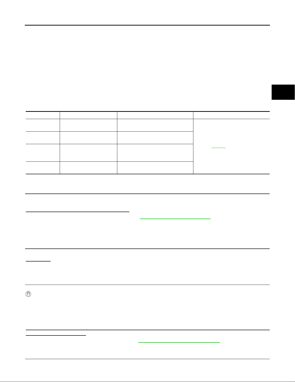
DIAGNOSIS AND REPAIR WORKFLOW
Work Flow INFOID:0000000001728331
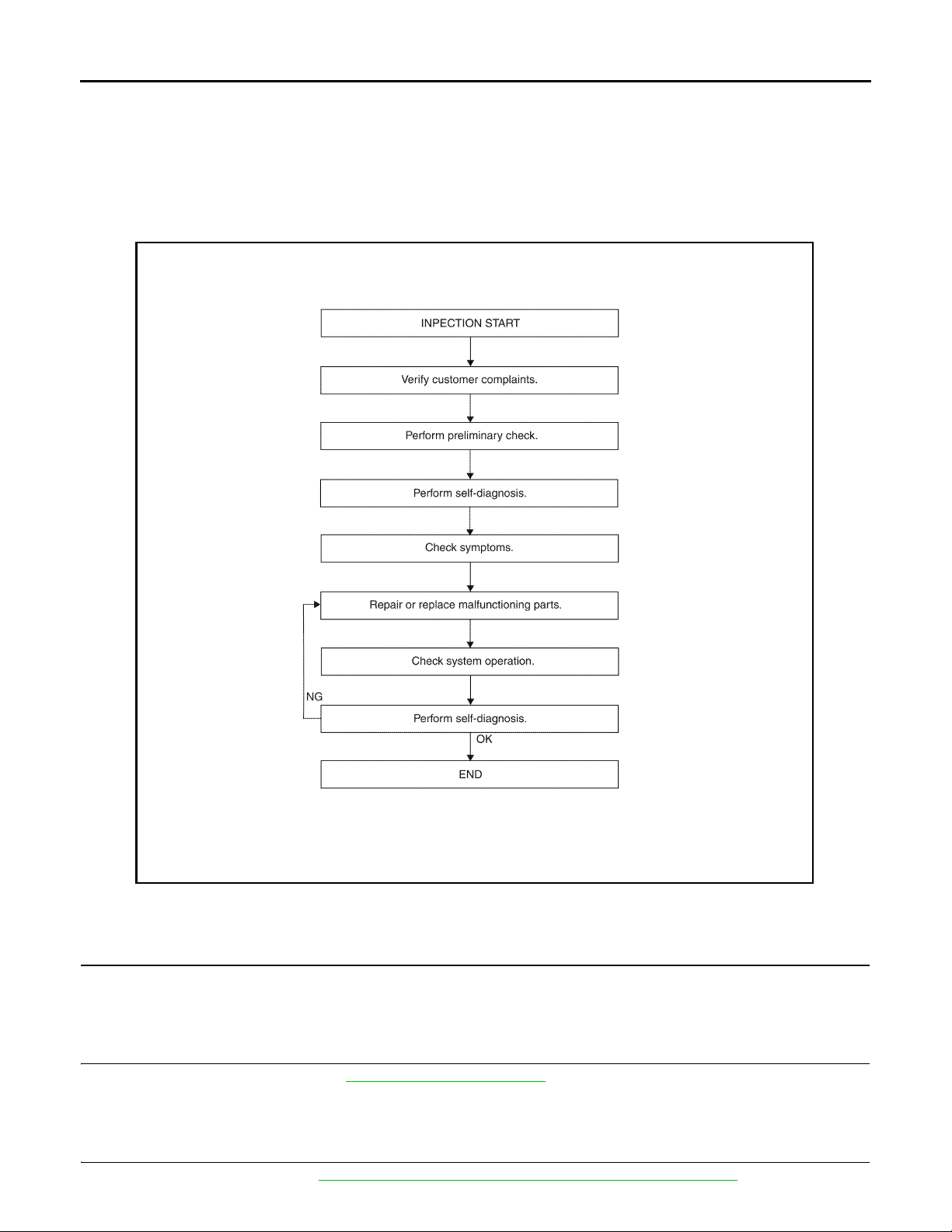
WORK FLOW
DETAILED FLOW
1.CUSTOMER INFORMATION
Interview the customer to obtain detailed information about the symptom.
>> GO TO 2
2.PRELIMINARY CHECK
Perform preliminary check. Refer to DLN-9, "
>> GO TO 3
Preliminary Check".
3.SELF-DIAGNOSIS
Perform self-diagnosis. Refer to DLN-20, "
CONSULT-III Function (ALL MODE AWD/4WD)".
DLN-8
AWNIA0126G
< BASIC INSPECTION >
DIAGNOSIS AND REPAIR WORKFLOW
[TRANSFER: ATX14B]
>> GO TO 4
4.SYMPTOM
Check for symptoms. Refer to DLN-106, "
>> GO TO 5
Symptom Table".
5.MALFUNCTIONING PARTS
Repair or replace the applicable parts.
>> GO TO 6
6.SYSTEM OPERATION
Check system operation.
>> GO TO 7
7.SELF-DIAGNOSIS
Perform self-diagnosis.
Are any DTC's displayed?
YES >> GO TO 5
NO >> Inspection End
Preliminary Check INFOID:0000000001728332
A
B
C
DLN
E
F
G
H
TRANSFER FLUID CHECK
Check for leaks and fluid level. Refer to DLN-132, "Inspection".
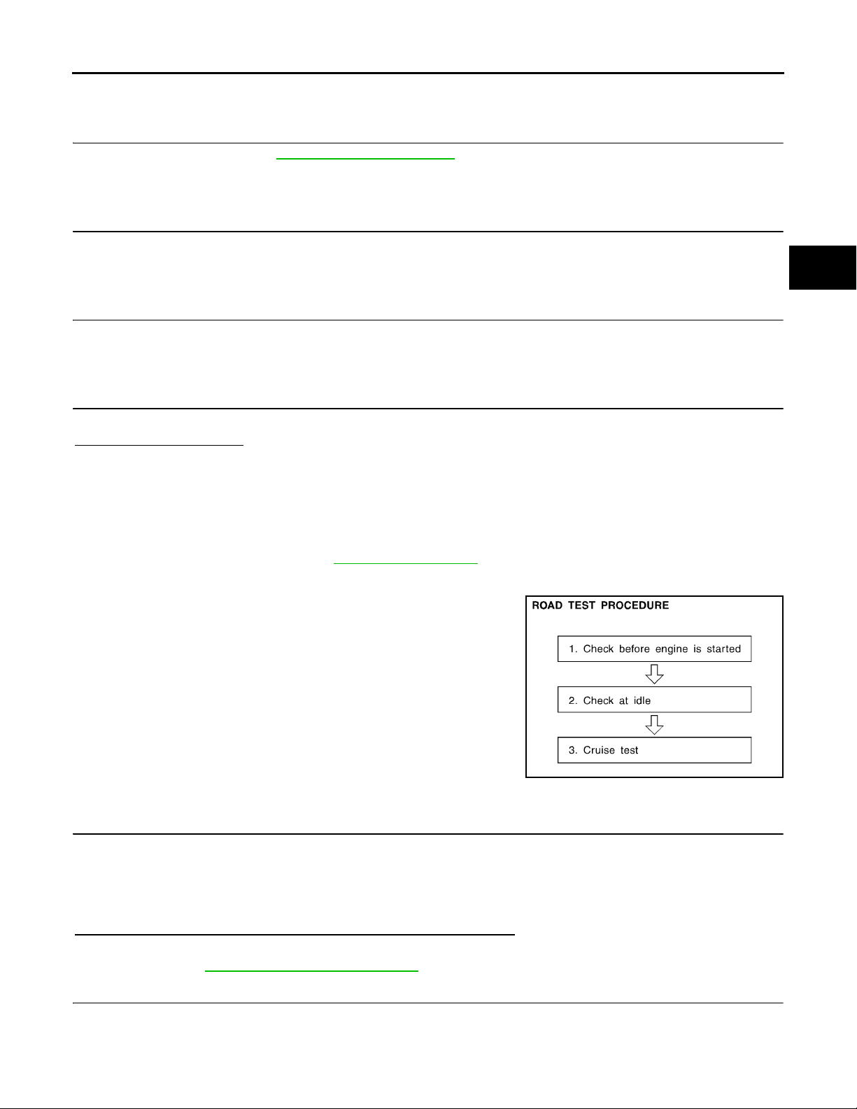
PREPARATION FOR ROAD TEST
The purpose of the test is to determine overall performance of transfer case and analyze causes of malfunctions.
When a malfunction is found in any part of transfer, perform the road
test to locate the malfunction area and repair the malfunction parts.
The road test consists of the following three parts.
1. CHECK BEFORE ENGINE IS STARTED
2. CHECK AT IDLE
3. CRUISE TEST
CHECK BEFORE ENGINE IS STARTED
1.CHECK 4WD SHIFT INDICATOR LAMP
1. Park vehicle on flat surface.
2. Turn ignition switch to OFF position.
3. Move A/T selector lever to P position.
4. Set 4WD shift switch to 2WD position.
5. Turn ignition switch to ON position. (Do not start engine.)
Does 4WD shift indicator lamp turn ON for approximately 1 second?
YES >> GO TO 2.
NO >> GO TO DLN-107, "
Diagnosis Procedure".
2.CHECK 4WD WARNING LAMP
SMT089D
I
J
K
L
M
N
O
P
1. Turn ignition switch to OFF position.
2. Move A/T selector lever to P position.
3. Set 4WD shift switch to 2WD position.
4. Turn ignition switch to ON position. (Do not start engine.)
DLN-9
DIAGNOSIS AND REPAIR WORKFLOW
< BASIC INSPECTION >
Does 4WD warning lamp turn ON?
YES >> GO TO CHECK AT IDLE.
NO >> GO TO DLN-110, "
Diagnosis Procedure".
CHECK AT IDLE
[TRANSFER: ATX14B]
1.CHECK 4WD SHIFT INDICATOR LAMP
1. Park vehicle on flat surface and engage the parking brake.
2. Turn ignition switch to OFF position.
3. Move A/T selector lever to P position.
4. Set 4WD shift switch to 2WD position.
5. Start engine.
Does 4WD shift indicator lamp turn ON?
YES >> GO TO 3.
NO >> GO TO 2.
2.CHECK 4WD WARNING LAMP
Check 4WD warning lamp state.
Is 4WD warning lamp turned ON?
YES >> Perform the self-diagnosis. Refer to DLN-20, "CONSULT-III Function (ALL MODE AWD/4WD)".
NO >> Refer to DLN-113, "
Diagnosis Procedure".
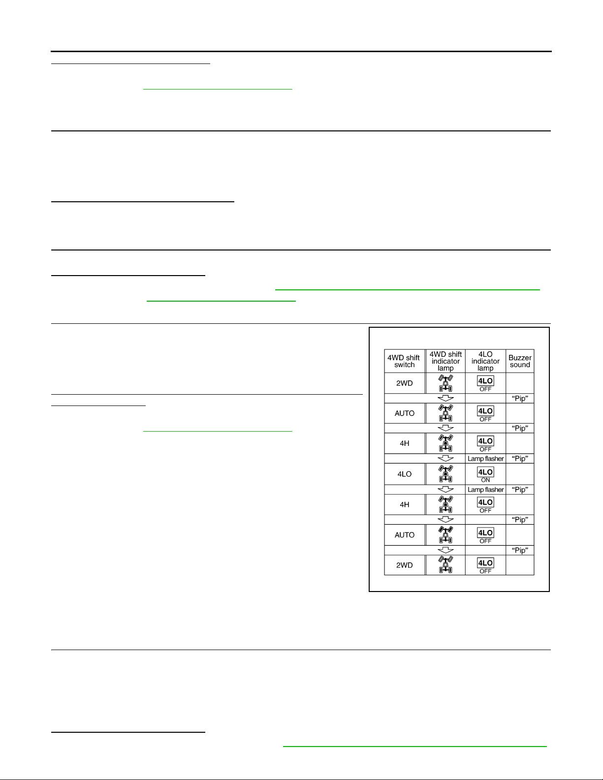
3.CHECK 4WD SHIFT INDICATOR AND 4LO INDICATOR OPERATION
1. Brake pedal depressed.
2. Move A/T selector lever to N position.
3. Set 4WD shift switch to 2WD, AUTO, 4H, 4LO, 4H, AUTO and
2WD in order. (Stay at each switch position for at least 1 second.)
Do 4WD shift indicator and 4LO indicator lamps change properly?
Does buzzer sound?
YES >> GO TO CRUISE TEST.
NO >> GO TO DLN-113, "
Diagnosis Procedure".
CRUISE TEST
WDIA0136E
1.CHECK INPUT SIGNAL
1. Warm up engine to normal operating temperature.
2. Park vehicle on flat surface.
3. Move A/T selector lever to P position.
4. Set 4WD shift switch to AUTO position.
5. Start engine.
6. Drive vehicle for at least 30 seconds at a speed higher than 20 km/h (12 MPH).
Is 4WD warning lamp turned ON?
On steady>>Perform the self-diagnosis. Refer to DLN-20, "CONSULT-III Function (ALL MODE AWD/4WD)".
DLN-10

DIAGNOSIS AND REPAIR WORKFLOW
< BASIC INSPECTION >
Flash rapidly>>Refer to DLN-118, "Diagnosis Procedure".
Flash slowly>>Refer to DLN-119, "
NO >> GO TO 2.
Diagnosis Procedure".
[TRANSFER: ATX14B]
2.CHECK TIGHT CORNER BRAKING SYMPTOM (1)
1. Set 4WD shift switch to AUTO position.
2. Drive vehicle at speed lower than 20 km/h (12 MPH) with steering wheel fully turned.
Does tight corner braking symptom occur?
YES >> GO TO DLN-120, "Diagnosis Procedure".
NO >> GO TO 3.
3.CHECK TIGHT CORNER BRAKING SYMPTOM (2)
1. Set 4WD shift switch to 4HI position.
2. Drive vehicle at speed lower than 20 km/h (12 MPH) with steering wheel fully turned.
Does tight corner braking symptom occur?
YES >> Inspection End.
NO >> GO TO DLN-124, "
Diagnosis Procedure".
A
B
C
DLN
E
F
G
H
K
M
N
O
I
J
L
DLN-11
P
4WD SYSTEM
< FUNCTION DIAGNOSIS >
[TRANSFER: ATX14B]
FUNCTION DIAGNOSIS
4WD SYSTEM
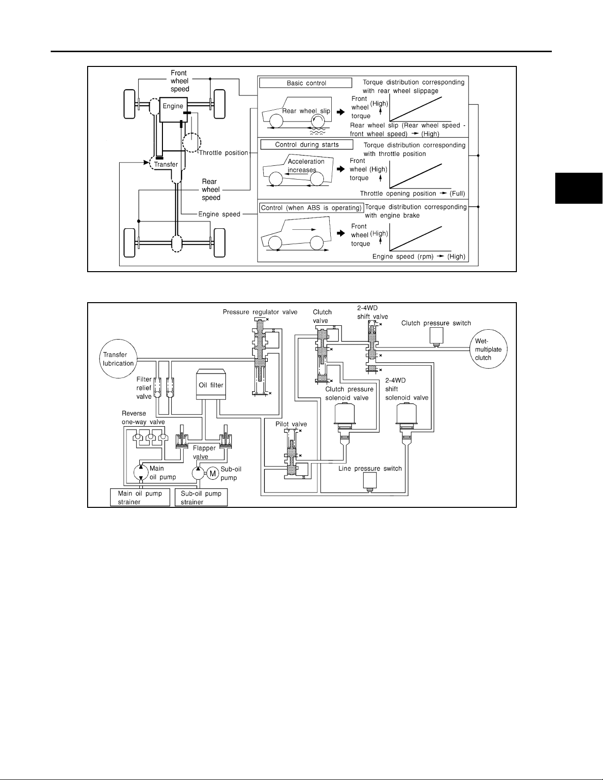
System Diagram INFOID:0000000001728333
WDIA0164E
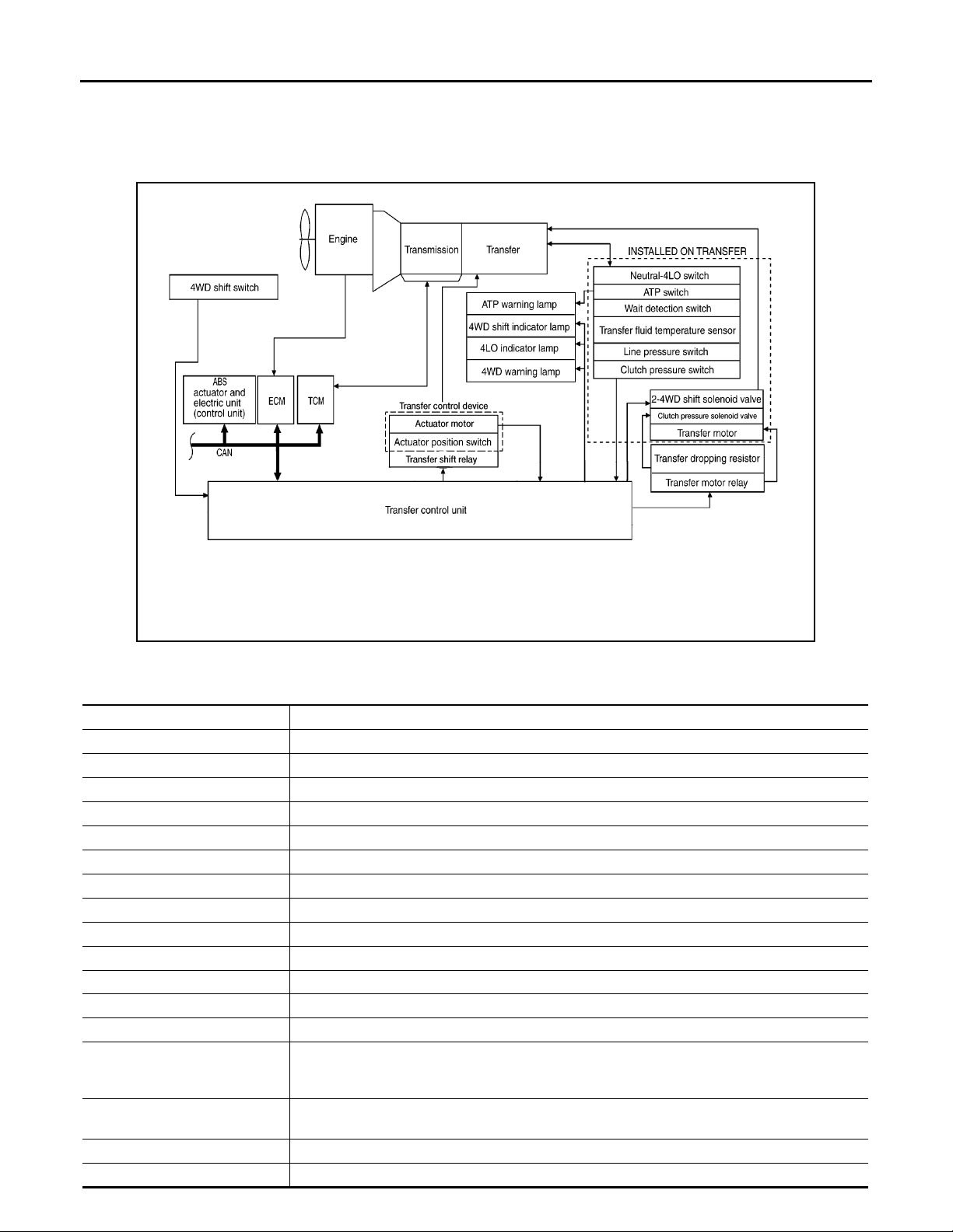
COMPONENT DESCRIPTION
Components Function
Transfer control unit Controls transfer control device, control valves and shifts between 2WD/4WD and 4H/4LO.
Transfer control device Integrates actuator motor and actuator position switch.
2-4WD shift solenoid valve Controls oil pressure and allows shifting between 2WD and 4WD.
Clutch pressure solenoid valve Controls oil pressure and distributes torque between front and rear tires.
Line pressure switch Detects line pressure.
Clutch pressure switch Detects clutch pressure.
Transfer fluid temperature sensor Detects transfer fluid temperature.
Actuator motor Moves shift rods when signaled by transfer control unit.
Actuator position switch Detects actuator motor position.
Wait detection switch Detects whether or not 4WD lock gear is locked.
4LO switch Detects if transfer case is in 4LO.
ATP switch Detects if transfer case is in neutral.
4WD shift switch Allows driver to select from 2WD/4WD, 4H/4LO and AUTO.
• Illuminates if malfunction is detected in 4WD system.
4WD warning lamp
ATP warning lamp
4WD shift indicator lamp Displays driving range selected by 4WD shift switch.
4LO indicator lamp Displays 4LO range.
• Flashes (1 flash / 2 seconds) if large difference in diameter of front and rear tires.
• Flashes (2 flashes / 1 second) if high transfer fluid temperature is detected.
Indicates that A/T parking mechanism does not operate when A/T selector lever is in P position
because transfer case is in neut ral.
DLN-12

< FUNCTION DIAGNOSIS >
4WD SYSTEM
[TRANSFER: ATX14B]
Components Function
ABS actuator and electric unit
(control unit)
TCM
ECM
Transmit s vehicle speed signal via CAN communication to transfer control unit.
Transmits the following signal via CAN communication to transfer control unit.
• Output shaft revolution signal
• A/T position indicator signal (PNP switch signal)
Transmits the following signals via CAN communication to transfer control unit.
• Engine speed signal
• Accelerator pedal position signal
System Description INFOID:0000000001728334
CONTROL SYSTEM
A
B
C
DLN
E
F
G
H
K
M
N
O
P
I
J
L
DLN-13

< FUNCTION DIAGNOSIS >
4WD SYSTEM
[TRANSFER: ATX14B]
ALL-MODE 4WD Transfer Basic Cont rol
SDIA3396E
DLN-14
< FUNCTION DIAGNOSIS >
4WD SYSTEM
[TRANSFER: ATX14B]
A
B
C
DLN
E
LDIA0055E
Hydraulic Control Circuits
WDIA0163E
TRANSFER CONTROL UNIT
• Transfer control unit controls transfer control device and it directs shifts from 4H-4LO and 2WD-4WD.
• Self-diagnosis can be done.
F
G
H
I
J
K
L
M
TRANSFER SHIFT HIGH AND LOW RELAYS
Transfer shift high and low relays apply power supply to transfer control device (actuator motor).
TRANSFER SHUT OFF RELAY
Transfer shut off relay applies power supply to transfer motor relay.
4WD SHIFT SWITCH AND INDICATOR LAMPS
4WD Shift Switch
Able to select from 2WD, AUTO, 4H or 4LO.
4WD Shift Indicator Lamp
• Displays driving conditions selected by 4WD shift switch with 2WD, AUTO and 4H indicators while engine is
running. (When 4WD warning lamp is turned on, all 4WD shift indicator lamps are turned off.)
• Turns ON for approximately 1 second when ignition switch is turned ON, for purpose of lamp check.
4LO Indicator Lamp
DLN-15
N
O
P

4WD SYSTEM
< FUNCTION DIAGNOSIS >
• Displays 4LO condition while engine is running. 4LO indicator lamp flashes if transfer gear does not shift
completely under 2WD, AUTO, 4H⇔4LO. (When 4WD warning lamp is turned on, 4LO indicator lamp is
turned off.)
• Turns ON for approximately 1 second when ignition switch is turned ON, for purpose of lamp check.
4WD WARNING LAMP
Turns on or flashes when there is a malfunction in 4WD system.
Also turns on when ignition switch is turned ON, for purpose of lamp check. Turns OFF approximately 1 second after the engine starts if system is normal.
4WD Warning Lamp Indication
Condition 4WD warning lamp
System normal OFF
Lamp check
4WD system malfunction ON
During self-diagnosis Flashes malfunction mode.
Large difference in diameter of front/
rear tires
High fluid temperature in transfer case
Turns ON when ignition switch is turned ON.
Turns OFF after engine start.
Flashes slow (1 flash / 2 seconds)
(Continues to flash until the ignition switch is turned OFF)
Flashes rapidly (2 flashes / 1 second)
(Continues to flash until fluid temperature returns to normal)
[TRANSFER: ATX14B]
ATP WARNING LAMP
When the A/T selector lever is in P position, the vehicle may move if the transfer case is in neutral. ATP warning lamp is turned on to indicate this condition to the driver.
LINE PRESSURE SWITCH
• With the transfer system design, control of the oil pressure provides the transmission of drive torque to the
front wheels. The main pressure to control the oil pressure is referred to as the line pressure.
• The line pressure switch determines whether or not adequate line pressure has built up under different operating conditions.
• The line pressure switch closes when line pressure is produced.
• The line pressure switch senses line pressure abnormalities and turns the 4WD warning lamp ON.
CLUTCH PRESSURE SWITCH
• The clutch pressure switch determines whether or not adequate clutch pressure has built up under different
operating conditions.
• The clutch pressure switch closes when clutch pressure is produced.
• The clutch pressure switch senses clutch pressure abnormalities and turns the 4WD warning lamp ON.
WAIT DETECTION SWITCH
• The wait detection switch operates when there is circulating torque produced in the propeller shaft (L→H) or
when there is a phase difference between 2-4 sleeve and clutch drum (H→L). After the release of the circulating torque, the wait detection switch helps provide the 4WD lock gear (clutch drum) shifts. A difference
may occur between the operation of the 4WD shift switch and actual drive mode. At this point, the wait
detection switch senses an actual drive mode.
• The wait detection switch operates as follows.
- 4WD lock gear (clutch drum) locked: ON
- 4WD lock gear (clutch drum) released: OFF
• The wait detection switch senses an actual drive mode and the 4WD shift indicator lamp indicates the vehicle drive mode.
ATP SWITCH
ATP switch detects if transfer case is in neutral by the position of the L-H shift fork.
NOTE:
Transfer case may be in neutral when shifting between 4H-4LO.
NEUTRAL-4LO SWITCH
The neutral-4LO switch detects that transfer gear is in neutral or 4LO (or shifting from neutral to 4LO) condition by L-H shift fork position.
DLN-16
4WD SYSTEM
< FUNCTION DIAGNOSIS >
TRANSFER FLUID TEMPERATURE SENSOR
The transfer fluid temperature sensor detects the transfer fluid temperature and sends a signal to the transfer
control unit.
[TRANSFER: ATX14B]
A
TRANSFER MOTOR
• The transfer motor drives the sub-oil pump to provide proper lubrication and oil pressure control when the
vehicle is at standstill, during low-speed operations or is being driven in reverse.
• The main oil pump is operated by the driving force of the mainshaft. In other words, sufficient oil pressure
buildup does not occur when the vehicle is at standstill or during low-speed operations. While the vehicle is
being driven in reverse, the main oil pump rotates in the reverse direction. Therefore the main oil pump does
not discharge oil pressure. During any of the above vehicle operations, the transfer motor drives the sub-oil
pump to compensate for insufficient oil pressure.
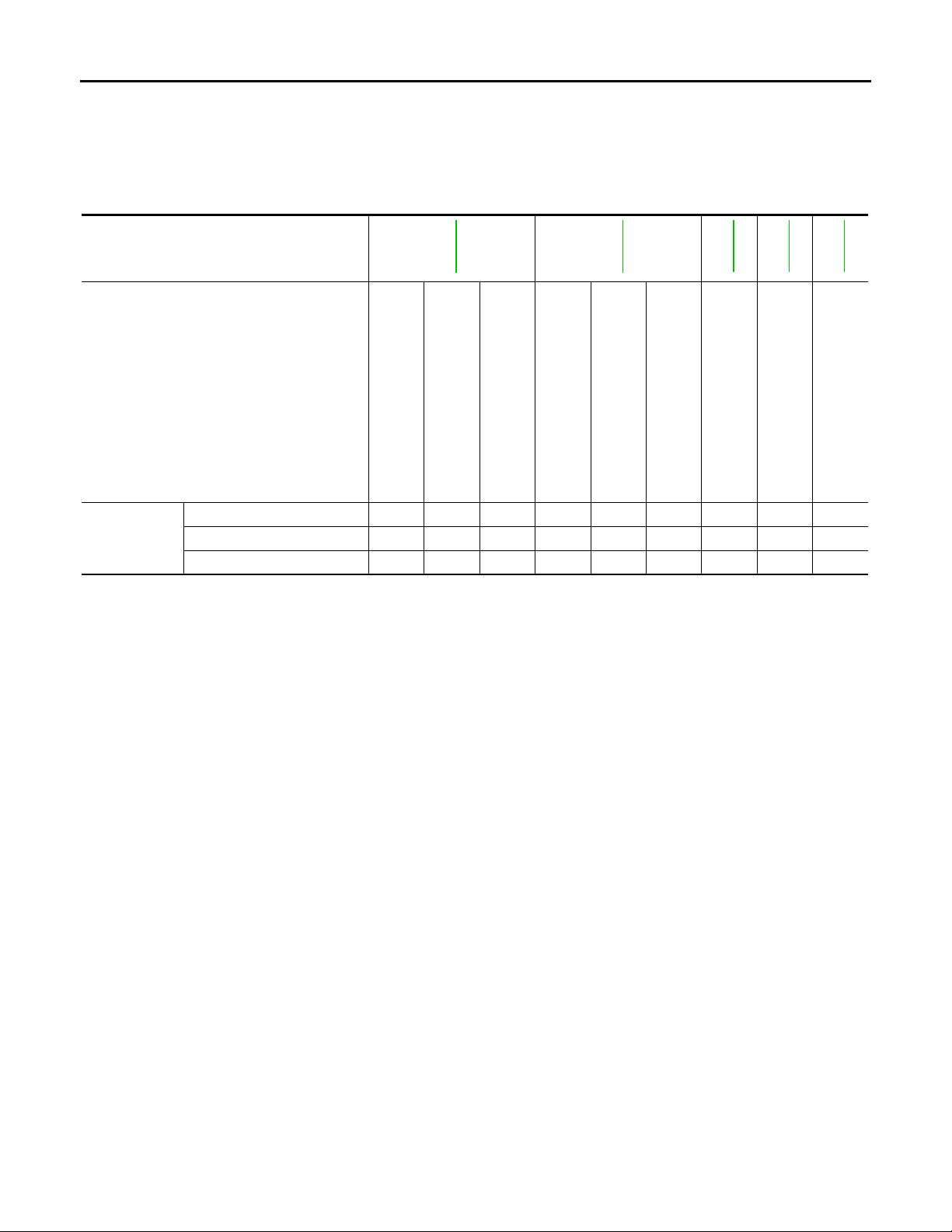
• The transfer motor operates as follows:
- The motor relay turns OFF in the 2WD mode.
- The motor relay operates as described in the table below in modes other than the 2WD mode.
• 4WD shift switch, PNP switch, Neutral-4LO switch, vehicle speed sensor and throttle position sensor are
used in conjunction with the transfer motor.
Transfer Motor Relay Operation
4WD shift switch A/T selector lever position
2WD — — — OFF
N position 0 — ON
P position 0
4H (LOCK) and 4LO
Other than R position
R position — — ON
R position — — ON
P or N position
AUTO
Other than R, P and N position
*: After 2.5 seconds have elapsed.
Vehicle speed
(VSS)
0 < VSS ≤ 50 km/h (31 MPH)
50 km/h (31 MPH) < VSS < 55
km/h (34 MPH)
55 km/h (34 MPH) ≤ VSS OFF
0
0 < VSS ≤ 50 km/h (31 MPH)
50 km/h (31 MPH) < VSS < 55
km/h (34 MPH)
55 km/h (34 MPH) ≤ VSS OFF
0 < VSS ≤ 50 km/h (31 MPH)
50 km/h (31 MPH) < VSS < 55
km/h (34 MPH)
55 km/h (34 MPH) ≤ VSS OFF
Accelerator pedal position
0 - 0.07/8 OFF*
0.07/8 - 1/8 HOLD
1/8 - MAX ON
—
0 - 0.07/8 OFF*
0.07/8 - 1/8 HOLD
1/8 - MAX ON
—
—
Motor relay drive
command
ON
HOLD
ON
HOLD
ON
HOLD
CLUTCH PRESSURE SOLENOID VALVE
The clutch pressure solenoid valve distributes front and rear torque in AUTO mode.
2-4WD SHIFT SOLENOID VALVE
The 2-4WD shift solenoid valve operates to apply oil pressure to the wet-multiplate clutch, depending on the
drive mode. The driving force is transmitted to the front wheels through the clutch so the vehicle is set in the
4WD mode. Setting the vehicle in the 2WD mode requires no pressure buildup. In other words, pressure force
applied to the wet-multiplate clutch becomes zero.
B
C
DLN
E
F
G
H
I
J
K
L
M
N
O
P
TRANSFER CONTROL DEVICE
Integrates actuator motor and actuator position switch.
DLN-17
4WD SYSTEM
< FUNCTION DIAGNOSIS >
Actuator Motor
Moves shift rods when signaled by transfer control unit.
Actuator Position Switch
Detects actuator motor position and then sends signal to transfer control unit.
[TRANSFER: ATX14B]
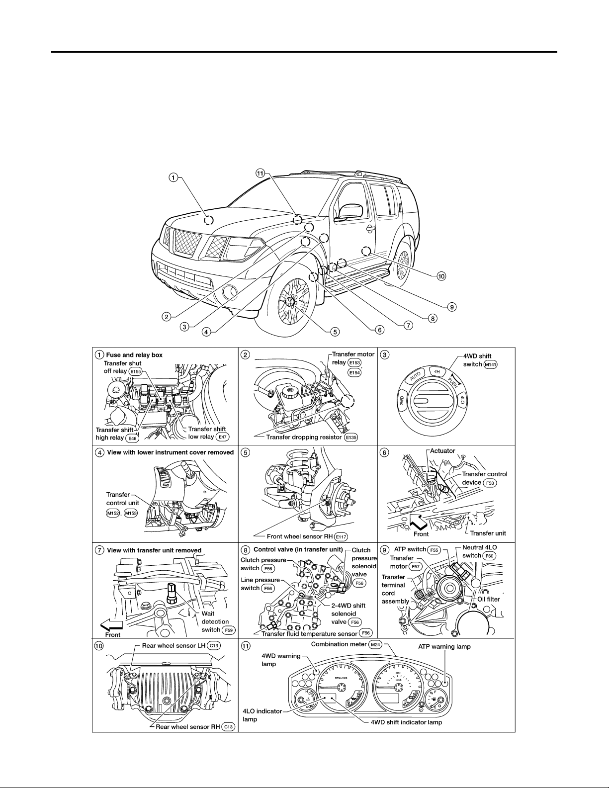
Component Parts Location INFOID:0000000001728335
DLN-18
WDIA0124E

4WD SYSTEM
< FUNCTION DIAGNOSIS >
[TRANSFER: ATX14B]
CAN Communication INFOID:0000000001728336
Refer to LAN-10, "Self-Diagnosis".
A
B
C
DLN
E
F
G
H
K
M
N
O
I
J
L
DLN-19
P

DIAGNOSIS SYSTEM (TRANSFER CONTROL UNIT)
< FUNCTION DIAGNOSIS >
[TRANSFER: ATX14B]
DIAGNOSIS SYSTEM (TRANSFER CONTROL UNIT)
CONSULT-III Function (ALL MODE AWD/4WD) INFOID:0000000001728337
FUNCTION
CONSULT-III can display each diagnostic item using the diagnostic test modes shown following.
ALL MODE AWD/4WD diag no sti c mod e Description
SELF-DIAG RESULTS Displays transfer control unit self-diagnosis results.
DATA MONITOR Displays transfer control unit input/output data in real time.
Supports inspections and adjustments. Commands are transmitted to the transfer control
WORK SUPPORT
CAN DIAG SUPPORT MNTR The results of transmit/receive diagnosis of CAN communication can be read.
ECU PAR T NUMBER Transfer control unit part number can be read.
SELF-DIAG RESULT MODE
Operation Procedure
1. Connect CONSULT-III.
2. With engine at idle, touch SELF-DIAG RESULTS.
Display shows malfunction experienced since the last erasing operation.
NOTE:
The details for TIME are as follows:
• 0: Error currently detected with transfer control unit.
• Except for 0: Error detected in the past and memorized with transfer control unit.
Detects frequency of driving after DTC occurs (frequency of turning ignition switch ON/OFF).
unit for setting the status suitable for required operation, input/output signals are received
from the transfer control unit and received data is displayed.
How to Erase Self-diagnostic Results
1. Perform applicable inspection of malfunctioning item and then repair or replace.
2. Start engine and select SELF-DIAG RESULTS mode for ALL MODE AWD/4WD with CONSULT-III.
3. Touch ERASE on CONSULT-III screen to erase DTC memory.
CAUTION:
If memory cannot be erased, perform applicable diagnosis.
SELF-DIAGNOSTIC PROCEDURE (WITHOUT CONSULT-III)
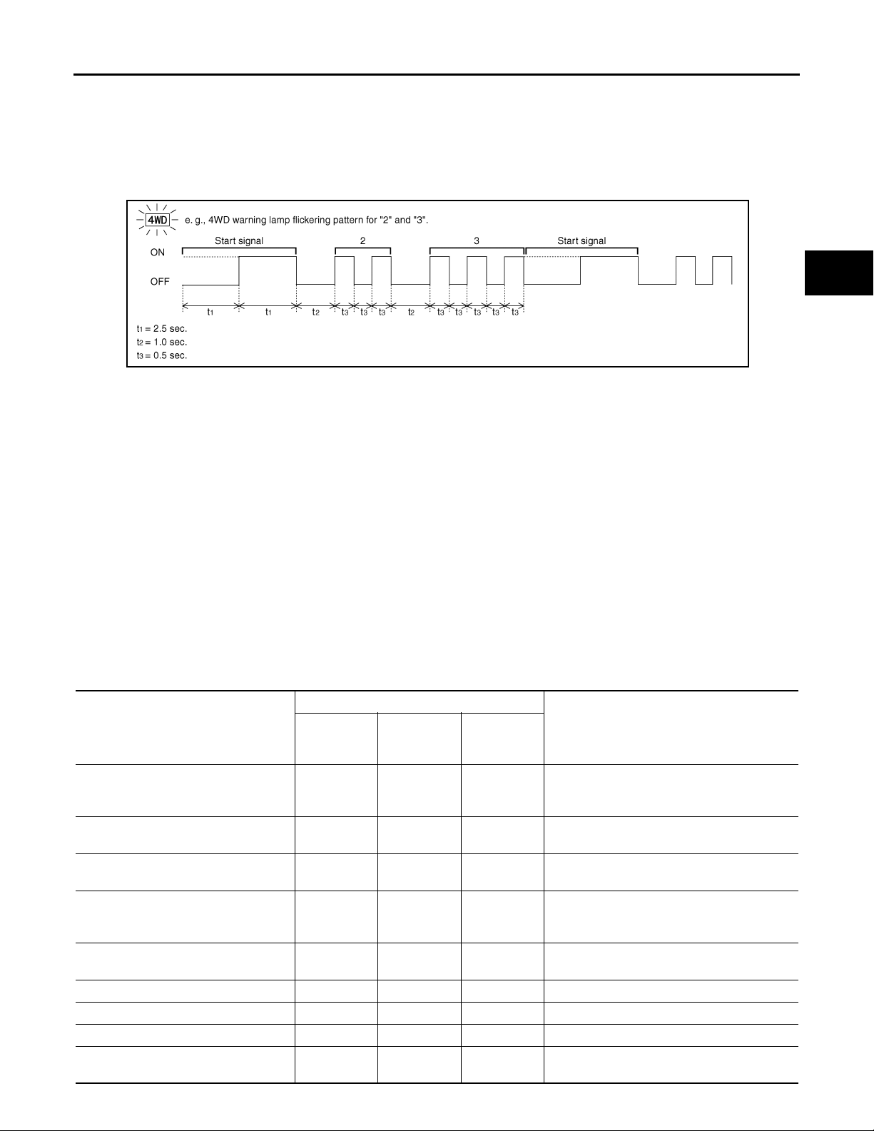
Description
If the engine starts when there is a malfunction in the 4WD system, the 4WD warning lamp turns ON or flickers
in the combination meter. When the system functions properly, the warning lamp turns ON when the ignition
switch is turned to ON, and it turns OFF after engine starts. To locate the cause of a malfunction, start the selfdiagnosis function. The 4WD warning lamp in the combination meter will indicate the malfunction area by
flashing according to the self-diagnostic results. Refer to DLN-101, "
Diagnostic Procedure
1. Warn up engine.
2. Move A/T selector lever to P position.
3. Turn 4WD shift switch to 2WD position.
4. Turn ignition switch ON and OFF at least twice, and then turn ignition switch OFF.
5. Turn 4WD shift switch to AUTO position.
6. Turn ignition switch ON. (Do not start engine.)
7. 4WD warning lamp ON.
8. Move A/T selector lever to R position.
9. Turn 4WD shift switch to 2WD, AUTO and 2WD in order.
10. Move A/T selector lever to D position.
11. Turn 4WD shift switch to 4H, AUTO and 4H in order.
DTC Index".
DLN-20
DIAGNOSIS SYSTEM (TRANSFER CONTROL UNIT)
< FUNCTION DIAGNOSIS >
12. Move A/T selector lever to N position.
13. Turn 4WD shift switch to AUTO position.
14. Move A/T selector lever to P position.
15. Read the flickering of 4WD warning lamp.
Self-diagnosis example
[TRANSFER: ATX14B]
A
B
C
DLN
E
PDIA0227E
ERASE SELF-DIAGNOSIS
• In order to make it easier to find the cause of hard-to-duplicate malfunctions, malfunction information is
stored into the control unit as necessary during use by the user. This memory is not erased no matter how
many times the ignition switch is turned ON and OFF.
• However, this information is erased by turning ignition switch OFF after performing self-diagnostics or by
erasing the memory using the CONSULT-III.
DATA MONITOR MODE
Operation Procedure
1. Connect CONSULT -III.
2. Touch DATA MONITOR.
3. Select from SELECT MONITOR ITEM, screen of data monitor mode is displayed.
NOTE:
When malfunction is detected, CONSULT-III performs REAL-TIME DIAGNOSIS.
Also, any malfunction detected while in this mode will be displayed at real time.
Display Item List
×: Standard –: Not applicable
Monitor item selection
Monitored item (Unit)
VHCL/S SEN·FR [km/h] or [mph] × – ×
VHCL/S SEN·RR [km/h] or [mph] × – ×
ENGINE SPEED [rpm] × – ×
THRTL POS SEN [V] × – ×
FLUID TEMP SE [V] × – ×
BATTERY VOLT [V] × – × Power supply voltage for transfer control unit.
2WD SWITCH [ON/OFF] × – × 4WD shift switch status is displayed.
AUTO SWITCH [ON/OFF] × – × 4WD shift switch status is displayed.
LOCK SWITCH [ON/OFF] × – ×
ECU INPUT
SIGNALS
MAIN
SIGNALS
SELEC-
TION FROM
MENU
Remarks
Wheel speed calculated by ABS actuator and
electric unit (control unit).
Signal input with CAN communication line.
Wheel speed calculated by TCM.
Signal input with CAN communication line.
Engine speed calculated by ECM.
Signal input with CAN communication line.
Accelerator pedal position (APP) sensor signal voltage is displayed.
Signal input with CAN communication line.
Transfer fluid temperature sensor signal voltage is displayed.
4WD shift switch status is displayed.
(LOCK means 4H of 4WD shift switch.)
F
G
H
I
J
K
L
M
N
O
P
DLN-21
DIAGNOSIS SYSTEM (TRANSFER CONTROL UNIT)
< FUNCTION DIAGNOSIS >
Monitor item selection
Monitored item (Unit)
4L SW [ON/OFF] × – ×
N POSI SW TF [ON/OFF] × – × Neutral-4LO switch signal status is displayed.
ATP SWITCH [ON/OFF] × – × ATP switch signal status is displayed.
WAIT DETCT SW [ON/OFF] × – × Wait detection switch status is displayed.
LINE PRES SW [ON/OFF] × – × Line pressure switch status is displayed.
CL PRES SW [ON / OFF] × – × Clutch pressure switch status is displayed.
N POSI SW AT [ON/OFF] × – ×
R POSI SW AT [ON/OFF] × – ×
P POSI SW AT [ON/OFF] × – ×
ABS OPER SW [ON/OFF] × – ×
VDC OPER SW [ON/OFF] × – ×
TCS OPER SW [ON/OFF] × – ×
THROTTLE POSI [0.0/8] – ××
4WD MODE [AUTO/LOCK/2WD/4L] – ××
VHCL/S COMP [km/h] or [mph] – ××
COMP CL TORQ [kgm] – ××
DUTY SOLENOID [%] – ××Control value of clutch pressure solenoid.
2-4WD SOL [ON/OFF] – ××Output condition to 2-4WD solenoid.
2-4WD SOL MON [ON/OFF] – – ×
MOTOR RELAY [ON/OFF] – ××
MOTOR RELAY MON [ON/OFF] – – ×
4WD FAIL LAMP [ON/OFF] – ××
2WD IND [ON/OFF] – – ×
AUTO IND [ON/OFF] – – ×
LOCK IND [ON/OFF] – – ×
4L IND [ON/OFF] – – ×
ECU INPUT
SIGNALS
MAIN
SIGNALS
SELEC-
TION FROM
MENU
4WD shift switch status is displayed.
(4L means 4LO of 4WD shift switch.)
N position signal of A/T PNP switch status is
displayed.
Signal input with CAN communication line.
R position signal of A/T PNP switch status is
displayed.
Signal input with CAN communication line.
P position signal of A/T PNP switch status is
displayed.
Signal input with CAN communication line.
ABS operation signal status is displayed.
Signal input with CAN communication line.
VDC operation signal status is displayed.
Signal input with CAN communication line.
TCS operation signal status is displayed.
Signal input with CAN communication line.
Thottle position status is displayed.
Signal input with CAN communication line.
Control status of 4WD recognized by transfer
control unit. (AUTO, 4H, 2WD or 4LO)
Vehicle speed recognized by transfer control
unit.
Calculated torque recognized by transfer control unit.
Check signal for transfer control u nit signal
output.
Transfer motor relay signal status is displayed.
Check signal for transfer control u nit signal
output.
Control status of 4WD warning lamp is displayed.
Control status of 4WD shift indicator lamp
(2WD indicator lamp) is displayed.
Control status of 4WD shift indicator lamp
(2WD and AUTO indicator lamp) is displayed.
Control status of 4WD shift indicator lamp
(2WD, AUTO and Lock indicator) is displayed.
Control status of 4LO indicator lamp is displayed.
[TRANSFER: ATX14B]
Remarks
DLN-22
DIAGNOSIS SYSTEM (TRANSFER CONTROL UNIT)
< FUNCTION DIAGNOSIS >
[TRANSFER: ATX14B]
Monitor item selection
Monitored item (Unit)
A TP IND [O N/OFF] – – ×
SHIFT POS SW1 [ON/OFF] × – ×
SHIFT POS SW2 [ON/OFF] × – ×
SHIFT ACT1 [ON/OFF] – ××Output condition to actuator motor (clockwise)
SHIFT AC MON1 [ON/OFF] × – ×
SHIFT ACT2 [ON/OFF] – ××
SHIFT AC MON2 [ON/OFF] × – ×
T/F F SPEED [km/h] or [mph] × – × Displayed, but do not use.
A/T R SPEED [km/h] or [mph] × – ×
AT GEAR POSI [1/2/3/4/5] × – × A/T actual gear position is displayed.
ECU INPUT
SIGNALS
MAIN
SIGNALS
SELEC-
TION FROM
MENU
Remarks
Control status of ATP warning lamp is displayed.
Actuator position switch 1 (Low) signal status
is displayed.
Actuator position switch 2 (high) signal status
is displayed.
Check signal for transfer control unit signal
output
Output condition to actuator motor (counterclockwise)
Check signal for transfer control unit signal
output
Output shaft revolution signal (Revolution
sensor) calculated by TCM.
Signal input with CAN communication line.
WORK SUPPORT
When there is no malfunction with transfer and 4WD system, the following symptoms in AUTO mode may be
claimed by a customer: vibration when accelerating on a low µ road (snow-covered or icy road) or a slight
shock is felt at a few hertz as if it were being pushed lightly from behind.
It is possible to deal with these symptoms by changing the CLUTCH FORCE RELEASE LIMIT VALUE. However, be careful when changing the value because it may adversely affect driving performance.
Operation Procedure
1. Connect CONSULT -III.
2. Touch WORK SUPPORT.
3. Select from CLUTCH/F RLS LIM ADJ, screen of data monitor mode is displayed.
A
B
C
DLN
E
F
G
H
I
J
K
Clutch Force Release Limit Adjustment
1. Initial CLUTCH FORCE RELEASE LIMIT value 0.3 kgm appears under CONDITION SETTING on CON-
SULT-III display.
1.2 kg-m : Tight corner braking symptom is alleviated.
However, vibration may occur when accelerating on a low µ road (icy road, etc.).
0.3 kg-m : Initial set value.
0.2 kg-m : Do not set to this value because the tight
corner braking symptom will get worse.
2. Touch 1.2 on the display.
3. Display changes to NOW ADJUSTING in a short time.
4. When clutch force release limit value is set to 1.2 kgm, current value 0.3 kgm shown on display will be
replaced by 1.2 kgm and ADJUSTMENT COMPLETE will appear at the same time. Clutch force release
limit value setting is now complete.
DLN-23
L
M
N
O
P
NOISE, VIBRATION AND HARSHNESS (NVH) TROUBLESHOOTING
< FUNCTION DIAGNOSIS >
[TRANSFER: ATX14B]
NOISE, VIBRATION AND HARSHNESS (NVH) TROUBLESHOOTING
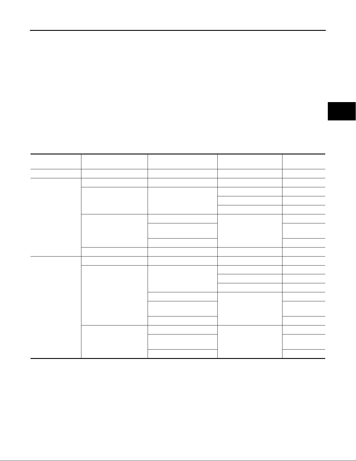
NVH Troubleshooting Chart INFOID:0000000001282210
Use the chart below to help you find the cause of the symptom. The numbers indicate the order of the inspection. If necessary, repair or replace these parts.
Reference page
SUSPECTED PARTS
(Possible cause)
DLN-132
DLN-149
DLN-149
DLN-149
DLN-149
Symptom
TRANSFER FLUID (Level low)
Noise 1 2 3 3
Transfer fluid leakage 31222
Hard to shift or will not shift 1 1 2
TRANSFER FLUID (Wrong)
TRANSFER FLUID (Level too high)
LIQUID GASKET (Damaged)
O-RING (Worn or damaged)
OIL SEAL (Worn or damaged)
SHIFT FORK (Worn or damaged)
GEAR (Worn or damaged)
BEARING (Worn or damaged)
DLN-24
P1811 POWER SUPPLY CIRCUIT FOR TRANSFER CONTROL UNIT
< COMPONENT DIAGNOSIS >
[TRANSFER: ATX14B]
COMPONENT DIAGNOSIS
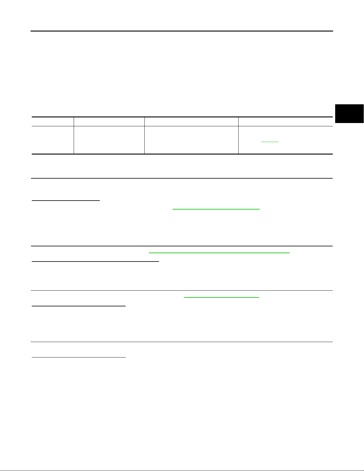
P1811 POWER SUPPLY CIRCUIT FOR TRANSFER CONTROL UNIT
Description INFOID:0000000001728338
Power supply to transfer control unit is abnormally low while driving.
DTC Logic INFOID:0000000001728339
DTC DETECTION LOGIC
DTC CONSULT-III Diagnostic item is detected when... Reference
[P1811] BATTERY VOLTAGE
DTC CONFIRMATION PROCEDURE
1.DTC CONFIRMATION PROCEDURE
1. Turn ignition switch ON.
2. Perform self-diagnosis.
Is DTC P1811 detected?
YES >> Perform diagnosis procedure. Refer to DLN-25, "Diagnosis Procedure".
NO >> Inspection End.
Diagnosis Procedure INFOID:0000000001728340
Power supply voltage fo r transfer control
unit is abnormally low while driving.
Refer to DLN-25
.
A
B
C
DLN
E
F
G
H
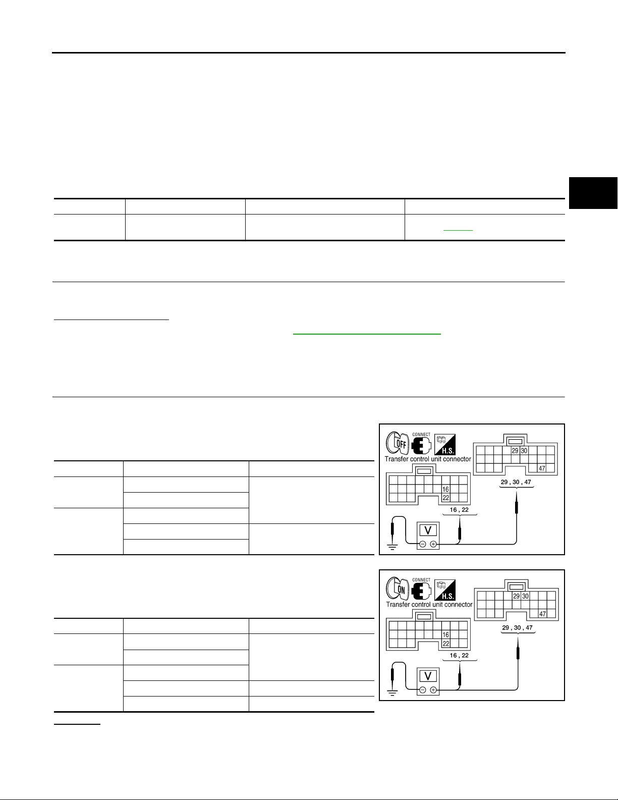
1.CHECK POWER SUPPLY
1. Turn ignition switch “OFF”. (Stay for at least 5 seconds.)
2. Connect transfer control unit harness connector.
3. Check voltage between transfer control unit harness connector
terminals and ground.
Connector Terminal Voltage (Approx.)
M152
M153
4. Turn ignition switch “ON”. (Do not start engine.)
5. Check voltage between transfer control unit harness connector
terminals and ground.
Connector Terminal Voltage (Approx.)
M152
M153
OK or NG
OK >> GO TO 2.
NG >> Check the following. If any items are damaged, repair or replace damaged parts.
• 10A fuses [No. 21 located in fuse block (J/B)] and No. 59 (located in the fuse and relay box).
16 - Ground
0V22 - Ground
29 - Ground
30 - Ground
47 - Ground
16 - Ground
29 - Ground
30 - Ground 0V
47 - Ground Battery voltage
Battery voltage
Battery voltage22 - Ground
WDIA0165E
WDIA0166E
I
J
K
L
M
N
O
P
DLN-25

P1811 POWER SUPPLY CIRCUIT FOR TRANSFER CONTROL UNIT
< COMPONENT DIAGNOSIS >
• Harness for short or open between battery and transfer control unit harness connector M153
terminals 47.
• Harness for short or open between ignition switch and transfer control unit harness connector
M153 terminal 29.
• Harness for short or open between battery and transfer shut off relay harness connector E155
terminal 1 and 3.
• Harness for short or open between transfer shut off relay harness connector E155 terminal 2
and transfer control unit harness connector M153 terminal 30.
• Harness for short or open between transfer shut off relay harness connector E155 terminal 5
and transfer control unit harness connector M152 terminals 16 and 22.
• Battery and ignition switch.
• Transfer shut off relay. Refer to DLN-26, "
Component Inspection".
2.CHECK GROUND CIRCUIT
1. Turn ignition switch “OFF”. (Stay for at least 5 seconds.)
2. Disconnect transfer control unit harness connector.
3. Check continuity between transfer control unit harness connector M152 terminals 3, 6, M153 terminal 45 and ground.
Continuity should exist.
Also check harness for short to power.
OK or NG
OK >> GO TO 3.
NG >> Repair open circuit or short to power in harness or con-
nectors.
3.CHECK TRANSFER CONTROL UNIT
[TRANSFER: ATX14B]
SDIA2691E
Check transfer control unit input/output signal. Refer to DLN-83, "
OK or NG
OK >> GO TO 4.
NG >> Check transfer control unit pin terminals for damage or loose connection with harness connector.
If any items are damaged, repair or replace damaged parts.
Reference Value".
4.CHECK DTC
Perform the self-diagnosis, after driving a vehicle for a while.
OK or NG
OK >> Inspection End.
NG >> Replace transfer control unit. Refer to DLN-135, "
Component Inspection INFOID:0000000001728341
1. Turn ignition switch OFF. (Stay for at least 5 seconds.)
2. Remove transfer shut off relay. Refer to DLN-18, "
3. Apply 12V direct current between transfer shut off relay terminals 1 and 2.
4. Check continuity between relay terminals 3 and 5.
Condition Continuity
12V direct current supply between terminals 1 and 2 Yes
OFF No
5. If inspection results are abnormal replace the transfer shut off
relay.
Component Parts Location".
Removal and Installation".
SCIA1245E
DLN-26
P1802 – P1804, P1809 TRANSFER CONTROL UNIT
< COMPONENT DIAGNOSIS >
[TRANSFER: ATX14B]
P1802 – P1804, P1809 TRANSFER CONTROL UNIT
Description INFOID:0000000001728342
The transfer control unit controls the transfer control device which controls shifts between AUTO, 4H and 4LO
and between 2WD and 4WD. A DTC may set when any of the following occur:
• Malfunction is detected in the memory (RAM) system of transfer control unit.
• Malfunction is detected in the memory (ROM) system of transfer control unit.
• Malfunction is detected in the memory (EEPROM) system of transfer control unit.
• AD converter system of transfer control unit is malfunctioning.
DTC Logic INFOID:0000000001728343
DTC DETECTION LOGIC
DTC CONSULT-III Diagnostic item is detected when... Reference
[P1802] CONTROL UNIT 1
[P1803] CONTROL UNIT 2
[P1804] CONTROL UNIT 3
[P1809] CONTROL UNIT 4
Malfunction is detected in the memory
(RAM) system of transfer control unit.
Malfunction is detected in the memory
(ROM) system of transfer control unit.
Malfunction is detected in the memory
(EEPROM) system of transfer control
unit.
AD converter system of transfer control
unit is malfunctioning.
Refer to DLN-27
.
A
B
C
DLN
E
F
G
H
DTC CONFIRMATION PROCEDURE
1.DTC CONFIRMATION PROCEDURE
1. Turn ignition switch ON.
2. Perform self-diagnosis.
Are DTC's P1802 - P1804 or P1809 detected?
YES >> Perform diagnosis procedure. Refer to DLN-27, "Diagnosis Procedure".
NO >> Inspection End.
Diagnosis Procedure INFOID:0000000001728344
1.INSPECTION START
Do you have CONSULT-III?
YES or NO
YES >> GO TO 2.
NO >> GO TO 3.
2.PERFORM SELF-DIAGNOSIS (WITH CONSULT-III)
With CONSULT-III
1. Turn ignition switch ON. (Do not start engine.)
2. Select SELF-DIAG RESULTS mode for ALL MODE AWD/4WD with CONSULT-III.
3. Touch ERASE.
4. Turn ignition switch OFF and wait at least 10 seconds.
5. Perform the self-diagnosis again.
Is the CONTROL UNIT 1 [P1802], CONTROL UNIT 2 [P1803], CONTROL UNIT 3 [P1804] or CONTROL
UNIT 4 [P1809] displayed?
YES >> Replace transfer control unit. Refer to DLN-135, "Removal and Installation".
NO >> Inspection End.
3.PERFORM SELF-DIAGNOSIS (WITHOUT CONSULT-III)
I
J
K
L
M
N
O
P
DLN-27

P1802 – P1804, P1809 TRANSFER CONTROL UNIT
< COMPONENT DIAGNOSIS >
Without CONSULT-III
1. Perform the self-diagnosis and then erase self-diagnostic results. Refer to DLN-20, "CONSULT-III Func-
tion (ALL MODE AWD/4WD)".
2. Perform the self-diagnosis again.
Do the self-diagnostic results indicate AD converter?
YES >> Replace transfer control unit.
NO >> Inspection End.
[TRANSFER: ATX14B]
DLN-28
P1807 VEHICLE SPEED SENSOR (A/T)
< COMPONENT DIAGNOSIS >
[TRANSFER: ATX14B]
P1807 VEHICLE SPEED SENSOR (A/T)
Description INFOID:0000000001728345
The transmission control module (TCM) transmits the output shaft revolution signal via CAN communication to
Transfer control unit. DTC P1807 will set when a malfunction is detected in the output shaft revolution signal
or an improper signal is input while driving.
DTC Logic INFOID:0000000001728346
DTC DETECTION LOGIC
DTC CONSULT-III Diagnostic item is detected when... Reference
• Malfunction is detected in output shaft
[P1807] VHCL SPEED SEN·AT
DTC CONFIRMATION PROCEDURE
revolution signal that is output from
TCM through CAN communication.
• Improper signal is input while driving.
Refer to DLN-29
.
1.DTC CONFIRMATION PROCEDURE
1. Turn ignition switch ON.
2. Perform self-diagnosis.
Is DTC P1807 detected?
YES >> Perform diagnosis procedure. Refer to DLN-29, "Diagnosis Procedure".
NO >> Inspection End.
A
B
C
DLN
E
F
G
H
Diagnosis Procedure INFOID:0000000001728347
1.CHECK DTC WITH TCM
Perform self-diagnosis with TCM. Refer to TM-35, "
Is any malfunction detected by self-diagnosis?
YES >> Check the malfunctioning system.
NO >> GO TO 2.
CONSULT-III Function (TRANSMISSION)".
2.CHECK TRANSFER CONTROL UNIT
Check transfer control unit input/output signal. Refer to DLN-83, "
Are the inspection results normal?
YES >> GO TO 3.
NO >> Check transfer control unit pin terminals for damage or loose connection with harness connector.
If any items are damaged, repair or replace damaged parts.
Reference Value".
3.CHECK DTC
Drive the vehicle and then perform self-diagnosis.
Are the inspection results normal?
YES >> Inspection End.
NO >> Perform self-diagnosis with TCM again.
I
J
K
L
M
N
O
DLN-29
P

P1808 VEHICLE SPEED SENSOR (ABS)
< COMPONENT DIAGNOSIS >
[TRANSFER: ATX14B]
P1808 VEHICLE SPEED SENSOR (ABS)
Description INFOID:0000000001728348
The ABS actuator and electric unit (control unit) transmits a vehicle speed signal via CAN communication to
the transfer control unit. DTC P1808 sets when a malfunction is detected in the vehicle speed signal that is
output from the ABS actuator and electric unit (control unit) or an improper signal is input while driving.
DTC Logic INFOID:0000000001728349
DTC DETECTION LOGIC
DTC CONSULT-III Diagnostic item is detected when... Reference
• Malfunction is detected in vehicle
speed signal that is outpu t from ABS
[P1808] VHCL SPEED SEN·ABS
DTC CONFIRMATION PROCEDURE
actuator and electric unit (control unit)
through CAN communication.
• Improper signal is input while driving.
Refer to DLN-30
.
1.DTC CONFIRMATION PROCEDURE
1. Turn ignition switch ON.
2. Perform self-diagnosis.
Is DTC P1808 displayed?
YES >> Perform diagnosis procedure. Refer to DLN-30, "Diagnosis Procedure".
NO >> Inspection End.
Diagnosis Procedure INFOID:0000000001728350
1.CHECK DTC WITH ABS ACTUATOR AND ELECTRIC UNIT (CONTROL UNIT)
Perform self-diagnosis with ABS actuator and electric unit (control unit). Refer to BRC-141, "
Function (ABS)".
Is any malfunction detected by self-diagnosis?
YES >> Check the malfunctioning system.
NO >> GO TO 2.
CONSULT-III
2.CHECK TRANSFER CONTROL UNIT
Check transfer control unit input/output signal. Refer to DLN-83, "
Are the inspection results normal?
YES >> GO TO 3.
NO >> Check transfer control unit pin terminals for damage or loose connection with harness connector.
If any items are damaged, repair or replace damaged parts.
Reference Value".
3.CHECK DTC
Perform the self-diagnosis, after driving a vehicle for a while.
Are the inspection results normal?
YES >> Inspection End.
NO >> Perform self-diagnosis with ABS actuator and electric unit (control unit) again.
DLN-30
 Loading...