

Page 1

B ENGINE
A
ACC
SECTION
ACCELERATOR CONTROL SYSTEM
CONTENTS
PRECAUTIONS .......................................................... 2
Precautions for Supplemental Rest raint System
(SRS) “AIR BAG” and “SEAT BELT PRE-TEN-
SIONER” .................................................................. 2
ACCELERATOR CONTROL SYSTEM ...................... 3
Components ................................ ............................. 3
Removal and Installation .......................................... 4
REMOVAL FOR ADJUSTABLE ACCELERATOR
PEDAL ............................ .......................... ............. 4
REMOVAL FOR NON-ADJUSTABLE ACCEL-
ERATOR PEDAL ............................................. ...... 5
INSTALLATION .....................................................5
INSPECTION AFTER INSTALLATION ..................5
SERVICE DATA AND SPECIFICATIONS (SDS) ........6
Accelerator Control ...................................................6
ADJUSTABLE AND NON-ADJUSTABLE
ACCELERATOR PEDAL .......................................6
C
D
E
F
G
H
I
J
K
M
L
Revision: September 2005 2006 Pathfinder
ACC-1
Page 2

PRECAUTIONS
PRECAUTIONS PFP:00001
Precautions for Supplemental Restraint System (SRS) “AIR BAG” and “SEA T
BELT PRE-TENSIONER”
The Supplemental Restraint System such as “AIR BAG” and “SEAT BELT PRE-TENSIONER”, used along
with a front sea t belt , helps t o redu ce th e r isk or s everi ty of injury to th e driv er an d front passenge r for c ertain
types of collisi on . Thi s s ys te m in cludes seat belt swi tch inp uts an d dual stage front air bag mod ul es . The SRS
system uses the seat belt switches to determine the front air bag deployment, and may only deploy one front
air bag, depending on the severity of a collision and whether the front occupants are belted or unbelted.
Information ne ce ss ary t o se rvi ce th e sy stem saf e ly is i nclu de d in th e SR S and SB se ct i on of th is Ser vic e Manual.
WARNING:
● To avoid rendering the SRS inoperativ e, which cou ld increase the risk of persona l injury or death
in the event of a collision which would result in air bag inflation, all maintenance must be performed by an authorized NISSAN/INFINITI dealer.
● Improper maintenance, in cluding incorrect removal a nd installation of the SRS, can lead to per-
sonal injury caused by unintentional activation of the system. For rem ova l of Sp iral Cable and Air
Bag Module, see the SRS section.
● Do not use electrical test equipme nt on any circuit related to the SRS unle ss instructed to in this
Service Manual. SRS wiring harnesses can be identified by yellow and/or orange harnesses or
harness connectors .
EBS00T2F
Revision: September 2005
ACC-2
2006 Pathfinder
Page 3
ACCELERATOR CONTROL SYSTEM
ACCELERATOR CONTROL SYSTEM PFP:18005
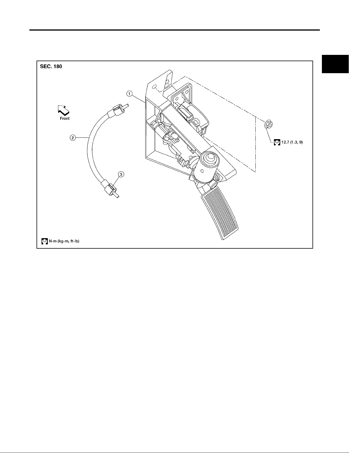
Components EBS00QUL
Adjustable Accelerator Pedal
A
ACC
C
D
E
F
G
WBIA0628E
1. Adjustable accelerator pedal assembly 2. Adjustable brake pedal cable 3. Adjustable brake pedal cable lock
tab (part of the cable)
H
I
J
K
L
M
Revision: September 2005 2006 Pathfinder
ACC-3
Page 4
ACCELERATOR CONTROL SYSTEM
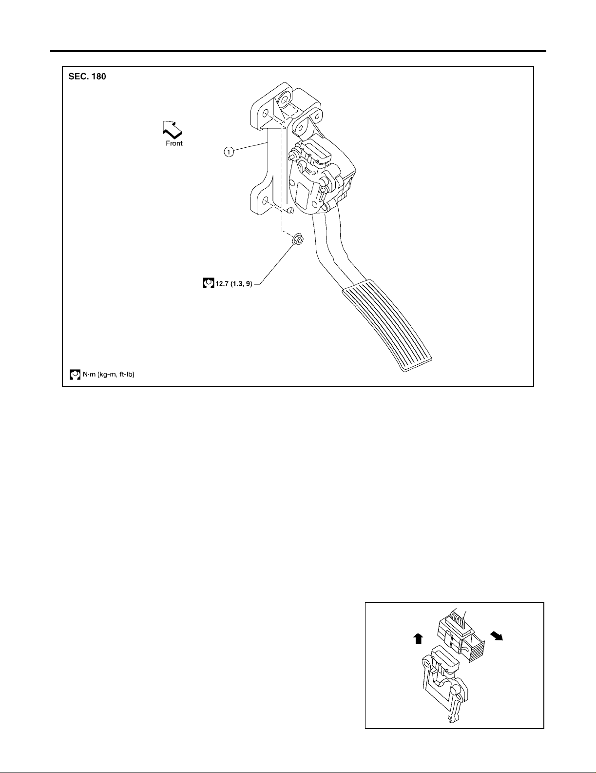
Non-adjustable Accelerator Pedal
WBIA0629E
1. Non-adjustable accelerator pedal assembly
CAUTION:
● Before removal and installation, the adjustable accele rator and brak e pedals mus t be in the front-
most position, if equipped. This is to align the base position of the accelerator and brake pedals.
● Do not disassemble the accelerator pedal assembly.
● Do not remove the accelerator pedal position sensor from the accelerator pedal bracket.
● Do not disassemble the accelerator pedal adjusting mechanism.
● Avoid damage from dropping the accelerator pedal assembly during handling.
● Keep the acce lerator pedal assembly away from water.
Removal and Installation EBS00QUM
REMOVAL FOR ADJUSTABLE ACCELERATOR PEDAL
1. Move the accelerator and brake pedals to the frontmost position.
2. Tur n the ignition switch OFF and disconnect the negative battery terminal.
3. Disconnect the adjustable pedal electric motor electrical connector.
4. Disconnect the adjustable pedal electric motor memory electrical connector, if equipped .
5. Disconnect the accelerator position sensor electrical connector.
a. Pull the connector lock back to unlock the connector from the
accelerator pedal position sensor as shown.
b. Pull up on the connector to disconnect it from the accelerator
pedal position sensor as shown.
Revision: September 2005
ACC-4
LBIA0333E
2006 Pathfinder
Page 5
ACCELERATOR CONTROL SYSTEM
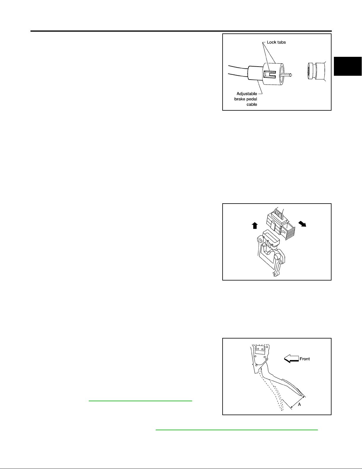
6. Disconnect the adjustable brake pedal cable from the adjustable
accelerator pedal.
● Release the two lock tabs, then pull the adjustable brake
pedal cable to disconnect it from the adjustable accelerator
pedal.
7. Remove the two upper and one lower accelerator pedal nuts.
8. Remove the adjustable accelerator pedal assembly.
CAUTION:
● Do not disassemble the accelerator pedal assembly.
● Do not remove the accelerator pedal position sensor from the accelerator pedal bracket.
● Do not disassemble the accelerator pedal adjusting mechanism.
● Avoid damage from dropping the accelerator pedal assembly during handling.
● Keep the accelerator pedal assembly away from water.
REMOVAL FOR NON-ADJUSTABLE ACCELERA TOR PEDAL
1. Disconn ect the ne ga tiv e ba tte ry term in al.
2. Disconnect the accelerator position sensor electrical connector.
a. Pull the connector lock back to unlock the connector from the
accelerator pedal position sensor as shown.
b. Pull up on the connector to disconnect it from the accelerator
pedal position sensor as shown.
3. Remove the two upper and one lower accelerator pedal nuts.
4. Remove the acceler ator pedal assembly.
CAUTION:
● Do not disassemble the accelerator pedal assembly.
● Do not remove the accelerator pedal position sensor
from the accelerator pedal bracket.
● Avoid damage from dropping the accelerator pedal assembly during handling.
● Keep the accelerator pedal assembly away from water.
LFIA0233E
LBIA0333E
A
ACC
C
D
E
F
G
H
I
J
K
L
INSTALLATION
Installation is in the reverse order of removal.
INSPECTION AFTER INSTALLATION
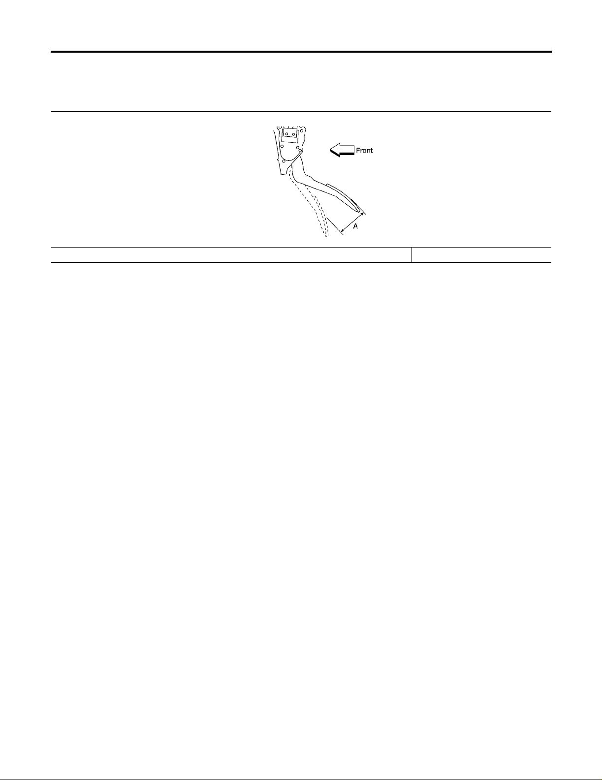
● Check that the accelerator pedal moves smoothly within the
specified range.
Accelerator pedal - total pedal
applied stroke “A”
● Check that the accelerator pedal smoothly returns to the original
position.
● Perform an elect ric al in sp ecti on of th e acce le r ato r pedal po si t ion
sensor. Refer to EC-602, "
DTC P2138 APP SENSOR" .
CAUTION:
When the harness connector of the accelerator pedal position sensor is disconnected, perform ″Accelerator Pedal
Released Position Learning″. Refer to EC-77, "
Revision: September 2005 2006 Pathfinder
: 48 mm (1.89 in)
LBIA0434E
Accelerator Pedal Released Position Learning" .
ACC-5
M
Page 6
SERVICE DATA AND SPECIFICATIONS (SDS)
SERVICE DATA AND SPECIFICATIONS (SDS) PFP:00030 Accelerator Control EBS00QUN
ADJUSTABLE AND NON-ADJUSTABLE ACCELERATOR PEDAL
Unit: mm (in)
LBIA0434E
Accelerator pedal - total pedal applied stroke “A” 48 (1.89)
Revision: September 2005
ACC-6
2006 Pathfinder
 Loading...