

Nissan Pathfinder 2008 User Manual

VENTILATION, HEATER & AIR CONDITIONER
SECTION HAC
A
B
HEATER & AIR CONDITIONING CONTROL SYSTEM
CONTENTS
AUTOMATIC AIR CONDITIONER
BASIC INSPECTION ....................................
DIAGNOSIS AND REPAIR WORKFLOW ..........4
How to Perform Trouble Diagnosis For Quick And
Accurate Repair ........................................................
INSPECTION AND ADJUSTMENT ..................... 5
Operational Check (Front) .........................................5
Operational Check (Rear) .........................................6
FUNCTION DIAGNOSIS ...............................8
FUNCTION INFORMATION ................................8
Component Part Location ...................... ...................8
Symptom Table .......................................................11
REFRIGERATION SYSTEM ..............................13
Refrigerant Cycle ....................................................13
Refrigerant System Protection ................................13
AUTOMATIC AIR CONDITIONER SYSTEM .....14
Control System Diagram .........................................14
Control System Description .....................................14
Discharge Air Flow (Front) ......................................17
Switches And Their Control Function (Front) ..........18
Switches And Their Control Function (Rear) ...........19
CAN COMMUNICATION SYSTEM ....................20
System Description .................................................20
DIAGNOSIS SYSTEM (HVAC) ..........................21
CONSULT-III Function (HVAC) ...............................21
COMPONENT DIAGNOSIS .........................25
MODE DOOR MOTOR ......................................25
4
System Description ..................................................25
Mode Door Motor (Front) Component Function
4
Check ......................................................................
Mode Door Motor (Front) Diagnosis Procedure ......27
AIR MIX DOOR MOTOR ...................................31
System Description ..................................................31
Air Mix Door Motor Component Function Check .....32
Air Mix Door Motor (Driver) Diagnosis Procedure ....33
Air Mix Door Motor (Passenger) Diagnosis Proce-
dure .........................................................................
INTAKE DOOR MOTOR ...................................41
System Description ..................................................41
Intake Door Motor Component Function Check ......42
Intake Door Motor Diagnosis Procedure .................43
BLOWER MOTOR CONTROL SYSTEM ..........45
System Description ..................................................45
Front Blower Motor Component Function Check ....46
Front Blower Motor Diagnosis Procedure ................47
Front Blower Motor Component Inspection .............50
Rear Blower Motor Description ................................51
Rear Blower motor Component Function Check .....52
Rear Air Control (Front) Diagnosis Procedure #1 ....53
Rear Air Control (Rear) Diagnosis Procedure #2 ....54
Rear Air Control (Rear) Diagnosis Procedure #3 ....55
Rear Air Control (Rear) Diagnosis Procedure #4 ....58
Rear Blower Motor And Relay Component Inspec-
tion ................................ ................................... ........
26
37
59
C
D
E
F
G
H
HAC
J
K
L
M
N
O
DIAGNOSIS SYSTEM (BCM) ............................22
CONSULT-III Function (BCM) .................................22
SELF-DIAGNOSIS FUNCTION ..........................23
A/C Auto Amp. Self-Diagnosis ................................23
A/C and AV Switch Assembly Self-Diagnosis .........23
A/C System Self-Diagnosis Code Chart ..................24
HAC-1
REAR AIR CONTROL SYSTEM .......................61
Rear Air Control System Description .......................61
Rear Air Control Component Function Check .........61
Rear Air Control (Front) Diagnosis Procedure .........62
Rear Air Control (Rear) Diagnosis Procedure .........64
MAGNET CLUTCH ...........................................67
System Description ..................................................67
P

Magnet Clutch Component Function Check ........... 67
Magnet Clutch Diagnosis Procedure ...................... 68
MEMORY FUNCTION DOES NOT OPERAT E ..119
Memory Function Check ....................................... 119
WATER VALVE CIRCUIT ..................................72
Water Valve Description (VK56DE) ........................ 72
Water Valve Diagnosis Procedure (VK56DE) ......... 72
HEATER PUMP ................................................. 74
System Description (VQ40DE) ............................... 74
Diagnosis Procedure (VQ40DE) ............................. 74
Component Inspection (VQ40DE) .......................... 76
AMBIENT SENSOR ........................................... 77
Component Description .......................................... 77
Ambient Sensor Diagnosis Procedure .................... 77
Ambient Sensor Component Inspection ................. 78
IN-VEHICLE SENSOR ....................................... 80
Component Description .......................................... 80
In-Vehicle Sensor Diagnosis Procedure ................. 80
In-Vehicle Sensor Component Inspection .............. 82
OPTICAL SENSOR ........................................... 83
Component Description .......................................... 83
Optical Sensor Diagnosis Procedure ...................... 83
INTAKE SENSOR .............................................. 85
System Description .......................... .... ... ... ... .......... 85
Intake Sensor Diagnosis Procedure ....................... 85
Intake Sensor Component Inspection .................... 86
PRECAUTION ...........................................120
PRECAUTIONS ................................................120
Supplemental Restraint System (SRS) "AIR BAG"
and "SEAT BELT PRE-TENSIONER" ..................
Working with HFC-134a (R-134a) ......................... 120
Precaution for Service Equipment ........................ 121
120
MANUAL AIR CONDITIONER
BASIC INSPECTION .................................122
DIAGNOSIS AND REPAIR WORKFLOW ........122
How to Perform Trouble Diagnosis For Quick And
Accurate Repair ..................... .... ... ........................
122
INSPECTION AND ADJUSTMENT ..................123
Operational Check ................................................ 123
FUNCTION DIAGNOSIS ...........................125
FUNCTION INFORMATION .............................125
Component Part Location ..................................... 125
Symptom Table ..................................................... 127
REFRIGERATION SYSTEM .............................128
Refrigerant Cycle .................................................. 128
Refrigerant System Protection .............................. 128
POWER SUPPLY AND GROUND CIRCUIT
FOR CONTROLLER ..........................................
Component Description .......................................... 87
A/C Auto Amp. Component Function Check .......... 87
A/C Auto Amp Power and Ground Diagnosis Pro-
cedure ........................... .......................... ................
87
88
ECU DIAGNOSIS ........................................ 89
AIR CONDITIONER CONTROL ........................89
A/C Auto Amp. Terminals Reference Values ......... 89
Wiring Diagram ....................................................... 91
SYMPTOM DIAGNOSIS ............................106
AIR CONDITIONER CONTROL ...................... 106
Symptom Matrix Chart .........................................106
INSUFFICIENT COOLING ............................... 107
Component Function Check ..................................107
Performance Test Diagnoses ........................... .....108
Performance Chart . ... ... ... ......................................110
Test Reading .........................................................111
Trouble Diagnoses for Unusual Pressure ..............112
INSUFFICIENT HEATING ............................... 115
Component Function Check ..................................115
NOISE .............................................................. 117
Component Function Check ..................................117
MANUAL AIR CONDITIONER SYSTEM .........129
Control System Diagram ....................................... 129
Control System Description .................................. 129
Discharge Air Flow ................................................ 131
Switches And Their Control Function .................... 131
CAN COMMUNICATION SYSTEM ..................133
System Description ............................................... 133
DIAGNOSIS SYSTEM (BCM) ...........................134
CONSULT-III Function (BCM) ......................... ... .. 134
COMPONENT DIAGNOSIS ......................135
MODE DOOR MOTOR .....................................135
System Description ............................................... 135
Mode Door Motor (Front) Component Funct ion
Check ............................... .....................................
Mode Door Motor (Front) Diagnosis Procedure .... 136
AIR MIX DOOR MOTOR ..................................139
System Description ............................................... 139
Air Mix Door Motor Component Function Check .. 140
Air Mix Door Motor Diagnosis Procedure .............. 141
INTAKE DOOR MOTOR ...................................143
System Description ............................................... 143
Intake Door Motor Component Function Check .... 143
Intake Door Motor Diagnosis Procedure ............... 144
BLOWER MOTOR ............................................146
135
HAC-2

System Description ...............................................
Front Blower Motor Component Function Check ..146
Front Blower Motor Diagnosis Procedure . ... .... .....147
Front Blower Motor Component Inspection ...........151
146
MAGNET CLUTCH ...........................................152
System Description ...............................................152
Magnet Clutch Component Function Check .........152
Magnet Clutch Diagnosis Procedure .....................152
INTAKE SENSOR ............................................157
System Description ...............................................157
Intake Sensor Diagnosis Procedure ......................157
Intake Sensor Component Inspection ...................158
POWER SUPPLY AND GROUND CIRCUIT
FOR CONTROLLER ........................................
Component Description ................................ .... .....159
Front Air Control Component Function Check ......159
Front Air Control Power and Ground Diagnosis
Procedure ..................... ................ ................ .........
159
160
ECU DIAGNOSIS .......................................161
AIR CONDITIONER CONTROL .......................161
System Description ...............................................161
System Operation .................................................161
Front Air Control Terminals Reference Values .....162
Wiring Diagram ......................................................164
SYMPTOM DIAGNOSIS ............................171
AIR CONDITIONER CONTROL ......................171
Symptom Matrix Chart .........................................171
INSUFFICIENT COOLING ..............................172
Component Function Check ..................................172
Performance Test Diagnoses ................................173
Performance Chart ................................................175
Test Reading ......................................... ................176
Trouble Diagnoses for Unusual Pressure ..............177
INSUFFICIENT HEATING ...............................181
Component Function Check ..................................181
NOISE ..............................................................183
Component Function Check ..................................183
PRECAUTION ............................................185
PRECAUTIONS ...............................................185
Supplemental Restraint System (SRS) "AIR BAG"
and "SEAT BELT PRE-TENSIONER" ...................
Working with HFC-134a (R-134a) ................... ... ...185
Precaution for Service Equipment .........................186
185
A
B
C
D
E
F
G
H
HAC
J
K
L
M
N
O
P
HAC-3

DIAGNOSIS AND REPAIR WORKFLOW
< BASIC INSPECTION >
[AUTOMATIC AIR CONDITIONER]
BASIC INSPECTION
DIAGNOSIS AND REPAIR WORKFLOW
How to Perform Trouble Diagnosis For Quick And Accurate Repair INFOID:0000000001366682
WORK FLOW
1.LISTEN TO CUSTOMER COMPLAINT
Listen to customer complaint. Get detailed information about the conditions and environment when the symptom occurs.
>> GO TO 2
2.CHECK FOR SERVICE BULLETINS
Check for any service bulletins.
>> GO TO 3.
3.VERIFY THE SYMPTOM WITH OPERATIONAL CHECK
Verify the symptom with operational check. Refer to HAC-123, "
Can a symptom be duplicated?
YES >> GO TO 4
NO >> GO TO 5
4.GO TO APPROPRIATE TROUBLE DIAGNOSIS
Go to appropriate trouble diagnosis. Refer to HAC-171, "
Can a symptom be duplicated?
>> GO TO 5.
Symptom Matrix Chart".
5.PERFORM THE A/C AUTO AMP SELF-DIAGNOSIS
Perform A/C auto amp. self-diagnosis. Refer to HAC-23, "
>> If any diagnostic trouble codes set. Refer to HAC-24, "
>> Confirm the repair by performing operational check. Refer to HAC-123, "
A/C Auto Amp. Self-Diagnosis".
Operational Check".
A/C System Self-Diagnosis Code Chart".
Operational Check".
HAC-4

< BASIC INSPECTION >
INSPECTION AND ADJUSTMENT
[AUTOMATIC AIR CONDITIONER]
INSPECTION AND ADJUSTMENT
Operational Check (Front) INFOID:0000000001366683
The purpose of the operational check is to confirm that the system operates properly.
Conditions : Engine running and at normal operating temperature
CHECKING MEMORY FUNCTION
1. Set the temperature to 32°C (90°F).
2. Press the OFF switch.
3. Turn ignition switch OFF.
4. Turn ignition switch ON.
5. Press the AUTO switch.
6. Confirm that the set temperature remains at previous temperature.
7. Press the OFF switch.
If NG, go to trouble diagnosis procedure for HAC-119, "
If OK, continue with next check.
CHECKING BLOWER
1. Press the blower speed control switch (+) once, blower should operate on low speed. The fan display
should have one bar lit (on display).
2. Press the blower speed control switch (+) again, and continue checking blower speed and fan display until
all speeds are checked.
3. Leave blower on maximum speed.
If NG, go to trouble diagnosis procedure for HAC-147, "
If OK, continue with next check.
Memory Function Check".
Front Blower Motor Diagnosis Procedure".
A
B
C
D
E
F
G
H
HAC
CHECKING DISCHARGE AIR
1. Press MODE switch four times and the DEF switch.
2. Each position indicator should change shape (on display).
3. Confirm that discharge air comes out according to the air distribution table. Refer to HAC-17, "
Air Flow (Front)"
Mode door position is checked in the next step.
If NG, go to trouble diagnosis procedure for HAC-136, "
If OK, continue the check.
NOTE:
Confirm that the compressor clutch is engaged (sound or visual inspection) and intake door position is at
fresh when the FOOT, DEF or D/F is selected.
Mode Door Motor (Front) Diagnosis Procedure".
Discharge
CHECKING RECIRCULATION ( , ONLY)
1. Press recirculation ( ) switch one time. Recirculation indicator should illuminate.
2. Press recirculation ( ) switch one more time. Recirculation indicator should go off.
3. Listen for intake door position change (blower sound should change slightly).
If NG, go to trouble diagnosis procedure for HAC-144, "
If OK, continue the check.
NOTE:
Confirm that the compressor clutch is engaged (sound or visual inspection) and intake door position is at fresh
when the FOOT, DEF or D/F is selected. REC ( ) is not allowed in DEF ( ) D/F ( ) or FOOT ( ).
Intake Door Motor Diagnosis Procedure".
CHECKING TEMPERATURE DECREASE
1. Rotate temperature control dial (drive or passenger) counterclockwise until 18°C (60°F) is displayed.
2. Check for cold air at appropriate discharge air outlets.
J
K
L
M
N
O
P
HAC-5

INSPECTION AND ADJUSTMENT
< BASIC INSPECTION >
If NG, listen for sound of air mix door motor operation. If OK, go to trouble diagnosis procedure for HAC-172,
"Component Function Check". If air mix door motor appears to be malfunctioning, go to HAC-32, "Air Mix Door
Motor Component Function Check".
If OK, continue the check.
CHECKING TEMPERATURE INCREASE
1. Rotate temperature control dial clockwise (drive or passenger) until 32°C (90°F) is displayed.
2. Check for hot air at appropriate discharge air outlets.
If NG, listen for sound of air mix door motor operation. If OK, go to trouble diagnosis procedure for HAC-181,
"Component Function Check". If air mix door motor appears to be malfunctioning, go to HAC-32, "Air Mix Door
Motor Component Function Check".
If OK, continue with next check.
CHECK A/C SWITCH
1. Press A/C switch when AUTO switch is ON, or in manual mode.
2. A/C switch indicator will turn ON.
• Confirm that the compressor clutch engages (sound or visual inspection).
NOTE:
If current mode setting is DEF or D/F, compressor clutch will already be engaged and cannot be turned off.
If NG, go to trouble diagnosis procedure for HAC-152, "
If OK, continue with next check.
Magnet Clutch Diagnosis Procedure".
[AUTOMATIC AIR CONDITIONER]
CHECKING AUTO MODE
1. Press AUTO switch.
2. Display should indicate AUTO.
• If ambient temperature is warm, and selected temperature is cool, confirm that the compressor clutch
engages (sound or visual inspection). (Discharge air and blower speed will depend on ambient, in-vehicle, and set temperatures.)
If NG, go to trouble diagnosis procedure for HAC-160, "
dure", then if necessary, trouble diagnosis procedure for HAC-152, "Magnet Clutch Diagnosis Procedure".
If all operational checks are OK (symptom cannot be duplicated), go to malfunction Simulation Tests in HAC-
122, "How to Perform Trouble Diagnosis For Quick And Accurate Repair" and perform test s as outlined to sim-
ulate driving conditions environment. If symptom appears. Refer to HAC-171, "
perform applicable trouble diagnosis procedures.
Front Air Control Power and Ground Diagnosis Proce-
Symptom Matrix Chart", and
Operational Check (Rear) INFOID:0000000001366684
The purpose of the operational check is to confirm that the system operates properly.
Conditions : Engine running and at normal operating temperature
CHECKING REAR BLOWER MOTOR
1. Turn the ignition switch ON.
2. Rotate rear air control (front) blower control dial to low speed.
3. Rotate the blower control dial clockwise and continue checking blower speed until all speeds are checked.
4. Leave blower on maximum speed.
5. Press the REAR CTRL switch from the rear air control (front).
6. Rotate rear air control (rear) blower control dial to low speed.
7. Rotate the blower control dial clockwise and continue checking blower speed until all speeds are checked.
8. Leave blower on maximum speed.
If NG, go to trouble diagnosis procedure for HAC-52, "
If OK, continue with next check.
Rear Blower motor Component Function Check".
CHECKING REAR TEMPERATURE DECREASE
1. Press the REAR CTRL switch (indicator off).
2. Rotate the rear air control (front) temperature control dial counterclockwise to maximum cold.
3. Check for cold air at appropriate discharge air outlets.
HAC-6

INSPECTION AND ADJUSTMENT
< BASIC INSPECTION >
4. Press the REAR CTRL switch (indicator on) from the rear air control (front).
5. Rotate the rear air control (rear) temperature control dial counterclockwise to maximum cold.
6. Check for cold air at appropriate discharge air outlets.
If NG, listen for sound of air mix door motor operation. If OK, go to trouble diagnosis procedure for HAC-140,
"Air Mix Door Motor Component Function Check". If air mix door motor appears to be malfunctioning, go to
HAC-64, "
If OK, continue with next check.
Rear Air Control (Rear) Diagnosis Procedure".
CHECKING REAR TEMPERATURE INCREASE
1. Press the REAR CTRL switch (indicator off).
2. Rotate the rear air control (front) temperature control dial clockwise to maximum heat.
3. Check for hot air at appropriate discharge air outlets.
4. Press the REAR CTRL switch (indictor on) from the rear air control (front).
5. Rotate the rear air control (rear) temperature control dial clockwise to maximum heat.
6. Check for hot air at appropriate discharge air outlets.
If NG, listen for sound of air mix door motor operation. If OK, go to trouble diagnosis procedure for HAC-115,
"Component Function Check". If air mix door motor appears to be malfunctioning, go to HAC-64, "Rear Air
Control (Rear) Diagnosis Procedure".
If NG, go to trouble diagnosis procedure for HAC-181, "
If all operational checks are OK (symptom cannot be duplicated), go to HAC-122, "
Diagnosis For Quick And Accurate Repair" and perform tests as outlined. If symptom appears, refer to HAC171, "Symptom Matrix Chart" and perform applicable trouble diagnosis procedures.
Component Function Check".
[AUTOMATIC AIR CONDITIONER]
How to Perform Trouble
A
B
C
D
E
F
G
H
HAC
J
K
L
M
N
O
P
HAC-7
FUNCTION INFORMATION
< FUNCTION DIAGNOSIS >
[AUTOMATIC AIR CONDITIONER]
FUNCTION DIAGNOSIS
FUNCTION INFORMATION
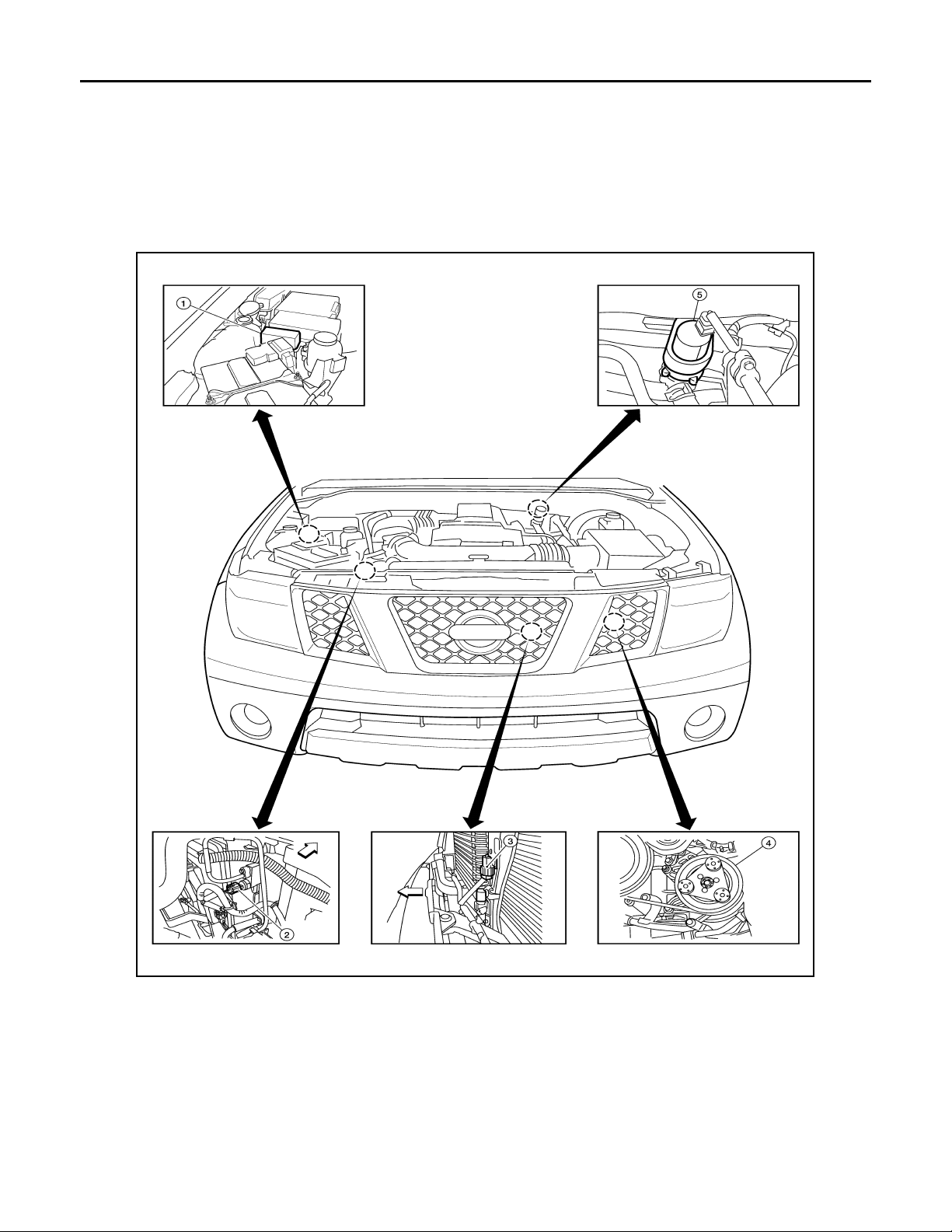
Component Part Location INFOID:0000000001366685
ENGINE COMPARTMENT
VQ40DE
1. Heater pump relay E144 2. Refrigerant pressure sensor E48
(View with battery removed)
⇐: Front
4. A/C Compressor F3 5. Heater pump E141
HAC-8
WJIA2270E
3. Ambient sensor E1 (View with grille
removed)

< FUNCTION DIAGNOSIS >
FUNCTION INFORMATION
[AUTOMATIC AIR CONDITIONER]
VK56DE
A
B
C
D
E
F
G
1. Refrigerant pressure sensor E48
(View with battery removed)
⇐: Front
4. Water valve F68
2. Ambient sensorE1 (View with grille
removed)
3. A/C Compressor F3
H
HAC
J
K
L
AWIIA0220ZZ
M
N
O
PASSENGER COMPARTMENT
P
HAC-9

< FUNCTION DIAGNOSIS >
FUNCTION INFORMATION
[AUTOMATIC AIR CONDITIONER]
1. A/C Auto amp. M49, M50 2. In-vehicle sensor M32 3. Intake sensor M146
4. Intake door motor M58 5. Variable blower control (front)
M122
7. Mode door motor (front) M142 8. Air mix door motor (passenger)
M143
⇐ :Front ⇐
6. Air mix door motor (driver) M147
9. Optical sensor M145
HAC-10
AWIIA0221ZZ

FUNCTION INFORMATION
< FUNCTION DIAGNOSIS >
REAR PASSENGER COMPARTMENT
[AUTOMATIC AIR CONDITIONER]
A
B
C
D
E
F
G
AWIIA0222ZZ
1. Rear air control (front) R2 2. Air mix door motor (rear) B155 3. Rear blower motor B501
4. Variable blower control (rear) B133 5. Rear air control (rear) M208
Symptom Table INFOID:0000000001366686
Symptom Reference Page
A/C system does not come on. Go to Trouble Diag nosis Procedure for A/C System. HAC-87
A/C system display is malfunctioning (with
NAVI).
A/C system display is malfunctioning (without
NAVI).
A/C system cannot be controlled. Go to Self-diagnosis Function. HAC-23
Air outlet does not change.
Mode door motor is malfunctioning.
Discharge air temperature does not change.
Air mix door motor is malfunctioning.
Go to Navigation System. AV-337
Go to Mid-level Audio System. AV-179
Go to Trouble Diagnosis Procedure for Mode Door Motor. HAC-27
Go to Trouble Diagnosis Procedure for Air Mix Door Motor. HAC-32
H
HAC
J
K
L
M
N
O
P
HAC-11

FUNCTION INFORMATION
< FUNCTION DIAGNOSIS >
Symptom Reference Page
Intake door does not change.
Intake door motor is malfunctioning.
Front blower motor operation is malfunction-
ing.
Rear blower motor operation is malfunction-
ing.
Rear discharge air temperature and/or air
outlet does not change.
Magnet clutch does not engage. Go to Trouble Diagnosis Procedure for Magnet Clutch. HAC-68
Insufficient cooling Go to Trouble Diagnosis Procedure for Insufficient Cooling. HAC-107
Insufficient heating Go to Trouble Diagnosis Procedure for Insufficient Heating. HAC-115
Noise Go to Trouble Diagnosis Procedure for Noise. HAC-117
Self-diagnosis cannot be performed. Go to Trouble Diagnosis Procedure for Self-diagnosis. HAC-87
Memory function does not operate. Go to Trouble Diagnosis Procedure for Memory Function. HAC-119
Go to Trouble Diagnosis Procedure for Intake Door Motor. HAC-43
Go to Trouble Diagnosis Procedure for Front Blower Motor. HAC-47
Go to Trouble Diagnosis Procedure for Rear Blower Motor. HAC-52
Go to Trouble Diagnosis Procedure for Rear Air Control circuit. HAC-61
[AUTOMATIC AIR CONDITIONER]
HAC-12

< FUNCTION DIAGNOSIS >
REFRIGERATION SYSTEM
[AUTOMATIC AIR CONDITIONER]
REFRIGERATION SYSTEM
Refrigerant Cycle INFOID:0000000001366687
Refer to HAC-13, "Refrigerant Cycle".
Refrigerant System Protection INFOID:0000000001366688
Refer to HAC-13, "Refrigerant System Protection".
A
B
C
D
E
F
G
H
HAC
J
K
L
M
N
O
P
HAC-13

AUTOMATIC AIR CONDITIONER SYSTEM
< FUNCTION DIAGNOSIS >
[AUTOMATIC AIR CONDITIONER]
AUTOMATIC AIR CONDITIONER SYSTEM
Control System Diagram INFOID:0000000001366689
CONTROL SYSTEM
The control system consists of input sensors, switches, the A/C auto amp. (microcomputer) and outputs.
The relationship of these components is shown in the figure below:
AWIIA0223GB
Control System Description INFOID:0000000001366690
CONTROL OPERATION
HAC-14

AUTOMATIC AIR CONDITIONER SYSTEM
< FUNCTION DIAGNOSIS >
[AUTOMATIC AIR CONDITIONER]
A/C Auto Amp.
A
B
C
D
E
AWIIA0081ZZ
DISPLAY SCREEN
Displays the operational status of the system.
AUTO SWITCH
• Pressing the AUTO switch will illuminate the LED and "Auto" will be visible on the display. The A/C indicator
will illuminate.
• The A/C compressor, intake door, air mix doors, outlet doors and blower speed are automatically controlled
so that the in-vehicle temperature will reach, and be maintained at the set temperature selected by the operator.
• When pressing AUTO switch, air inlet, air outlet, blower speed, and discharge air temperature are automatically controlled.
• A partial AUTO mode can be achieved by only changing the blower speed or by changing the mode position.
If both the blower speed and the mode positions are changed, the AUTO mode will be cancelled.
TEMPERATURE CONTROL DIAL (DRIVER)
Increases or decreases the set temperature.
TEMPERATURE CONTROL DIAL (PASSENGER)
Increases or decreases the set temperature.
RECIRCULATION ( ) SWITCH
• When REC switch is ON, REC switch indicator turns ON, and air inlet is set to REC.
• When REC switch is turned OFF, or when compressor is turned from ON to OFF, REC switch is automatically turned OFF. REC mode can be re-entered by pressing REC switch again.
• REC switch is not operated when DEF switch is turned ON, at the D/F position, or in floor position.
F
G
H
HAC
J
K
L
M
DEFROSTER ( ) SWITCH
Positions the air outlet doors to the defrost position. Also positions the intake doors to the outside air position,
and turns A/C compressor ON.
REAR WINDOW DEFOGGER SWITCH
When switch is ON, rear window and door mirrors are defogged.
OFF SWITCH
The A/C compressor and blower are OFF, the intake doors are set to the out side ai r position, and the ai r outl et
doors are set to the foot (75% foot and 25% defrost) position.
A/C SWITCH
The compressor is ON or OFF.
(Pressing the A/C switch when the AUTO switch is ON will turn off the A/C switch and compressor.)
MODE SWITCH
Controls the air discharge outlets.
HAC-15
N
O
P

AUTOMATIC AIR CONDITIONER SYSTEM
< FUNCTION DIAGNOSIS >
FRONT BLOWER CONTROL SWITCHES
Manually control the blower speed.
Rear Air Controls
1. Rear air control (front) 2. Rear air control (rear)
[AUTOMATIC AIR CONDITIONER]
AWIIA0224ZZ
TEMPERATURE CONTROL DIAL (TEMPERATURE AND MODE CONTROL)
The temperature increases or decreases the set temperature. The mode also changes from foot at full hot setting, to foot/vent at mid-range (warm) setting, and then to vent at full cold setting.
REAR BLOWER CONTROL DIAL (FRONT)
When the REAR CTRL switch is in the off (indicator off) the rear air control (front) controls the rear blower
motor speed regardless of the rear air control (rear) blower control dial (rear) position. The rear air control
(front) controls the blower motor speed.
REAR BLOWER CONTROL DIAL (REAR)
When the REAR CTRL switch is on (indicator on) the rear air control (rear) controls the rear blower motor
speed regardless of the rear air control (front) blower control dial (front) position. The rear air control (rear)
controls the blower motor speed.
MAGNET CLUTCH CONTROL
AWIIA0089GB
When A/C switch or DEF switch is pressed, A/C auto amp. inputs compressor ON signal to BCM.
BCM sends compressor ON signal to ECM and A/C auto amp., via CAN communication line.
HAC-16

AUTOMATIC AIR CONDITIONER SYSTEM
< FUNCTION DIAGNOSIS >
ECM judges whether compressor can be turned ON, based on each sensor status (refrigerant pressure sensor signal, throttle angle sensor, etc.). If it judges compressor can be turned ON, it sends compressor ON signal to IPDM E/R, via CAN communication line.
Upon receipt of compressor ON signal from ECM, IPDM E/R turns air conditioner relay ON to operate compressor.
[AUTOMATIC AIR CONDITIONER]
Discharge Air Flow (Front) INFOID:0000000001366691
LJIA0172E
Mode door position
Vent Foot Defroster
100% 0% —
Air outlet/distribution
A
B
C
D
E
F
G
H
60% 40% —
18% 64% 18%
14% 53% 33%
—13% 87%
HAC
J
K
L
M
N
O
HAC-17
P

AUTOMATIC AIR CONDITIONER SYSTEM
< FUNCTION DIAGNOSIS >
[AUTOMATIC AIR CONDITIONER]
Switches And Their Control Function (Front)
INFOID:0000000001366693
WJIA1680E
HAC-18
AWIIA0236GB

AUTOMATIC AIR CONDITIONER SYSTEM
< FUNCTION DIAGNOSIS >
[AUTOMATIC AIR CONDITIONER]
Switches And Their Control Function (Rear) INFOID:0000000001366694
A
B
C
D
E
F
G
AWIIA0239GB
H
HAC
J
K
L
M
N
O
HAC-19
P
AWIIA0240GB

CAN COMMUNICATION SYSTEM
< FUNCTION DIAGNOSIS >
[AUTOMATIC AIR CONDITIONER]
CAN COMMUNICATION SYSTEM
System Description INFOID:0000000001366695
Refer to LAN-4, "System Description".
HAC-20

< FUNCTION DIAGNOSIS >
DIAGNOSIS SYSTEM (HVAC)
[AUTOMATIC AIR CONDITIONER]
DIAGNOSIS SYSTEM (HVAC)
CONSULT-III Function (HVAC) INFOID:0000000001366696
CONSULT-III can display each diagnostic item using the diagnostic test modes shown following.
Diagnostic mode Description
SELF-DIAG RESULTS Displays A/C auto amp. self-diagnosis results.
DATA MONITOR Displays A/C auto amp. input/output data in real time.
CAN DIAG SUPPORT MNTR The result of transmit/receive diagnosis of CAN communication can be read.
ECU PART NUMBER A/C auto amp. part number can be read.
SELF-DIAGNOSIS
Display Item List
DTC Description
B2573 Battery voltage out of range CHG-4, "
B2578 In-vehicle sensor circuit out of range (low)
B2579 In-vehicle sensor circuit out of range (high)
B257B Ambient sensor circuit short
B257C Ambient sensor circuit open
B257F Optical sensor (Driver) circuit open or short
B2580 Optical sensor (Passenger) circuit open or short
B2581 Intake sensor circuit short
B2582 Intake sensor circuit open
U1000 CAN bus fau lt LAN-4, "
HAC-80, "
HAC-77, "
HAC-83, "
HAC-85, "
Work Flow"
In-Vehicle Sensor Diagnosis Procedure"
Ambient Sensor Diagnosis Procedure"
Optical Sensor Diagnosis Procedure".
Intake Sensor Diagnosis Procedure"
System Description"
Reference page
A
B
C
D
E
F
G
H
HAC
J
DATA MONITOR
Display Item List
Monitor item Value Contents
BATT VIA CAN "V" Displays battery voltage signal.
IGN VIA CAN "ON/OFF" Displays ignition switch signal.
DVR SUNLD SEN "w/m2" Displays optical sensor (driver) signal.
PAS SUNLD SEN "w/m2" Displays optical sensor (passenger) signal.
AMB TEMP SEN "°C/°F" Displays ambient sensor signal.
EVAP TEMP SEN "°C/°F" Displays intake sensor signal.
INCAR TMP SEN "°C/°F" Displays in-vehicle sensor signal.
RR TEMPSET FR "V" Displays air mix door (front) set point signal.
RR TEMPSET RR "V" Displays air mix door (rear) set point signal.
MODE FDBCK "V" Displays mode door motor feedback signal.
DVR MIX FDBCK "V" Displays air mix door motor (driver) feedback signal.
PAS MIX FDBCK "V" Displays air mix door motor (passenger) feedback signal.
RR FDBCK "V" Displays air mix door motor (rear) feedback signal.
K
L
M
N
O
P
HAC-21

DIAGNOSIS SYSTEM (BCM)
< FUNCTION DIAGNOSIS >
[AUTOMATIC AIR CONDITIONER]
DIAGNOSIS SYSTEM (BCM)
CONSULT-III Function (BCM) INFOID:0000000001366697
CONSULT-II can display each diagnostic item using the diagnostic test modes shown following.
BCM diagnostic
test item
Inspection by part
Diagnostic mode Description
Supports inspections and adjustments. Co mmands are transmit ted to the BCM for
WORK SUPPORT
DATA MONITOR Displays BCM input/output data in real time.
ACTIVE TEST Operation of electrical loads can be checked by sending drive signal to them.
SELF-DIAG RESULTS Displays BCM self-diagnosis results.
CAN DIAG SUPPORT MNTR The result of transmit/receive diagnosis of CAN communication can be read.
ECU PART NUMBER BCM part number can be read.
CONFIGURATION Performs BCM configuration read/write functions.
setting the status suit able for req uired operatio n, input/ou tput signals a re received
from the BCM and received data is displayed.
DATA MONITOR
Display Item List
Monitor item name “operation or
unit”
IGN ON SW “ON/OFF” Displays “IGN Position (ON)/OFF, ACC Position (OFF)” status as judged from ignition switch signal.
COMP ON SIG “ON/OFF” Displays “COMP (ON)/COMP (OFF)” status as judged from air conditioner switch signal.
FAN ON SIG “ON/OFF” Displays “FAN (ON)/FAN (OFF)” status as judged from blower motor switch signal.
Contents
HAC-22

< FUNCTION DIAGNOSIS >
Z
SELF-DIAGNOSIS FUNCTION
[AUTOMATIC AIR CONDITIONER]
SELF-DIAGNOSIS FUNCTION
A/C Auto Amp. Self-Diagnosis INFOID:0000000001366698
A/C SYSTEM SELF-DIAGNOSIS FUNCTION
The self-diagnosis function is built into the A/C auto amp. to quickly locate the cause of malfunctions.
DESCRIPTION
The self-diagnostic system diagnoses sensors, CAN system, and battery voltage on A/C auto amp. Refer to
applicable sections (items) for details. Fault codes (if any are present) will be displayed in the ambient temperature display area. Refer to HAC-24, "
SELF-DIAGNOSTIC MODE
NOTE:
Radio must be OFF.
1. Turn the ignition switch ON.
2. On the A/C and AV switch assembly, press the "SETTING" button and twist the volume knob clockwise and counterclockwise
until the Self-Diagnosis screen shows on the display.
3. Scroll down to "Confirmation/Adjustment" and press the
"ENTER" button.
4. Scroll down to "Climate Control" and press the "ENTER" button.
5. The fan bars will flash on the display during the self-test, and
then the fault codes will display in the ambient temperature area.
They will continue scrolling until diagnostic mode is exited.
6. Exit by pressing the "BACK" button on A/C and AV switch
assembly until display returns to its normal operation screen.
HVAC system will be OFF or by turning the ignition switch OFF.
A/C System Self-Diagnosis Code Chart".
AWNIA0098Z
A
B
C
D
E
F
G
H
HAC
The self-diagnostic system diagnoses sensors, CAN system, and battery voltage on A/C auto amp. Refer to
applicable sections (items) for details. Fault codes (if any are present) will be displayed in the ambient temperature display area. Refer to HAC-24, "
A/C System Self-Diagnosis Code Chart".
AWIIA0081ZZ
A/C and AV Switch Assembly Self-Diagnosis INFOID:0000000001366699
J
K
L
M
N
O
P
A/C and AV switch assembly self-diagnosis function
The ON/OFF operation (continuity) of each switch in the A/C and AV switch assembly can be checked.
Self-diagnosis mode
HAC-23

SELF-DIAGNOSIS FUNCTION
< FUNCTION DIAGNOSIS >
• Press the “BACK” switch and the “UP” switch within 10 seconds
after turning the ignition switch from OFF to ACC and hold them for
3 seconds or more. Then the buzzer sounds, all indicators of the
preset switch illuminate, and the self-diagnosis mode starts.
• The continuity of each switch and control dials (A/C and AV switch
assembly only) at the ON position can be checked by pressing
each switch and turning each control dial. The buzzer sounds and
LED's will illuminate if the switch is normal.
Finishing self-diagnosis mode
Self-diagnosis mode is canceled when turning the ignition switch OFF.
[AUTOMATIC AIR CONDITIONER]
AWIIA0171GB
A/C System Self-Diagnosis Code Chart INFOID:0000000001366700
SELF-DIAGNOSTIC CODE CHART
Code No. Reference page
02 EE changed by calibration VTL-8, "
03 Battery voltage out of range CHG-10, "Inspection Procedure"
12 Passenger air mix door open/short/out of limits
22 Driver air mix door open/short HAC-33, "Air Mix Door Motor (Driver) Diagnosis Procedure"
30 In-vehicle sensor circuit out of range (low)
31 In-vehicle sensor c ircuit out of range (high)
38 Air mix door motor (rear) circuit failure HAC-61, "
40 Ambient sensor circuit short
41 Ambient sensor circuit open
44 Intake door motor open
46 Intake door motor short
50 Optical sensor (Driver) circuit open or short
52 Optical sensor (Passenger) circuit open or short
56 Intake sensor circuit short
57 Intake sensor circuit open
80 CAN bus fault
81 BCM message missing
82 Intake door motor circuit malfunction HAC-43, "Intake Door Motor Diagnosis Procedure"
90 Stuck button VTL-8, "Removal and Installation "
92 Mode door motor circuit malfunction
HAC-37, "
dure"
HAC-80, "
HAC-77, "
HAC-43, "
HAC-83, "
HAC-157, "
LAN-14, "
HAC-26, "
Check"
Removal and Installation"
Air Mix Door Motor (Passenger) Diagnosis Proce-
In-Vehicle Sensor Diagnosis Procedure"
Rear Air Control Component Function Check "
Ambient Sensor Diagnosis Procedure"
Intake Door Motor Diagnosis Procedure"
Optical Sensor Diagnosis Procedure"
Intake Sensor Diagnosis Procedure"
Trouble Diagnosis Flow Chart"
Mode Door Motor (Front) Component Function
HAC-24

< COMPONENT DIAGNOSIS >
MODE DOOR MOTOR
[AUTOMATIC AIR CONDITIONER]
COMPONENT DIAGNOSIS
MODE DOOR MOTOR
System Description INFOID:0000000001366701
SYSTEM DESCRIPTION
Component Parts
Mode door control system components are:
• A/C auto amp.
• A/C and AV switch assembly
• Mode door motor (front)
• PBR (built into mode door motor)
• In-vehicle sensor
• Ambient sensor
• Optical sensor
• Intake sensor
System Operation
The mode door position (vent, B/L, foot, D/F, and defrost) is set by the A/C auto amp. by means of the mode
door motor (front). When a mode door position is selected on the A/C auto amp., voltage is applied to one circuit of the mode door motor (front) while ground is applied to the other circuit, causing the mode door motor
(front) to rotate. The direction of rotation is determined by which circuit has voltage applied to it, and which one
has ground applied to it. The A/C auto amp. monitors the mode door position by measuring the voltage signal
on the PBR circuit.
In AUTO mode the mode door position is set by the A/C auto amp. which determines the proper position
based on inputs from the in-vehicle sensor, ambient sensor, optical sensor , intake sensor, and the temperature
selected by the driver or passenger.
A
B
C
D
E
F
G
H
HAC
Mode Door Control Specification
COMPONENT DESCRIPTION
Mode Door Motor (Front)
J
K
L
M
N
AWIIA0092GB
O
P
HAC-25
AWIIA0093GB

MODE DOOR MOTOR
< COMPONENT DIAGNOSIS >
The mode door motor (front) is attached to the heater & cooling unit
assembly. It rotates so that air is discharged from the outlet as indicated by the A/C auto amp. Motor rotation is conveyed to a link
which activates the mode door.
[AUTOMATIC AIR CONDITIONER]
WJIA1084E
Mode Door Motor (Front) Component Function Check INFOID:0000000001366702
INSPECTION FLOW
1.CONFIRM SYMPTOM BY PERFORMING OPERATIONAL CHECK - DISCHARGE AIR
1. Press mode switch four times and then press the (DEF) switch. Each position indicator should change
shape (on display).
2. Confirm that discharge air comes out according to the air distribution table. Refer to HAC-131, "
Air Flow".
NOTE:
Confirm that the compressor clutch is engaged (visual inspection) and intake door position is at FRESH
when FOOT ( ), DEF ( ) or D/F ( ) is selected.
Can a symptom be duplicated?
YES >> GO TO 3.
NO >> GO TO 2.
Discharge
2.PERFORM COMPLETE OPERATIONAL CHECK
Perform a complete operational check and check for any symptoms. Refer to HAC-123, "
Can a symptom be duplicated?
YES >> Refer to HAC-122, "How to Perform Trouble Diagnosis For Quick And Accurate Repair".
NO >> System OK.
Operational Check".
3.CHECK FOR SERVICE BULLETINS
Check for any service bulletins.
>> GO TO 4.
4.CHECK MODE DOOR OPERATION
Check and verify mode door mechanism for smooth operation in each mode.
Is the inspection result normal?
YES >> GO TO 5.
NO >> Repair as necessary.
5.PERFORM A/C AUTO AMP. SELF-DIAGNOSIS
Perform self-diagnosis to check for any codes. Refer to HAC-23, "
Are any self-diagnosis codes present?
YES >> Refer to HAC-24, "A/C System Self-Diagnosis Code Chart".
NO >> GO TO 6.
A/C Auto Amp. Self-Diagnosis".
6.PERFORM A/C AND AV SWITCH ASSEMBLY SELF-DIAGNOSIS
Perform self-diagnosis to check the A/C and AV switch assembly. Refer to HAC-23, "
Assembly Self-Diagnosis".
Is the inspection result normal?
YES >> Replace A/C and AV switch assembly. Refer to VTL-8, "Removal and Installation".
NO >> GO TO 6.
A/C and AV Switch
HAC-26
< COMPONENT DIAGNOSIS >
MODE DOOR MOTOR
[AUTOMATIC AIR CONDITIONER]
7.CHECK THE MODE DOOR MOTOR (FRONT) PBR CIRCUIT
Perform diagnostic procedure for the mode door motor (front). Refer to HAC-135, "
Component Function Check".
Is the inspection result normal?
YES >> GO TO 8.
NO >> Repair PBR circuit or replace motor. Refer to HAC-136, "
cedure".
Mode Door Motor (Front) Diagnosis Pro-
Mode Door Motor (Front)
8.RECHECK FOR CODES
Perform A/C auto amp. self-diagnosis. Refer to HAC-23, "
Are any self-diagnostic codes present?
YES >> Refer to HAC-24, "A/C System Self-Diagnosis Code Chart".
NO >> GO TO 9.
A/C Auto Amp. Self-Diagnosis".
9.RECHECK FOR SYMPTOMS
Perform a complete operational check and check for any symptoms. Refer to HAC-123, "
Does another symptom exist?
YES >> Repair as necessary.
NO >> Replace A/C auto amp. Refer to VTL-8, "
Removal and Installation".
Mode Door Motor (Front) Diagnosis Procedure INFOID:0000000001366703
SYMPTOM:
• Air outlet does not change.
• Mode door motor does not operate normally.
Operational Check".
A
B
C
D
E
F
G
H
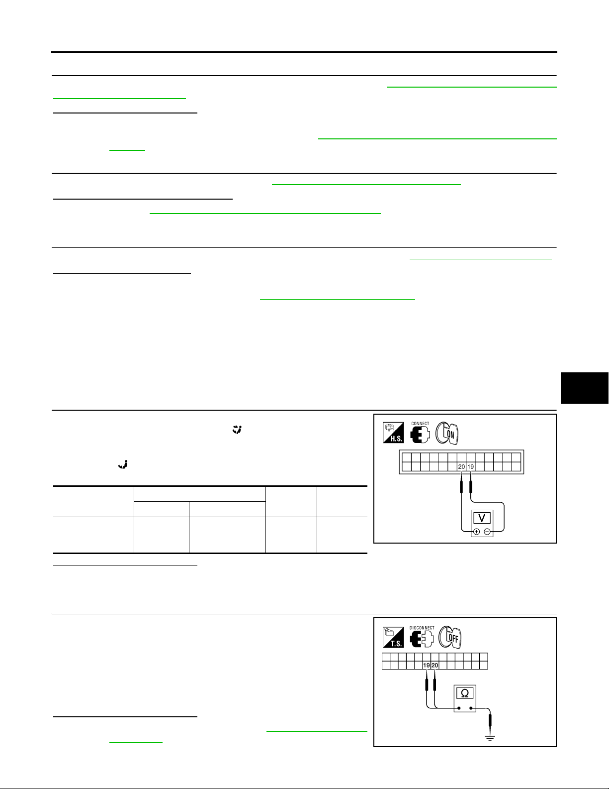
1.CHECK A/C AUTO AMP. FOR POWER AND GROUND
1. Turn ignition switch ON.
2. Press the mode switch to the B/L ( ) mode.
3. Check voltage between A/C auto amp. harness connector M49
terminal 19 and terminal 20 while pressing the mode switch to
the floor ( ) mode.
Connector
A/C auto amp.:
M49
Is the inspection result normal?
YES >> GO TO 4.
NO >> GO TO 3.
Terminals
(+) (-)
20 19
Condition
Press
mode
switch
Voltage
(Approx.)
Battery
voltage
2.CHECK MODE DOOR MOTOR CIRCUITS FOR SHORT TO GROUND
1. Turn ignition switch OFF.
2. Disconnect the A/C auto amp. harness connector.
3. Check continuity between A/C auto amp. harness connector
M49 terminal 19, 20 and ground.
19 - Ground : Continuity should not exist.
20 - Ground : Continuity should not exist.
HAC
J
K
L
AWIIA0095ZZ
M
N
O
P
Is the inspection result normal?
YES >> Replace A/C auto amp. Refer to VTL-8, "Removal and
Installation".
NO >> Repair or replace harness as necessary.
HAC-27
AWIIA0096ZZ
MODE DOOR MOTOR
< COMPONENT DIAGNOSIS >
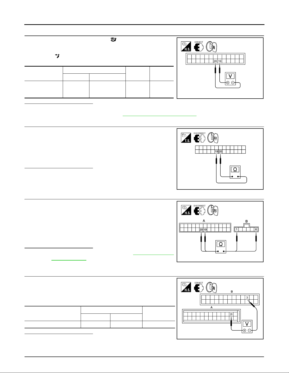
3.CHECK A/C AUTO AMP. FOR GROUND AND POWER
1. Press the mode switch to the D/F ( ) mode.
2. Check voltage between A/C auto amp. harness connector M49
terminal 19 and terminal 20 while pressing the mode switch to
the vent ( ) mode.
[AUTOMATIC AIR CONDITIONER]
Connector
A/C auto amp.:
M49
Terminals
(+) (-)
19 20
Condition
Press
mode
switch
Voltage
(Approx.)
Battery
voltage
Is the inspection result normal?
YES >> GO TO 5.
NO >> Replace A/C auto amp. Refer to VTL-8, "
Removal and Installation".
4.CHECK MODE DOOR MOTOR AND CIRCUITS FOR OPEN
1. Turn ignition switch OFF.
2. Disconnect the A/C auto amp. harness connector.
3. Check continuity between A/C auto amp. harness connector
M49 terminal 19 and terminal 20.
Continuity should exist.
Is the inspection result normal?
YES >> GO TO 7.
NO >> GO TO 6.
5.CHECK MODE DOOR MOTOR CIRCUITS FOR OPEN
1. Disconnect the mode door motor harness connector.
2. Check continuity between A/C auto amp. harness connector
M49 (A) terminal 19, 20 and the mode door motor harness connector M142 (B) terminal 1, 6.
AWIIA0097ZZ
AWIIA0098ZZ
6 - 19 : Continuity should exist.
1 - 20 : Continuity should exist.
Is the inspection result normal?
YES >> Replace mode door motor. Refer to VTL-28, "Removal
and Installation".
NO >> Repair or replace harness as necessary.
6.CHECK A/C AUTO AMP. FOR PBR POWER AND GROUND
1. Reconnect A/C auto amp. harness connector.
2. Turn ignition switch ON.
3. Check voltage between A/C auto amp. harness connector M50
(A) terminal 28 and M49 (B) terminal 3.
Connector
A/C auto amp.: M49, M50 28 3 5V
Terminals
(+) (-)
Voltage (Ap-
prox.)
Is the inspection result normal?
YES >> GO TO 9.
NO >> GO TO 8.
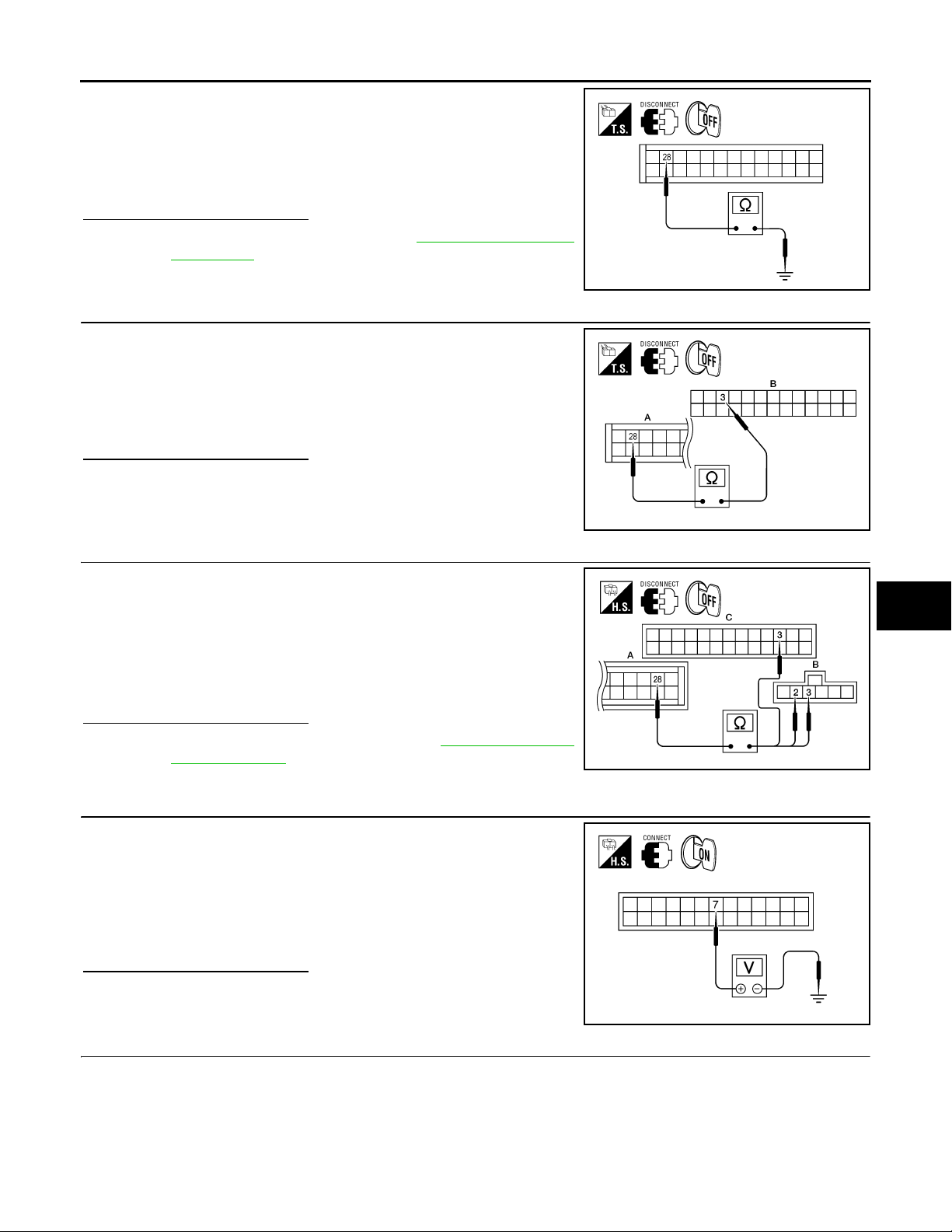
7.CHECK PBR REFERENCE VOLTAGE CIRCUIT FOR SHORT TO GROUND
HAC-28
AWIIA0225ZZ
AWIIA0099ZZ
MODE DOOR MOTOR
< COMPONENT DIAGNOSIS >
1. Turn ignition switch OFF.
2. Disconnect the A/C auto amp. harness connector.
3. Check continuity between A/C auto amp. harness connector
M50 terminal 28 and ground.
[AUTOMATIC AIR CONDITIONER]
A
Continuity should not exist.
Is the inspection result normal?
YES >> Replace A/C auto amp. Refer to VTL-8, "Removal and
Installation".
NO >> Repair or replace harness as necessary.
8.CHECK PBR REFERENCE VOLTAGE AND GROUND CIRCUITS
1. Turn ignition switch OFF.
2. Disconnect the A/C auto amp. harness connector.
3. Check continuity between A/C auto amp. harness connector
M50 (A) terminal 28 and M49 (B) terminal 3.
Continuity should exist.
Is the inspection result normal?
YES >> GO TO 11.
NO >> GO TO 10
9.CHECK PBR REFERENCE VOLTAGE CIRCUIT FOR OPEN
1. Disconnect the mode door motor harness connector.
2. Check continuity between mode door motor harness connector
M142 (B) terminal 3, 1 and A/C auto amp. harness connector
M49 (C) terminal 3, M50 (A) terminal 28.
B
C
AWIIA0100ZZ
D
E
F
G
AWIIA0101ZZ
H
HAC
28 - 3 : Continuity should exist.
3 - 2 : Continuity should exist.
Is the inspection result normal?
YES >> Replace mode door motor. Refer to VTL-28, "Removal
and Installation".
NO >> Repair or replace harness as necessary.
10.CHECK PBR FEEDBACK VOLTAGE
1. Reconnect the A/C auto amp. harness connector.
2. Turn ignition switch ON.
3. Check voltage between A/C auto amp. harness connector M49
terminal 7 and ground while cycling mode switch through all
modes.
Voltage : Approx. 1V - 4.5V
Is the inspection result normal?
YES >> GO TO 13.
NO >> GO TO 12.
11.CHECK PBR FEEDBACK SIGNAL CIRCUIT FOR SHORT TO GROUND
J
K
AWIIA0226ZZ
L
M
N
O
AWIIA0103ZZ
P
HAC-29

MODE DOOR MOTOR
< COMPONENT DIAGNOSIS >
1. Turn ignition switch OFF.
2. Disconnect A/C auto amp. harness connector.
3. Check continuity between A/C auto amp. harness connector
M49 terminal 7 and ground.
Continuity should not exist.
Is the inspection result normal?
YES >> Replace A/C auto amp. Refer to VTL-8, "Removal and
Installation".
NO >> Repair or replace harness as necessary.
12.CHECK PBR FEEDBACK CIRCUIT FOR OPEN
1. Turn ignition switch OFF.
2. Disconnect the mode door motor harness connector and A/C
auto amp. harness connector.
3. Check continuity between mode door motor harness connector
M142 terminal 4 and A/C auto amp. harness connector M49 terminal 7.
Continuity should exist.
Is the inspection result normal?
YES >> Replace mode door motor. Refer to VTL-28, "Removal
and Installation".
NO >> Repair or replace harness as necessary.
[AUTOMATIC AIR CONDITIONER]
AWIIA0104ZZ
AWIIA0227ZZ
HAC-30
 Loading...