


 Loading...
ACCELERATOR CONTROL, FUEL & EXHAUST SYSTEMS
SECTION FE
CONTENTS
QG/SR |
|
PREPARATION ............................................................... |
2 |
Special Service Tools .................................................. |
2 |
Commercial Service Tools ........................................... |
2 |
ACCELERATOR CONTROL SYSTEM ........................... |
3 |
Removal and Installation ............................................. |
3 |
Adjusting Accelerator Wire .......................................... |
3 |
MODELS WITH THROTTLE OPENER......................... |
3 |
MODELS WITHOUT THROTTLE OPENER .................. |
4 |
FUEL SYSTEM ................................................................ |
5 |
Checking Fuel Lines .................................................... |
5 |
Removal and Installation ............................................. |
5 |
Fuel Tank ..................................................................... |
6 |
REMOVAL................................................................. |
6 |
INSTALLATION.......................................................... |
8 |
Fuel Pump, Fuel Level Sensor Unit and Fuel |
|
Filter ............................................................................. |
9 |
REMOVAL................................................................. |
9 |
INSTALLATION........................................................ |
10 |
EXHAUST SYSTEM ...................................................... |
11 |
Checking Exhaust System......................................... |
11 |
Removal and Installation ........................................... |
11 |
YD |
|
PREPARATION ............................................................. |
13 |
Special Service Tool .................................................. |
13 |
Commercial Service Tool........................................... |
13 |
ACCELERATOR CONTROL SYSTEM ......................... |
14 |
Removal and Installation ........................................... |
14 |
Inspection................................................................... |
14 |
FUEL SYSTEM .............................................................. |
15 |
Checking Fuel Lines .................................................. |
15 |
Water Draining from Fuel Filter ................................. |
15 |
DRAINING WATER .................................................. |
15 |
FUEL FILTER CHECK.............................................. |
15 |
Changing Fuel Filter .................................................. |
15 |
REMOVAL............................................................... |
15 |
INSTALLATION........................................................ |
16 |
Bleeding Fuel Filter.................................................... |
16 |
Checking Priming Pump ............................................ |
16 |
Checking Water in Fuel Filter Sensor (where |
|
fitted) .......................................................................... |
17 |
Removal and Installation ........................................... |
17 |
Fuel Tank ................................................................... |
18 |
REMOVAL............................................................... |
19 |
INSTALLATION........................................................ |
20 |
Fuel Level Sensor Unit .............................................. |
21 |
REMOVAL............................................................... |
21 |
INSTALLATION........................................................ |
22 |
EXHAUST SYSTEM ...................................................... |
23 |
Checking Exhaust System......................................... |
23 |
Removal and Installation ........................................... |
23 |
|
PREPARATION |
|
QG/SR |
Special Service Tools |
|
|
|
|
|
|
|
|
Special Service Tools |
|
NLFE0029 |
|
|
|
|
|
|
|
|
Tool number |
Description |
|
|
Tool name |
|
|
|
|
|
|
|
|
|
|
|
KV10114400 |
|
Loosening or tightening front and rear |
|
Heated oxygen sensor |
|
heated oxygen sensors |
|
wrench |
|
a: 22 mm (0.87 in) |
|
|
NT636 |
|
|
|
|
|
|
KV999G0010 |
|
Removing and installing fuel tank lock |
|
Fuel tank lock ring |
|
ring |
|
socket |
|
|
|
|
NT057 |
|
|
|
|
|
|
|
Commercial Service Tools |
|
|
NLFE0030 |
|
Tool number |
Description |
|
Tool name |
||
|
||
|
|
|
Oxygen sensor thread |
Reconditioning the exhaust system threads |
|
cleaner |
before installing a new oxygen sensor (Use |
|
|
with anti-seize lubricant shown below.) |
|
|
a: 18 mm dia. with pitch 1.5 mm for zir- |
|
|
conia oxygen sensor |
|
|
b: 12 mm dia. with pitch 1.25 mm for |
|
|
titania oxygen sensor |
|
|
AEM488 |
|
|
|
|
Anti-seize lubricant |
Lubricating oxygen sensor thread cleaning |
|
(Permatex 133AR or |
tool when reconditioning exhaust system |
|
equivalent meeting MIL |
threads |
|
specification MIL-A- |
|
|
907) |
|
AEM489
FE-2

ACCELERATOR CONTROL SYSTEM
QG/SR
Removal and Installation
Removal and Installation
NLFE0002
CAUTION:
+When removing accelerator wire, make a mark to indicate lock nut’s initial position.
+Check that throttle valve opens fully when accelerator pedal is fully depressed. Also check that it returns to idle position when pedal is released.
+Check accelerator control parts for improper contact with any adjacent parts.
+When connecting accelerator wire, be careful not to twist or scratch wire.
YFE002
Adjusting Accelerator Wire
NLFE0003
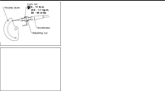
MODELS WITH THROTTLE OPENER
1. |
NLFE0003S01 |
Remove the vacuum hose connected to the throttle opener. |
|
2. |
Connect suitable vacuum hose to vacuum pump as shown left. |
3. |
Apply vacuum [more than −40. 0 kPa (−40. 0 bar, −30 0 mmHg, |
|
− 11.81 inHg)] until the throttle drum becomes free from the rod |
|
of the throttle opener. |
|
Make sure that there is clearance between the throttle |
|
drum and rod. |
|
If NG, refer to EC-99 (QG), EC-623 (SR) “Basic Inspection”. |
SEF793WB |
If OK, go to following step. |
FE-3
ACCELERATOR CONTROL SYSTEM |
QG/SR |
Adjusting Accelerator Wire (Cont’d)
4.Loosen lock nut.
5.Tighten accelerator adjusting nut until throttle drum starts to move.
6.From that position, turn back adjusting nut 1.5 to 2 turns, and secure lock nut.
7.Release vacuum from the throttle opener.
8.Remove vacuum pump and vacuum hose from the throttle opener.
9.Reinstall the original vacuum hose to the throttle opener securely.
NFE020
MODELS WITHOUT THROTTLE OPENER
NLFE0003S02
1.Loosen lock nut, and tighten adjusting nut until throttle drum starts to move.
2.From that position turn back adjusting nut 1.5 to 2 turns, and secure lock nut.
NFE020
FE-4
FUEL SYSTEM
QG/SR
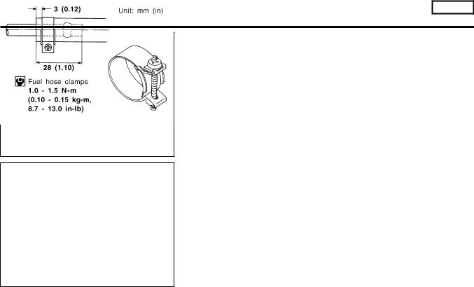
Checking Fuel Lines
Checking Fuel Lines
NLFE0009
Inspect fuel lines and tank for improper attachment, leaks, cracks, damage, loose connections, chafing or deterioration.
If necessary, repair or replace faulty parts.
SMA803A
CAUTION:
Tighten high-pressure rubber hose clamp so that clamp end is 3 mm (0.12 in) from hose end.
Tightening torque specifications are the same for all rubber hose clamps.
Ensure that screw does not contact adjacent parts.
MMA104A
Removal and Installation
NLFE0004
WARNING:
When replacing fuel line parts, be sure to observe the following.
+Put a “CAUTION: FLAMMABLE” sign in workshop.
+Be sure to furnish workshop with a CO2 fire extinguisher.
+Do not smoke while servicing fuel system. Keep open flames and sparks away from work area.
CAUTION:
+Before removing fuel line parts, carry out the following procedures:
a)Put drained fuel in an explosion-proof container and put the lid on securely.
b)Release fuel pressure from fuel line. Refer to EC-43 (QG), EC-577 (SR) “Fuel Pressure Release”.
c)Disconnect battery ground cable.
+Always replace O-ring and clamps with new ones.
+Do not kink or twist tubes when they are being installed.
+Do not tighten hose clamps excessively to avoid damaging hoses.
+After installing tubes, run engine and check for fuel leaks at connections.
FE-5

FUEL SYSTEM |
QG/SR |
Fuel Tank
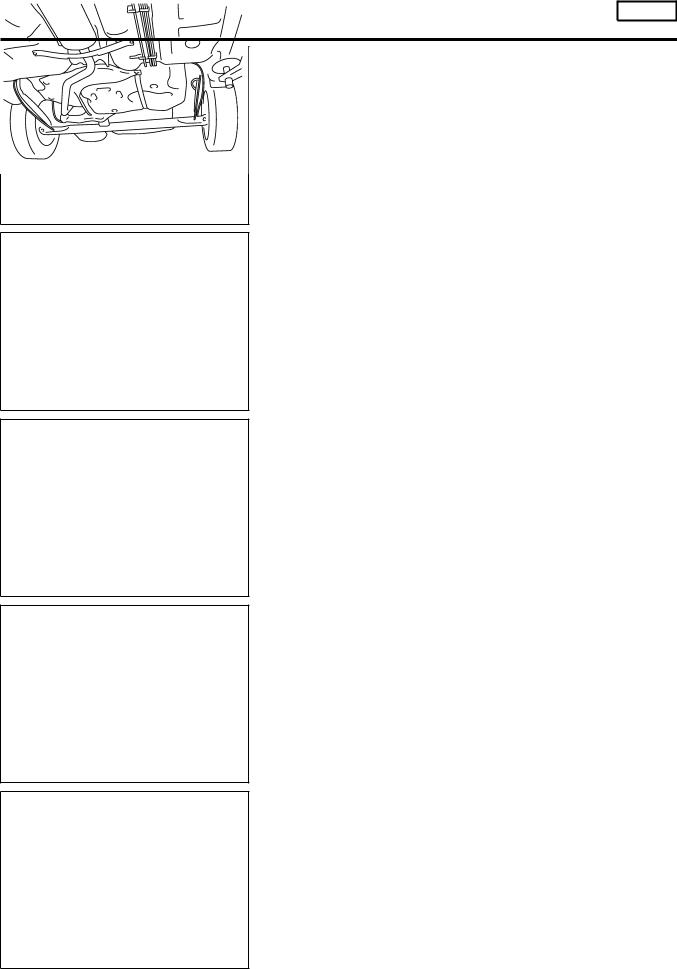
Fuel Tank
NLFE0006
YFE005
REMOVAL
NLFE0006S01
1.Disconnect battery ground cable.
2.Open fuel filler lid and filler cap.
3.Drain fuel from fuel tank.
4.Remove rear seat cushion. Refer to BT-49, “Removal and Installation”.
5.Remove inspection hole cover under the rear seat.
JFE613A
FE-6
FUEL SYSTEM
QG/SR
Fuel Tank (Cont’d)
SFE639A
SFE640A
SFE562A
6.Disconnect electrical connector.
7.Disconnect the quick connector as follows.
a.Put mating marks on tubes and connectors for correct installation.
b.Hold the connector while pushing in tabs, and pull out the tube.
CAUTION:
+The tube can be removed when the tabs are completely depressed. Do not twist it more than necessary.
+Do not use any tools to remove the quick connector.
+Keep the resin tube away from heat. Be especially careful when welding near the tube.
+Prevent acid liquid such as battery electrolyte etc. from getting on the resin tube.
+Do not bend or twist the tube during installation and
removal.
8.From rear left area of fuel tank, remove filler hose, vent hose, and EVAP hose.
CAUTION:
To prevent fuel from flowing out, install a blind cap immediately after the fuel hose is disconnected.
SFE650A
9.Remove exhaust center tube.
SFE642A
FE-7

FUEL SYSTEM |
QG/SR |
Fuel Tank (Cont’d)
10. Remove heat insulators from fuel tank side.
SFE643A
SFE644A
NFE069
11.Set a suitable transmission jack under fuel tank.
12.Remove fuel tank mounting band bolts while supporting fuel tank.
13.Remove fuel tank.
INSTALLATION
NLFE0006S02
To install, reverse the removal procedure. Connect the quick connector as follows:
+Align mating marks on tubes and connectors for correct installation.
+Insert tube into the center of the connector until you hear a click.
After connecting quick connector, make sure the connection is firmly made using the following method.
+Pull on the fuel tube and connector to make sure they are firmly connected.
+Start the engine, increase engine speed and verify that there are no leaks.
NFE070
FE-8
Loading...