


 Loading...
STEERING SYSTEM
SECTION ST
CONTENTS
PRECAUTIONS ............................................................... |
2 |
Supplemental Restraint System (SRS) ²AIR |
|
BAG² and ²SEAT BELT PRE-TENSIONER²............... |
2 |
Precautions for Steering System................................. |
2 |
PREPARATION ............................................................... |
3 |
Special Service Tools .................................................. |
3 |
Commercial Service Tool............................................. |
4 |
NOISE, VIBRATION AND HARSHNESS (NVH) |
|
TROUBLESHOOTING ..................................................... |
5 |
NVH Troubleshooting Chart......................................... |
5 |
ON-VEHICLE SERVICE .................................................. |
6 |
Checking Steering Wheel Play.................................... |
6 |
Checking Neutral Position on Steering Wheel ............ |
6 |
PRE-CHECKING........................................................ |
6 |
CHECKING ............................................................... |
6 |
Front Wheel Turning Angle.......................................... |
6 |
Checking Gear Housing Movement ............................ |
6 |
Checking and Adjusting Drive Belts ............................ |
7 |
Checking Steering Gear and Linkage ......................... |
7 |
STEERING GEAR...................................................... |
7 |
STEERING LINKAGE ................................................. |
7 |
Checking Fluid Level ................................................... |
7 |
Checking Fluid Leakage .............................................. |
7 |
Bleeding Hydraulic System.......................................... |
8 |
Checking Steering Wheel Turning Force .................... |
8 |
Checking Hydraulic System......................................... |
9 |
STEERING WHEEL AND STEERING COLUMN ......... |
11 |
Components............................................................... |
11 |
Removal and Installation ........................................... |
11 |
STEERING WHEEL ................................................. |
11 |
STEERING COLUMN ............................................... |
12 |
Disassembly and Assembly....................................... |
14 |
Inspection................................................................... |
15 |
TILT MECHANISM ................................................... |
15 |
POWER STEERING GEAR AND LINKAGE ................ |
16 |
Components............................................................... |
16 |
Removal and Installation ........................................... |
17 |
Disassembly............................................................... |
18 |
Inspection................................................................... |
19 |
BOOT ..................................................................... |
19 |
RACK ..................................................................... |
19 |
GEAR SUB-ASSEMBLY ........................................... |
19 |
GEAR HOUSING CYLINDER.................................... |
19 |
TIE-ROD OUTER AND INNER SOCKETS.................. |
20 |
Assembly ................................................................... |
20 |
Adjustment ................................................................. |
23 |
POWER STEERING OIL PUMP (QG ENGINE) ........... |
25 |
Components............................................................... |
25 |
Pre-disassembly Inspection....................................... |
25 |
Disassembly............................................................... |
26 |
Inspection................................................................... |
27 |
Assembly ................................................................... |
27 |
POWER STEERING OIL PUMP (YD ENGINE) ............ |
29 |
Components............................................................... |
29 |
Pre-disassembly Inspection....................................... |
29 |
Removal and Installation ........................................... |
30 |
Disassembly............................................................... |
30 |
Inspection................................................................... |
31 |
Assembly ................................................................... |
32 |
SERVICE DATA AND SPECIFICATIONS (SDS) ......... |
33 |
General Specifications............................................... |
33 |
Steering Wheel .......................................................... |
33 |
Steering Column ........................................................ |
33 |
Steering Gear and Linkage ....................................... |
34 |
Power Steering .......................................................... |
35 |

PRECAUTIONS
Supplemental Restraint System (SRS) ªAIR BAGº and ªSEAT BELT PRE-TENSIONERº
Supplemental Restraint System (SRS) ªAIR
BAGº and ªSEAT BELT PRE-TENSIONERº
NJST0044
The Supplemental Restraint System such as ªAIR BAGº and ªSEAT BELT PRE-TENSIONERº used along with a seat belt, helps to reduce the risk or severity of injury to the driver and front passenger for certain types of collision. The SRS system composition which is available to NISSAN MODEL N16 is as follows (The composition varies according to the destination and optional equipment.):
+For a frontal collision
The Supplemental Restraint System consists of driver air bag module (located in the center of the steering wheel), front passenger air bag module (located on the instrument panel on passenger side), front seat belt pre-tensioners, a diagnosis sensor unit, warning lamp, wiring harness and spiral cable.
+For a side collision
The Supplemental Restraint System consists of front side air bag module (located in the outer side of front seat), side air bag (satellite) sensor, diagnosis sensor unit (one of components of air bags for a frontal collision), wiring harness, warning lamp (one of components of air bags for a frontal collision).
Information necessary to service the system safely is included in the RS section of this Service Manual.
WARNING:
+To avoid rendering the SRS inoperative, which could increase the risk of personal injury or death in the event of a collision which would result in air bag inflation, all maintenance should be performed by an authorized NISSAN dealer.
+Improper maintenance, including incorrect removal and installation of the SRS, can lead to personal injury caused by unintentional activation of the system. For removal of Spiral Cable and Air Bag Module, see the RS section.
+Do not use electrical test equipment on any circuit related to the SRS unless instructed to in this Service Manual. SRS wiring harnesses (except ªSEAT BELT PRE-TENSIONERº connector) can be identified by yellow harness connector.
Precautions for Steering System
NJST0003
+Before disassembly, thoroughly clean the outside of the unit.
+Disassembly should be done in a clean work area. It is important to prevent the internal parts from becoming contaminated by dirt or other foreign matter.
+Place disassembled parts in order, on a parts rack, for easier and proper assembly.
+Use nylon cloths or paper towels to clean the parts; common shop rags can leave lint that might interfere with their operation.
+Before inspection or reassembly, carefully clean all parts with a general purpose, non-flammable solvent.
+Before assembly, apply a coat of recommended power steering fluid* to hydraulic parts. Vaseline may be applied to O-rings and seals. Do not use any grease.
+Replace all gaskets, seals and O-rings. Avoid damaging O-rings, seals and gaskets during instal-
lation. Perform functional tests whenever designated.
*: DEXRONTMIII or equivalent. Refer to MA-16, ªFluids and Lubricantsº.
ST-2
PREPARATION
Special Service Tools
|
Special Service Tools |
|
|
NJST0004 |
|
Tool number |
Description |
|
Tool name |
||
|
||
|
|
|
KV48100700 |
Measuring pinion rotating torque |
|
Torque adapter |
|
|
|
NT169 |
|
|
|
|
KV48102500 |
Measuring oil pressure |
|
Pressure gauge adapter |
|
|
|
NT542 |
|
|
|
|
ST27180001 |
Removing steering wheel |
|
Steering wheel puller |
|
|
|
NT544 |
|
HT72520000 |
Removing ball joint |
|
Ball joint remover |
a: 33 mm (1.30 in) |
|
|
b: 50 mm (1.97 in) |
|
|
r: R11.5 mm (0.453 in) |
|
|
NT546 |
|
|
|
|
KV48103500 |
Measuring oil pressure |
|
Pressure gauge |
|
|
|
NT547 |
|
|
|
|
KV48104400 |
Reforming teflon ring |
|
Rack seal ring reformer |
a: 50 mm (1.97 in) dia. |
|
|
b: 36 mm (1.42 in) dia. |
|
|
c: 100 mm (3.94 in) |
|
|
NT550 |
|
|
|
|
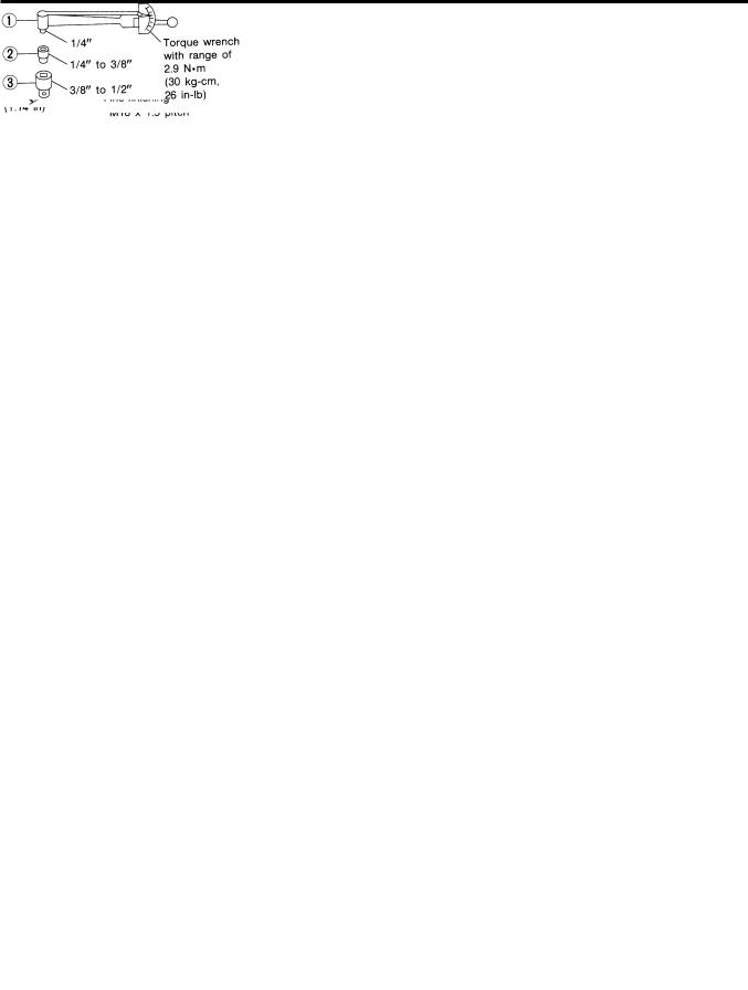
ST3127S000 |
Measuring turning torque |
|
1 GG91030000 |
|
|
Torque wrench |
|
|
2 HT62940000 |
|
|
Socket adapter |
|
|
3 HT62900000 |
|
|
Socket adapter |
|
|
|
NT541 |
|
|
|
ST-3
|
PREPARATION |
Commercial Service Tool |
|
|
|
|
Commercial Service Tool |
|
NJST0005 |
Tool number |
Description |
|
|
Oil pump attachment |
Disassembling and assembling oil pump |
|
Unit: mm (in) |
|
NT774 |
KV48105210 |
Removing and Installing power steering oil pump |
Sprocket holder |
|
NT809
ST-4
5-ST
Applicable :× |
|
|
Symptom |
|
|
and cause Possible PARTS SUSPECTED |
page Reference |
|
|
|
STEERING |
|
|
||
|
|
|
|
|
|
|
|
|
Judder |
Shimmy |
Vibration |
Shake |
Noise |
|
|
|
|
|
|
|
|
|
|
|
|
|
|
|
× |
Fluid level |
ST-7 |
|
|
|
|
|
|
|
|
|
|
|
|
|
× |
Air in hydraulic system |
ST-8 |
|
|
|
|
|
|
|
|
|
|
|
|
|
× |
Tie-rod ball joint swinging force |
ST-20 |
|
|
|
|
|
|
|
|
|
|
|
|
|
× |
Tie-rod ball joint rotating torque |
ST-20 |
|
|
|
|
|
|
|
|
|
|
|
|
|
× |
Tie-rod ball joint end play |
ST-20 |
|
|
|
|
|
|
|
|
|
|
|
|
|
× |
Steering gear fluid leakage |
ST-7 |
|
|
|
|
|
|
|
|
|
|
|
|
|
× |
Steering wheel play |
ST-6 |
|
|
|
|
|
|
|
|
|
|
|
|
|
× |
Steering gear rack sliding force |
ST-8 |
|
|
|
|
|
|
|
|
|
|
|
|
|
× |
Drive belt looseness |
Refer to EM-16. |
|
|
|
|
|
|
|
|
|
|
× |
× |
× |
|
Improper steering wheel |
Ð |
|
|
|
|
|
|
|
|
|
|
× |
× |
× |
|
Improper installation or looseness or tilt lock lever |
ST-11 |
|
|
|
|
|
|
|
|
|
× |
× |
× |
× |
|
Mounting rubber deterioration |
ST-6 |
|
|
|
|
|
|
|
|
|
|
|
× |
|
|
Steering column deformation or damage |
ST-15 |
|
|
|
|
|
|
|
|
|
|
|
× |
|
|
Improper installation or looseness of steering column |
ST-14 |
|
|
|
|
|
|
|
|
|
× |
× |
|
|
|
Steering linkage looseness |
ST-16 |
|
|
|
|
|
|
|
|
|
|
|
× |
× |
× |
DRIVE SHAFT |
AX-3 |
|
|
|
|
|
|
|
|
|
× |
× |
× |
× |
× |
AXLE |
AX-3 |
|
|
|
|
|
|
|
|
|
× |
× |
× |
× |
× |
SUSPENSION |
SU-4 |
|
|
|
|
|
|
|
|
|
× |
× |
× |
× |
× |
TIRES |
SU-4 |
|
|
|
|
|
|
|
|
|
× |
× |
|
× |
× |
ROAD WHEEL |
SU-4 |
|
|
|
|
|
|
|
|
|
× |
× |
|
× |
× |
BRAKES |
BR-7 |
|
|
|
|
|
|
|
|
Chart Troubleshooting NVH NJST0006S01 .parts these replace or repair necessary, If .symptom the of cause the find you help to below chart the Use |
Chart Troubleshooting NVH |
NJST0006 TROUBLESHOOTING (NVH) HARSHNESS AND VIBRATION NOISE, |
ON-VEHICLE SERVICE
Checking Steering Wheel Play
SST489B
SST490BA
Checking Steering Wheel Play
NJST0007
+ With wheels in a straight-ahead position, check steering wheel play.
Steering wheel play:
35 mm (1.38 in) or less
+If it is not within specification, check the following for loose or worn components.
Steering gear assembly
Steering column
Front suspension and axle
Checking Neutral Position on Steering Wheel
NJST0008
PRE-CHECKING
NJST0008S01
+ Make sure that wheel alignment is correct.
Wheel alignment: Refer to SU-14, SDS.
+ Verify that the steering gear is centered before removing the steering wheel.
CHECKING
NJST0008S02
1.Check that the steering wheel is in the neutral position when driving straight ahead.
2.If it is not in the neutral position, remove the steering wheel and reinstall it correctly.
3.If the neutral position is between two teeth, loosen tie-rod lock nuts. Turn the tie-rods by the same amount in opposite directions on both left and right sides.
SMA127
SST663B
Front Wheel Turning Angle
NJST0009
1.Rotate steering wheel all the way right and left; measure turning angle.
Turning angle of full turns: Refer to SU-14, SDS.
2. If it is not within specification, check rack stroke.
Rack stroke ªSº: Refer to SDS, ST-34.
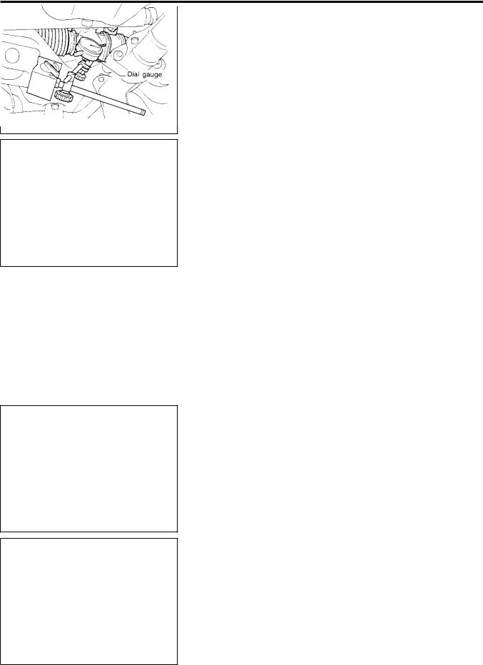
Checking Gear Housing Movement
NJST0010
1.Check the movement of steering gear housing during stationary steering on a dry paved surface.
+Apply a force of 49 N (5 kg, 11 lb) to steering wheel to check the gear housing movement.
Turn off ignition key while checking.
Movement of gear housing:
±2 mm (±0.08 in) or less
2.If movement exceeds the limit, replace mount insulator after confirming proper installation of gear housing clamps.
ST-6

ON-VEHICLE SERVICE
Checking and Adjusting Drive Belts
Checking and Adjusting Drive Belts
NJST0011
Refer to EM-16, ªChecking Drive Beltsº.
Checking Steering Gear and Linkage
NJST0037
STEERING GEAR
NJST0037S01
+Check gear housing and boots for looseness, damage or grease leakage.
+Check connection with steering column for looseness.
STEERING LINKAGE
NJST0037S02
+Check ball joint, dust cover and other component parts for looseness, wear, damage or grease leakage.
SMA851B
YST003
YST006
Checking Fluid Level
NJST0012
Check fluid level, referring to the scale on reservoir tank.
Use ªHOTº range for fluid temperatures of 50 to 80°C (122 to 176°F).
Use ªCOLDº range for fluid temperatures of 0 to 30°C (32 to 86°F).
CAUTION:
+Do not overfill.
+Recommended fluid is DEXRONTMIII or equivalent. Refer to MA-16, ªFluids and Lubricantsº.
Checking Fluid Leakage
NJST0013
Check the lines for improper attachment and for leaks, cracks, damage, loose connections, chafing and deterioration.
1.Run engine between idle speed and 1,000 rpm.
Make sure temperature of fluid in oil tank rises to 60 to 80°C (140 to 176°F).
2.Turn steering wheel right-to-left several times.
3.Hold steering wheel at each ªlockº position for five seconds and carefully check for fluid leakage.
CAUTION:
Do not hold the steering wheel in a locked position for more than 15 seconds.
4.If fluid leakage at connectors is noticed, loosen flare nut and then retighten.
Do not overtighten connector as this can damage O-ring, washer and connector.
5.If fluid leakage from power steering pump is noticed, check power steering pump. Refer to ST-25.
6.Check rack boots for accumulation of power steering fluid.
YST007
ST-7
ON-VEHICLE SERVICE
Bleeding Hydraulic System
Bleeding Hydraulic System
NJST0014
1.Raise front end of vehicle until wheels are clear of the ground.
2.Add fluid into oil tank to specified level. Then quickly turn steering wheel fully to right and left and lightly touch steering stoppers.
Repeat steering wheel operation until fluid level no longer decreases.
3.Start engine.
Repeat step 2. above.
+Incomplete air bleeding will cause the following to occur. When this happens, bleed air again.
a)Air bubbles in reservoir tank
b)Clicking noise in oil pump
c)Excessive buzzing in oil pump
Fluid noise may occur in the valve or oil pump. This is common when the vehicle is stationary or while turning the steering wheel slowly. This does not affect the performance or durability of the system.
SST491B
SST090B
Checking Steering Wheel Turning Force
NJST0015
1.Park vehicle on a level, dry surface and set parking brake.
2.Start engine.
3.Bring power steering fluid up to adequate operating temperature. [Make sure temperature of fluid is approximately 60 to 80°C (140 to 176°F).]
Tires need to be inflated to normal pressure.
4.Check steering wheel turning force when steering wheel has been turned 360° from the neutral position.
Steering wheel turning force: 39 N (4 kg, 9 lb) or less
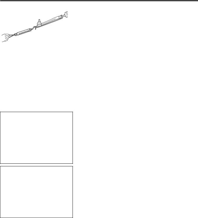
5.If steering wheel turning force is out of specification, check rack sliding force.
a.Disconnect steering column lower joint and knuckle arms from the gear.
b.Start and run engine at idle to make sure steering fluid has reached normal operating temperature.
c.Pull tie-rod slowly to move it from neutral position to ±11.5 mm (±0.453 in) at speed of 3.5 mm (0.138 in)/s. Check that rack sliding force is within specification.
Average rack sliding force: Sedan
152 - 240 N (15.5 - 24.5 kg, 34 - 54 lb) Hatchback
132 - 308 N (13.5 - 31.4 kg, 30 - 69 lb) Maximum force deviation:
Sedan
98 N (10 kg, 22 lb) Hatchback
176 N (17.9 kg, 39 lb)
d.Check sliding force outside the above range at rack speed of 40 mm (1.75 in)/s.
ST-8
ON-VEHICLE SERVICE
Checking Steering Wheel Turning Force (Cont'd)
Rack sliding force (Sedan only):
Not more than 294 N (30 kg, 66 lb) Maximum force deviation:
147 N (15 kg, 33 lb)
6.If rack sliding force is not within specification, overhaul steering gear assembly.
7.If rack sliding force is OK, inspect steering column. Refer to ST-14.
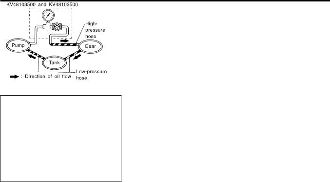
Checking Hydraulic System
NJST0016
Before starting, check belt tension, driving pulley and tire pressure.
1.Set Tool. Open shut-off valve. Then bleed air. Refer to ªBleeding Hydraulic Systemº, ST-8.
2.Run engine at idle speed or 1,000 rpm.
Make sure temperature of fluid in tank rises to 60 to 80°C (140 to 176°F).
WARNING:
Warm up engine with shut-off valve fully opened. If engine is
started with shut-off valve closed, fluid pressure in oil pump SST834-I increases to maximum. This will raise oil temperature abnor-
mally.
3.Check pressure with steering wheel fully turned to left and right positions with engine idling at 1,000 rpm.
CAUTION:
Do not hold the steering wheel in a locked position for more than 15 seconds.
Oil pump maximum standard pressure: QG15 engine (Sedan)
7,600 - 8,200 kPa (76.0 - 82.0 bar, 77.5 - 83.6 kg/cm2, 1,102 - 1,189 psi)
QG 18 engine (Sedan)
8,600 - 9,200 kPa (86.0 - 92.0 bar, 87.7 - 93.8 kg/cm2, 1,247 - 1,334 psi)
QG15, 18 engine (Hatchback)
8,600 - 9,200 kPa (86.0 - 92.0 bar, 88.7 - 93.8 kg/cm2, 1,247 - 1,334 psi)
YD22 engine
8,800 - 9,400 kPa (88.0 - 94.0 bar, 88.7 - 95.8 kg/cm2, 1,261 - 1,362 psi)
+If pressure reaches maximum operating pressure, system is OK.
+If pressure increases above maximum operating pressure, check power steering pump flow control valve. Refer to ST-25.
4.If power steering pressure is below the maximum operating pressure, slowly close shut-off valve and check pressure again.
CAUTION:
Do not close shut-off valve for more than 15 seconds.
+If pressure increases to maximum operating pressure, gear is damaged. Refer to ªRemoval and Installationº, ST-17.
+If pressure remains below maximum operating pressure, pump is damaged. Refer to ªDisassemblyº, ST-26.
5.After checking hydraulic system, remove Tool and add fluid as
ST-9

ON-VEHICLE SERVICE
Checking Hydraulic System (Cont'd)
necessary. Then completely bleed air out of system. Refer to ST-8.
ST-10

STEERING WHEEL AND STEERING COLUMN
Components
Components
NJST0017
JST875C
1. |
Air bag module |
5. |
Combination switch |
8. |
Hole cover |
2. |
Steering wheel |
6. |
Steering column assembly |
9. |
Lower joint |
3. |
Spiral cable |
7. |
Clip |
10. |
Lower cover |
4.Column cover
CAUTION:
+The rotation of the spiral cable (SRS ªAir bagº component part) is limited. If the steering gear must be removed, set the front wheels in the straight-ahead direction. Do not rotate the steering column while the steering gear is removed.
+Remove the steering wheel before removing the steering lower joint to avoid damaging the SRS spiral cable.
Removal and Installation
NJST0018
STEERING WHEEL
NJST0018S01
+ Remove air bag module and spiral cable.
Refer to RS-29, ªRemoval Ð Air Bag Module and Spiral Cableº.
SBF812E
ST-11
Loading...