


 Loading...
I BODY
SECTION SE
SEAT
A
B
C
D
CONTENTS
E
PRECAUTIONS ......................................................... |
3 |
Precautions for Supplemental Restraint System |
|
(SRS) “AIR BAG” and “SEAT BELT PRE-TEN- |
|
SIONER” ................................................................. |
3 |
Service Notice ......................................................... |
3 |
Precautions for Battery Service ............................... |
3 |
Precautions for Work ............................................... |
3 |
PREPARATION .......................................................... |
5 |
Special Service Tools .............................................. |
5 |
Commercial Service Tools ....................................... |
5 |
SQUEAK AND RATTLE TROUBLE DIAGNOSES..... |
6 |
Work Flow ............................................................... |
6 |
CUSTOMER INTERVIEW .................................... |
6 |
DUPLICATE THE NOISE AND TEST DRIVE ...... |
7 |
CHECK RELATED SERVICE BULLETINS .......... |
7 |
LOCATE THE NOISE AND IDENTIFY THE |
|
ROOT CAUSE ..................................................... |
7 |
REPAIR THE CAUSE .......................................... |
7 |
CONFIRM THE REPAIR ...................................... |
8 |
Generic Squeak and Rattle Troubleshooting .......... |
8 |
INSTRUMENT PANEL ......................................... |
8 |
CENTER CONSOLE ............................................ |
8 |
DOORS ................................................................ |
8 |
TRUNK ................................................................. |
9 |
SUNROOF/HEADLINING .................................... |
9 |
SEATS .................................................................. |
9 |
UNDERHOOD ...................................................... |
9 |
Diagnostic Worksheet ........................................... |
10 |
POWER SEAT/FOR COUPE ................................... |
12 |
Wiring Diagram–SEAT– /For Driver Seat .............. |
12 |
Wiring Diagram–SEAT– /For Passenger Seat ...... |
14 |
POWER SEAT/FOR ROADSTER ............................. |
15 |
ComponentPartsandHarnessConnectorLocation... |
15 |
System Description ............................................... |
16 |
DRIVER SIDE SEAT OPERATION .................... |
16 |
PASSENGER SIDE SEAT MANUAL OPERA- |
|
TION ................................................................... |
17 |
PASSENGER SEATBACK TILT FORWARD/ |
|
BACKWARD OPERATION ................................. |
18 |
INTERLOCKING OPERATION OF THE PAS- |
|
SENGER SEAT WITH THE SOFT TOP ............. |
19 |
PASSENGER SIDE RECLINING MOTOR |
|
OPERATION ........................................................ |
20 |
SEATBACK TILT CANCEL SWITCH OPERA- |
|
TION ................................................................... |
20 |
MANUAL OPERATION ....................................... |
21 |
AUTOMATIC OPERATION ................................. |
21 |
CANCEL FUNCTION ......................................... |
25 |
FAIL-SAFE MODE .............................................. |
25 |
Wiring Diagram–SEAT– / For Driver Seat ............. |
26 |
Schematic / For Passenger Seat ........................... |
28 |
Wiring Diagram–SEAT– / For Passenger Seat ...... |
29 |
TerminalsandReferenceValuesofPassengerSeat |
|
Control Unit ............................................................ |
34 |
Terminals and Reference Values of BCM .............. |
35 |
Terminals and ReferenceValues of SoftTopControl |
|
Unit ........................................................................ |
35 |
Terminals and Reference Values of Unified Meter |
|
and A/c Amp. ......................................................... |
36 |
Work Flow .............................................................. |
36 |
Trouble Diagnosis Symptom Chart ........................ |
36 |
BCM Power Supply and Ground Check ................ |
37 |
Driver Side Seat Power Supply and Ground Check... |
39 |
Driver Side Seat Sliding Motor Circuit Check ........ |
40 |
Driver Side Seat Reclining Motor Circuit Check .... |
41 |
Passenger Seat Control Unit Power Supply and |
|
Ground Check ....................................................... |
42 |
Passenger Seat Control Unit Ignition Signal Circuit |
|
Check .................................................................... |
43 |
Passenger Side Seat Sliding Motor Circuit Check... |
44 |
PassengerSideSeatRecliningMotorCircuitCheck... |
44 |
Passenger Side Seat Reclining Sensor Circuit |
|
Check .................................................................... |
45 |
Passenger Side Seat Sliding Switch Circuit Check... |
46 |
Passenger Side Seat Reclining Switch Circuit |
|
Check .................................................................... |
47 |
Passenger Side Power Seat Switch Ground Circuit |
|
Check .................................................................... |
48 |
Seatback Tilt Switch Circuit Check ........................ |
49 |
Seatback Tilt Cancel Switch Circuit Check ............ |
50 |
F
G
H
SE
J
K
L
M
Revision: 2005 August |
SE-1 |
2005 350Z |

Soft Top Switch Circuit Check ............................... |
51 |
PowerWindow DownRequest SignalCircuit ...Check 52 |
|
Storage Lid Close Signal Circuit Check ................. |
53 |
Soft Top Lock Switch Circuit Inspection ................. |
54 |
Seat Belt Buckle Switch Circuit Check .................. |
54 |
Vehicle Speed Signal Check ................................. |
56 |
HEATED SEAT ......................................................... |
57 |
Description ............................................................. |
57 |
Schematic .............................................................. |
58 |
Wiring Diagram–HSEAT–/For Coupe .................... |
59 |
Wiring Diagram–For Roadster– ............................. |
62 |
SEAT ........................................................................ |
65 |
Removal and Installation ....................................... |
65 |
MANUAL SEAT (COUPE) .................................. |
65 |
POWER SEAT .................................................... |
67 |
NET SEAT (ROADSTER) ................................... |
69 |
REMOVAL .......................................................... |
70 |
INSTALLATION ................................................... |
70 |
Disassembly and Assembly ................................... |
71 |
SEATBACK TRIM AND PAD (MANUAL SEAT |
|
AND POWER SEAT) .......................................... |
71 |
REMOVAL OF SEATBACK ASSEMBLY ............. |
71 |
INSTALLATION OF SEATBACK ASSEMBLY ..... |
71 |
SEATBACK TRIM AND PAD (NET SEAT FOR |
|
ROADSTER) ....................................................... |
72 |
SEATCUSHIONTRIMANDPAD(POWERSEAT |
|
AND NET SEAT) ................................................. |
74 |
SEAT CUSHION TRIM AND PAD (MANUAL |
|
SEAT FOR COUPE) ........................................... |
75 |
PASSENGER SIDE SEATBACK FORWARD |
|
RECLINING (COUPE) ........................................ |
76 |
PASSENGER SIDE SEATBACK FORWARD |
|
RECLINING (ROADSTER) ................................. |
76 |
Revision: 2005 August |
SE-2 |
2005 350Z |

|
PRECAUTIONS |
|
|
|
|
|
|
PRECAUTIONS |
PFP:00001 |
A |
|
Precautions for Supplemental Restraint System (SRS) “AIR BAG” and “SEAT |
|||
|
|||
BELT PRE-TENSIONER” |
AIS000I2 |
|
|
The Supplemental Restraint System such as “AIR BAG” and “SEAT BELT PRE-TENSIONER”, used along B with a front seat belt, helps to reduce the risk or severity of injury to the driver and front passenger for certain types of collision. This system includes seat belt switch inputs and dual stage front air bag modules. The SRS system uses the seat belt switches to determine the front air bag deployment, and may only deploy one front C air bag, depending on the severity of a collision and whether the front occupants are belted or unbelted. Information necessary to service the system safely is included in the SRS and SB section of this Service Manual.
WARNING: |
D |
|
●To avoid rendering the SRS inoperative, which could increase the risk of personal injury or death in the event of a collision which would result in air bag inflation, all maintenance must be per-
formed by an authorized NISSAN/INFINITI dealer.
●Improper maintenance, including incorrect removal and installation of the SRS, can lead to personal injury caused by unintentional activation of the system. For removal of Spiral Cable and Air
Bag Module, see the SRS section.
●Do not use electrical test equipment on any circuit related to the SRS unless instructed to in this Service Manual. SRS wiring harnesses can be identified by yellow and/or orange harnesses or harness connectors.
E
F
G
Service Notice |
AIS000I1 |
●When removing or installing various parts, place a cloth or padding onto the vehicle body to prevent
scratches. |
H |
|
●Handle trim, molding, instruments, grille, etc. carefully during removing or installing. Be careful not to oil or damage them.
●Apply sealing compound where necessary when installing parts.
●When applying sealing compound, be careful that the sealing compound does not protrude from parts.
●When replacing any metal parts (for example body outer panel, members, etc.), be sure to take rust pre-
vention measures.
Precautions for Battery Service |
AIS001PC |
Before disconnecting the battery, lower both the driver and passenger windows. This will prevent any interference between the window edge and the vehicle when the door is opened/closed. During normal operation, the window slightly raises and lowers automatically to prevent any window to vehicle interference. The automatic window function will not work with the battery disconnected.
Precautions for Work |
AIS000I3 |
SE
J
K
L
● When removing or disassembling each component, be careful not to damage or deform it. If a component |
M |
|
may be subject to interference, be sure to protect it with a shop cloth. |
||
|
●When removing (disengaging) components with a screwdriver or similar tool, be sure to wrap the component with a shop cloth or vinyl tape to protect it.
●Protect the removed parts with a shop cloth and keep them.
●Replace a deformed or damaged clip.
●If a part is specified as a non-reusable part, always replace it with new one.
●Be sure to tighten bolts and nuts securely to the specified torque.
●After re-installation is completed, be sure to check that each part works normally.
●Follow the steps below to clean components.
–Water soluble foul: Dip a soft cloth into lukewarm water, and wring the water out of the cloth to wipe the fouled area.
Then rub with a soft and dry cloth.
–Oily foul: Dip a soft cloth into lukewarm water with mild detergent (concentration: within 2 to 3%), and wipe the fouled area.
Then dip a cloth into fresh water, and wring the water out of the cloth to wipe the detergent off. Then rub with a soft and dry cloth.
Revision: 2005 August |
SE-3 |
2005 350Z |

PRECAUTIONS
●Do not use organic solvent such as thinner, benzene, alcohol, and gasoline.
●For genuine leather seats, use a genuine leather seat cleaner.
Revision: 2005 August |
SE-4 |
2005 350Z |

|
PREPARATION |
|
|
|
|
PREPARATION |
PFP:00002 |
|
Special Service Tools |
|
A |
AIS000I4 |
||
The actual shapes of Kent-Moore tools may differ from those of special service tools illustrated here.
Tool number |
|
|
|
|
B |
|
|
|
|
|
|
(Kent-Moore No.) |
|
Description |
|
|
|
Tool name |
|
|
|
|
|
|
|
|
|
|
C |
(J39570) |
|
|
|
|
|
|
Locating the noise |
|
|
D |
|
Chassis ear |
|
|
|
||
|
|
|
|
|
|
|
SIIA0993E |
|
|
|
E |
|
|
|
|
|
F |
(J43980) |
|
|
|
|
|
NISSAN Squeak and Rattle |
|
Repairing the cause of noise |
|
|
|
Kit |
|
|
|
|
|
|
|
|
|
|
G |
|
SIIA0994E |
|
|
|
|
|
|
|
|
|
|
Commercial Service Tools |
|
|
AIS000I5 |
||
|
|
|
|
|
H |
Tool name |
|
Description |
|
|
|
|
|
|
|
|
|
|
|
|
|
|
SE |
Engine ear |
|
Locating the noise |
|
|
|
|
|
|
|
||
|
|
|
|
|
J |
|
SIIA0995E |
|
|
|
|
|
|
|
|
|
K |
|
|
|
|
|
|
|
|
|
|
|
L |
|
|
|
|
|
M |
Revision: 2005 August |
SE-5 |
2005 350Z |

SQUEAK AND RATTLE TROUBLE DIAGNOSES
SQUEAK AND RATTLE TROUBLE DIAGNOSES
Work Flow
PFP:00000
AIS0066M
SBT842
CUSTOMER INTERVIEW
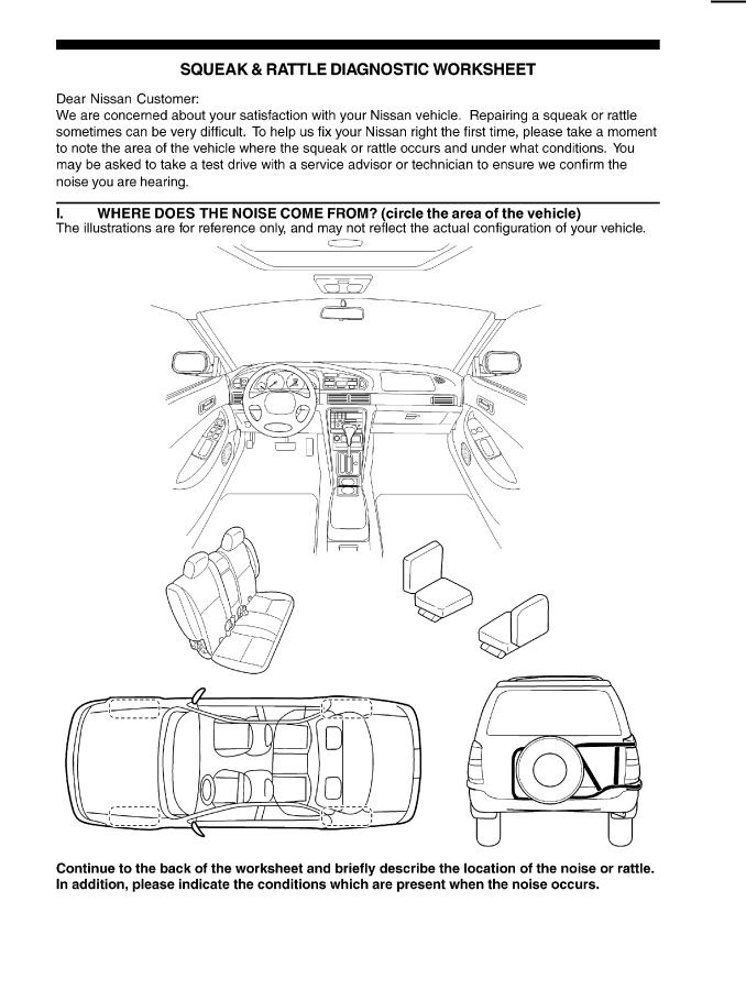
Interview the customer if possible, to determine the conditions that exist when the noise occurs. Use the Diagnostic Worksheet during the interview to document the facts and conditions when the noise occurs and any customer's comments; refer toSE-10, "Diagnostic Worksheet" . This information is necessary to duplicate the conditions that exist when the noise occurs.
●The customer may not be able to provide a detailed description or the location of the noise. Attempt to obtain all the facts and conditions that exist when the noise occurs (or does not occur).
●If there is more than one noise in the vehicle, be sure to diagnose and repair the noise that the customer is concerned about. This can be accomplished by test driving the vehicle with the customer.
●After identifying the type of noise, isolate the noise in terms of its characteristics. The noise characteristics are provided so the customer, service adviser and technician are all speaking the same language when defining the noise.
●Squeak —(Like tennis shoes on a clean floor)
Squeak characteristics include the light contact/fast movement/brought on by road conditions/hard surfaces=higher pitch noise/softer surfaces=lower pitch noises/edge to surface=chirping
●Creak—(Like walking on an old wooden floor)
Creak characteristics include firm contact/slow movement/twisting with a rotational movement/pitch dependent on materials/often brought on by activity.
●Rattle—(Like shaking a baby rattle)
Rattle characteristics include the fast repeated contact/vibration or similar movement/loose parts/missing clip or fastener/incorrect clearance.
●Knock —(Like a knock on a door)
Knock characteristics include hollow sounding/sometimes repeating/often brought on by driver action.
●Tick—(Like a clock second hand)
Tick characteristics include gentle contacting of light materials/loose components/can be caused by driver action or road conditions.
●Thump—(Heavy, muffled knock noise)
Thump characteristics include softer knock/dead sound often brought on by activity.
●Buzz—(Like a bumble bee)
Buzz characteristics include high frequency rattle/firm contact.
●Often the degree of acceptable noise level will vary depending upon the person. A noise that you may judge as acceptable may be very irritating to the customer.
●Weather conditions, especially humidity and temperature, may have a great effect on noise level.
Revision: 2005 August |
SE-6 |
2005 350Z |

SQUEAK AND RATTLE TROUBLE DIAGNOSES
DUPLICATE THE NOISE AND TEST DRIVE
If possible, drive the vehicle with the customer until the noise is duplicated. Note any additional information on the Diagnostic Worksheet regarding the conditions or location of the noise. This information can be used to duplicate the same conditions when you confirm the repair.
If the noise can be duplicated easily during the test drive, to help identify the source of the noise, try to duplicate the noise with the vehicle stopped by doing one or all of the following:
1)Close a door.
2)Tap or push/pull around the area where the noise appears to be coming from.
3)Rev the engine.
4)Use a floor jack to recreate vehicle “twist”.
5)At idle, apply engine load (electrical load, half-clutch on M/T models, drive position on A/T models).
6) Raise the vehicle on a hoist and hit a tire with a rubber hammer.
●Drive the vehicle and attempt to duplicate the conditions the customer states exist when the noise occurs.
●If it is difficult to duplicate the noise, drive the vehicle slowly on an undulating or rough road to stress the
vehicle body.
CHECK RELATED SERVICE BULLETINS
After verifying the customer concern or symptom, check ASIST for Technical Service Bulletins (TSBs) related to that concern or symptom.
If a TSB relates to the symptom, follow the procedure to repair the noise.
A
B
C
D
E
F
LOCATE THE NOISE AND IDENTIFY THE ROOT CAUSE
1.Narrow down the noise to a general area. To help pinpoint the source of the noise, use a listening tool (Chassis Ear: J-39570, Engine Ear and mechanics stethoscope).
2.Narrow down the noise to a more specific area and identify the cause of the noise by:
●removing the components in the area that you suspect the noise is coming from.
Do not use too much force when removing clips and fasteners, otherwise clips and fastener can be broken or lost during the repair, resulting in the creation of new noise.
●tapping or pushing/pulling the component that you suspect is causing the noise.
Do not tap or push/pull the component with excessive force, otherwise the noise will be eliminated only temporarily.
● feeling for a vibration with your hand by touching the component(s) that you suspect is (are) causing the noise.
● placing a piece of paper between components that you suspect are causing the noise.
● looking for loose components and contact marks.
Refer to SE-8, "Generic Squeak and Rattle Troubleshooting" .
G
H
SE
J
K
REPAIR THE CAUSE
●If the cause is a loose component, tighten the component securely.
●If the cause is insufficient clearance between components:
–separate components by repositioning or loosening and retightening the component, if possible.
–insulate components with a suitable insulator such as urethane pads, foam blocks, felt cloth tape or urethane tape. A Nissan Squeak and Rattle Kit (J-43980) is available through your authorized Nissan Parts Department.
CAUTION:
Do not use excessive force as many components are constructed of plastic and may be damaged.
NOTE:
Always check with the Parts Department for the latest parts information.
The following materials are contained in the Nissan Squeak and Rattle Kit (J-43980). Each item can be ordered separately as needed.
URETHANE PADS [1.5 mm (0.059 in) thick] |
|
|
Insulates connectors, harness, etc. |
|
|
76268-9E005: 100 × 135 mm (3.94 × 5.31 in)/76884-71L01: 60 × 85 mm (2.36 × |
3.35 in)/76884- |
|
71L02: 15 × 25 mm (0.59 × 0.98 in) |
|
|
INSULATOR (Foam blocks) |
|
|
Insulates components from contact. Can be used to fill space behind a panel. |
|
|
73982-9E000: 45 mm (1.77 in) thick, 50 × |
50 mm (1.97 × 1.97 in)/73982-50Y00: |
|
10 mm (0.39 in) thick, 50 × 50 mm (1.97 × |
1.97 in) |
|
Revision: 2005 August |
SE-7 |
2005 350Z |
L
M

SQUEAK AND RATTLE TROUBLE DIAGNOSES
INSULATOR (Light foam block)
80845-71L00: 30 mm (1.18 in) thick, 30 × 50 mm (1.18 × 1.97 in) FELT CLOTHTAPE
Used to insulate where movement does not occur. Ideal for instrument panel applications. 68370-4B000: 15 × 25 mm (0.59 × 0.98 in) pad/68239-13E00: 5 mm (0.20 in) wide tape roll The following materials, not found in the kit, can also be used to repair squeaks and rattles. UHMW (TEFLON) TAPE
Insulates where slight movement is present. Ideal for instrument panel applications. SILICONE GREASE
Used in place of UHMW tape that will be visible or not fit. Will only last a few months. SILICONE SPRAY
Use when grease cannot be applied. DUCT TAPE
Use to eliminate movement.
CONFIRM THE REPAIR
Confirm that the cause of a noise is repaired by test driving the vehicle. Operate the vehicle under the same conditions as when the noise originally occurred. Refer to the notes on the Diagnostic Worksheet.
Generic Squeak and Rattle Troubleshooting |
AIS0066N |
Refer to Table of Contents for specific component removal and installation information.
INSTRUMENT PANEL
Most incidents are caused by contact and movement between:
1.The cluster lid A and instrument panel
2.Acrylic lens and combination meter housing
3.Instrument panel to front pillar garnish
4.Instrument panel to windshield
5.Instrument panel mounting pins
6.Wiring harnesses behind the combination meter
7.A/C defroster duct and duct joint
These incidents can usually be located by tapping or moving the components to duplicate the noise or by pressing on the components while driving to stop the noise. Most of these incidents can be repaired by applying felt cloth tape or silicon spray (in hard to reach areas). Urethane pads can be used to insulate wiring harness.
CAUTION:
Do not use silicone spray to isolate a squeak or rattle. If you saturate the area with silicone, you will not be able to recheck the repair.
CENTER CONSOLE
Components to pay attention to include:
1.Shifter assembly cover to finisher
2.A/C control unit and cluster lid C
3.Wiring harnesses behind audio and A/C control unit
The instrument panel repair and isolation procedures also apply to the center console.
DOORS
Pay attention to the:
1.Finisher and inner panel making a slapping noise
2.Inside handle escutcheon to door finisher
3.Wiring harnesses tapping
4.Door striker out of alignment causing a popping noise on starts and stops
Tapping or moving the components or pressing on them while driving to duplicate the conditions can isolate many of these incidents. You can usually insulate the areas with felt cloth tape or insulator foam blocks from the Nissan Squeak and Rattle Kit (J-43980) to repair the noise.
Revision: 2005 August |
SE-8 |
2005 350Z |

SQUEAK AND RATTLE TROUBLE DIAGNOSES
TRUNK
Trunk noises are often caused by a loose jack or loose items put into the trunk by the owner. |
A |
In addition look for: |
|
1.Trunk lid dumpers out of adjustment
2. |
Trunk lid striker out of adjustment |
B |
|
||
3. |
The trunk lid torsion bars knocking together |
|
4. |
A loose license plate or bracket |
|
C
Most of these incidents can be repaired by adjusting, securing or insulating the item(s) or component(s) causing the noise.
SUNROOF/HEADLINING
Noises in the sunroof/headlining area can often be traced to one of the following:
1.Sunroof lid, rail, linkage or seals making a rattle or light knocking noise
2.Sunvisor shaft shaking in the holder
3.Front or rear windshield touching headlining and squeaking
Again, pressing on the components to stop the noise while duplicating the conditions can isolate most of these incidents. Repairs usually consist of insulating with felt cloth tape.
SEATS
D
E
F
When isolating seat noise it's important to note the position the seat is in and the load placed on the seat when |
G |
|||
the noise is present. These conditions should be duplicated when verifying and isolating the cause of the |
|
|||
noise. |
|
|||
Cause of seat noise include: |
H |
|||
1. |
Headrest rods and holder |
|||
|
||||
2. |
A squeak between the seat pad cushion and frame |
|
|
|
3. |
The rear seatback lock and bracket |
SE |
||
|
|
|
||
These noises can be isolated by moving or pressing on the suspected components while duplicating the conditions under which the noise occurs. Most of these incidents can be repaired by repositioning the component
or applying urethane tape to the contact area.
J
UNDERHOOD
Some interior noise may be caused by components under the hood or on the engine wall. The noise is then transmitted into the passenger compartment.
Causes of transmitted underhood noise include:
1.Any component mounted to the engine wall
2.Components that pass through the engine wall
3.Engine wall mounts and connectors
4.Loose radiator mounting pins
5.Hood bumpers out of adjustment
6.Hood striker out of adjustment
These noises can be difficult to isolate since they cannot be reached from the interior of the vehicle. The best method is to secure, move or insulate one component at a time and test drive the vehicle. Also, engine RPM or load can be changed to isolate the noise. Repairs can usually be made by moving, adjusting, securing, or insulating the component causing the noise.
K
L
M
Revision: 2005 August |
SE-9 |
2005 350Z |
SQUEAK AND RATTLE TROUBLE DIAGNOSES
Diagnostic Worksheet |
AIS0066O |
PIIB0723E
Revision: 2005 August |
SE-10 |
2005 350Z |
SQUEAK AND RATTLE TROUBLE DIAGNOSES
A
B
C
D
E
F
G
H
SE
J
K
L
M
SBT844
Revision: 2005 August |
SE-11 |
2005 350Z |

POWER SEAT/FOR COUPE
POWER SEAT/FOR COUPE
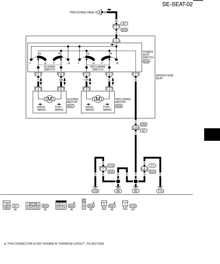
Wiring Diagram–SEAT– /For Driver Seat
PFP:87016
AIS004J0
TIWT0826E
Revision: 2005 August |
SE-12 |
2005 350Z |
POWER SEAT/FOR COUPE
A
B
C
D
E
F
G
H
SE
J
K
L
M
TIWT0723E
Revision: 2005 August |
SE-13 |
2005 350Z |

POWER SEAT/FOR COUPE
Wiring Diagram–SEAT– /For Passenger Seat
AIS004J1
TIWT0829E
Revision: 2005 August |
SE-14 |
2005 350Z |

POWER SEAT/FOR ROADSTER
POWER SEAT/FOR ROADSTER
Component Parts and Harness Connector Location
PFP:25565
A
AIS004J2
B
C
D
E
F
G
H
SE
J
K
L
M
PIIB1157E
Revision: 2005 August |
SE-15 |
2005 350Z |
POWER SEAT/FOR ROADSTER
System Description
Power is supplied at all times,
PIIA9747E
AIS004J7
●through 40A fusible link (letter F , located in the fusible link)
●to BCM terminal 55,
●through 10A fuse [No.18, located in the fuse block (J/B)]
●to BCM terminal 42,
●through 10A fuse [No.21, located in the fuse block (J/B)]
●to passenger seat control unit terminal 34,
●through BCM terminal 54
●to driver side power seat switch terminal 1 and passenger seat control unit terminal 39.
When ignition switch in ON or START position, power is supplied
●thought 10A fuse [No. 12, located in the fuse block (J/B)]
●to passenger seat control unit terminal 2.
When ignition switch in START position, power is supplied
●thought 10A fuse [No. 9, located in the fuse block (J/B)]
●to passenger seat control unit terminal 1.
Ground supplied
●to BCM terminal 52
●through body grounds M30 and M60,
●to power seat switch terminal 2 and
●to passenger side seat control unit terminals 40, 48
●through body grounds B5, B6 and T14.
DRIVER SIDE SEAT OPERATION
When a driver side seat sliding switch is operated forward, power is supplied
●through power seat switch terminal 5
●to sliding motor terminal 5.
Then ground is supplied
●to sliding motor terminal 6
●through power seat switch terminal 6
●through power seat switch terminal 2
The driver side seat moves forward.
When a driver side seat sliding switch is operated backward, power is supplied
●through power seat switch terminal 6
●to sliding motor terminal 6.
Then ground is supplied
●to sliding motor terminal 5
Revision: 2005 August |
SE-16 |
2005 350Z |

POWER SEAT/FOR ROADSTER
●through power seat switch terminal 5
●through power seat switch terminal 2
The driver side seat moves backward.
When a driver side seat reclining switch is operated forward, power is supplied
●through power seat switch terminal 3
●to reclining motor terminal 3.
Then ground is supplied
●to reclining motor terminal 4
●through power seat switch terminal 4
●through power seat switch terminal 2
The driver side seat folds forward.
When a driver side seat reclining switch is operated backward, power is supplied
●through power seat switch terminal 4
●to reclining motor terminal 4.
Then ground is supplied
●to reclining motor terminal 3
●through power seat switch terminal 3
●through power seat switch terminal 2 The driver side seat reclines backward.
PASSENGER SIDE SEAT MANUAL OPERATION
When a passenger side seat sliding switch is operated forward, ground is supplied
●to passenger seat control unit terminal 14
●through power seat switch terminal 14
●through power seat switch terminal 40B
●through body ground B5, B6 and T14.
Then passenger seat control unit recognizes the forward signal, power is supplied simultaneously
●through passenger seat control unit terminal 45
●to sliding motor terminal 45
Then ground is supplied
●to sliding motor terminal 37
●through passenger seat control unit terminal 37
The passenger side seat moves forward.
When a passenger side seat sliding switch is operated backward, ground is supplied
●to passenger seat control unit terminal 15
●through power seat switch terminal 15
●through power seat switch terminal 40B
●through body ground B5, B6 and T14.
Then passenger seat control unit recognizes the backward signal, power is supplied simultaneously
●through passenger seat control unit terminal 37
●to sliding motor terminal 37
Then ground is supplied.
●to sliding motor terminal 45
●through passenger seat control unit terminal 45 The passenger side seat moves backward.
Revision: 2005 August |
SE-17 |
A
B
C
D
E
F
G
H
SE
J
K
L
M
2005 350Z

POWER SEAT/FOR ROADSTER
When a passenger side seat reclining switch is operated forward, ground is supplied
●to passenger seat control unit terminal 12
●through power seat switch terminal 12
●through power seat switch terminal 40B
●through body ground B5, B6 and T14.
Then passenger seat control unit recognizes the forward signal, power is supplied simultaneously
●through passenger seat control unit terminal 42
●to reclining motor terminal 42
Then ground is supplied
●to reclining motor terminal 35
●through passenger seat control unit terminal 35
The passenger side seat folds forward.
When a passenger side seat reclining switch is operated backward, ground is supplied
●to passenger seat control unit terminal 13
●through power seat switch terminal 13
●through power seat switch terminal 40B
●through body ground B5, B6 and T14.
Then passenger seat control unit recognizes the back ward signal, power is supplied simultaneously
●through passenger seat control unit terminal 35
●to reclining motor terminal 35
Then ground is supplied
●to reclining motor terminal 42
●through passenger seat control unit terminal 42 The passenger side seat reclines backward.
PASSENGER SEATBACK TILT FORWARD/BACKWARD OPERATION
When a passenger side seatback tilt switch is operated forward, ground is supplied
●to passenger seat control unit terminal 8
●through seatback tilt switch terminal 8
●through seatback tilt switch terminal 40
●through body ground B5, B6 and T14.
Then passenger seat control unit recognizes the forward signal, power is supplied simultaneously
●through passenger seat control unit terminal 42
●to reclining motor terminal 42
Then ground is supplied
●to reclining motor terminal 35
●through passenger seat control unit terminal 35
Then, a seat folds front most forward.
When a passenger side seatback tilt switch is operated backward, ground is supplied
●to passenger seat control unit terminal 9
●through seatback tilt switch terminal 9
●through seatback tilt switch terminal 40
●through body ground B5, B6 and T14.
Then passenger seat control unit recognizes the backward signal,
Revision: 2005 August |
SE-18 |
2005 350Z |

POWER SEAT/FOR ROADSTER
power is supplied simultaneously
●through passenger seat control unit terminal 35
●to reclining motor terminal 35
Then ground is supplied
●to reclining motor terminal 42
●through passenger seat control unit terminal 42. The passenger side seat returns to former position.
INTERLOCKING OPERATION OF THE PASSENGER SEAT WITH THE SOFT TOP
NOTE:
Refer to RF-12, "System Description" for detailed operation. CLOSE → OPEN
When a soft top switch is operated to OPEN, ground is supplied
●to passenger seat control unit terminal 5
●through soft top switch terminal 3
●through soft top switch terminal 1
●through body ground M30 and M66.
Then passenger seat control unit recognizes the soft top OPEN signal,
Soft top control unit transmits power window down signal to passenger seat control unit,
●through soft top control unit terminal 36
●to passenger seat control unit terminal 16.
When passenger seat control unit receives power window down signal and soft top OPEN signal, power is supplied simultaneously
●through passenger seat control unit terminal 42
●to reclining motor terminal 42
Then ground is supplied
●to reclining motor terminal 35
●through passenger seat control unit terminal 35
Then, a seat folds 6° forward.
When storage lid closed, soft top control unit transmits a storage lid close signal to passenger seat control unit,
●through soft top control unit terminal 13
●to passenger seat control unit terminal 33.
When passenger seat control unit receives storage lid close signal, power is supplied simultaneously
●through passenger seat control unit terminal 35
●to reclining motor terminal 35
Then ground is supplied
●to reclining motor terminal 42
●through passenger seat control unit terminal 42.
The passenger side seat returns to former position. OPEN → CLOSE
When a soft top switch is operated to CLOSE, ground is supplied
●to passenger seat control unit terminal 6
●through soft top switch terminal 4
●through soft top switch terminal 1
●through body ground M30 and M66.
Then passenger seat control unit recognizes the soft top CLOSE signal,
soft top control unit transmits power window down signal to passenger seat control unit,
●through soft top control unit terminal 36
Revision: 2005 August |
SE-19 |
2005 350Z |
A
B
C
D
E
F
G
H
SE
J
K
L
M

POWER SEAT/FOR ROADSTER
●to passenger seat control unit terminal 16.
When passenger seat control unit receives power window down signal and soft top CLOSE signal, power is supplied simultaneously
●through passenger seat control unit terminal 42
●to reclining motor terminal 42
Then ground is supplied
●to reclining motor terminal 35
●through passenger seat control unit terminal 35
Then, a seat folds 6° forward.
When soft top lock switch (5th bow full latch switch) is turned ON, soft top control unit transmits a soft top lock signal to passenger seat control unit,
ground is supplied
●to passenger seat control unit terminal 11
●through soft top lock switch (5th bow full latch swtich) terminal 3
●through soft top lock switch (5th bow full latch swtich) terminal 4
●through body ground B5, B6 and T14.
When passenger seat control unit receives soft top lock switch ON signal, power is supplied simultaneously
●through passenger seat control unit terminal 35
●to reclining motor terminal 35
Then ground is supplied
●to reclining motor terminal 42
●through passenger seat control unit terminal 42. The passenger side seat returns to former position.
PASSENGER SIDE RECLINING MOTOR OPERATION
When a passenger side seat reclining motor is operated, signal is transmitted
●to passenger seat control unit terminal 3
●through reclining motor terminal 3
●through reclining motor terminal 41
●through passenger seat control unit terminal 41.
Then passenger seat control unit judges seatback angle by receiving reclining sensor signal.
SEATBACK TILT CANCEL SWITCH OPERATION
When a passenger side seatback tilt cancel switch is operated to CANCEL, ground is supplied
●to passenger seat control unit terminal 7
●through seatback tilt cancel switch terminal 7
●through seatback tilt cancel switch terminal 40C
●through body ground B5, B6 and T14.
Then passenger seat control unit recognizes the CANCEL signal.
When a “seatback tilt cancel switch” is operated to CANCEL, the automatic operation of a passenger seat is not performed.
Revision: 2005 August |
SE-20 |
2005 350Z |
POWER SEAT/FOR ROADSTER
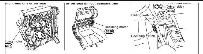
MANUAL OPERATION
The seat positions can be adjusted by operating the sliding switch and reclining switch located on the side of both driver and passenger seat cushions.
AUTOMATIC OPERATION
Passenger Seatback Tilting Function
●When theseatback tilt switch on the rear side of the passenger seatback is operated to tilt forward, the seatback tilts forward to the front most position.
●To tilt the seatback backward or restore its position, push the seatback tilt switch on the tilt-backward direction. The seatback will be tilting backwards while the switch is operated. It can be moved backwards until it reaches to its start position.
Conditions For the Operation
When the following conditions are satisfied, the seatback tilts forward or backward by operating the seatback tilt switch.
●Power seat switches (sliding and reclining) are OFF.
●The seat belt is not fastened.
●The vehicle speed is approximately 6 km/h or less.
Conditions
●The soft top is not currently in operation.*1
●The ignition switch is not in the START position.
●The seatback tilt cancel switch is in AUTO.
*1: The operation will be stopped only while the reclining motor is operating.
A
B
C
D
E
F
G
Conditions for Stopping the Operation
●Seatback tilting operation stops when any one of the conditions below is satisfied.
●A power seat switch (sliding or reclining) is operated.
|
● The seat belt is fastened. |
|
● The vehicle speed is approximately 7 km/h or more. |
Conditions |
● The soft top is in operation. (Stops only tilt-forward operation.)*2 |
|
● The seatback tilting switch is operated while the seatback is in operation. |
|
● The ignition switch is turned to the START position. |
|
● Reclining motor lock is detected. |
*2: Operation will be stopped only while the reclining motor is operating.
NOTE:
If operation stops as a result of the conditions below, use the reclining switch to tilt the seat backward.
●A power seat switch (sliding or reclining) is operated.
●The seat belt is fastened.
●The seatback tilt cancel switch is turned to “CANCEL”.
Soft Top Interlocking Operation Function
●The seatback tilts forward by approximately 6° (tilt froward operation) when the soft top opens or closes.
●When open/close operation is completed, the seatback returns to the tilt start position (return operation).
Conditions for the Operation
When the soft top switch is pushed to OPEN or CLOSE, and all of the conditions below are satisfied, then the seatback operates, linked with the operation of the soft top.
|
● The power seat switches (sliding and reclining) are OFF. |
|
● The seatback tilt switch is OFF. |
Conditions |
● The vehicle speed is 6 km/h or less. |
|
● The ignition switch is ON. |
|
● The seatback tilt cancel switch is turned to AUTO. |
|
|
Conditions for the Pauseing/Stopping Operation
Operation is paused or stopped if any of the conditions below are satisfied during soft top operation.
Revision: 2005 August |
SE-21 |
2005 350Z |
H
SE
J
K
L
M

POWER SEAT/FOR ROADSTER
●A power seat switch (sliding or reclining) is operated.
●Reclining motor lock is detected (return operation only).
Stop conditions
●The seatback tilt switch is operated while the seatback is operating.
●The seatback tilt cancel switch is turned to CANCEL.
Pause condition |
● The ignition switch is turned to the START position. |
Seat Status Output Signal
●Depending on the seat status, the “passenger seat control unit” sends the seat status output signal to the “soft top control unit”.
●The “soft top control unit” controls the soft top open/close operation based on whether the seat status signal is ON or OFF. For details about soft top control, refer to RF-19, "Operation Chart" .
●When a seatback tilt forward motion has been completed. (as a process during a soft top interlocking operation)
●When a seatback tilt forward motion has been completed. (during a automatic operation by using a seatback tilt switch)
●When a seatback tilt forward permission condition is satisfied for a soft top interlocking operation, and a tilt forward / backward operation is under going, and if the seatback is tilted more than 6 degree from the start position of the tilt forward / backward operation.
(during a automatic operation by using a seatback tilt switch)
Seat status signal
OFF→ ON condition ● When a seatback tilt forward permission condition is satisfied for a soft top interlocking operation, and a tilt forward operation was under going, but the operation was stopped under some conditions, (See below *4.)
and if the seatback is tilted more than 6 degree from the start position of the tilt forward operation. (after an automatic operation by using a seatback tilt switch)
●When a seatback tilt forward permission condition is satisfied for a soft top interlocking operation, and also the seatback tilt cancel switch is in “Cancel” position.
●When the ignition switch has been turned from “START” to “ON” position.
(during a soft top interlocking operation. After an engine start operation, the soft top interlocking operation is accepted.)
●When a seatback tilt backward motion has been started. (as a process during a soft top interlocking operation)
●When a seatback tilt backward permission condition is satisfied for a soft top interlocking operation, after a tilt forward operation has been finished.
(during a automatic operation by using a seatback tilt switch)
●When a seatback tilt backward permission condition is satisfied for a soft top interlocking operation, and a tilt forward / backward operation is under going, and if the seatback is tilted more than 6 degree from the start position of the tilt forward / backward operation.
(during a automatic operation by using a seatback tilt switch)
●When a seatback tilt backward permission condition is satisfied for a soft top interlocking operation, and a tilt
Seat status signal |
forward operation was under going, but the operation was stopped under some conditions, (See below *4.) |
ON→ OFF condition |
and if the seatback is still tilted more than 6 degree from the start position of the tilt forward operation. |
|
(after an automatic operation by using a seatback tilt switch.) |
●When the ignition switch has been turned from “ON” to “START” position.
(during a soft top interlocking operation. During an engine start operation, the soft top interlocking operation is paused.)
●When a seatback tilt forward motion has been started by the seatback tilt switch, just after the seatback tilt forward motion has been finished for a soft top interlocking operation.
(for the seatback tilt switch operation during a soft top interlocking operation)
●When a seatback tilt forward motion has been started by the passenger seat reclining switch, just after the seatback tilt forward motion has been finished for a soft top interlocking operation.
(for the seat reclining switch operation during a soft top interlocking operation)
*3: After that, seat condition signal stays ON if cancel switch turns to AUTO.
The seat status signal turns ON only when power window DOWN signal input is ON.
*4: If tilt forward/backward operation stops as a result of the conditions below, the tilt start position does not change.
●The vehicle speed is approximately 7 km/h or more.
●The seatback tilt switch is operated while the seatback is operating.
●The ignition switch is turned to the START position.
Revision: 2005 August |
SE-22 |
2005 350Z |

POWER SEAT/FOR ROADSTER
Operation of the Passenger Seat Linked with the Soft Top
A
B
C
D
E
F
G
H
SE
J
K
L
M
PIIA7847E
Revision: 2005 August |
SE-23 |
2005 350Z |
Loading...