

Nikon AF-S DX NIKKOR 18-200mm Repair manual

作成承認印 配布許可印
INC
AF-S VR DX Zoom Nikkor
18-200/3.5-5.6G ED
JAA79471-R.3678.A
JAA79471
JAA79451
REPAIR MANUAL
(MADE IN JAPAN)
(MADE IN THAILAND)
Printed in Japan Dec 2005
Copyrighc2005 by Nikon Corporation.
All Rights Reserved.
無断転載を禁ず
!!

JAA79471-R.3678.A
INC
Specications
Type of lens: G-type AF-S DX VR Zoom-Nikkor lens having built-in CPU and Nikon
bayonet mount [Specially designed for use with the Nikon digital SLR cameras
(Nikon DX format)]
Focal length: 18mm–200mm
Maximum aperture: f/3.5–5.6
Lens construction: 16 elements in 12 groups (3 aspherical lens and 2 ED lens elements)
Picture angle: 76°– 8°
Focal length scale: 18, 24, 35, 50, 70, 135, 200mm
Distance information: Output to camera body
Zoom control: Manually via separate zoom ring
Focusing: Nikon Internal Focusing (IF) system (utilizing an internal Silent
Wave Motor); manually via separate focus ring
Vibration reduction: Lens-shift method using voice coil motors (VCMs)
Shooting distance scale: Graduated in meters and feet from 0.5m (3 ft.) to innity ( ‡)
Closest focus distance: 0.5m (1.6 ft.) at all zoom settings
No. of diaphragm blades: 7 pcs. (rounded)
Diaphragm: Fully automatic
Aperture range: f/3.5 to f/22 (at 18mm), f/5.6 to f/36 (at 200mm)
Exposure measurement: Via full-aperture method
Attachment size: 72mm (P = 0.75mm)
Dimensions: Approx. 77mm dia. x 96.5mm extension from the camera’s lens mount ange
Weight: Approx. 560g (19.8 oz)
- M1
AF-S VRDX 18-200/3.5-5.6G -
・

JAA79471-R.3678.A
INC
※ Before Disassembly / (Re)assembly / Adjustment
On this lens, the VR (vibration-reduction) unit is mounted to correct the picture blur.
In order to maintain the functional accuracy of the picture blur correction, if detaching the VR
(vibration-reduction) unit and gyro base plate or if removing the main PCB unit, be sure to adjust the VR by
using the VR lens adjustment equipment (J15380).
However, if disassembling the parts except the above, the VR adjustment is NOT necessary.
At service agencies where the "VR lens adjustment equipment" is not prepared, do NEITHER disassemble
NOR repair the products of the above case.
Caution:
① When disassembling, make sure to memorize the processing state of wires, screws to be xed and their types, etc.
② Because prototypes are used for "Disassembly/(Re)assembly/Adjustment", they may differ from the actual
products in forms, etc.
③ Because pictures are processed by a special method, they may differ from the actual ones in texture.
Points to notice for Lead-free solder products
・Lead-free solder is used for this product.
・For soldering work, the special solder and soldering iron are required.
・Do NOT mix up lead-free solder with traditional solder.
・Use the special soldering iron respectively for lead-free solder and lead solder.
They cannot be used in common.
- D1・ AF-S VRDX18-200/3.5-5.6G -
1. Disassembly
INC
JAA79471-R.3678.A
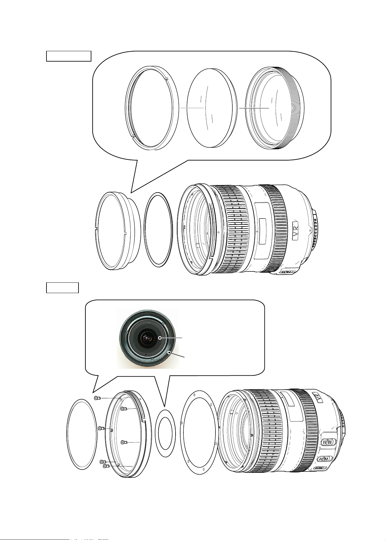
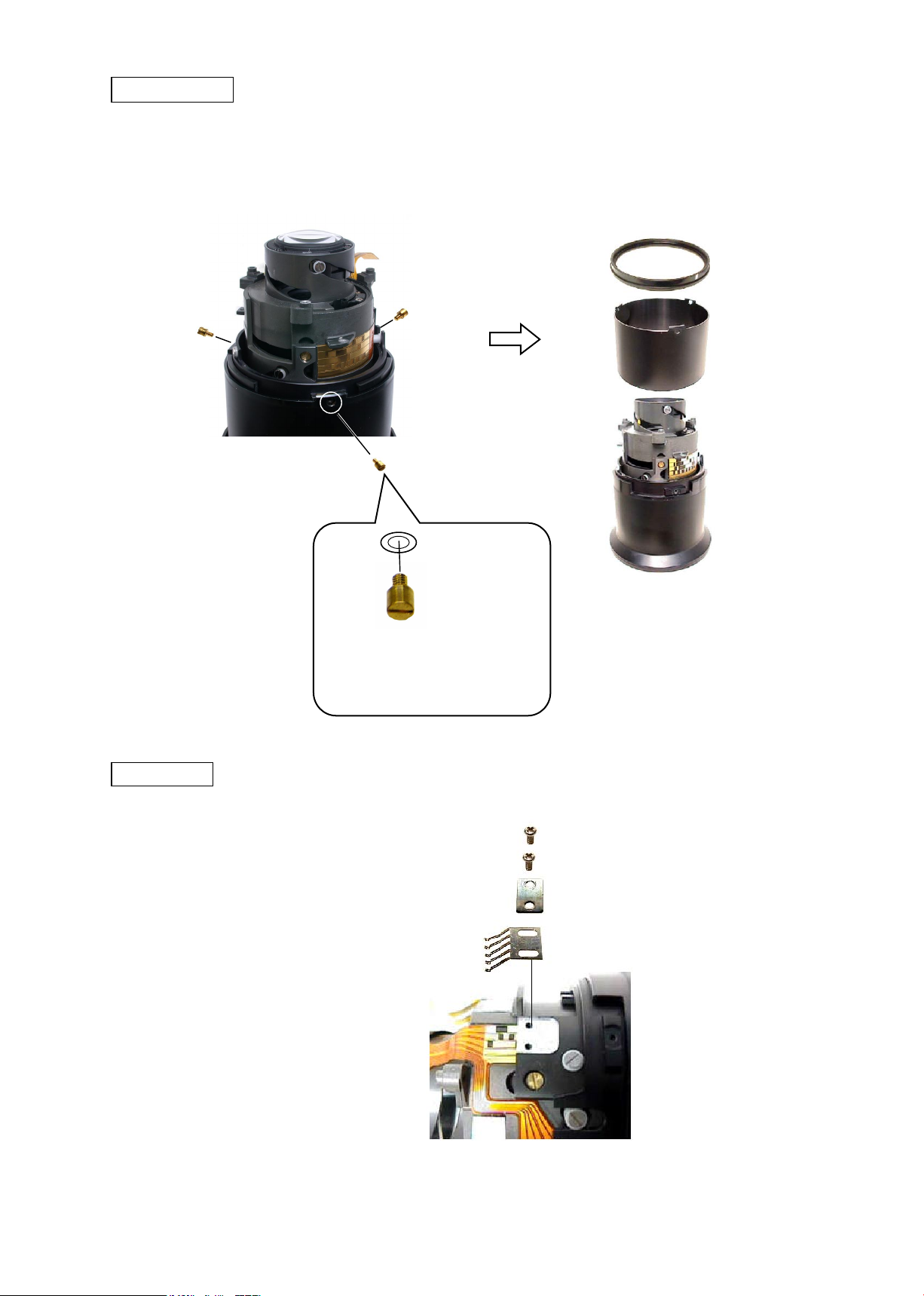
1st lens group
Retaining ring (#42)
#133
G1-2 cemented lens
1st lens group (B0006)
Filter ring
#60
Cover ring (#62)
1st lens-group cover ring
(#60)
#128×6
#62
#100
Filter ring
- D2・ AF-S VRDX18-200/3.5-5.6G -
JAA79471-R.3678.A
INC
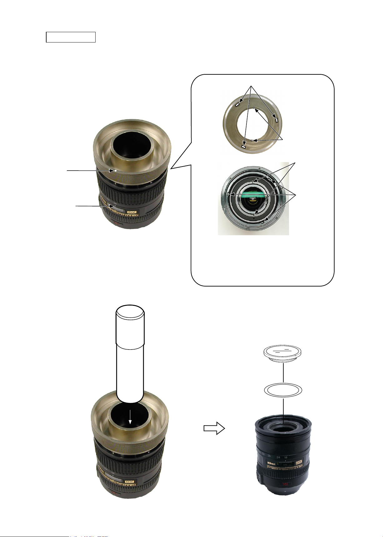
2nd lens group
★
New Tool
① Set the lens zoom position to 18, while the focus ring to "∞" position.
② Mount the 2nd lens-group retaining tool ( J11318) on the lens by aligning the indexes with each other.
Index
Index
★
Convex portion×3
2nd lens-G retaining
tool (J11318)
★
J11318
Pin×2
Hole×2
Groove×3
Enter the three convex portions of (J11318) into the three
grooves of (J11318), while two pins into the two holes of the
lens.
Caution)
focus ring little by little, then align the pins with the holes.
Remove the 2nd lens-group and the washer (#80) by using the wrench ( J11317).
③
★
If the positions of pins do not match, turn the
J11317
★
2nd lens group
Washer (#80A~K)
- D3・ AF-S VRDX18-200/3.5-5.6G -
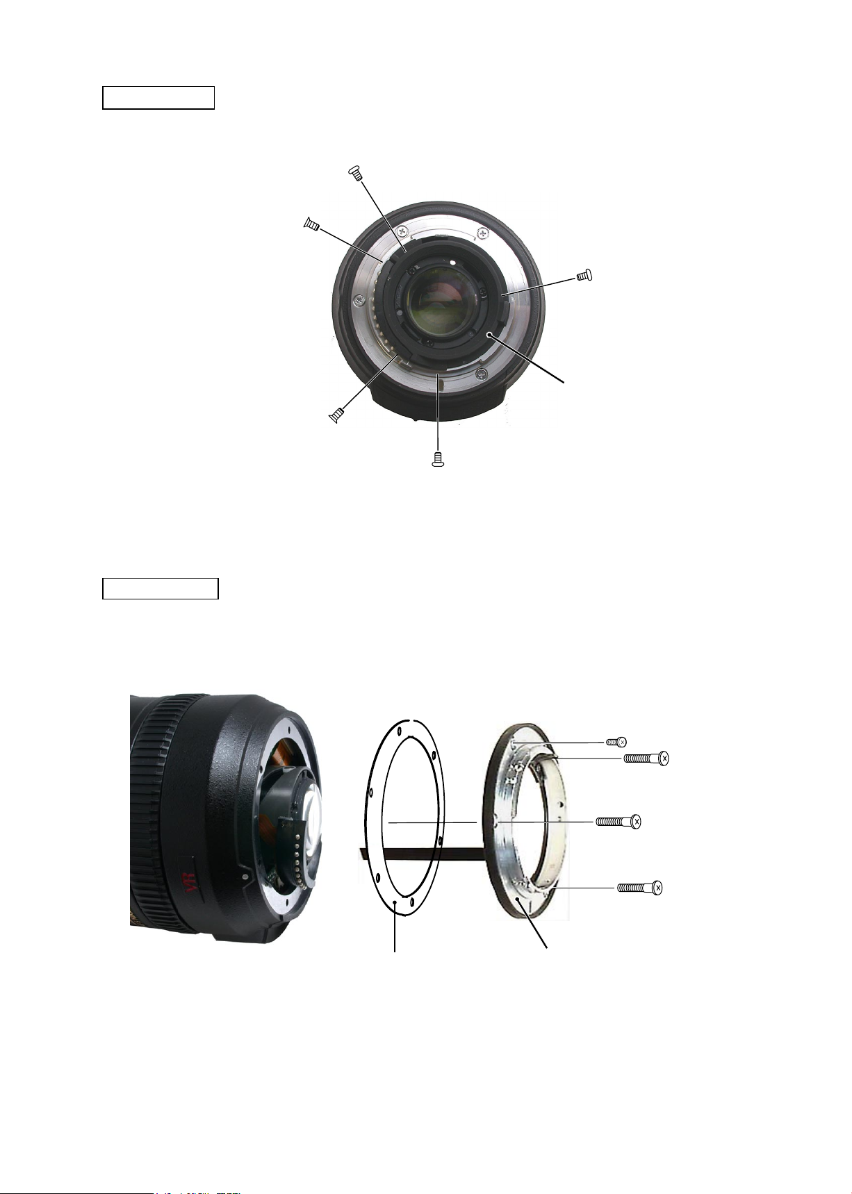
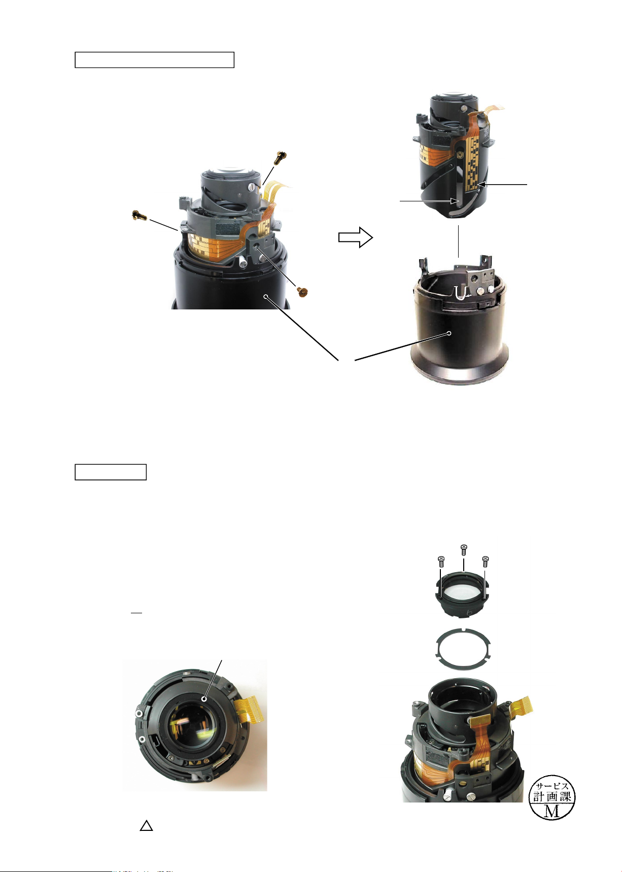
Rear cover ring
INC
JAA79471-R.3678.A
#118×3
#117×2
Rear cover ring
Bayonet mount
#79
#114
#115×3
Bayonet mount
- D4・ AF-S VRDX18-200/3.5-5.6G -
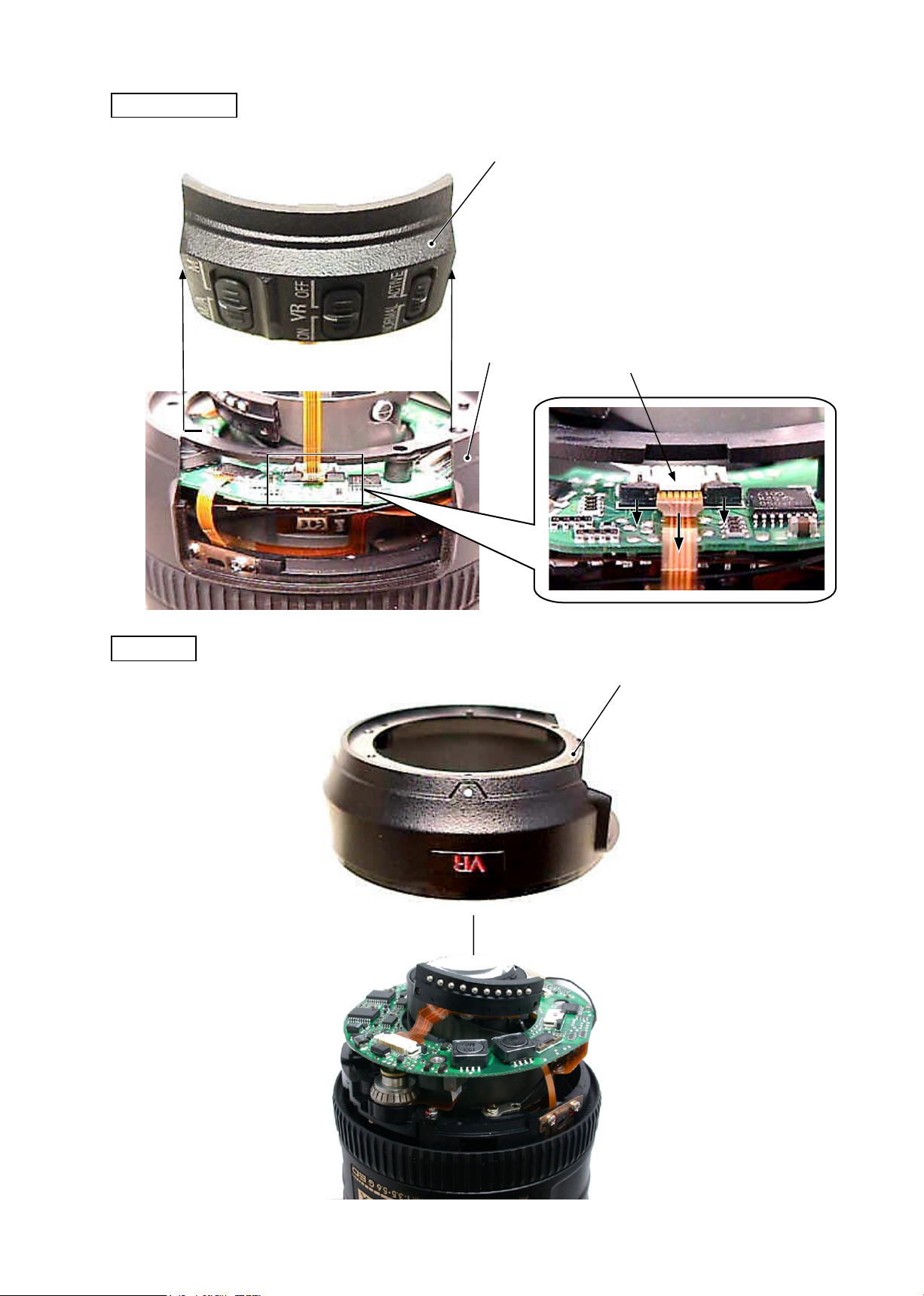
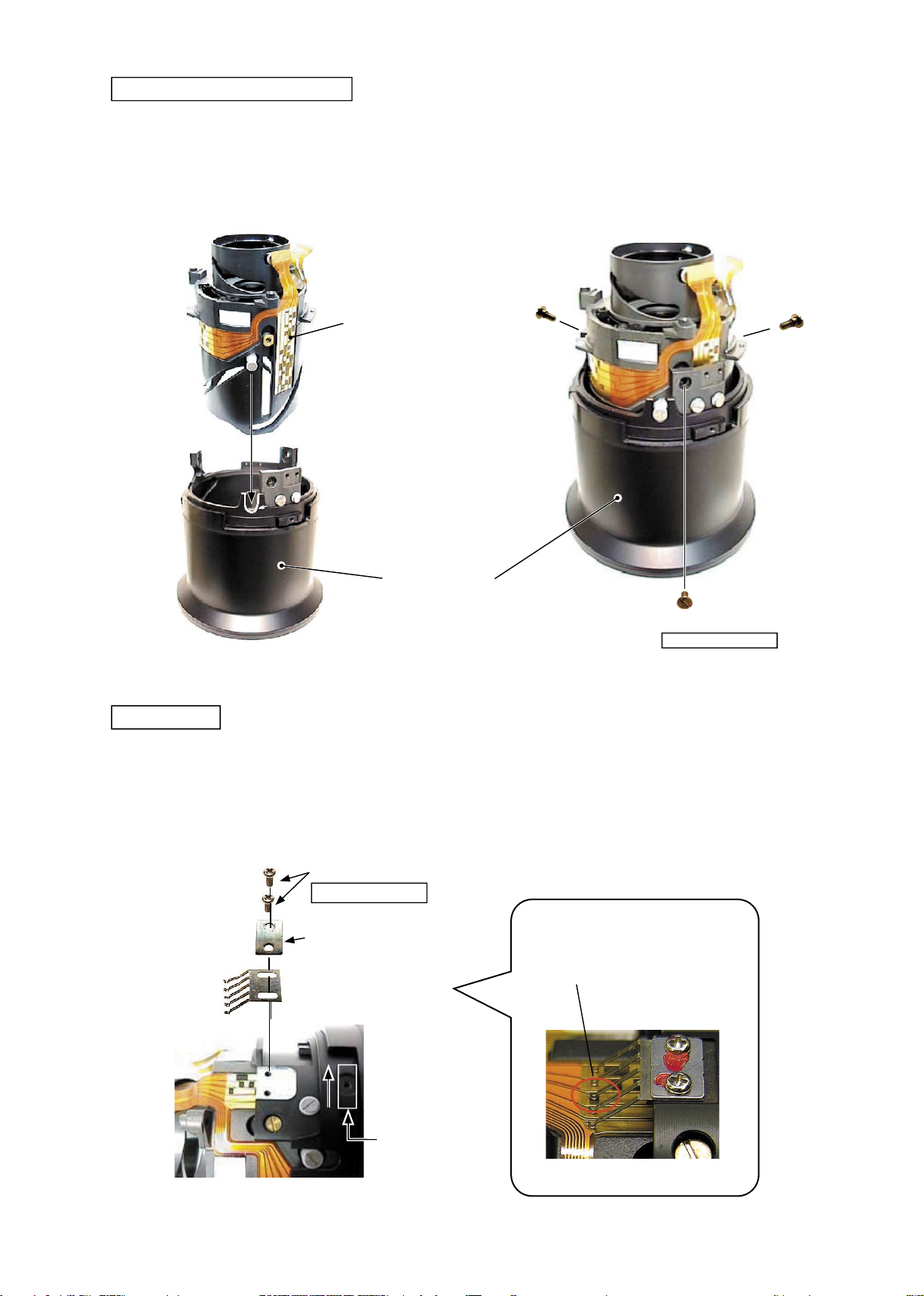
Change-SW unit
INC
While holding the rear cover by hand, remove the change-SW unit.
・
Change-SW unit
JAA79471-R.3678.A
Rear cover
Rear cover
(B1001) connector unit
Rear cover
- D5・ AF-S VRDX18-200/3.5-5.6G -
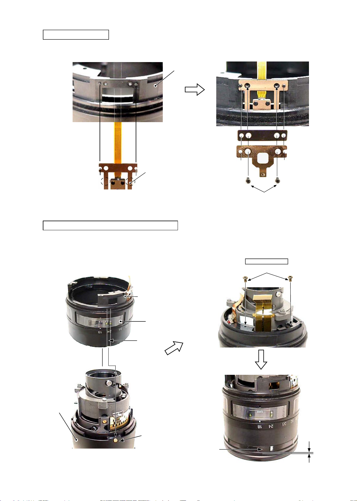
Contacts unit
INC
Remove the FPC of the contacts unit from the connector.
・
Contacts unit
Connector
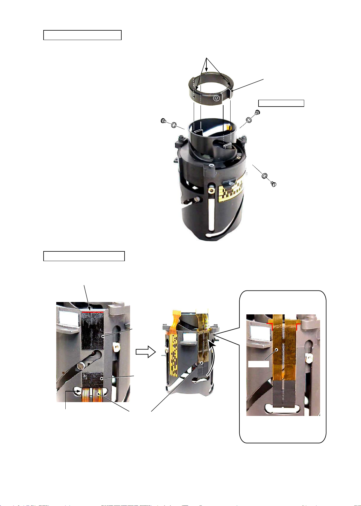
Main PCB unit
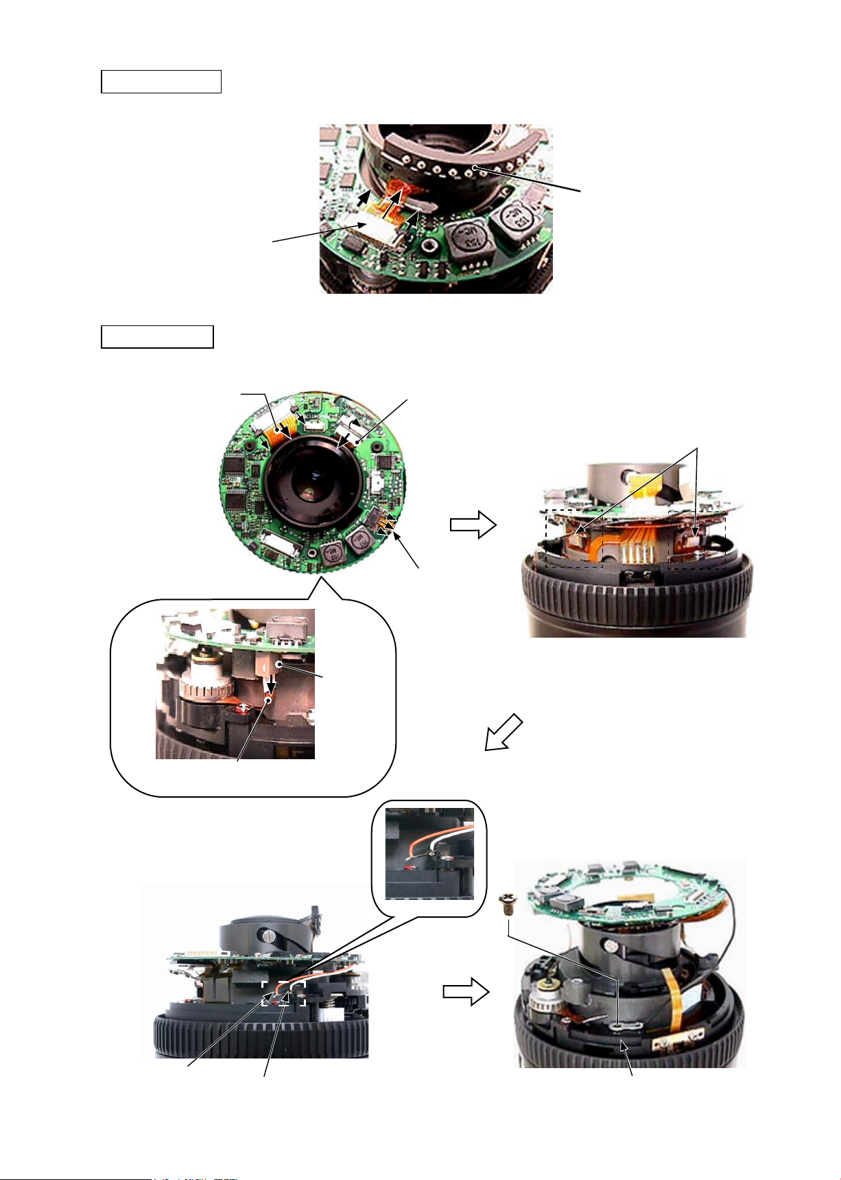
Remove the VR FPC, encoder FPC, GMR sensor, and SWM-FPC from each connector.
①
JAA79471-R.3678.A
VR FPC
SWM FPC
Connector
Encoder FPC
GMR sensor FPC
Remove the gyro-FPC from the body.
②
Gyro-FPC
Remove the two wires from the
③
SWM unit.
Orange
White
Remove the main PCB unit by taking
④
#123
- D6・ AF-S VRDX18-200/3.5-5.6G -
out the screw (#123) of lug plate.
Lug plate
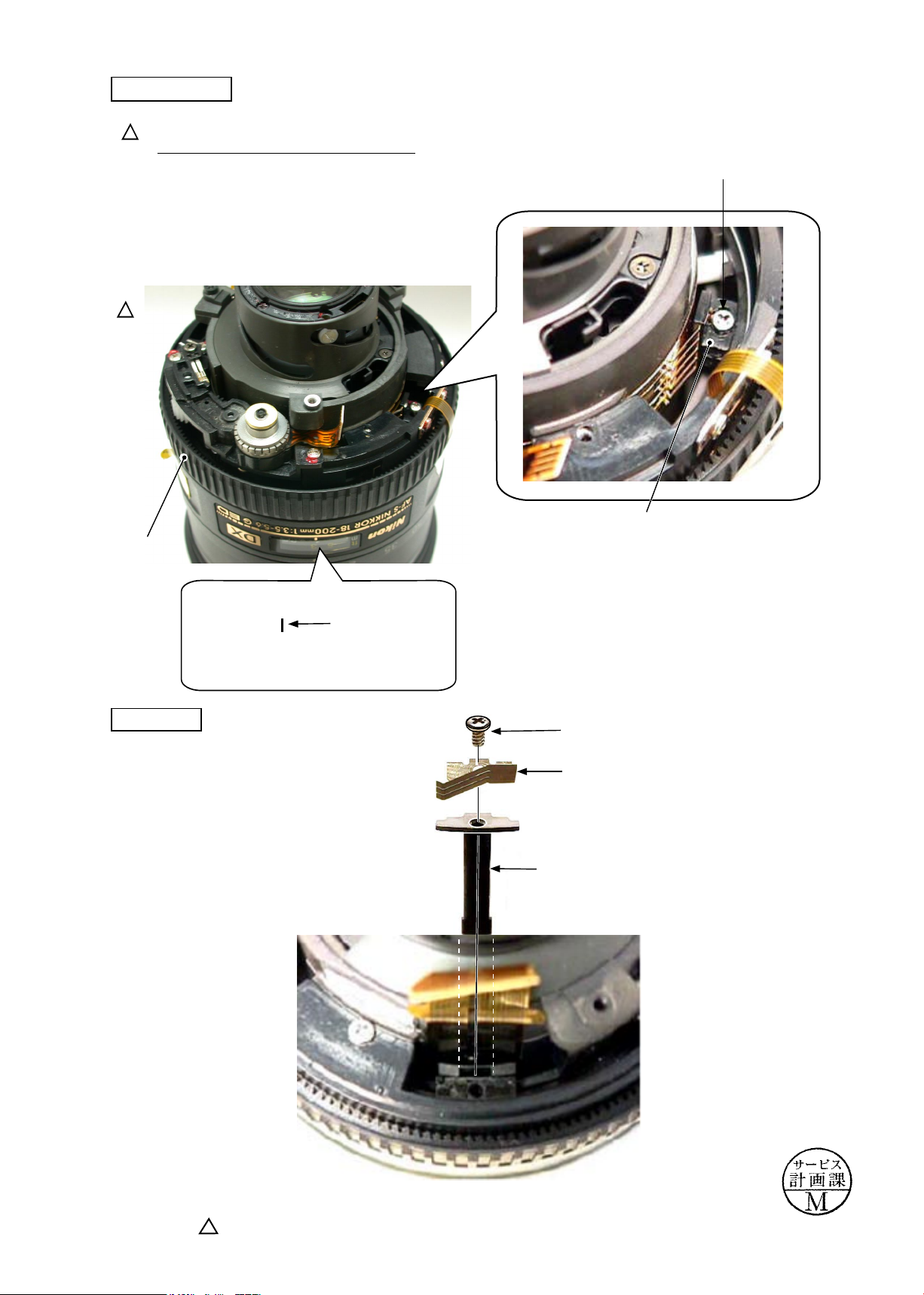
Distance-brush
INC
JAA79471-R.3678.A
Revision
(
Rotate the focusing ring to "close"-end.
①
Take out the screw (#112) to remove the distance-brush.
②
Revision
(
MF ring
Rotate the MF ring, and set the distance scale to "1 m".
)
)
#112
Distance-brush
Focus key
Position where the distance-brush must be
removed
1
Distance scale
(Reference line)
#122
#157
Focus key
Changed page
× 2
- D7・ AF-S VRDX18-200/3.5-5.6G -
March. 17. 2006
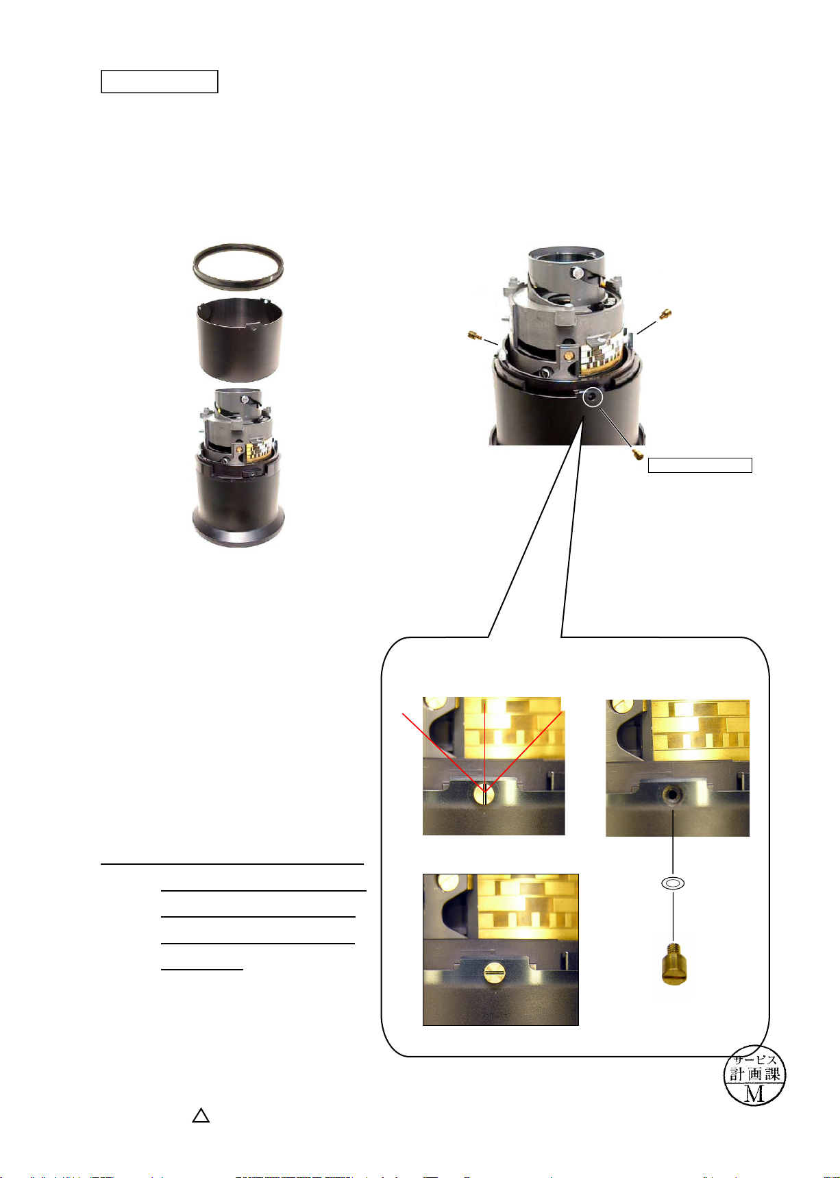
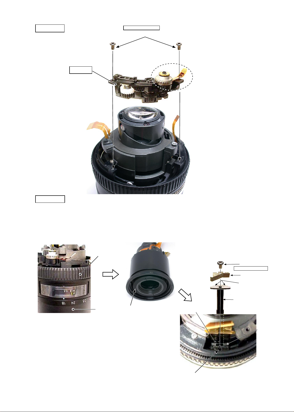
SWM unit
INC
JAA79471-R.3678.A
#154×2
Be careful NOT to touch A-part directly
SWM unit
by hand.
A-part
MF-ring, Rubber ring
MF-ring
Rubber ring
- D8・ AF-S VRDX18-200/3.5-5.6G -
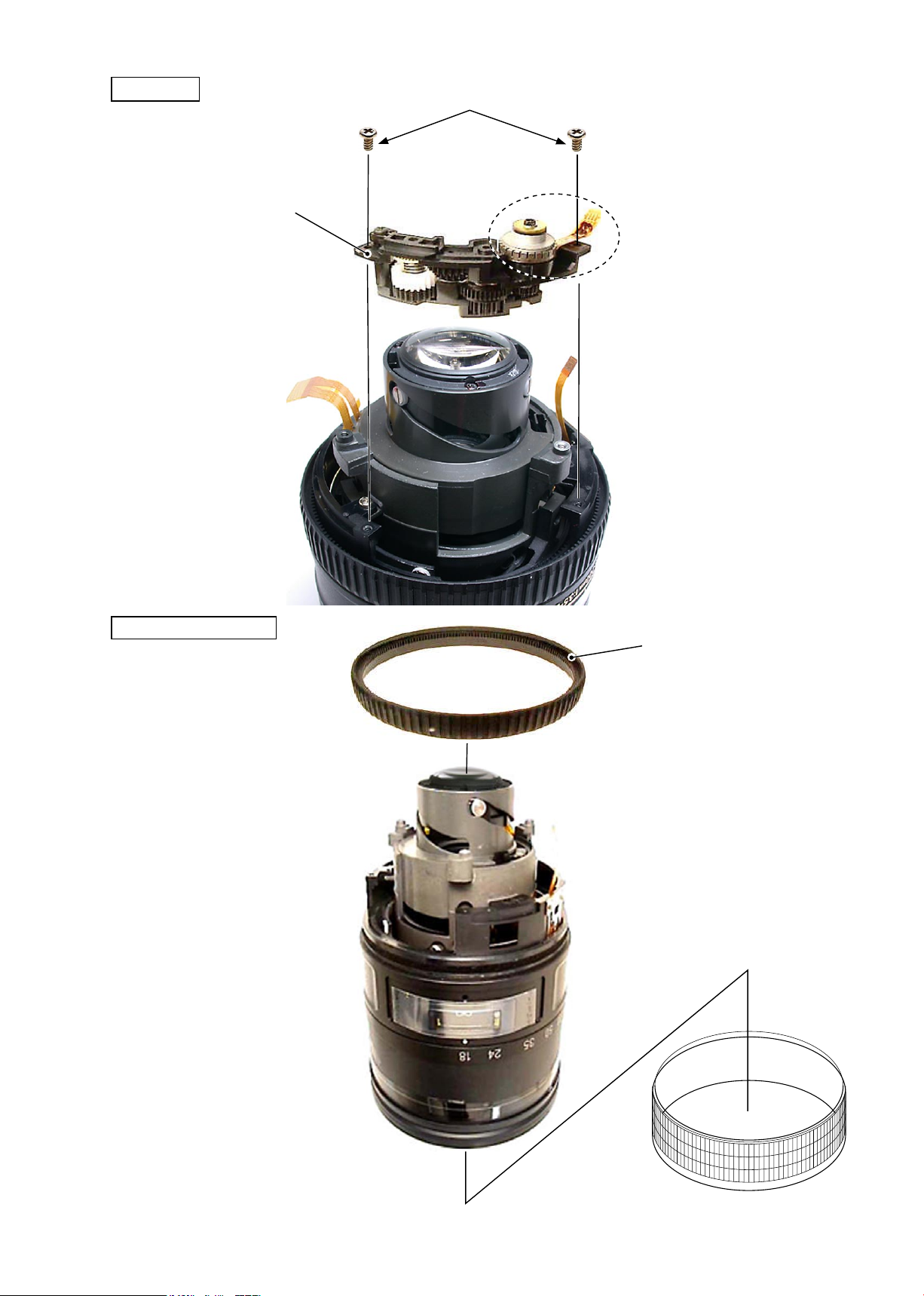
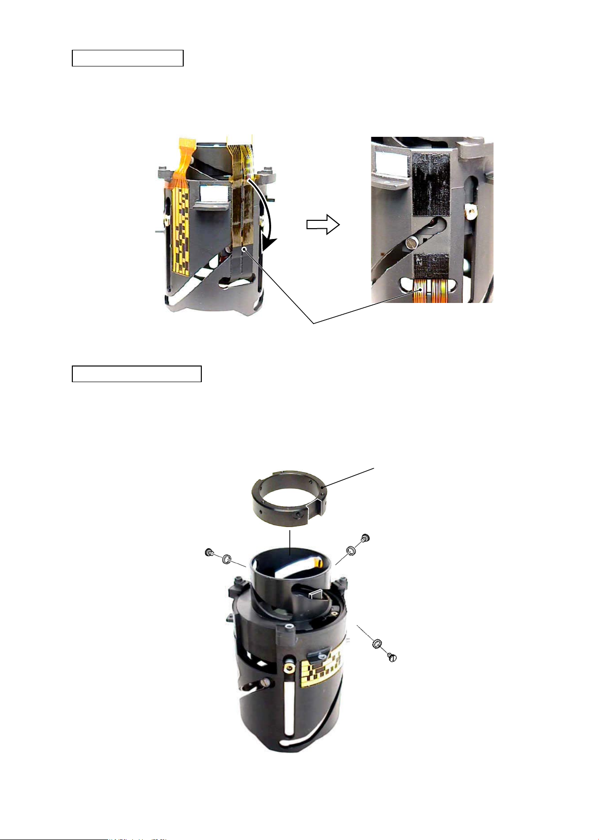
Removal of Zoom index ring unit from Lens body
INC
JAA79471-R.3678.A
① Remove the polyester tape.
Polyester tape
② Take out two screws (#123).
#123×2
Rotate the gear unit and set to "close"-side.
③
Remove the zoom index unit from the lens body.
④
Gear unit
Zoom index ring unit
Lens body
- D9・ AF-S VRDX18-200/3.5-5.6G -

GMR sensor FPC unit
INC
JAA79471-R.3678.A
#97
#122×2
#130
Caution:
When the GMR sensor FPC unit is removed, do
NOT bend the area of doted lines.
GMR sensor
FPC unit
Zoom index ring
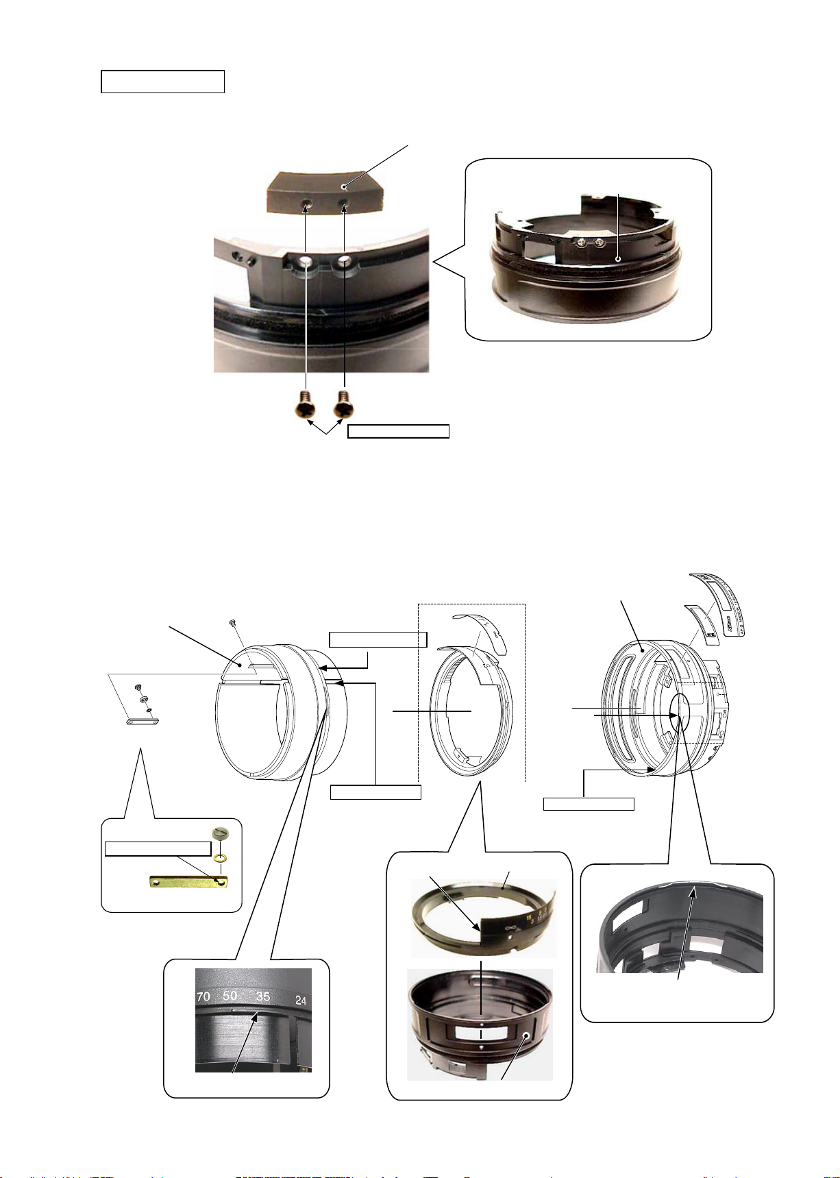
Take out the screw (#144) and remove the lens zoom control key.
①
Rotate the zoom ring by slightly exceeding its index "18-200", and remove the zoom ring from the zoom
②
index ring.
#144
Zoom ring
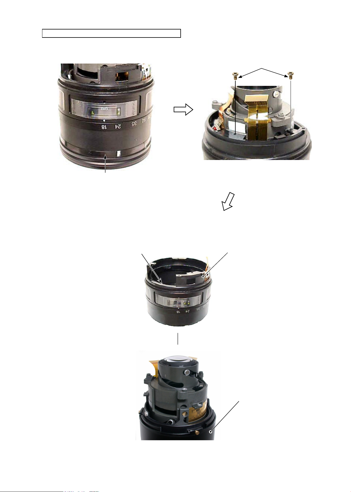
Distance scale sticker
Gear unit
Zoom index ring
#155
Name plate
#76
Zoom control key
Rotate so that the edge of "∞" side of the distance
③
scale sticker is aligned with the index of the
zoom index ring, and remove the gear unit.
Take out two screws (#112), and remove the block
④
(#155).
- D10 ・ AF-S VRDX18-200/3.5-5.6G -
#112×2
Edge
Gear unit
Index
Zoom index ring
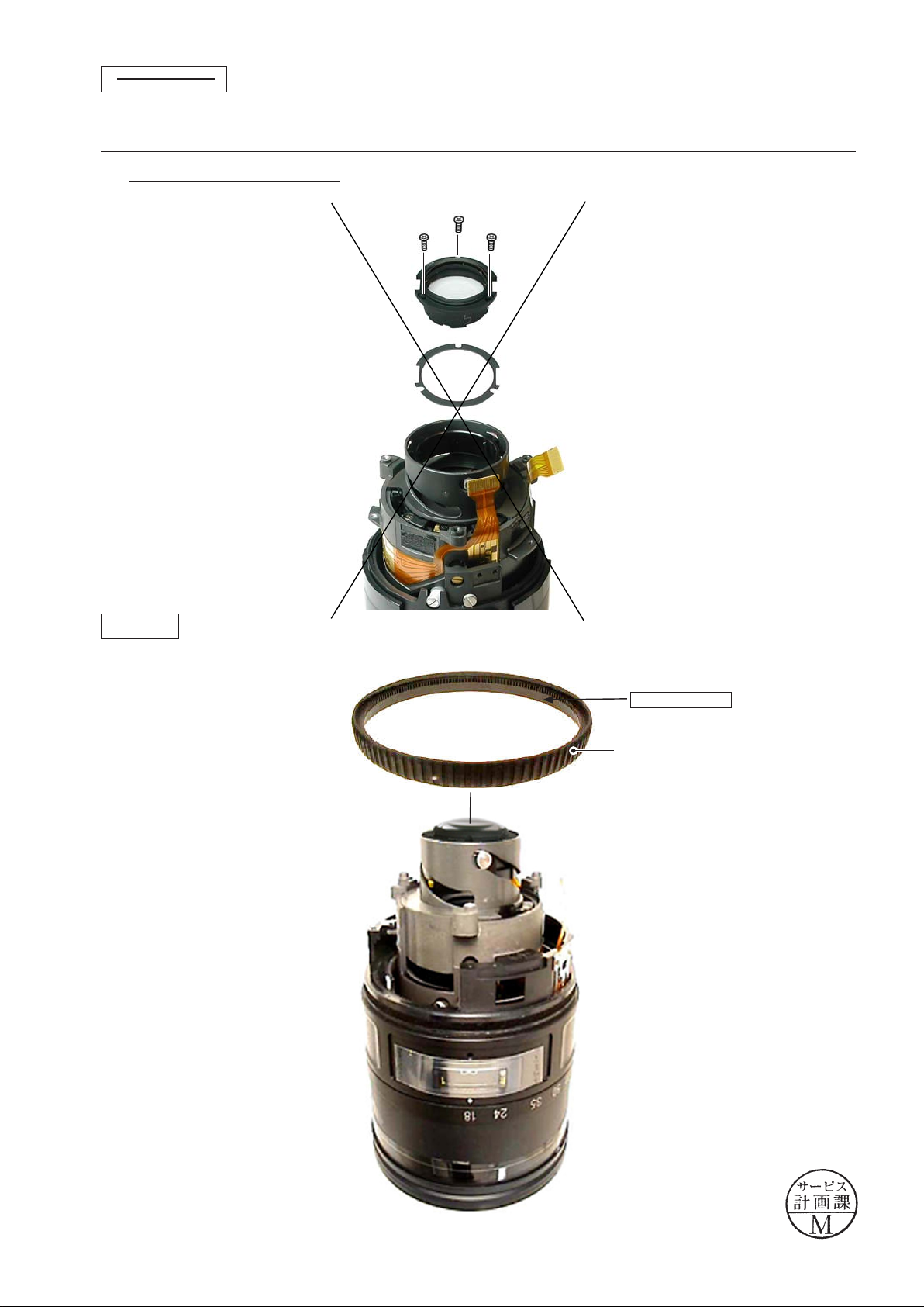
Cover ring unit
INC
Take out three screws (#110), and remove the reinforcing ring unit and cover ring unit.
・
#110×3
JAA79471-R.3678.A
Reinforcing ring
unit
Cover ring unit
In some cases, the
adjustment washer (#107)
is put in.
Zoom brush
Take out two screws (#109) and remove the
・
zoom brush.
#107
#110
#109×2
#106
Zoom brush
- D11 ・ AF-S VRDX18-200/3.5-5.6G -
JAA79471-R.3678.A
- D12 ・ AF-S VRDX18-200/3.5-5.6G -
Caution:
The 2nd lens-G straight ring unit must not be disassembled any further at service facilities, because if it is,
special tools and several selected rollers become necessary for assembly.
Caution:
When the 4th lens group is removed, it becomes necessary to perform lens alignment work after assembly.
・
Remove the 4th lens-G cover ring (#70).
・
Take out three screws (#124), and remove the 4th lens group and
washer (#13).
#70
4th lens group
#139A~H
#124×3
・
Take out three screws (#67), and remove the 2nd lens-group straight
ring unit.
4th lens group
2nd lens-group straight ring unit
2nd lens-G straight ring unit
#67×3
#68×3
#99
At service facilities where the alignment work is impossible, do
not remove the 4th lens group.
Changed page
× 1
March. 17. 2006
#139
△ (Revision)
INC
Removal VR FPC unit
INC
Remove the VR FPC.
・
JAA79471-R.3678.A
VR FPC unit
4th lens group sliding ring
Take out three screws (#81), and remove the 4th lens-G sliding ring.
・
4th lens-G sliding ring
#81×3
#84×3
- D13 ・ AF-S VRDX18-200/3.5-5.6G -

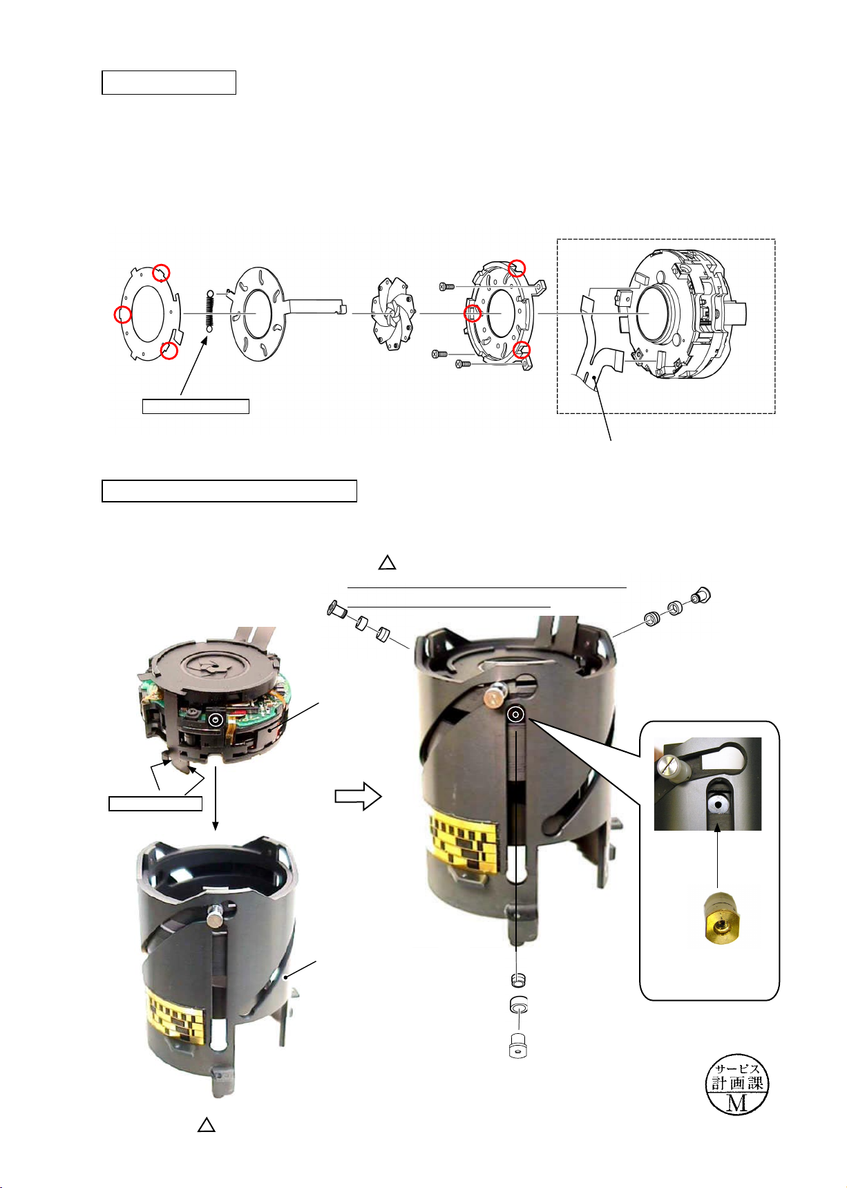
Removal of VR unit
INC
Take out three screws (#68).
①
(Addition)
Caution) The smaller diameter side of the stepped
rollers (#148 X 3) comes to VR unit.
#68×3
#147×3
#148×3
VR unit
②
JAA79471-R.3678.A
Remove the VR unit.
Aperture blade unit
Retaining plate
Blade actuating plate
Fixed tube
VR unit
Blade mounting plate
Blade×7
Changed page
#63
× 1
#56×3
- D14 ・ AF-S VRDX18-200/3.5-5.6G -
VR FPC unit
March. 17. 2006

3rd-4th lens group cam ring
INC
Remove each roller.
Remove 3rd-4th lens-G cam ring.
#102
#103 AF
#82
JAA79471-R.3678.A
#102
#103AH
#82
#99
#94AD
#82
#82
#84AD
#83
#149
#102×3
#146
#150
Revision
3rd-4th lens-G cam ring
#111
Encoder FPC
Changed page
1 October. 20. 2006
- D15 ・ AF-S VRDX18-200/3.5-5.6G -

2. Assembly / Adjustment
INC
JAA79471-R.3678.A
Encoder FPC
Distance encoder
Reference position for attachment
Fixed tube
3rd-4th lens group cam ring
Apply to the overall surface of the inside.
Grease: MZ-800S
Zoom encoder
Reference position for attachment
To cam groove
Grease: I-40
Align the concave portion of the 3rd-4th lens-group cam ring with the cutout of the xed tube, and assemble
①
them.
Attach each roller that ts the grooves.
②
Attach each tape.
③
Revision
△(
Adhesive: Lockend BR
#102
)
#103
A-F
#82
#103 A-H
#82
#99
#94 A-D
#82
#82
#84 A-D
#83
Adhesive: Lockend R
Addition
△(
#102
Fixed tube
#111
)
Apply to the sliding surface with Fixed tube
Grease: MZ-800S
#146×3
Cutout
Concave portion
3rd-4th lens-G cam ring
Addition
△(
Cam groove× 6 places
Grease: GP-1RS
Addition
△(
)
)
Changed page
#149
#146×3
△(
5 October.20.2006
△×
#150
Addition
)
#149
- A1 ・ AF-S VRDX18-200/3.5-5.6G -
#111
#150
JAA79471-R.3678.A
INC
Aperture blade unit
Fit the three convex portions of the retaining plate into the three holes of the blade mounting plate in the order
・
of ① and ②.
VR unit
Retaining plate
①
②
①
Adhesive: Screwlock
Blade actuating plate
Blade×7
Installation of VR unit into Fixed tube
① Assemble the VR unit into the xed tube.
(Addition)
Caution) The smaller diameter side of the stepped
rollers (#148 X 3) comes to VR unit.
Blade mounting plate
Insert the three nuts (#68) at the position
②
shown in Fig.1.
VR FPC unit
#68×3
#147×3
#148×3
Grease: MZ-800S
VR unit
Fixed tube
Fig.1
Changed page
× 1
- A2・ AF-S VRDX18-200/3.5-5.6G -
March.17.2006
4th lens group sliding ring
INC
Assemble the 4th lens-group sliding ring into
・
the xed tube.
Fix them with three screws (#81).
・
JAA79471-R.3678.A
Screw holes for 4th lens-G×3
4th lens-G sliding ring
Adhesive: Lockend R
#81×3
#84×3
Installation of VR FPC unit
Reference plane for attaching VR FPC
Pull out the VR FPC from the
hole.
#150
#149
VR FPC
Position for attaching VR
FPC unit.
VR FPC
Caution: Attach the FPC
without any slacks.
- A3・ AF-S VRDX18-200/3.5-5.6G -
JAA79471-R.3678.A
- A4・ AF-S VRDX18-200/3.5-5.6G -
・
Attach the brush by turning the convex portion all the way to the direction of the arrow so that the brush is
positioned as shown in "Fig.1".
#67×3
Adhesive: Lockend B
Aligned position of Zoom brush
Fig.1
#109×2
#106
Zoom brush
Convex portion
・
Assemble the xed tube into the 2nd lens-group straight ring unit, and x them with three screws (#67).
Fixed tube
Adhesive: Screwlock
2nd lens-group straight ring unit
2nd lens-G straight ring unit
Zoom brush
INC
JAA79471-R.3678.A
INC
Cover ring unit
Assemble the reinforcing ring unit and the cover ring unit, and x them with three screws (#110).
・
Reinforcing ring
unit
Cover ring unit
#110×3
Adhesive: Lockend B
When the three screws (#110) are attached,
・
the vertical position of the screw slot is
considered as 90°-direction. Then, if the
screw stops where the slot is at an angle
exceeding 45°, or in a horizontal position
(See "NG"), put the washer (#107) and
tighten the screw again.
(Addition)
△
Caution: In case of "NG", the screw slot
touches and scrapes against the
inner groove of the cover ring
unit. The may cause a dirt or
malfunction. (ref. Fig.1)
45°
GOOD
90°
45°
NG
#107
#110
Fig.1
Changed page
× 1
- A5・ AF-S VRDX18-200/3.5-5.6G -
March.17.2006
Zoom index ring
INC
Put the two screws (#112) into the block (#155).
①
JAA79471-R.3678.A
Block
Zoom index ring
#112×2
Adhesive: Screwlock
② Align the edge of "∞" of the distance scale sticker with the index of the zoom index ring, and assemble the
gear unit. Then, turn the gear unit clockwise and align the "∞" mark with the index. (Fig1)
③ Align the cutout of the zoom index ring with the convex portion of the zoom ring, and assemble them.
(Fig2)
④ Fix the zoom control key with the screw (#144).
⑤ Attach the name plate and window (#76).
Name plate
Zoom ring
#83
#84A-D
#82
Zoom control key
Adhesive: Lockend R
Apply to
the hole.
#144
Apply to the overall contacting
surface with Zoom index ring.
Grease: MZ-800S
Grease: MZ-800S
Apply to the sliding surface at 3
locations with the shoulder screw
(#110) of the previous page.
Edge of "∞"
Gear unit
Apply to the entire circumferential
jointing surface.
Gear unit
Zoom index ring
Cutout
Grease: MZ-800S
#76
Convex portion
Fig
2
Fig1
- A6・ AF-S VRDX18-200/3.5-5.6G -
Zoom index ring
Cutout
Fig
2
GMR sensor FPC unit
INC
① Pass the FPC of the GMR sensor FPC unit
through the hole to assemble.
GMR sensor
FPC unit
Attach the retaining plate (#97) and the plate spring
②
(#130), then x them with two screws (#112).
Zoom index ring
JAA79471-R.3678.A
#97
#130
Caution:
When the GMR sensor FPC unit is mounted, do NOT bend the
area of doted lines.
#112×2
Installation of Zoom index ring unit in Lens body
① Align the vertical groove of the zoom index ring unit with the pin "A" of the lens body, and assemble them.
Set the zoom ring to the wide-position, while the distance index to "close"-side.
②
Tighten the two screws
③
#123).
(
Adhesive: Screwlock
#123×2
Zoom index ring unit
Distance index
Vertical groove
Lens body
Attach the polyester tape.
④
Pin A
Polyester tape
- A7・ AF-S VRDX18-200/3.5-5.6G -
Position for at
taching tape
Clearance:
approx.1
-
JAA79471-R.3678.A
INC
4th lens group
Moved to page A16-1
△(
)
・ Fit the two cutouts and three screw holes of the washer (#139) in the 4th lens-group sliding frame.
Fit the two cutouts and three screw holes of the 4th lens group in the 4th lens-group sliding frame, then x
・
them with three screws (#124).
#124×3
4th lens group
#139A~H
MF ring
・ Assemble the MF-ring into the
zoom ring.
Apply to the overall sliding surface.
Grease: MZ-800S
MF ring
Changed page
△×
1
- A8 ・ AF-S VRDX18-200/3.5-5.6G -
October.20.2006
SWM unit
INC
SWM unit
JAA79471-R.3678.A
Adhesive: Screwlock
#145×2
Caution:
Do NOT touch the A-part directly by
hand.
A-part
Focus key
① Set the MF ring to "close"-side, while the zoom ring to "wide"-side.
② Rotate #25 (See "Pic.1") by hand so that the groove of #25 is set at the position of "Pic. 2".
③ Put the focus key and the plate spring (#157) in the groove of #25, and x them with the screw (#122).
Attach the screw (#122) by
*
MF ring
Zoom ring
#25
Pic. 1
Groove
positioning #157 outwards.
#122
Adhesive:Screwlock
#157
Edge
Focus key
#25
Focus key screw hole
- A9・ AF-S VRDX18-200/3.5-5.6G -
Pic. 2

JAA79471-R.3678.A
INC
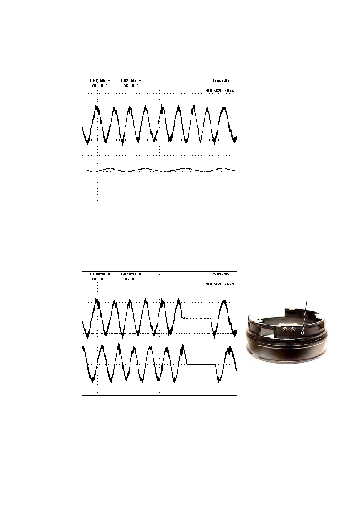
Inspection and adjustment of output waveform of MR encoder
● When the MR head is disassembled and replaced, be sure to make an adjustment.
1. Device:
・
・
・
Caution:
Single-output rated voltage power-supply
Oscilloscope
Self-made tool 1 unit
1 unit
1 unit: 5V 100mA
If there is a problem with continuity between the contacts of the self-made tool and the relay FPC,
the contacting surface of the relay FPC may be dirty, eroded, or oxidized. So polish the contacts and
connect them.
2. Preparation of the lens for measurement
・
Assemble the MR-head-attached zoom index ring unit, the SWM, and the MF ring into the lens body.
Then connect the assembled lens to each measuring machines as follows:
Attachment diagram
・
【
】
PCB (Front)
Rated voltage power-supply
PCB (Back)
To back
side
Oscilloscope
Oscilloscope
Rated voltage power-supply
Rated voltage power-supply
Caution:
The connector of the back of
the PCB is not used.
How to inspect and adjust:
・
Conrm that the electric current and voltage of the connected rated voltage power-supply are set values, then
①
turn it ON.
Set the oscilloscope, and turn the MR ring.
②
(2ch)
(1ch)
(+)
(-)
Self-made tool
(GND)
(+)
Set value
5.0 V
100 mA
Oscilloscope
(2ch type)
Note: The waveform varies according to the rotational speed of the focus ring. So change "Time/Div” setting
accordingly.
- A10 ・ AF-S VRDX18-200/3.5-5.6G -
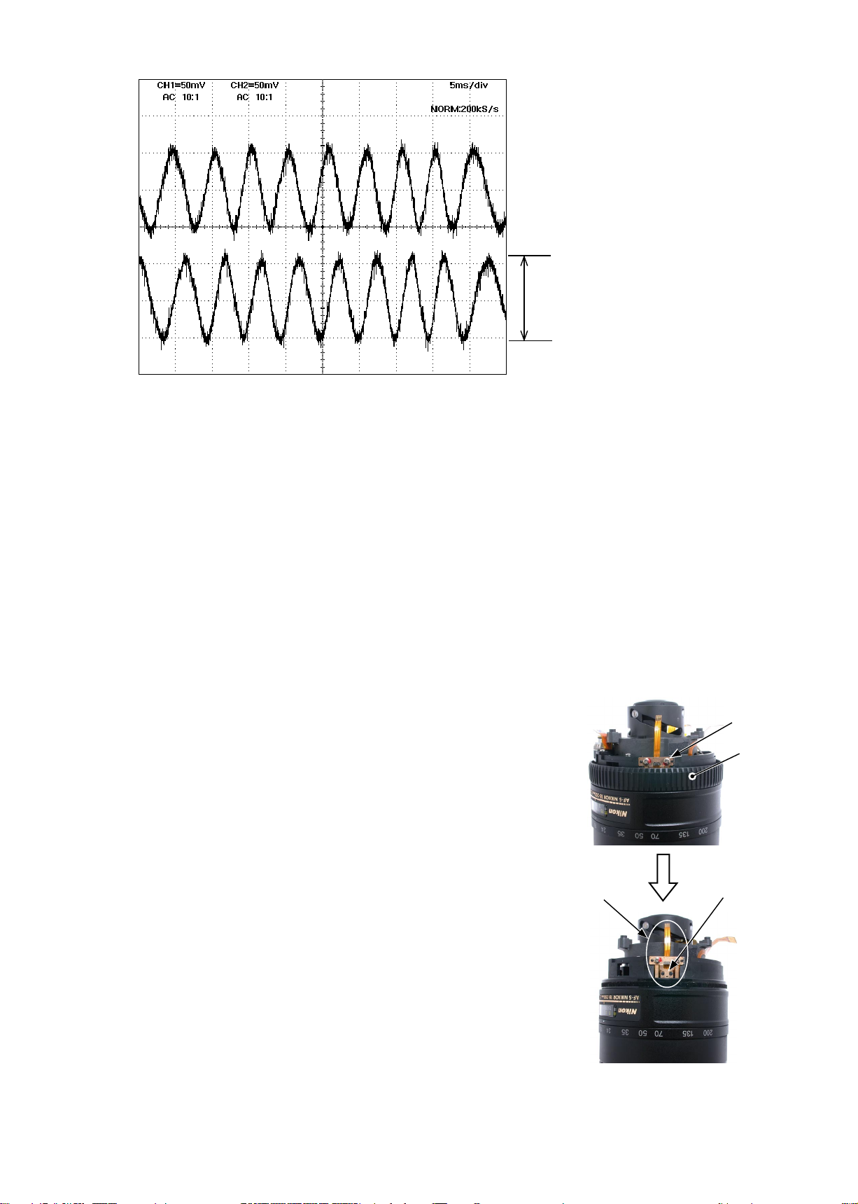
CH1
INC
JAA79471-R.3678.A
● Oscilloscope setting
V/Div (ch1) : 50 mV
V/Div (ch2) : 50 mV
Coupling : AC
Time/Div : 5 m Sec
Trigger Mode : NORMAL
Trigger Coupling : AC
CH2
Fig.1
In case large waveform-noise (as shown in Fig. 1) is detected, use the FILTER function.
③
How to set FILTER function (e.g. DL1540 manufactured by YOKOGAWA
1. Press the FILTER button.
2. Select “Smooth” of the menu on screen and turn it ON.
Amplitude
Standard:
Note:
Amplitude of all pulses/
waveforms is 80mV or more.
Check the waveform by moving the
focus ring back and forth from the
innity-end to the close-end positions
entirely.
)
④
In case the amplitude is small, disassemble up to
the stage of the GMR sensor FPC unit. Then if the
deformation is detected in the MR head, correct the
deform of the MR head. On the other hand, if such
correction is impossible or no deformation is detected,
replace the GMR sensor FPC unit. (Fig.2)
Note: When adjustments are made, prevent the
magnetic surface and MR head from touching the
magnetized driver bit. Otherwise, the magnetic
data may be damaged.
GMR sensor FPC unit
#123×2
MF ring
MR head
Fig.2
- A11 ・ AF-S VRDX18-200/3.5-5.6G -
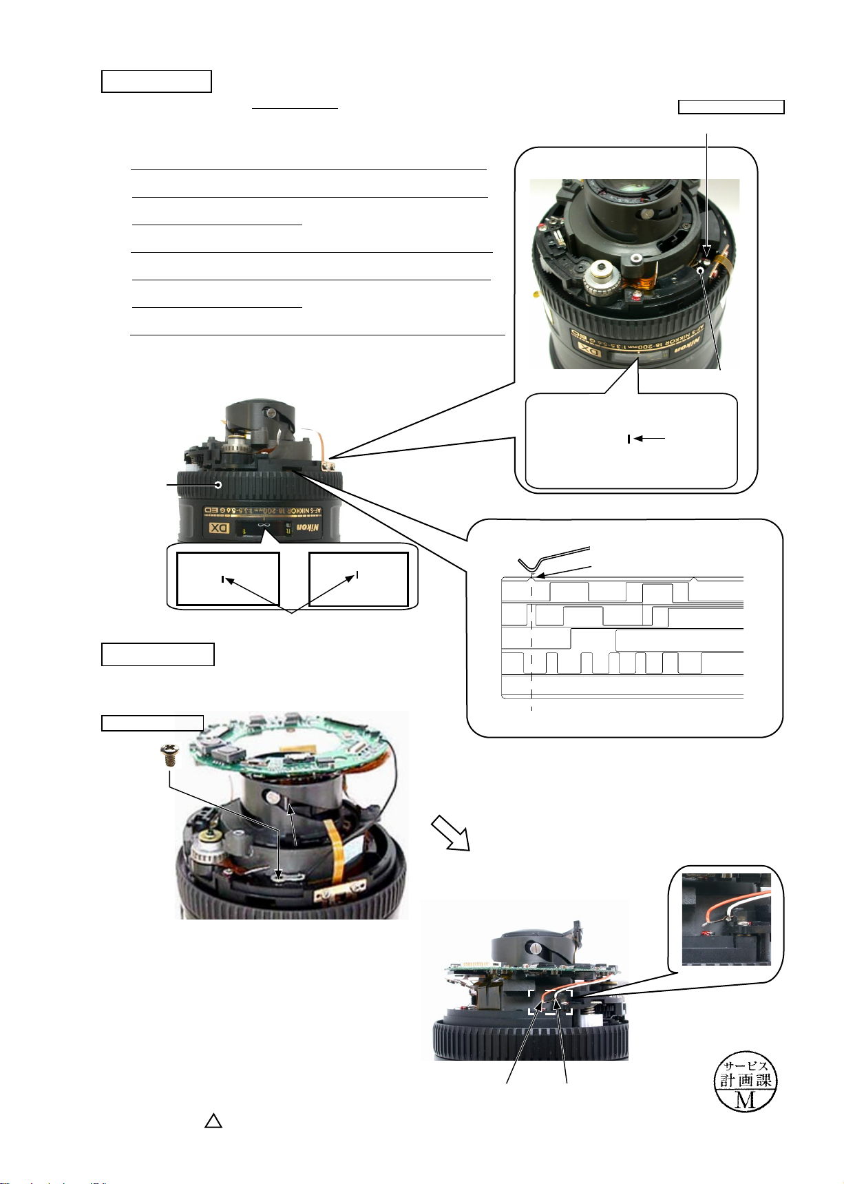
Ref.
INC
<
● As shown in Fig. 1,
>
JAA79471-R.3678.A
if the amplitude of only either CH1 or CH2 is small, one of the 2 screws (#218) may be
loosened, so check for it. If this is not the case, the MR head may malfunction, so replace the
FPC
unit and make a readjustment.
CH1
CH2
Fig.1
GMR sensor
As shown in Fig. 2,
●
magnetic data of the tape may be damaged. So replace the main xed tube unit and make a readjustment.
Replacing only the magnetic surface is impossible.
CH1
CH2
if the amplitude partially drops between the innity and the close-distance, the
Zoom index ring
⑤
Turn off the rated voltage power-supply.
Fig.2
- A12 ・ AF-S VRDX18-200/3.5-5.6G -
Distance-brush
INC
(Revision)
△
and set the distance scale to "1 m".
① Rotate the MF-ring to "close"-end.
② Attach the distance-brush with the screw (#112) temporarily.
(Revision)
△
③ Rotate the MF-ring and set the distance scale to the center
of "∞". Check if the ditance-brush comes to the reference
position or not. (ref. Fig.1)
④ If not, loose the screw (#112) and adjust the position. (The
screw (#112) cannot be seen, so rotate the MF-ring and set
the distance scale to "3 m".)
⑤ After the adjustment, x the screw (#112) with the screwlock.
(Revision)
△
JAA79471-R.3678.A
Adhesive: Screwlock
#112
Distance-brush
(Revision)
△
MF ring
Position for
③
∞
Distance scale
(Reference line)
Main PCB unit
Fix the lug plate with the screw (#123).
①
Adhesive: Screwlock
#123
Position
3
④
Position for
1
(Revision)
△
Position for Distance-brush
Reference position
Fig.1
①
Distance
scale
(Reference
line)
Changed page
× 5
Lug plate
Solder the two wires on the SWM unit.
②
Orange
White
- A13 ・ AF-S VRDX18-200/3.5-5.6G -
March.17.2006
 Loading...