

Page 1

BSM- 9510J
BSM- 9510K
MU- 950RJ
MU- 950RK
RY- 002PA
AY- 900PA
AY- 910PA
AA- 900PA
WS- 920PA
EK- 900P
Life Scope M
BEDSIDE MONITOR
BSM-9510
0634-001352
Page 2

CONTENTS
Contents
Conventions Used in this Manual and Instrument ....................................................................i
Warnings, Cautions and Notes .......................................................................................i
Explanations of the Symbols in this Manual and Instrument.........................................ii
Section 1 General.................................................................................. 1C.1
Introduction ..........................................................................................................................1.1
General Information on Servicing .........................................................................................1. 2
Service Policy, Service Parts and Patient Safety Checks....................................................1.4
Service Policy ............................................................................................................1.4
Service Parts .............................................................................................................1. 4
Patient Safety Checks ...............................................................................................1.5
Composition .........................................................................................................................1.6
Bedside Monitor Main Unit .........................................................................................1.6
Specifications ......................................................................................................................1.7
Bedside Monitor Main Unit, MU-950RJ/RK.................................................................1.7
Sound.........................................................................................................................1.7
Alarm .........................................................................................................................1.7
Display ....................................................................................................................... 1.7
Module Slots ..............................................................................................................1.7
Multi Parameter Module , AY -900PA ............................................................................1.8
ECG.................................................................................................................1.8
Respiration (Transthoracic impedance pneumography).....................................1.9
SpO2 and Pulse W a ve (Arterial Pleth ysmographic Wavef orm)..........................1.9
Non-invasive Blood Pressure, NIBP ..............................................................1.10
Multi Amplifiers ........................................................................................................1.10
Invasive Blood Pressure, IBP........................................................................1.10
Temperature ...................................................................................................1.11
Cardiac Output, CO........................................................................................ 1.11
Respiration (Thermistor probe pneumography) ...............................................1.12
Inspired Oxygen Fractional Concentration, FiO
Expired Carbon Dioxide Tension, CO
ECG/BP Output .......................................................................................................1.13
Multi Parameter Module , AY -910PA ..........................................................................1.13
SpO2 and Pulse W a ve (Arterial Pleth ysmographic Wavef orm)........................1.13
Recorder Module, WS-920PA ...................................................................................1.14
Po wer Requirement ..................................................................................................1.14
Environment for All Units and Modules ....................................................................1.14
Dimensions and W eight (Appro ximate).....................................................................1.14
Electromagnetic Compatibility..................................................................................1.15
Safety Standard .......................................................................................................1.15
Panel Description ...............................................................................................................1.16
Control Panel............................................................................................................1.16
Remote Control ........................................................................................................1.17
..........................................................................................................
2
...............................................................................
2
1.12
1.12
Service Manual BSM-9510 C.1
Page 3

CONTENTS
Main Unit..................................................................................................................1.18
Multi Par ameter Module............................................................................................1.21
Smart Module ..........................................................................................................1.23
Recorder Module ......................................................................................................1.24
Connection Diagram ...........................................................................................................1.25
Block Diagram....................................................................................................................1.26
Section 2 Troubleshooting................................................................... 2C.1
T roubleshooting Table ...........................................................................................................2.1
How to Use the Troubleshooting Table ..............................................................2.1
Po wer-Related Problem ..............................................................................................2.2
Display Problems .......................................................................................................2.2
Sound Problem ..........................................................................................................2.2
Ke y Operation Prob lem s.............................................................................................2.3
Recorder Problem ......................................................................................................2.3
Other Module-Related Problem ..................................................................................2.3
Section 3 Diagnostic Check ................................................................. 3C.1
Introduction ..........................................................................................................................3.1
Po wer On Self Chec k ...........................................................................................................3.2
Calling up the Diagnostic Check and System Setup Screen ................................................3.3
MU Manual Check................................................................................................................3.5
Memory Check...........................................................................................................3.5
Flash ROM (program) Check ...........................................................................3.6
Flash ROM (data) Check..................................................................................3.6
SRAM Check ...................................................................................................3.6
DRAM Check ...................................................................................................3.7
Com Check ................................................................................................................3.7
Network I/F Check ...........................................................................................3.8
Serial I/F Check .............................................................................................3.10
JA I/F Check..................................................................................................3.10
Display Check..........................................................................................................3.1 3
Frame Mem Chec k.........................................................................................3.13
Graphic Check ...............................................................................................3.1 4
Wav ef orm Chec k............................................................................................3.14
Backlight Check.............................................................................................3.14
Key LED Chec k........................................................................................................3.15
Key Check .....................................................................................................3.15
Remote Check ...............................................................................................3.1 6
Alarm Indicator Check.................................................................................... 3.16
Alarm Pole Check ..........................................................................................3.1 7
Other Check.............................................................................................................3.1 7
Sound Check .................................................................................................3.18
Po wer Chec k.................................................................................................. 3.18
Card I/F Check............................................................................................... 3.18
Timer IC Check ..............................................................................................3.19
C.2 Service Manual BSM-9510
Page 4

CONTENTS
Section 4 Board/Unit Description........................................................ 4C.1
Signal Flow ..........................................................................................................................4.1
Vital Sign Signals from Patients.................................................................................4.1
Display Data ..............................................................................................................4.1
Pow er Control Signal b y Front Pow er Switch or Power Button on
Optional Remote Control .......................................................................................4.1
MAIN Board UR-3485 ...........................................................................................................4.2
EXT JA Board UR-3489 .......................................................................................................4.2
JA Motherboard UR-3486 .....................................................................................................4.2
IR DETECT Board UR-3487 .................................................................................................4.3
LCD JUNC Board UR-3504 ...................................................................................................4.3
LED Board UR-3393 .............................................................................................................4.3
OPERA TION Board UR-3506................................................................................................4.3
P ower Supply Unit SC-036R.................................................................................................4.4
Section 5 Disassembly and Assembly............................................... 5C.1
Before Y ou Begin..................................................................................................................5.1
Warnings and Cautions...............................................................................................5.1
Required T ools............................................................................................................5.1
Replacing MAIN Board .........................................................................................................5.2
Replacing Fuse ....................................................................................................................5.5
Replacing Po wer Supply Unit ...............................................................................................5.7
Replacing JA Motherboard .................................................................................................5.10
Replacing IR DETECT Board .............................................................................................5.13
Replacing LCD Unit ............................................................................................................5.16
Replacing DC-AC In verter ..................................................................................................5.19
Replacing Backlight Lamps................................................................................................5.22
Replacing LCD Filter...........................................................................................................5.26
Replacing OPERATION Board............................................................................................5.29
Replacing Lithium Battery ..................................................................................................5.32
Section 6 Maintenance ......................................................................... 6C.1
Maintenance Check Items....................................................................................................6.1
External......................................................................................................................6.1
Safety ........................................................................................................................6.2
Modules .....................................................................................................................6.2
Display ....................................................................................................................... 6.3
Measuring Parameters ...............................................................................................6.3
Recorder.....................................................................................................................6.3
Backup.......................................................................................................................6.3
Others ........................................................................................................................6.4
Section 7 Adjustment ............................................................................ 7C.1
Service Manual BSM-9510 C.3
Page 5

CONTENTS
Section 8 Replaceable Parts List......................................................... 8C.1
Main Unit Parts ....................................................................................................................8.1
Section 9 Connector Pin Assignment ................................................ 9C.1
Input/Output Connector Pin Assignment ..............................................................................9.1
Alarm Output Socket, ALARM .........................................................................9.1
General Serial Socket, SERIAL .......................................................................9.1
Network Socket, NETWORK............................................................................9.2
JA Output Socket ............................................................................................9.2
Connector on MAIN Board ...............................................................................9.2
Connector on EXT JA Board............................................................................9.3
Memory Card Connector ..................................................................................9.3
OPERA TION Connector ...................................................................................9.4
LED Connector.................................................................................................9.4
LCD Connector.................................................................................................9.5
JA Motherboard Connector...............................................................................9.5
Connectors on the Pow er Supply Unit..............................................................9.6
BDM Connector................................................................................................9.6
DEBUG Connector ...........................................................................................9.7
C.4 Service Manual BSM-9510
Page 6

Conventions Used in this Manual and Instrument
Warnings, Cautions and Notes
Warnings, cautions and notes are used in this manual to alert or signal the reader to specific information.
WARNING
A warning alerts the user to possible injury or death associated with the use or misuse of the instrument.
CA UTION
A caution alerts the user to possible injury or problems with the instrument associated with its use or
misuse such as instrument malfunction, instrument failure, damage to the instrument, or damage to other
property.
NOTE
A note provides specific information, in the form of recommendations, prerequirements, alternative
methods or supplemental information.
Service Manual BSM-9510 i
Page 7
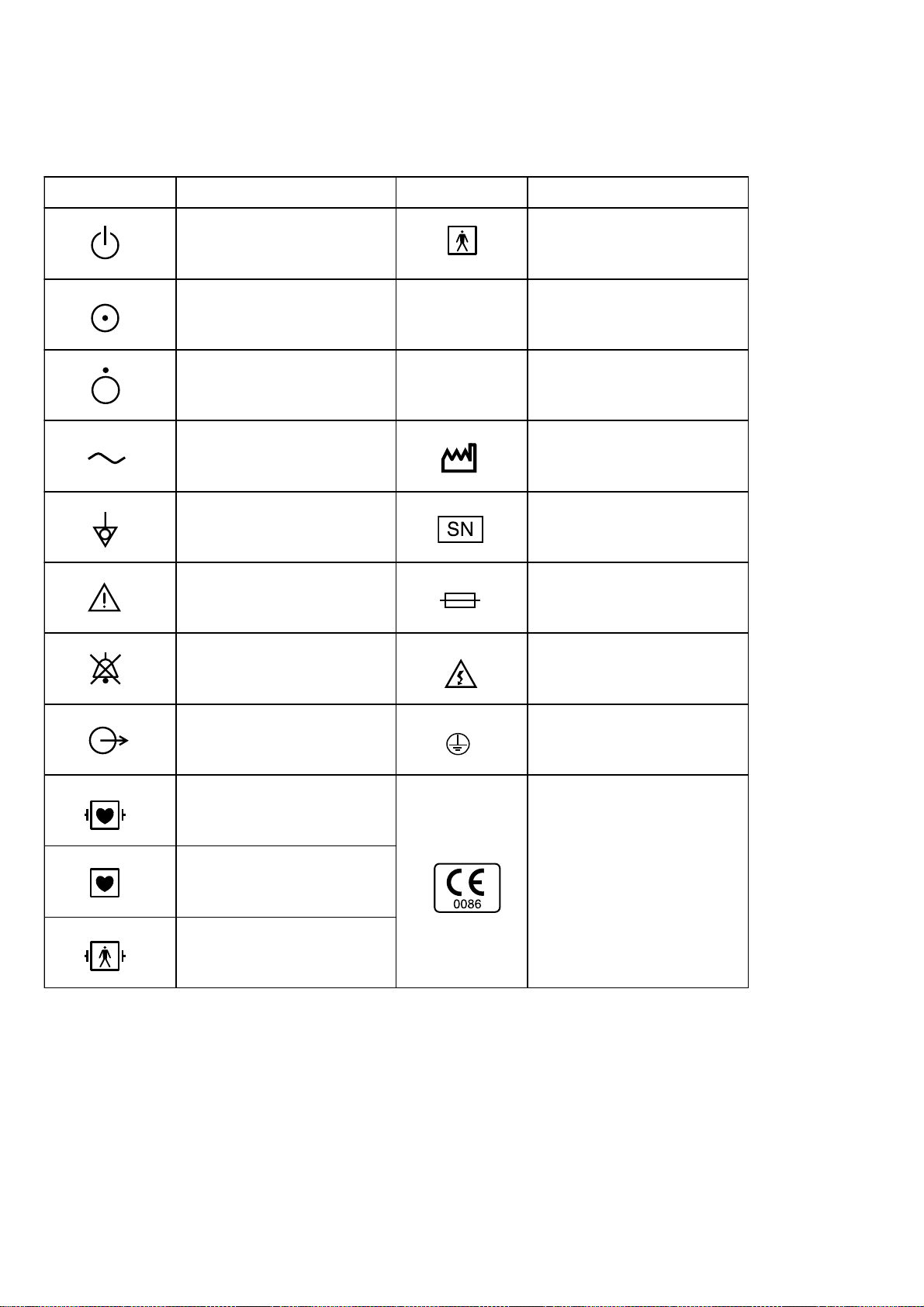
Explanations of the Symbols in this Manual and Instrument
The following symbols found in this manual/instrument bear the respective descriptions as given.
On panels
Symbol Description Symbol Description
Standby lamp
“On” only for a part of
equipment
“Off” only for a part of
equipment
Alternating current
Equipotential terminal
Attention, consult operator’s
manual
Alarm off/suspend
IPX4
IPX7
Type BF applied part
Splash-proof equipment
Watertight equipment
Year of manufacture
Serial number
Fuse
High voltage
Output terminal
Defibrillation-proof
type CF applied part
Type CF applied part
Defibrillation-proof
type BF applied part
Protective earth
The CE mark is a protected
conformity mark of the
European Community. The
products herewith comply with
the requirements of the Medical
Device Directive 93/42/EEC.
ii Service Manual BSM-9510
Page 8
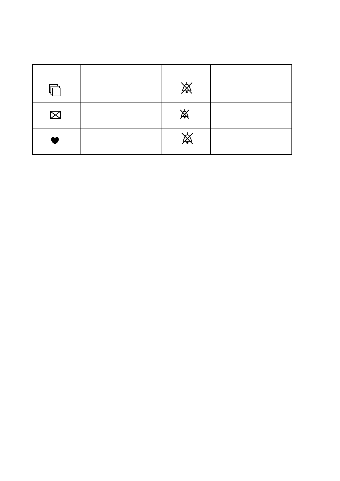
On screen
2
Symbol Description Symbol Description
Open pulldown menu
Close window button
QRS sync mark
Alarm off/suspend
Alarm off/suspend with
remaining time
Arrhythmia analysis off
ARR
Service Manual BSM-9510 iii
Page 9

Section 1 General
Introduction .........................................................................................................................1.1
General Information on Servicing ........................................................................................1.2
Service Policy, Service Parts and Patient Safety Checks...................................................1.4
Service Policy ...........................................................................................................1.4
Service Parts ............................................................................................................1.4
Patient Safety Checks ..............................................................................................1.5
Composition ........................................................................................................................1.6
Bedside Monitor Main Unit ........................................................................................1. 6
Specifications .....................................................................................................................1.7
Bedside Monitor Main Unit, MU-950RJ/RK................................................................1.7
Sound........................................................................................................................1.7
Alarm ........................................................................................................................1.7
Display ......................................................................................................................1.7
Module Slots .............................................................................................................1.7
Multi Parameter Module , AY -900PA ...........................................................................1.8
ECG................................................................................................................1.8
Respiration (Transthoracic impedance pneumography)....................................1.9
SpO2 and Pulse W a ve (Arterial Pleth ysmographic Wavef orm).........................1.9
Non-invasive Blood Pressure, NIBP .............................................................1.10
Multi Amplifiers .......................................................................................................1.10
Invasive Blood Pressure, IBP.......................................................................1.10
Temperature ..................................................................................................1.11
Cardiac Output, CO.......................................................................................1.11
Respiration (Thermistor probe pneumography) ..............................................1.12
Inspired Oxygen Fractional Concentration, FiO
Expired Carbon Dioxide Tension, CO
ECG/BP Output ......................................................................................................1.13
Multi Parameter Module , AY -910PA .........................................................................1.13
SpO2 and Pulse W a ve (Arterial Pleth ysmographic Wavef orm).......................1.13
Recorder Module, WS-920PA ..................................................................................1.14
Po wer Requirement .................................................................................................1.14
Environment for All Units and Modules ...................................................................1.1 4
Dimensions and W eight (Appro ximate)....................................................................1.14
Electromagnetic Compatibility.................................................................................1.15
........................................................................................................
2
.............................................................................
2
1.12
1.12
Service Manual BSM-9510 1C.1
Page 10

Safety Standard ......................................................................................................1.15
Panel Description .............................................................................................................. 1.16
Control Panel........................................................................................................... 1.16
Remote Control .......................................................................................................1.17
Main Unit.................................................................................................................1.18
Multi Par ameter Module...........................................................................................1.2 1
Smart Module .........................................................................................................1.23
Recorder Module .....................................................................................................1.24
Connection Diagram ..........................................................................................................1.25
Block Diagram...................................................................................................................1.26
1C.2 Service Manual BSM-9510
Page 11

Introduction
1. GENERAL
This service manual provides useful information to qualified personnel to
understand, troubleshoot, service, maintain and repair the BSM-9510J/K Bedside
Monitor (referred to as “the instrument” in this service manual).
All replaceable parts or units of this instrument are clearly listed with
exploded illustration to help you locate the parts quickly.
The “Maintenance” section in this service manual describes the maintenance
that should be performed by qualified service personnel. The “Maintenance”
section in the operator’s manual describes the maintenance that can be
performed by the user.
The information in the operator’s manual is primarily for the user. However, it
is important for service personnel to thoroughly read the operator’s manual
and service manual before starting to troubleshoot, service, maintain or repair
this instrument. This is because service personnel need to understand the
operation of the instrument in order to effectively use the information in the
service manual.
Service Manual BSM-9510 1.1
Page 12

1. GENERAL
General Information on Servicing
Note the following information when servicing the instrument.
Safety
••
• There is the possibility that the outside surface of the instrument,
••
such as the operation keys, could be contaminated by contagious
germs, so disinfect and clean the instrument before ser vicing it. When
servicing the instrument, wear rubber gloves to protect yourself from
infection.
••
• There is the possibility that when the lithium battery is broken, a
••
solvent inside the lithium battery could flow out or a toxic substance
inside it could come out. If the solvent or toxic substance touches your
skin or gets into your eye or mouth, immediately wash it with a lot of
water and see a physician.
CAUTIONS
Liquid ingress
The instrument is not drip-proof, so do not install the instrument
where water or liquid can get into or fall on the instrument. If liquid
accidentally gets into the instrument or the instrument accidentally
drops into liquid, disassemble the instrument, clean it with clean water
and dry it completely. After reassembling, verify that there is nothing
wrong with the patient safety checks and function/performance checks.
If there is something wrong with the instrument, contact your Nihon
Kohden representative to repair .
Environmental Safeguar ds
Depending on the local laws in your community, it may be illegal
to dispose of the lithium battery and CRT unit in the regular waste
collection. Check with your local officials for proper disposal
procedures.
Disinfection and cleaning
T o disinfect the outside surface of the instrument, wipe it with a
non-abrasive cloth moistened with any of the disinfectants listed below .
Do not use any other disinfectants or ultraviolet rays to disinfect the
instrument.
- Chlorohexidine gluconate solution: 0.5%
- Benzethonium chloride solution: 0.2%
- Glutaraldehyde solution: 2.0%
- Benzalkonium chloride: 0.2%
- Hydrochloric alkyl diaminoethylglycine: 0.5%
1.2 Service Manual BSM-9510
Page 13

1. GENERAL
Transport
••
• Use the specified shipment container and packing material to
••
transport the instrument. If necessary, double pack the instrument.
Also, put the instrument into the shipment container after packing so
that the buffer material does not get into the inside of the instrument.
••
• When transporting the board or unit of the instrument, be sure to use
••
a conductive bag. Never use an aluminum bag when transporting the
power board, power unit or board on which a lithium battery is
mounted. Also, never use a styrene foam or plastic bag which
generates static electricity to wrap the board or unit of the instrument.
Handling the instrument
••
• Because the outside surface of the instrument is made of resin, the
••
outside surface of the instrument is easily damaged. So when handling
the instrument, remove clutter from around the instrument and be
careful to not damage the instrument or get it dirty .
••
• Because most of the boards in the instrument are multilayer boards
••
with surface mounted electrical devices (SMD), when removing and
soldering the electrical devices, a special tool is required. To avoid
damaging other electrical components, do not remove and solder SMD
components yourself.
Measuring and Test Equipment
Maintain the accuracy of the measuring and test equipment by
checking and calibrating it according to the check and calibration
procedures.
Service Manual BSM-9510 1.3
Page 14

1. GENERAL
Service Policy, Service Pa rts and Patient Safety Checks
Service Policy Our technical service policy for this instrument is to replace the faulty unit, board
or part or damaged mechanical part with a new one. Do not perform electrical
device or component level repair of the multilayer board or unit. We do not
support component level repair outside the factory for the following reasons:
• Most of the boards are multilayer boards with surface mounted electrical
devices, so the mounting density of the board is too high.
• A special tool or high degree of repair skill is required to repair the multilayer
boards with surface mounted electrical devices.
Disassemble the instrument or replace a board or unit in an environment where the
instrument is protected against static electricity.
As background knowledge for repair, pay special attention to the following:
• You can reduce the repair time by considering the problem before starting repair.
• You can cla rify the source of most of the troubles using the information from the
diagnostic check function of the instrument. Refer to “Diagnostic Check “ of
this manual.
Service Parts
Refer to “Replaceable Parts List” of this manual for the service parts for technical
service that we provide.
NOTE
When ordering parts or accessories from your Nihon Kohden
representative, please quote the NK code number and part name which
is listed in this service manual, and the name or model of the unit in
which the required part is located. This will help us to promptl y attend
to your needs. Always use parts and accessories recommended or
supplied by Nihon Kohden Corporation to assure maximum
performance from your instrument.
1.4 Service Manual BSM-9510
Page 15

1. GENERAL
Patient Safety Checks Periodic maintenance procedures and diagnostic check procedures are
provided in this manual to ensure that the instrument is operating in
accordance with its design and production specifications. To verify that the
instrument is working in a safe manner with regard to patient safety, patient
safety checks should be performed on the instrument before it is first installed,
periodically after installation, and after any repair is made on the instrument.
For patient safety checks, perform the following checks as described in the
International Electrotechnical Commission’s standard, IEC60601-1 (1988):
• Protective earth resistance check
• Earth leakage current check
• Enclosure leakage current check
• Patient leakage current check
• Withstanding voltage check
Service Manual BSM-9510 1.5
Page 16
1. GENERAL
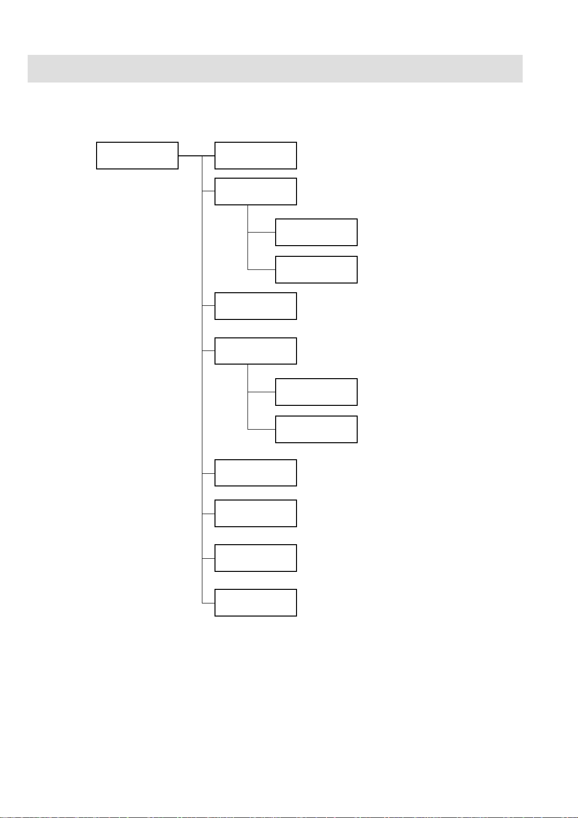
Composition
Bedside Monitor Main Unit
MU-950RJ/RK
Main unit
CD-219P
UR-3510
UR-3486
UR-3511
Chassis Unit
MAIN & EXT JA Board
UR-3485 MAIN Board
UR-3489
JA Motherboard
IR DETECT & LCD JUNC Board
UR-3487
UR-3504
EXT JA Board
IR DETECT Board
LCD JUNC Board
UR-3393
UR-3506
SC-036R
YS-022R4
YS-022R5
LED Board
OPERA TION Board
Power Supply Unit
MU-950RJ Panel
MU-950RK Panel
1.6 Service Manual BSM-9510
Page 17

Specifications
Bedside Monitor Main Unit, MU-950RJ/RK
For other details, refer to the specifications of the respective module and unit.
Sound
Sound type: Alarm, synchronization, click
Alarm sound: Volume variable
Synchronization sound: Volume variable, pitch variable for SpO2 or BP
Click sound: Volume variable
Alarm
Alarm items: Upper/lower limits alarm, apnea alarm, arrhythmia alarm, module alarm,
external instrument alarm, electrode check alarm, faulty instrument alarm,
connector disconnection alarm, operating environment alarm
Alarm types: Crisis (red, blinking), Warning (yellow, blinking), Advisory (yellow,
lighting), Message, System Guidance
Alarm indication: Alarm indicator, highlighted numerical display, numerical display color,
alarm sound, highlighted message for arrhythmia
Alarm suspend: Provided (For 1, 2, 3, 4, 5, 10 min)
Alarm silence: Provided (For 1, 2, 3, 4, 5, 10 min)
Alarm setting: Individual upper/lower limits setting for each parameter
1. GENERAL
Display
Module Slots
Sweep speed: Respiration wave (respiration, CO2): 6 or 25 mm/s
Others: 25 mm/s
Display waveforms: ECG, IBP, ICP, SpO2, Respiration wave, C O2 and other parameters
depending on the module and unit
Numerical data display: Heart rate, VPC rate, arrhythmia message, ST level, IBP (systolic,
diastolic, mean), NIBP (systolic, diastolic, mean), respiration rate, pulse
rate, temperature, SpO2, CO2, O2, and other parameters depending on the
module and unit.
Synchronization mark: Heart rate sync mark, pulse rate sync mark
Trendgraph display time: 30 min, 1, 2, 4, 6, 8, 12 or 24 h
Display size: 10.4 inch
Viewing area: 211 × 158 mm
Resolution: 640 × 480 dots
Max. No. of waveform traces: 6 traces
Sweep time: about 6 s (When sweep speed is 25 mm/s)
Waveform display mode: Moving mode
No. of slots: 6
Service Manual BSM-9510 1.7
Page 18

1. GENERAL
Multi Parameter Module, AY-900PA
ECG
• Electrode offset potential tolerance: ± 500 mV
• Input dynamic range: ±10 mV
• Internal noise: ≤ 20 µVp-p, referred to input
• Input impedance: ≥ 5 MΩ (at 10 Hz)
• Common Mode Rejection Ratio: ≥ 95 dB (with a 51 kΩ/47 nF imbalance)
• Input bias current: ≤ 100 nA
• Heart rate count
Calculation method: 8-beat moving average/Instantaneous beat-to-beat (consecutive 2
beats averaged) (Selectable)
Counting range: 15 to 300 beats/min
• Arrhythmia analysis
Analysis method: Multi-template matching method
No. of channels: 2 channels
VPC counting range: 0 to 99 beats/min
Arrhythmia analysis: ASYSTOLE, V FIB, Vf/VT, V T ACHY , VPC RUN, COUPLET , EARL Y
V, BIGEMINY, FREQ VPC, T ACH Y , BRAD Y, PROLONGED RR
• Arrhythmia recall
Number of recall files: 32
Storage time per file: 8 s
• ST level measurement
No. of measurement channels: 3-electrode: 1 ch
6-electrode: max. 8 ch
10-electrode: max. 12 ch
Measuring range: ±2.5 mV
• Pacemaker pulse rejection capability ANSI/AAMI EC 13-1992 compatible
• Defibrillation-proof: ECG input protected against 400 J discharge
• ESU interference filter: Provided
• AC hum f ilter: Provided
• Lead
3-electrode cable: I, II, III
6-electrode cable: I, II, III, aVR, aVL, aVF, Va, Vb (Va and Vb: any 2 leads from chest
leads)
10-electrode cable: I, II, III, aVR, aVL, aVF, V1 to V6
• ECG frequency range
Signal bandwidth: DC to 90 Hz
Display bandwidth: Filter Drift free
Off Off 0.3 to 70 Hz
On Off 0.3 to 20 Hz
Off On 1.0 to 70 Hz
On On 1.0 to 20 Hz
1.8 Service Manual BSM-9510
Page 19

• Waveform display
Display sensitivity: 10 mm/mV ±5% (at × 1 sensitivity)
Sensitivity control: ×1/4, ×1/2, ×1, ×2, ×4 or A UT O
Drift rejection filter: Available
Pacing spike display: Available
Auto positioning: Available
• Heart rate display update cycle: Every 3 s or when alarm is generated
• Alarm
Upper limit range: 20 to 300 beats/min in 5 beats/min steps, OFF
Lower limit range: OFF, 15 to 295 beats/min in 5 beats/min steps
Alarm items: T ACHY, BRADY
Respiration (T ransthoracic impedance pneumography)
• Measuring impedance range: ≥ 2 kΩ
• Internal noise: ≤ 0.1 Ω
• Excitor current: 30 ±10 µArms at 40 kHz
1. GENERAL
• Frequency response: 0.1 to 3 Hz (−3 dB)
• Respiration counter
Counting range: 0 to 150 breaths/min
Apnea setting range: 5 to 40 s (set on the main unit)
• Defibrillation proof: Respiration input protected against 400 J discharge
• Waveform display
Display sensitivity: 10 mm/Ω (at × 1 sensitivity)
Sensitivity control: ×1/4, ×1/2, ×1, ×2, ×4 or A UT O
• Respiration rate display update cycle: Every 3 s or when alarm is generated
• Alarm
Upper limit range: 2 to 150 breaths/min in 2 breaths/min steps, OFF
Lower limit range: OFF, 0 to 148 breaths/min in 2 breaths/min steps
Apnea time: 5 to 40 s in 5 s steps, OFF
SpO2 and Pulse W ave (Arterial Pleth ysmographic Wavef orm)
With Nihon Kohden probe
• Measuring range
SpO2: 1 to 100% SpO2 in 1% SpO2 steps
Pulse rate: 30 to 300 beats/min
• SpO
accuracy
2
• SpO
display
2
80 to 100% SpO2: ±2% SpO
50 to 79% SpO2: ±3% SpO
Pulse rate display update cycle: Every 3 s or when alarm is generated
Sync tone modulation: Changes in 20 steps at 81 to 100% SpO
2
2
2
• Alarm
Upper limit range: OFF , 51 to 100% SpO2 in 1% SpO2 steps
Lower limit range: OFF, 50 to 99% SpO2 in 1% SpO2 steps
Service Manual BSM-9510 1.9
Page 20

1. GENERAL
Non-invasive Blood Pressure, NIBP
• Measuring method: Oscillometric
• Cuff pressure display range: 0 to 300 mmHg (0 to 40 kPa)
• Accuracy
0 to 200 mmHg: ±3 mmHg
200 to 300 mmHg: ±4 mmHg
• Safety
Maximum pressurization value cuff inflation limiter: Adult 300 mmHg
Neonate 150 mmHg
Cuff inflation time limiter: Adult 150 s
Neonate 80 s
• Measurement mode: Manual (Single measurement)
Continuous (Successive repetition or at 1 min interval for 15 min
period)
Periodic (In OR mode at 2, 2.5, 5, 10, 15, 30 min interval)
(In ICU mode at 5, 10, 15, 30 min, 1, 2, 4, 8 h interval)
• NIBP data display update cycle: Updated every measurement
• Measurement end sound: Generated when measurement ends (Set on the System Setup screen)
• Alarm (Systolic, Diastolic, Mean)
Upper limit range: 22 to 250 mmHg in 2 mmHg steps, OFF
Lower limit range: OFF, 20 to 248 mmHg in 2 mmHg steps
Multi Amplifiers
Measuring parameters: IBP, Temp, CO, Resp (thermistor), FiO2, CO2 (main stream)
Input impedance: 1 MΩ
Inv asive Blood Pressure, IBP
• Measuring range: −50 to 300 mmHg
• Measuring accuracy ±1% (≥ 100 mmHg), ±1 mmHg (< 100 mmHg)
• Auto zero balancing range: ±200 mmHg
• Auto zero balancing accuracy: ±1 mmHg
• Pulse rate counting range: 30 to 300 beats/min
• Pulse rate counting accuracy: ±1 beat/min
• Noise: ≤ 0.25 mmHg
• Temperature zero drift: ±0.1 mmHg/°C
• Frequency response: DC to 10/20 Hz, set on the main unit (Digital filter processing by
software)
• Blood pressure display range: 0 to 300 mmHg
• Display update cycle: Every 3 s or when alarm is generated
• BP tone: Provided, systolic value 20 to 120 mmHg, changes in 20 steps every
5 mmHg
1.10 Service Manual BSM-9510
Page 21

• Alarm (Systolic, Diastolic, Mean)
Upper limit range: 2 to 300 mmHg in 2 mmHg steps, OFF
Lower limit range: OFF , 0 to 298 mmHg in 2 mmHg steps
Temperature
• Measuring range: 0 to 45°C (32 to 113°F)
• Measuring accuracy
Sensor: ±0.1°C
Module: ±0.1°C (25 to 45°C, 77 to 113°F)
±0.2°C (Other range)
• Noise: ≤ 0.014°C at 37°C (99°F)
• Temperature drift: ±0.005°C/°C
• Temperature display
Display range: 0 to 45°C (32 to 113°F)
Display update cycle: Every 3 s
• Alarm
1. GENERAL
Upper limit range: 0.1 to 45°C (33 to 113°F) in 0.1°C (0.5°F) steps, OFF
Lower limit range: OFF, 0 to 44.9°C (32 to 112°F) in 0.1°C (0.5°F) steps
Cardiac Output, CO
• Measuring method: Thermodilution method
• Measuring range
Injectate temperature (Ti): 0 to 27°C (32 to 81°F)
Blood temperature (Tb): 15 to 45°C (59 to 113°F)
Thermodilution curve (∆ Tb): 0 to 2.5°C (32 to 36.5°F)
Cardiac output (CO): 0.5 to 20 L/min
• Measuring accuracy (catheter sensor accuracy is not included)
Ti: ±0.1°C
Tb 25 to 45°C: ±0.1°C
Tb 15 to 25°C: ±0.2°C
CO: ±5%
• Noise
Ti: ≤ 0.025°C
Tb: ≤ 0.016°C at 37°C (99°F)
∆Tb: ≤ 0.005°C at 37°C (99°F)
• Temperature drift
Ti: ±0.005°C/°C
Tb: ±0.005°C/°C
• Frequency response (∆Tb): 0 to 3 Hz (Digital filter processing)
• Catheter size: 5F , 7F or 7.5F
• Injectate volume range: 3, 5, 10 cc
• Cardiac output display
CO value display update cycle: Every measurement
Thermodilution curve display time:45 s
Service Manual BSM-9510 1.11
Page 22

1. GENERAL
• Alarm limits
CO: None
Blood temperature: 15 to 45°C in 0.1°C steps, OFF
Respiration (Thermistor probe pneumography)
• Respiration rate counting range: 0 to 150 resp/min
Apnea, 5 to 40 s
• Accuracy: ±1 resp/min
• Temperature measuring range: 10 to 40°C (50 to 104°F)
• Maximum detection resistance range: 1 kΩ
• Recorder sensitivity: ∆100 Ω/400 digits ±10%
(400 digits is equivalent to 1 cm on paper at ×1 recorder sensitivity)
• Noise: ≤1.0 Ω (referred to input)
• Frequency response: 0.1 to 3 Hz (Digital filter processing)
• Waveform display
Display sensitivity: 10 mm/100 Ω (at ×1 sensitivity)
Sensitivity control: ×1/4, ×1/2, ×1, ×2, ×4 or A UT O
• Respiration rate display update cycle: Every 3 s or when alarm is generated
• Alarm
Upper limit range: 2 to 150 breaths/min in 2 breaths/min steps, OFF
Lower limit range: OFF, 0 to 148 breaths/min in 2 breaths/min steps
Apnea time: 5 to 40 s in 5 s steps, OFF
Inspired Oxygen Fractional Concentration, FiO
• Measuring range: 10 to 100% O
2
in 1% steps
2
• Amplifier accuracy : ±1% full scale
• Accuracy including sensor
21% O2 calibration: ±3% full scale
100% O2 calibration: ±2% full scale
• Noise: ≤ 0.12% O
• T emperature drift: ±0.12% O
• FiO
display update cycle: Every 3 s or when alarm is generated
2
2
2
/°C
• Alarm
Lower limit range: OFF , 18 to 100% in 1% steps, OFF
Expired Carbon Dioxide Tension, CO
2
• Measurement method: Main stream method
• Measuring range: 0 to 76 mmHg
• Warm-up time: Main stream method: none
• Response time: 200 ms (typ.) for step from 10 to 90%
1.12 Service Manual BSM-9510
Page 23

• Detectable respiration rate: Main stream: 3 to 60 breaths/min
• Measuring accuracy (When 1 atmospheric pressure, air inspiration, non condensation)
0 to 40 mmHg: ±4 mmHg
41 to 76 mmHg: ±10% reading
O2 gas effects: Approx. −10% reading (When 100% oxygen is inspired)
CO2 gas, N2O anesthetic gas effects: Effects when 1 mmHg CO2 gas is inspired, approx. 10% reading
Accuracy in using N2O anesthetic gas is not guaranteed
• CO
value display update cycle: Every 3 s or when alarm is generated
2
• Alarm
EtCO2 upper limit range: 2 to 99 mmHg in 1 mmHg steps, OFF
EtCO2 lower limit range: OFF , 1 to 98 mmHg in 1 mmHg steps, O FF
Apnea time: 5 to 40 s in 5 s steps, OFF
ECG/BP Output
• Output impedance
1. GENERAL
ECG: 100 Ω
BP: 100 Ω
• Output waveform
ECG: ≥ ±4.096 V (at 1 mV/V)
BP: −0.64 to +4.48 V (at 100 mmHg/V)
HT: Open collector output (Maximum sink current 3 mA, pulse width 100
• Frequency response
ECG: DC to ≥35 Hz
BP: DC to ≥15 Hz
• Sensitivity accuracy
ECG: ±5%
BP: ±1%
• Delay
ECG: ≤ 35 ms
BP: ≤ 35 ms
HT: ≤ 100 ms
ms)
Multi Parameter Module, AY-910PA
Same as AY-900PA Multi Parameter Module, except for SpO2.
SpO2 and Pulse W ave (Arterial Pleth ysmographic Wavef orm)
With Nellcor probe
• Measuring range
SpO2: 1 to 100% SpO2 in 1% SpO2 steps
Pulse rate: 20 to 250 beats/min
• SpO
accuracy
2
70 to 100% SpO2: ±2% SpO
Service Manual BSM-9510 1.13
2
Page 24

1. GENERAL
• SpO
display
2
Display update cycle: Every 3 s or when alarm is generated
Sync tone modulation: Changes in 20 steps at 81 to 100%
• Alarm
Upper limit range: OFF, 51 to 100% in 1% steps
Lower limit range: OFF, 50 to 99% in 1% steps
Recorder Module, WS-920PA
• Recorder
Recording method: Thermal array recording
Number of channels: 2 channels (maximum)
Maximum recording width: ≥ 45 mm
Paper speed: 5, 25 or 50 mm/s, ±2%
Recording paper: FQW50-3-100
Po wer Requirement
Line voltage: MU-950RJ: AC 100 to 127 V ±10%
Line frequency: 50 or 60 Hz
Power consumption: 120 VA maximum, including the color display unit
En vir onment for All Units and Modules
• Operating environment
Temper ature: 10 to 40°C (50 to 104°F) excluding recording paper
Humidity: 30 to 90% RH (0 to 40°C, 32 to 104°F non-condensing)
Atmospheric pressure: 70 to 106 kPa
• Storage environment
Temper ature: −20 to 65°C (−4 to 149°F) excluding recording paper
Humidity: 15 to 90% RH (non-condensing)
Atmospheric pressure: 70 to 106 kPa
MU-950RK: AC 220 to 240 V ±10%
Recording paper: −15 to 55°C (5 to 131°F)
Dimensions and Weight (Approximate)
MU-950RJ/RK Main Unit: 345 W × 300 H × 205 D, 6.5 kg
AY-900PA/910PA Multi Parameter Module:
113 W × 117 H × 160 D, 1.5 kg
AA-900PA Smart Module: 37 W × 117 H × 160 D, 0.4 kg
RY-002PA Remote Control: 50 W × 22 H × 162 D, 0.09kg
WS-920PA Recorder Module: 113 W × 117 H × 160 D, 0.9 kg
EK-900P Blank Module: 37 W × 117 H × 160 D, 0.17 kg
1.14 Service Manual BSM-9510
Page 25

Electromagnetic Compatibility
IEC 60601-1-2 (1993)
Safety Standard
Safety Standard: IEC 60601-1 (1988)
According to the type of protection against electrical shock:
According to the degree of protection against electrical shock:
AY-900PA/910PA: Defibrillator-proof type CF applied part: ECG, Resp (impedance),
AA-900PA: Defibrillator-proof type CF applied part: IBP, Temp, Resp
According to the degree of protection against harmful ingress of water:
According to the degree of safety of application in the presence of a FLAMMABLE ANAESTHETIC
MIXTURE WITH AIR, OR OXYGEN OR NITR OUS OXIDE:
According to the mode of operation:
1. GENERAL
IEC 60601-1 (1991) Amendment 1
IEC 60601-1 (1995) Amendment 2
IEC 60601-1-1 (1992)
IEC 60601-1-1 (1995) Amendment 1
IEC 60601-2-27 (1994) Particular requirements for the safety of
electrocardiographic monitoring
IEC 60601-2-30 (1995) Particular requirements for the safety of
automatic cycling in direct blood pressure monitoring equipment
IEC 60601-2-34 (1994) Particular requirements for the safety of
direct blood pressure monitoring equipment
CLASS I EQUIPMENT
SpO2, NIBP, IBP, Temp, Resp (thermistor), FiO
2
CF applied part: CO
BF applied part: CO2 (main stream)
(thermistor), FiO
2
CF applied part: CO
BF applied part: CO2 (main stream)
IPX0 (Ordinary EQUIPMENT)
EQUIPMENT not suitable for use in the presence of FLAMMABLE
ANAESTHETIC MIXTURE WITH AIR, OR WITH OXYGEN OR
NITROUS OXIDE
CONTINUOUS OPERA TION
Service Manual BSM-9510 1.15
Page 26
1. GENERAL
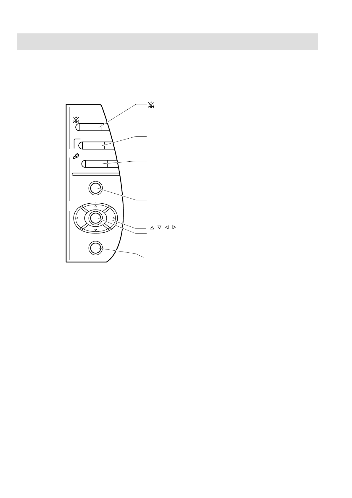
Panel Description
Control Panel
SILENCE
ALARMS
SILENCE ALARMS key
Silences the alarm sound.
NIBP
MENU
HELP
INTERVAL
START/STOP
NIBP INTERVAL key
Selects NIBP measurement mode. Pressing this key changes the mode.
NIBP START/STOP key
Starts NIBP measurement in the selected mode.
Pressing the key during measurement stops measurement.
MENU key
Opens the Main menu window.
, , , keys
Center key
Selects the items and menus on the screen and
performs various operations.
HELP key
Displays help on the screen.
Not available in this version.
1.16 Service Manual BSM-9510
Page 27
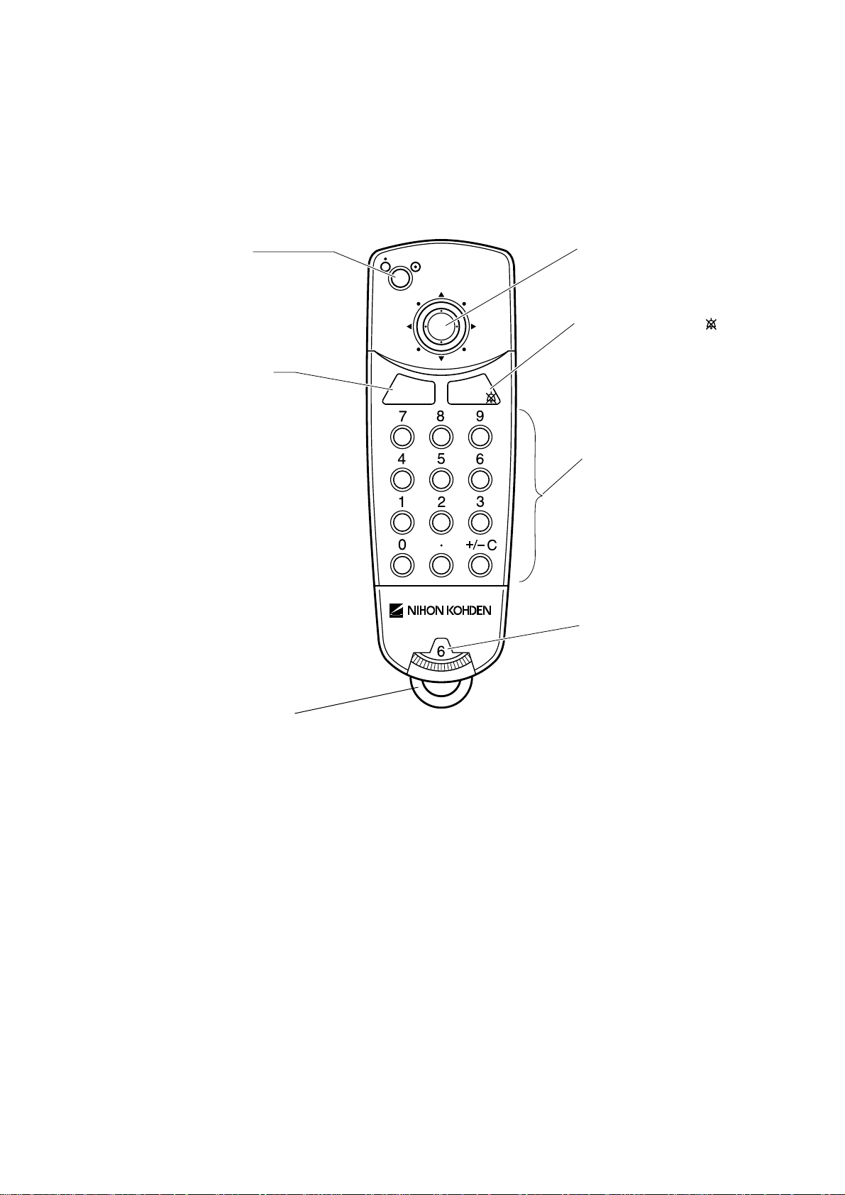
Remote Control
1. GENERAL
Power button
When the main power switch on
the rear panel is on, press this
button to turn the monitor
power on.
MENU key
Opens the Main menu
window.
MENU
SILENCE
ALARMS
Selection knob
Move this knob up/down/left/right and
press to select items and menus on the
screen.
SILENCE ALARMS key
Silences the alarm sound.
Numerical keys
For entering numbers and performing
shortcut key operations.
Monitor selection dial
Selects the monitor.
Loop
Attach a string or strap to hang the remote control.
Service Manual BSM-9510 1.17
Page 28
1. GENERAL
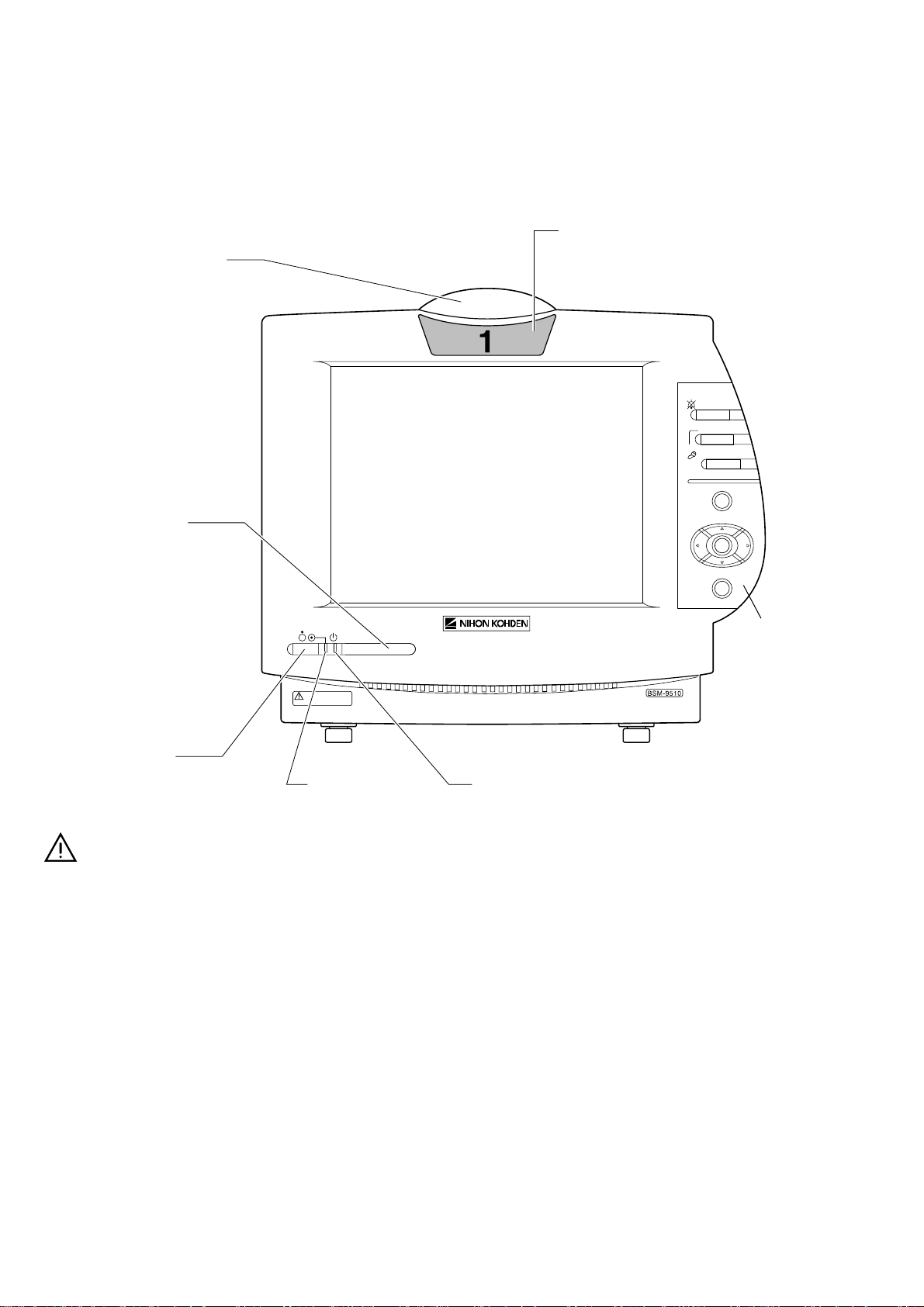
Main Unit
Front Panel
Alarm indicator
Blinks or lights when an
alarm is activated.
Remote control
sensor
Receives signal from
the remote control.
Always keep it clean.
Remote control channel label
Corresponds to the monitor selection
dial on the remote control.
SILENCE
ALARMS
INTERVAL
NIBP
START/STOP
MENU
HELP
Front power switch
When the main power switch on the
rear panel is on, press this switch to
turn the monitor power on.
Press and hold the front power switch
for more than 1 second to turn the
power off.
Power lamp
Lights when the main
power switch on the
rear panel and the front
power switch on the
front panel are on.
Control panel
Main power lamp
Lights when the main power switch
on the rear panel is on.
1.18 Service Manual BSM-9510
Page 29
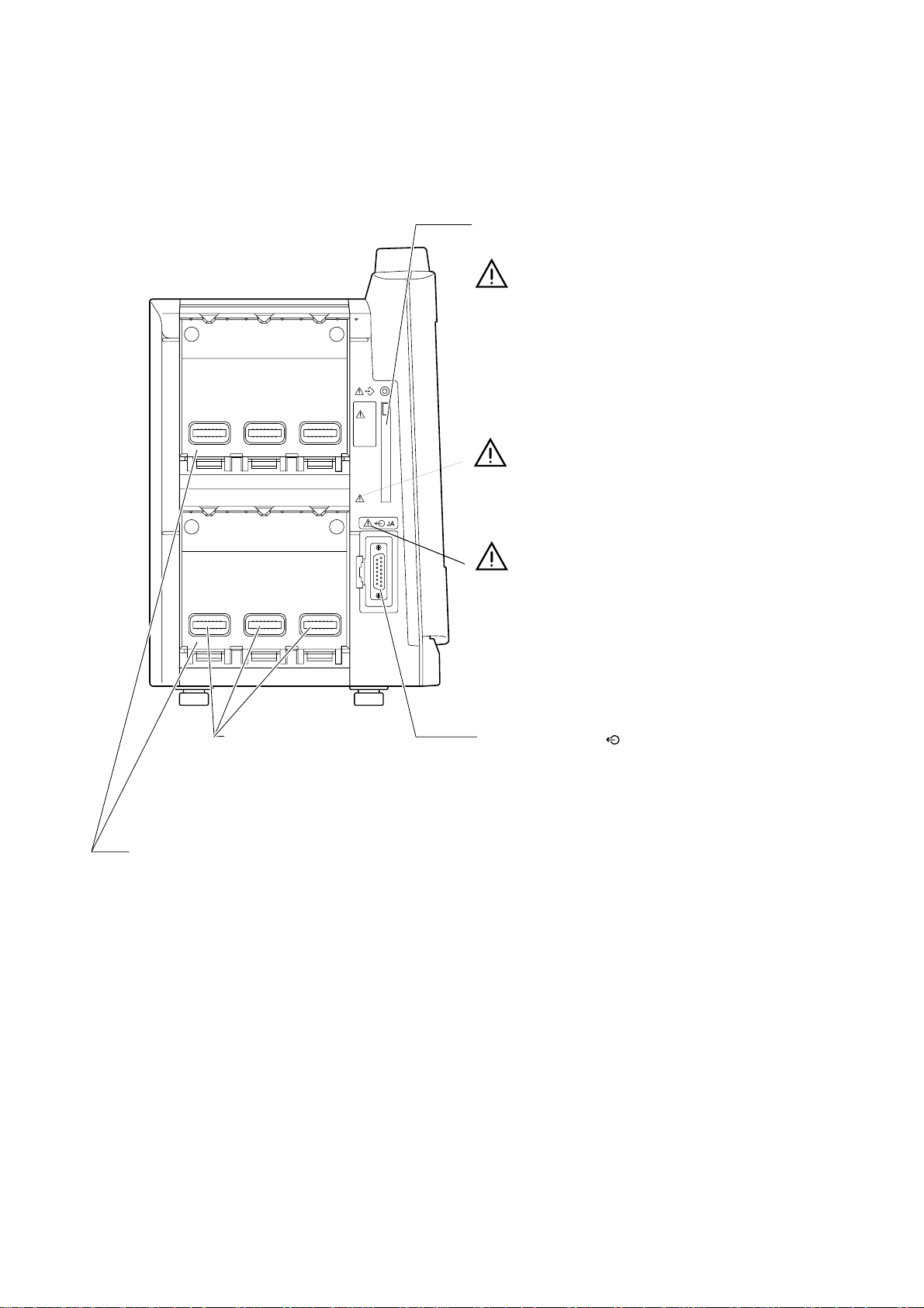
Left Side Panel
1. GENERAL
Memory card slot
For a memory card for upgrading the monitor software.
Do not eject the memory card or turn off the monitor while the
memory card lamp is lit. This may damage the memory card
and stored data.
Only use the specified memory card.
Only use the AY-900PA/910PA multi parameter module,
AA-900PA smart module, AG-900PA CO
WA-920PA recorder module and EK-900P blank module.
module,
2
Module connectors
Connect to the sockets on the module.
CAUTION
Do not open the connectors.
Otherwise you may receive
electrical current or the monitor
Slots
For the modules.
Insert EK-900P blank modules
in empty slots to prevent dust from
accumulating on the connectors.
may be damaged.
Refer to the cautions in "Connecting the System" in
Section 3.
JA output socket ( )
Connects to an input box or unit using the JA connection cable.
Not available in this version.
NOTE
Cover the socket when not in use to prevent dust from
getting inside the monitor.
Service Manual BSM-9510 1.19
Page 30
1. GENERAL
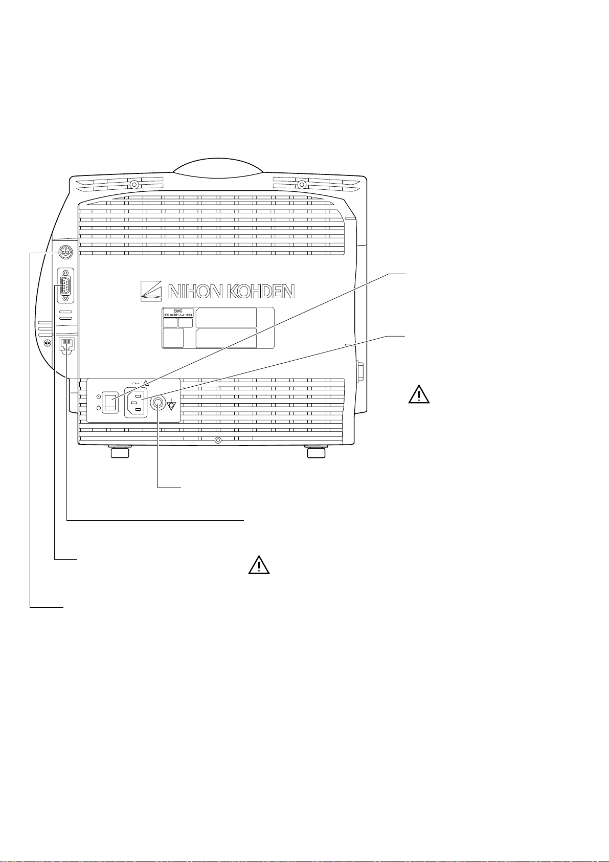
Rear Panel
Main power switch
Turns the main power on or off.
Equipotential terminal
Connects to the equipotential ground cable.
SERIAL socket
Connects to a PC.
Not available in this version.
ALARM socket
Connects to the optional alarm pole.
Power socket
Connects to a wall outlet using the
power cord to supply AC to the
monitor.
Refer to the cautions in "Connecting
the Power Cord and Grounding
the Monitor" in Section 3.
NETWORK socket
Connects to the 10 BASE-T cable of the network.
Not available in this version.
NOTE
Do not touch the NETWORK socket when you have static
electricity on your hand.
Cover the NETWORK socket when not in use.
1.20 Service Manual BSM-9510
Page 31

1. GENERAL
Multi Parameter Module
1
6
AY-900PA is for Nihon Kohden SpO2 probes.
AY-910P A is for Nellcor SpO2 probes.
CAUTION
When pressing the keys on the module, use your finger. Do not press
the keys with a sharp object. Otherwise keys may be broken.
2
3
4
5
9
10
Refer to the warning and
cautions on the next page.
8
No. Name Description
1 ECG/RESP key Press to open the ECG window.
2SpO
3 NIBP key Press to open the NIBP wind ow and change the NIBP measurement mode.
4 START/ STOP key
5
6 ECG RESP socket Connects to the ECG connection cord.
7SpO
8 NIBP socket Connects to the air hose.
key Press to open the SpO2 window.
2
Measures the NIBP in the selected mode. Pressing again during measurement
stops measurement.
MULTI 1, MULTI 2
keys
socket Connects t o the SpO2 connection cord.
2
Press to open the windows of the para meters connected to the MULTI 1 or
MULTI 2 socket.
7
Connects to the connection cord of the parameter to be measured (IBP,
MULTI 1, MULTI 2
9
sockets
ECG/BP OUT
10
socket
temperature, CO, CO
parameter is automatically r ecognized. When using the BP output signal, use
the MULTI 1 socket.
Outputs 100 mmHg/V IBP waveform of the pressure connected to the MULTI
1 socket, 1 mV/V ECG waveform of the first trace and heart rate trigger.
Refer to the below warning.
, FiO2 or respi ration by t hermistor met hod). The type of
2
Service Manual BSM-9510 1.21
Page 32

1. GENERAL
Using the Output Signal from the ECG/BP OUT Socket
WARNING
When using the output signal from the module as the synchronization
signal for other equipment such as IABP (intra-aortic balloon pump) or
defibrillator:
••
• Set the timing of the other equipment by checking the waveform on
••
the monitoring screen.
••
• Check the condition of the bedside monitor at all times. The output
••
signal may become unstable.
••
• The hum filter is always set to on for the ECG output. ECG output
••
differs from the ECG on the monitor screen regardless of the filter
setting.
••
• Check that the delay time of the output signal (heart rate trigger 100
••
ms maximum) is within the range of the connected equipment. Refer
to Section 11 of the operator’ s manual.
••
• Do not use the heart rate trigger as the synchronization signal for
••
defibrillator.
NOTE
The output signal from the ECG/BP OUT socket may become unstable
in the following conditions.
••
• Electrode is dry or detached.
••
••
• Electrode lead is damaged or disconnected from the electrode.
••
••
• Electrode lead is pulled.
••
••
• AC interference or EMG noise superimposed.
••
••
• Air bubbles or blood clog in the circuit for monitoring IBP.
••
••
• Any cord or cable disconnected or damaged.
••
Using MUL TI Soc kets f or CO and CO2 Monitoring
WARNING
••
• When performing defibrillation during CO monitoring, never touch the
••
CO connection cord. Otherwise the discharged energy may cause
serious electrical burn, shock or other injury.
••
• When performing defibrillation during CO2 monitoring with the TG-
••
900P CO2 sensor kit, remove the sensor from the patient. When the
sensor cannot be removed, do not touch the sensor cable because the
discharged energy may cause serious electrical burn, shock or other
injury.
NOTE
••
• CO monitoring using the MULTI socket does not compl y with the
••
Defibrillator proof type CF.
••
• CO2 monitoring using the MULTI socket does not comply with the
••
Defibrillator proof type BF.
1.22 Service Manual BSM-9510
Page 33

Smart Module
1. GENERAL
CAUTION
When pressing the keys on the module, use your finger. Do not press
the keys with a sharp object. Otherwise keys may be broken.
MULTI 1, MULTI 2 key
Press to open the windows of the parameters
connected to the MULTI 1 or MULTI 2 socket.
MULTI
MULTI 1, MULTI 2 socket
Connects to the connection cord of the
PRESS/TEMP/CO
CO2/FiO2/RESP
parameter to be measured from IBP,
temperature, CO, CO
, FiO2 and respiration
2
by thermistor method. The type of parameter is
automatically recognized.
Refer to the warnings and cautions below.
Using MULTI Sockets for CO and CO2 Monitoring
WARNING
••
• When performing defibrillation during CO monitoring, never touch the
••
CO connection cord. Otherwise the discharged energy may cause
serious electrical burn, shock or other injury.
••
• When performing defibrillation during CO2 monitoring with the TG-
••
900P CO2 sensor kit, remove the sensor fr om the patient. When the
sensor cannot be removed, do not touch the sensor cable because the
discharged energy may cause serious electrical burn, shock or other
injury.
NOTE
••
• CO monitoring using the MULTI soc ket does not compl y with the
••
Defibrillator proof type CF.
••
• CO2 monitoring using the MULTI socket does not comply with the
••
Defibrillator proof type BF.
Service Manual BSM-9510 1.23
Page 34

1. GENERAL
Recorder Module
SET UP key
Opens the
Record Setup window.
Recording lamp
Lights during recording.
START/STOP key
Press to start or stop recording.
ERROR lamp
Lights when recording error occurs.
Paper magazine
release lever
Pull up the lever to open
the paper magazine.
SET UP
START/STOP
ERROR
Paper magazine
For recording paper.
1.24 Service Manual BSM-9510
Page 35

Connection Diagram
1. GENERAL
Service Manual BSM-9510 1.25
Page 36

1. GENERAL
Block Diagram
1.26 Service Manual BSM-9510
Page 37

Section 2 T roubleshooting
T roubleshooting T able ..........................................................................................................2.1
How to Use the Troubleshooting Table .............................................................2.1
Po wer-Related Problem .............................................................................................2.2
Display Problems ......................................................................................................2.2
Sound Problem .........................................................................................................2.2
Ke y Operation Prob lem s............................................................................................2.3
Recorder Problem .....................................................................................................2.3
Other Module-Related Problem .................................................................................2.3
Service Manual BSM-9510 2C.1
Page 38

T roubleshooting T able
Use the troubleshooting table to locate, identify and solve a problem in the
instrument. The problems are divided into general problem areas. Each category
has its own troubleshooting table for fast and easy troubleshooting.
• Power-Related Problems
• Display Problems
• Sound Problems
• Key Operation Problems
• Recorder Problems
• Other Module-Related Problems
Refer to Section 21 “Maintenance” in the operator’s manual.
2. TROUBLESHOOTING
How to Use the Troubleshooting Tab le
1. Determine which troubleshooting table to use.
2. In the “Problem” column, find the trouble item that matches the problem.
3. Do the action recommended in the “Action” column.
4. If the problem is not solved, do the action for the next possible cause or
criteria.
5. If none of the actions solve the problem, contact your Nihon Kohden
representative.
Service Manual BSM-9510 2.1
Page 39

2. TROUBLESHOOTING
Power-Related Problem
Problem Possible Cause/Criteri a Action
The power of the
main unit does not
turn on.
The AC power switch on the rear panel is set to off. Set the AC power switch to on.
When the standby lamp does
not light ev en if t he AC
power switch is set to on.
It happens after the main unit
is assembled.
Display Problems
Problem Possible Cause/Criteria Action
No AC power input. Check the AC power input.
Faulty power cord. Replace the power cord.
One or both of the AC inlet fuses are
blown.
Faulty power supply unit. Replace the power supply unit.
Poor internal connection. Check the conti nuity of cables and boards.
Determine and correct the cause of the
blown fuse, then replace the fuse.
No display.
The screen is distorted or
partially abnormal.
Diagnostic Check and System
Setup screen is displayed.
System error is displayed. Faulty MAIN board. Replace the MAIN board.
NIBP START/STOP key on th e
control panel is operational with AY900PA/910PA.
The power lamp does not light. Faulty MAIN board. Replace the MAIN board.
The same part* of the LCD has an
abnormal on any screen.
The LCD unit has an abnormal on
specified Display Check screens.
The error message is shown at the Power ON Check Result on the
screen.
Faulty LCD unit. Replace t he LCD unit.
Faulty DC-AC inverter. Replace t he DC-AC inv erter.
Faulty MAIN board. Replace the MAIN board .
Faulty LCD unit. Replace t he LCD unit.
Faulty MAIN board Replace the MAIN board.
Replace the board co nsidered faul ty
with the error mess age.
* For TFT LCD screen, it is considered normal if some pixels have abnormal color or do not light.
Sound Problem
Problem Possible Cause/Criteria Action
No sound. Poor contact between the speaker and power supply
unit.
Faulty power supply unit. Replace the power s upply unit.
Faulty MAIN board. Replace the MAIN boar d.
2.2 Service Manual BSM-9510
Check the continuity of the connection cable and socket at
the power supply unit.
Page 40

Key Operation Problems
Problem Possible Cause/Criteri a Action
2. TROUBLESHOOTING
No key operation. Any key is not operat ional.
Specified key i s not
operational.
No remote control
operation.
Any key is not operational. Remote control channel is set to a
Specified key i s not
operational.
Poor internal connection.
Faulty OPERATION board. Replace the OPERATION board.
Faulty MAIN board. Replace the MAIN board.
The key on the IR DETECT boar d. Replace the I R DETECT board.
The key on the MAIN board. Replace the MAIN board.
specified cahnnel.
The two batteries ar e weak. Replace the t wo batteries.
Faulty IR DETECT board. Replace the IR DETECT board.
Faulty remote control. Replace the remote control.
Faulty key switch on the remote control. Replace the remote control.
Check the continuity of the cables and
boards in bet ween.
Confirm which channel is set on the
Setup Menu window.
Recorder Problem
Problem Possible Cause/Criteria Action
No operation of the
recorder module.
There is an error at
JA I/F Check.
There is no error at
JA I/F Check.
Faulty JA motherboard. Replace the JA motherboard.
Faulty MAIN board. Replace the MAIN board.
Poor insertion of the reco rder module.
Faulty recorder module. Replace the r ecorder module.
Complete ly insert the recorder moule into the
slot.
Other Module-Related Problem
Problem Possible Cause/Criteria Action
No wavef orm
display.
Any waveform is not
displayed on the screen.
Waveform of the
specified parameter is not
displayed.
Faulty JA motherboard. Replace the J A motherboard.
Breaking of the input cable or faulty connector,
sensor, transd ucer.
Faulty module. Replace the module.
Replace the corr esponding cable.
Faulty slot. Replace the JA motherboard.
Service Manual BSM-9510 2.3
Page 41

Section 3 Diagnostic Check
Introduction .........................................................................................................................3.1
P ow er On Self Chec k ..........................................................................................................3.2
Calling up the Diagnostic Check and System Setup Screen ...............................................3. 3
MU Manual Check...............................................................................................................3.5
Memory Check..........................................................................................................3.5
Flash ROM (program) Check ..........................................................................3.6
Flash ROM (data) Check.................................................................................3.6
SRAM Check ..................................................................................................3.6
DRAM Check ..................................................................................................3. 7
Com Check ...............................................................................................................3.7
Network I/F Check ..........................................................................................3.8
Serial I/F Check ............................................................................................3.10
JA I/F Check.................................................................................................3.10
Display Check.........................................................................................................3.13
Frame Mem Chec k........................................................................................3.13
Graphic Check ..............................................................................................3.14
Waveform Check...........................................................................................3.14
Backlight Check............................................................................................3.14
Ke y LED Check.......................................................................................................3.15
Key Check ....................................................................................................3.15
Remote Check ..............................................................................................3.16
Alarm Indicator Check...................................................................................3.16
Alarm Pole Check .........................................................................................3.17
Other Check............................................................................................................3.17
Sound Check ................................................................................................3.1 8
P ower Chec k.................................................................................................3.1 8
Card I/F Check..............................................................................................3.1 8
Timer IC Check.............................................................................................3.1 9
Service Manual BSM-9510 3C.1
Page 42

Introduction
3. DIAGNOSTIC CHECK
The instrument has an automatic power on self check as well as a complete set of
diagnostic checks that you can perform at any time.
All errors detected during the power on self check, diagnostic checks, and any time
during operation are stored in the error history table.
The diagnostic checks, error history, system setup, and initialization are accessed
from the Diagnostic Check and System Setup screen.
In this section, functions which are displayed on the screen are indicated by
brackets, for example, the [Monitor Mode] function on the Diagnostic Check and
System Setup screen.
Service Manual BSM-9510 3.1
Page 43

3. DIAGNOSTIC CHECK
P o wer On Self Chec k
Chec k Item How to Che ck Act ion at Erro r Occu rre nce
This self check is performed every time the power switch on the front panel is
turned on. “Check Program Running” message appears during the power on self
check. If no error is detected, the normal operating mode begins and the patient
monitoring display appears. If an error is detected, the screen displays one of the
following items according to the check items.
Flash ROM Check
for system program
DRAM Check The test patterns written to the DRAM are compared
Flash ROM Check
for Setting Conditions
JA RAM Check The test patterns written on the JA RAM are
SRAM Backup
Check
Timer IC Memory
Backup Check
The sum of the stored data from the beginning
address to the last se cond address is compared with
the prestored check sum at the last address.
with the test patterns which were read out from the
DRAM.
The data which is read out from the flash ROM is
compared with the fixed data.
compared with the test patterns which were read out
from the JA RAM.
The data read out from the SRAM is compared wit h
the previous data which was written on the SRAM.
The data read out from the real time clock IC builtin memory is checked.
The check is interrupted. An error message is
displayed.
The check is interrupted. An error is dis played.
The flash ROM is initialized and its message is
displayed. Next check item follows.
An error message is displayed. Next check item
follows. After the power on self check, the
Diagnostic Chec k and Syste m Setup scre en appears.
The SRAM is initialized and its message is
displayed. Next check item follows.
The real time clock IC built-in memory is initialized
and its message is displayed. Next check item
follows.
3.2 Service Manual BSM-9510
Page 44

3. DIAGNOSTIC CHECK
Calling up the Diagnostic Check and System Setup Screen
1. With the power off, pr ess the power switch on the front panel while pressing
the SILENCE ALARMS key on the control panel. Continue pressing the
SILENCE ALARMS key until the Diagnostic Check and System Setup screen
appears.
Power ON Check Result: When no error is found during the power on self
check, OK is displayed. If an error is found during
the power on self check, ERROR and the c heck item
at which the error is found are displayed.
MU: Shows model number of the main unit, system
program version, and boot program version
Module: Shows model numbers and software versions of the
modules inserted into the slots of the main unit.
EXT JA: Shows description of the optional unit connected to
the EXT JA soc ket.
Module (EXT JA): Shows model number and software version of any
optional unit connected to the EXT JA socket of the
main unit.
While this screen is displayed, the connection check
results of Module, EXT JA , Module (EXT JA) are
updated in real time.
2. To exit the Diagnostic Check and System Setup screen and return to the
patient monitoring mode, select the [Monitor Mode] using the left or right
arrow key on the control panel and pressing the center key on the control
panel.
Service Manual BSM-9510 3.3
Page 45

3. DIAGNOSTIC CHECK
To perform the diagnostic c he ck, system setup, or initialization or to view the
error history, select one of the functions at the bottom of the screen using the
left or right arrow key on the control panel and pressing the center key on the
control panel.
Diagnostic Check and System Setup
Flash ROM (program)
Flash ROM (data)
SRAM Check
DRAM Check
JA Manual CheckMU Manual Ceck
Network I/F Check
Serial I/F Check
JA I/F Check
Frame Mem Chec k
Graphic Check
Wav ef orm Check
Backlight
Check
Error HistorySystem Setup
Key Check
Remote Check
Alarm Indicator Check
Alarm Pole
Check
System Initialize
5. Other Check4. Key LED Check3. Display Check2. COM Check1. Memory Check
Sound Check
Po wer Chec k
Card I/F Check
Timer IC Check
3.4 Service Manual BSM-9510
Page 46

MU Manual Check
3. DIAGNOSTIC CHECK
Select [MU Manual Check] using the left or right arrow key on the control panel
and pressing the center key on the control panel. The MU Manual Check screen
appears.
On the screen, using the up or down arrow key on the control panel and pressing
the center key on the control panel allows you to select the various function check
screens. To return to the Diagnostic Check and System Setup screen, select
[Return].
*** MU Manual Check ***
Memory Check
Com Check
Display Check
Key LED Check
Other Check
Return
Memory Check
On the MU Manual Check screen, select [Memory Check]. The Memory Check
screen, which checks the memory on the MAIN board, appears. On the Memory
Check screen, the following checks are available. To return to the MU Manual
Check screen, select [Return].
*** Memory Check ***
Flash ROM (program) Check
Flash ROM (data) Check
SRAM Check
DRAM Check
Return
Service Manual BSM-9510 3.5
Page 47

3. DIAGNOSTIC CHECK
Flash ROM (program) Check
This screen allows you to check if the program stored in the flash memory has an
error.
To start the check, select [Start]. “Checking…” message is displayed during the
check. After the check, OK or Error appears.
To return to the Memory Check screen, select [Return].
*** Flash ROM (program) Check ***
Checking . . .
Start
Return
Flash ROM (data) Check
This screen allows you to check if the writable area of the flash memory has an
error by writing test data and reading it after deleting the original data.
To start the check, select [Start]. A “Erasing…” message is displayed while the
data is being deleted. After the data is deleted, OK appears. A “Checking…”
message is displayed during the check. After the check, OK or Error appears.
To return to the Memory Check screen, select [Return].
*** Flash ROM (data) Check ***
Checking . . .
Start
Return
SRAM Check
This screen allows you to check if the SRAM has an error by writing test data and
reading it after deleting the original data.
To start the check, select [Start]. A “Checking…” message is displayed during the
check. After the check, OK or Error appears. If an error occurs, the Er ror is
displayed with the address.
To return to the Memory Check screen, select [Return].
3.6 Service Manual BSM-9510
Page 48

3. DIAGNOSTIC CHECK
*** SRAM Check ***
Checking . . .
Start
Return
DRAM Check
This screen allows you to check if the DRAM has an error by writing test data and
reading it after deleting the original data.
To start the check, select [Start]. A “Checking…” message is displayed during the
check. After the check, OK or Error appears. If an error occurs, the Error is
displayed with the address.
To return to the Memory Check screen, select [Return].
Com Check
*** DRAM Check ***
Checking . . .
Start
Return
On the MU Manual Check screen, select [Com Check]. The Com Check screen,
which checks each communication interface on the MAIN board, appears. On the
Com Check screen, the following checks are available. To return to the MU
Manual Check screen, select [Return].
*** Com Check ***
Network I/F Check
Serial I/F Check
JA I/F Check
Return
Service Manual BSM-9510 3.7
Page 49

3. DIAGNOSTIC CHECK
Network I/F Check
This screen allows you to check the network interface, interface loopback, and
network connection.
*** Network I/F Check ***
MAC Address . . . 00A02Axxxxxx
Reply
Traffic
Return
Reply Check
This screen displays the MAC addresses of which the other bedside monitors (up to
48 monitors) in the network transmit the acknowledge signals to this bedside
monitor.
*** Reply Check ***
00A02Axxxxxx 00A02Axxxxxx 00A02Axxxxxx
00A02Axxxxxx 00A02Axxxxxx 00A02Axxxxxx
00A02Axxxxxx 00A02Axxxxxx 00A02Axxxxxx
.
.
.
.
Return
.
.
.
.
.
.
.
.
T raff ic Check
This screen displays the traffic status in the network when test data is uploaded to
the network.
*** Traffic Check ***
Return
3.8 Service Manual BSM-9510
Page 50

3. DIAGNOSTIC CHECK
MAC Addr ess Write
Since this function is hidden, press the SILENCE ALARMS key on the control
panel to display the [Adr WR] in addition to the [Reply] and [Traffic] functions on
the Network I/F Check screen. Select the [Adr WR] to display the MAC Address
Write screen which allows you to change the MAC address of the bedside monitor.
Use the up, down, left, or right arrow key on the control panel to move the cursor to
the following items in the table. Press the center key on the control panel to
execute the item.
Network I/F Check screen when the SILENCE ALARMS key is pressed
*** Network I/F Check ***
MAC Address . . . 00A02Axxxxxx
Adr WR
Reply
Traffic
Return
*** MAC Address Write ***
00A09Axxxxxx
3
0A1B2
5F6
4
D
C
E
78
Save Cancel
9
0 to F: Hexadecimal numbers for input of the MAC address
←, →: Moves the MAC address input position left or right.
Save: Stores the entered MAC address and returns the screen to the Network I/F
Check screen.
Cancel: Leaves the previous MAC address and returns the screen to the Network I/
F Check screen.
Service Manual BSM-9510 3.9
Page 51

3. DIAGNOSTIC CHECK
Serial I/F Check
This screen allows you to perform the loopback test of the serial interface RS-232C
under the following conditions by connecting the loopback tester* to the RS232C port.
Parity: None
Data length: 8 bits
Stop bit: 1 bit
Baud rate: 9600 bps
* Make the tester locally. Refer to figure xxx.
*** Serial I/F Check ***
OK
Start
Return
To start the check, select [Start]. A “Checking…” message is displayed during the
check. After the check, OK or Error appears.
To return to the Com Check screen, select [Return].
JA I/F Check
This screen allows you to check the communication interfaces for any modules and
external units.
The following checks are available.
*** JA I/F Check ***
RAM Check 1
Ram Check 2
Internal Loopback Check
External Loopback Check
CTL Check
Return
RAM Check 1
This screen allows you to check the RAM, which stores the communication data
between the modules and MAIN board, by writing the test data into the RAM and
reading the stored data from the RAM. The addresses 0000H to FFFFH (Bank 1)
and 0000H to 07FFH (Bank 2) are used for this check.
To start the check, select [Start]. “Checking…” message is displayed during the
check. After the check, OK or Error appears. If an error occurs, the Er ror is
displayed with the bank and address.
To return to the JA I/F Check screen, select [Return].
3.10 Service Manual BSM-9510
Page 52

3. DIAGNOSTIC CHECK
*** RAM Check 1 ***
Checking . . .
Start
Return
RAM Check 2
This screen allows you to check the RAM, which stores the communication data
between the modules and MAIN board, by writing the test data into the RAM and
reading the stored data from the RAM. The addresses 0000H to 03FFH (Bank A)
and 0400H to 07FFH (Bank B) are used for this check.
To start the check, select [Start]. A “Checking…” message is displayed during the
check. After the check, OK or Error appears. If an error occurs, the Error is
displayed with the bank and address.
To return to the JA I/F Check screen, select [Return].
*** RAM Check 2 ***
Checking . . .
Start
Return
Internal Loopback Check
NOTE
Remove all the modules from the main unit before starting the internal
loopback check.
This screen allows you to check the loopback from the JA motherboard by
transmitting 512 byte packet (all the data is either zero or one) to the JA
motherboard. When all the data is set to one, the source address changes to FEH.
To start the check, select [Start]. A “Checking…” message is displayed during the
check. When the data returns to the MAIN board within 5 ms after the data is
transmitted to the JA motherboard, OK a ppears. Otherwise, Error appears.
To return to the JA I/F Check screen, select [Return].
Service Manual BSM-9510 3.11
Page 53

3. DIAGNOSTIC CHECK
*** Internal Loopback Check ***
OK
Start
Return
External Loopback Check
NOTE
Connect the Loopback tester to the JA socket of the main unit before
starting the external loopback check.
This screen allows you to check the loopback from the EXT JA board by
transmitting a 512 byte packet (all the data is either zero or one) to the EXT JA
board. When all the data is set to one, the source address changes to FEH.
To start the check, select [Start]. A “Checking…” message is displayed during the
check. When the data returns to the MAIN board within 5 ms after the data is
transmitted to the EXT JA board, OK appears. Otherwise, Error appears.
To return to the JA I/F Check screen, select [Return].
*** External Loopback Check ***
OK
Start
Return
CTL Check
NOTE
Connect the loopback tester to the JA socket of the main unit before
starting the CTL check.
This screen allows you to check the control signal by transmitting it to the EXT JA
board every 16 ms.
To return to the JA I/F Check screen, select [Return].
3.12 Service Manual BSM-9510
Page 54

*** CTL Check ***
Return
3. DIAGNOSTIC CHECK
Display Check
On the MU Manual Check screen, select [Display Check]. The Display Check
screen, which checks the LCD functions, appears. On the Display Check screen,
the following checks are available. To return to the MU Manual Check screen,
select [Return].
*** Display Check ***
Frame Mem Check
Graphic Check
Waveform Check
Backlight Check
Return
Frame Mem Check
This screen allows you to check the graphic frame memory (character generation
area included) and waveform frame memory (waveform data buffer included) by
writing the test data into the memories and reading the stored data from the
memories.
To start the check, select [Start]. A “Checking…” message is displayed during the
check. After the check, OK or Error appears. If an error occurs, the Error is
displayed with the address.
To return to the Display Check screen, select [Return].
*** Frame Mem Check ***
OK
Start
Return
Service Manual BSM-9510 3.13
Page 55

3. DIAGNOSTIC CHECK
Graphic Check
This screen allows you to check the graphic screen display by displaying the
following screens.
To select them, use the up, down, left, or right arrow key on the control panel.
White whole screen → Red whole screen → Green whole screen → Blue whole
screen → “H” pattern screen → White whole screen
To return to the Display Check screen, press the center key on the control panel.
Waveform Chec k
This screen allows you to check the waveform screen display by displaying the
following screen.
There are 12 rectangular waveforms which show the waveform traces 1 to 6 on the
W1 screen and the waveform traces 1 to 6 on the W2 screen.
To return to the Display Check screen, select [Return].
A: 10 pixels
B: 100 pixels
C: 20 pixels
B
AAA
Waveform: white
Smoothing bit S1: red
Smoothing bit S2: blue
Smoothing bit S3: green
C
*** Waveform Check ***
. . . . . .
Return
Backlight Check
This screen allows you to check the backlight brightness control by displaying the
white whole screen.
Use the up or down arrow key on the control panel to increase or decrease the
brightness.
To return to the Display Check screen, press the center key on the control panel.
3.14 Service Manual BSM-9510
Page 56

3. DIAGNOSTIC CHECK
Key LED Check On the MU Manual Check screen, select [Key LED Check]. The Key LED Check
screen, which checks the keys and LED functions, appears. On the Key LED
Check screen, the following checks are available. To return to the MU Manual
Check screen, select [Return].
*** Key LED Check ***
Key Check
Remote Check
Alarm Indicator Check
Alarm Pole Check
Return
Key Check
This screen allows you to check the front power switch and the keys on the control
panel.
All the keys are displayed on the screen. Press one of the keys and confirm that
the corresponding key display is reverse shaded in the color on the screen. If not,
the key may have a failure.
If the center key has no failure, the screen returns to the Key LED Check screen
after the corresponding key display is reverse shaded when the center key on the
control panel is pressed.
NOTE
Pressing the front power switch does not turn off the main unit in this
check.
*** Key Check ***
SILENCE ALARMS
MENU
HELP
Press and hold MENU key to return
NIBP INTERVAL
NIBP START/STOP
Service Manual BSM-9510 3.15
Page 57

3. DIAGNOSTIC CHECK
Remote Check
This screen allows you to check the keys on the remote control.
All the keys are displayed on the screen. Press one of the keys and confirm that
the corresponding key display is reverse shaded in the color on the screen. If not,
the key may have a failure.
If the selection knob has no failure, the screen returns to the Key LED Check
screen after the corresponding key display is reverse shaded when the selection
knob is pressed at the center of its position.
Pressing the center key on the control panel is another way to return to the Key
LED Check screen.
NOTE
Pressing the power button does not turn off the main unit in this check.
*** Remote Check ***
MENU
ALARM
89
7
4
5
6
3
12
.
+
0
Press and hold MENU key to return
MENU
/
-
Alarm Indicator Check
This screen allows you to check the LEDs of the alarm indicator.
To select the LED color (red or yellow), use the up, down, left, or right arrow key
on the control panel. The selected color LEDs blink at the alarm indicator.
To return to the Key LED Check screen, press the center key on the control panel
so that [Return] is executed
*** Alarm Indicator Check ***
YELLOW
Return
3.16 Service Manual BSM-9510
Page 58

3. DIAGNOSTIC CHECK
Alarm Pole Check
This screen allows you to check the LEDs of the optional alarm pole.
Connect the alarm pole to the main unit and use the up, down, left, or right arrow
key on the control panel to select the color (red, yellow, or green). The selected
color LEDs blink at the alarm pole.
To return to the Key LED Check screen, press the center key on the control panel
so that [Return] is executed.
*** Alarm Pole Check ***
YELLOW
Return
Other Check
On the MU Manual Check screen, select [Other Check]. The Other Check screen
appears. On the Other Check screen, the following checks are available. To
return to the MU Manual Check screen, select [Return].
*** Other Check ***
Sound Check
Power Check
Card I/F Check
Timer IC Check
Return
Service Manual BSM-9510 3.17
Page 59

3. DIAGNOSTIC CHECK
Sound Check
This screen allows you to check the FM sound source and audio amplifier. The
following checks are available.
*** Sound Check ***
Sound 1
Sound 2
Sound 3
Sound 4
Sound 5
Return
[Sound 1]: Generates each alarm sound continuously.
[Sound 2] to [Sound 5]: Generate a musical scale of one octave. Sound 2 is
lowest pitch. The difference between Sound 2 and Sound
3, between Sound 3 and Sound 4, and between Sound 4
and Sound 5 is one octave.
[Return]: Returns to the Other Check screen.
Power Chec k
This screen allows you to check the status signals from the power supply unit and
24 V for an external unit in future. The following checks are available. This
screen checks each status (AC fail status, AC line frequency automatic detection,
+24 V over current fail status) in real time.
To return to the Other Check screen, press the center key on the control panel so
that [Return] is executed.
*** Power Check ***
ACFAIL Status OK
AC Frequency 50 Hz
+24 V Over Current OK
Return
Card I/F Check
This screen allows you to check the memory card interface by writing the test data
into the memory card and reading the stored data from the memory card.
To start the check, insert the optional memory card into the slot of the main unit
and select [Start]. A “Checking…” message is displayed during the check. After
the check, OK or Error appears. If an error occurs, the Error is displayed with the
address.
To return to the Other Check screen, select [Return].
3.18 Service Manual BSM-9510
Page 60

3. DIAGNOSTIC CHECK
*** Card I/F Check ***
Insert QM-010P (1 MB SRAM)
OK
Start
Return
Timer IC Check
This screen allows you to check the memory of the real time clock IC by writing
the test data into the memory and reading the stored data from the memory. The
current time is displayed on the screen. Before the check, the previous data stored
into the memory is backed up. The backed-up data is written into the memory
again when the screen returns to the Other Check screen after the check.
To start the check, select [Start]. A “Checking…” message is displayed during the
check. After the check, OK or Error appears. If an error occurs, the Error is
displayed with the address.
To return to the Other Check screen, select [Return].
*** Timer IC Check ***
Timer 1999/06/14 17:24:46
Memory OK
Start
Return
Service Manual BSM-9510 3.19
Page 61

Section 4 Board/Unit Description
Signal Flow .........................................................................................................................4.1
Vital Sign Signals from Patients................................................................................4.1
Display Data .............................................................................................................4.1
Pow er Control Signal b y Front Pow er Switch or Power Button on
Optional Remote Control ......................................................................................4.1
MAIN Board UR-3485 ..........................................................................................................4.2
EXT JA Board UR-3489 ......................................................................................................4.2
JA Motherboard UR-3486 ....................................................................................................4.2
IR DETECT Board UR-3487 ................................................................................................4.3
LCD JUNC Board UR-3504 ..................................................................................................4.3
LED Board UR-3393 ............................................................................................................4.3
OPERA TION Board UR-3506...............................................................................................4.3
P ower Supply Unit SC-036R................................................................................................4.4
Service Manual BSM-9510 4C.1
Page 62

Signal Flow
4. BOARD/UNIT DESCRIPTION
Vital Sign Signals from
Patients
Display Data
The vital sign signals such as ECG/respiration wave, plethysmographic pulse
wave, blood pressure waveform, and NIBP go to the modules through the electrode
leads, sensor probe, transducer, and cuff and tube. These signals are digitized in
the modules. The digitized data is transferred to the MAIN board through the JA
motherboard.
On the MAIN board, the CPU writes the binary code waveform data into the WAVE
RAM area of the CRT controller (gate array IC). The CRT controller converts the
waveform data to graphic data and writes it into the WAVE RAM area. The CPU
writes alphanumeric data and review data such as trendgraph into the GRAPH
RAM area of the CRT controller. The CRT controller mixes the data in the WAVE
RAM and GRAPH RAM area to create the display data for screen. The CR T
controller converts the displa y data to RGB signals which go to the LCD unit.
Po wer Control Signal by
Front P ower Switch or
Power Button on Optional
Remote Control
When the AC power switch on the rear panel is set to on, the BSM-9510 is on
standby. The MAIN board outputs the power control signal to the power supply
unit when the power switch on the front panel or power button on the optional
remote control is pressed during standby. The power control signal allows the
BSM-9510 to turn on or be on standby.
Service Manual BSM-9510 4.1
Page 63

4. BOARD/UNIT DESCRIPTION
MAIN Board UR-3485
The MAIN board has one 68EN360 which is used as the CPU of the BSM-9510.
The CPU clock is 25 MHz.
The following components are mounted on this board.
• Flash memory for system program:Has the ROM and RAM area on which the
system program runs.
• Flash E2PROM: Included in the flash memory. Stores the
conditions set on the System Setup screen.
• Real time clock (R TC): Used for date and time.
• Key operation controller: Reads the status of the front power switch and
each key on the control panel
• Ethernet driver: Used for local area network LAN.
• RS232C driver: Used for communication with an external unit
in future or a personal computer.
• CRT controller: Converts the screen data to RGB signals and
outputs them to the LCD unit.
EXT JA Board UR-3489
This daughter board has a socket for connection of external units in the future and
is mounted on the MAIN board.
JA Motherboard UR-3486
This board has 6 sockets for modules. This board is connected to the MAIN board.
The MAIN board communicates with the modules through this board. External
units in the future will also communicate with the MAIN board through the EXT
JA board and this board.
4.2 Service Manual BSM-9510
Page 64

IR DETECT Board UR-3487
This board has the infrared sensor for remote control and outputs the remote
control signals to the MAIN board.
LCD JUNC Board UR-3504
This daughter board is mounted on the LCD unit and converts the signals from the
MAIN board to the LCD unit.
4. BOARD/UNIT DESCRIPTION
LED Board UR-3393
This board has LEDs for alarm indicator and is mounted inside the top of the
display.
OPERATION Board UR-3506
This board has switches for key operation and is mounted into the control panel.
Service Manual BSM-9510 4.3
Page 65

4. BOARD/UNIT DESCRIPTION
P ower Supply Unit SC-036R
The power supply unit has the following outputs.
• +5V
• +5VS constant voltage output: Used for the front power switch activation in
• +12VU constant voltage output: Used for the LCD backlight and alarm indicator
• +VJA constant voltage output: Used for the JA motherboard and modules.
• +24VC constant voltage output: Will be used for future external units.
The power switch on the front panel turns on or off the outputs except +5VS when
the +5VS output is turned on. If the +5VS output is turned off, the power switch has
no function. The AC power switch on the rear panel turns on the +5VS output only
or turns it off together with the other outputs.
When an external unit (future) is connected to the socket, the +24VC output is
turned on.
This power supply unit allows BSM-9510 to resume monitoring after power
recovery if the BSM-9510 has momentary power loss during monitoring.
constant voltage output: Used for all the digital circuits.
D
standby mode.
LEDs
4.4 Service Manual BSM-9510
Page 66

Section 5 Disassembly and
Assembly
Before Y ou Begin.................................................................................................................5.1
Warnings and Cautions..............................................................................................5.1
Required T ools...........................................................................................................5.1
Replacing MAIN Board ........................................................................................................5. 2
Replacing Fuse ...................................................................................................................5.5
Replacing Po wer Supply Unit ..............................................................................................5.7
Replacing JA Motherboard ................................................................................................5.10
Replacing IR DETECT Board ............................................................................................5.13
Replacing LCD Unit ...........................................................................................................5.16
Replacing DC-AC In verter .................................................................................................5.19
Replacing Backlight Lamps...............................................................................................5.2 2
Replacing LCD Filter..........................................................................................................5.26
Replacing OPERATION Board...........................................................................................5.29
Replacing Lithium Battery .................................................................................................5.32
Service Manual BSM-9510 5C.1
Page 67

Before Y ou Begin
Warnings and Cautions
5. DISASSEMBLY AND ASSEMBLY
The procedures in this section tell how to remove, replace and install major
components in the instrument.
Removing, replacing and installing major components should be done by
qualified service personnel.
W ARNINGS
••
• To avoid the possibility of injury to yourself or damage to the
••
instrument, do not install or remove any component or change switch
settings while the power is on and wait 10 minutes after the power is
off before installing or removing any component from the instrument.
••
• To a v oid accidental dischar ge of static electricity whic h could damage
••
the instrument components, use a wrist ground strap when installing
or removing any component of the instrument.
Required T ools
CAUTIONS
••
• Before connecting or disconnecting any cables, turn off the instrument
••
and unplug the AC power cord fr om the instrument.
••
• Fuses cut off the power when an abnormality occurs in the instrument.
••
Eliminate the malfunction before replacing the fuse. Use the correct
fuse* only . The fuse rating is shown on the printed circuit board of the
power supply unit.
••
• Removal and replacement of any component in the instrument should
••
be done by qualified service personnel.
••
• Use only parts recommended by Nihon Kohden to assure maximum
••
performance from your instrument.
* Refer to Section 8 “Replaceable Parts List”.
• Anti-static bench mat
• Wrist ground strap
• M3 Phillips screwdriver (insulated type)
• M4 Phillips screwdriver (insulated type)
• Small flat-blade screwdriver (insulated type)
Service Manual BSM-9510 5.1
Page 68

5. DISASSEMBLY AND ASSEMBLY
Replacing MAIN Board
1. Loosen the 2 screws (M4 binding head screws) at the bottom of the main unit.
Screws
2. Remove the 2 screws (M4 binding head screws) at the top of the rear cover and
the screw (M3 pan head screw with spring washer) at the rear of the control
panel.
3. Slightly pull out the front cover assy until the 2 loosened screws are in the
clearance holes at the bottom of the front cover assy. Move the front cover
assy downward until the screws come out of the clearance holes. Put the front
cover assy on a smooth, soft surface to avoid scratching the screen.
5.2 Service Manual BSM-9510
Page 69

5. DISASSEMBLY AND ASSEMBLY
4. Loosen the screw (M3 pan head screw with spring and flat washers) which
holds the LCD JUNC board with ribbon cable. Remove it from the front cover
assy.
5. Disconnect the cable between the MAIN board and IR DETECT board at the
IR DETECT board to separate the front cover assy from the main unit.
6. Lay the main unit on its back. Remove the 2 screws (M3 binding head
screws) which hold the ferrite core on its holder. Disconnect all 6 cables at the
MAIN board. The 6 cables are as follows:
• Cable between JA Motherboard and MAIN boards
• Cable between LCD JUNC and MAIN boards
• Cable between IR DETECT and MAIN boards
• Cable between LED and MAIN boards
• 2 cables between power supply unit and MAIN board
Remove the 12 screws (M3 pan head screws with spring washer) which hold
the shield case 2 and MAIN board. Remove them from the main unit.
Service Manual BSM-9510 5.3
Page 70

5. DISASSEMBLY AND ASSEMBLY
Minimize the gap
7. Replace the MAIN board with a new one and assemble the main unit by
reversing the above procedure.
CAUTION
Be careful not to pinch or strain the cables.
NOTE
When attaching the front cover assy to the main unit, minimize the gap
between the top of front cover assy and alarm indicator of the main unit.
5.4 Service Manual BSM-9510
Page 71

Replacing Fuse
5. DISASSEMBLY AND ASSEMBLY
1. Remove the MAIN board according to the “Replacing MAIN board” section.
2. Remove the 12 screws (M3 pan head screws with spring washer) which hold
shield case 1. Remove the shield case from the main unit.
There is a square hole as shown below. You can see the two fuses through the
square hole.
Fuses
Service Manual BSM-9510 5.5
Page 72

5. DISASSEMBLY AND ASSEMBLY
3. Replace the blown fuse(s) with a new one and assemble the main unit by
reversing the above procedure.
CAUTION
Be careful not to pinch or stretch the cables.
NOTE
When attaching the front cover assy to the main unit, minimize the gap
between the top of the front cover assy and the alarm indicator of the
main unit.
Minimize the gap
5.6 Service Manual BSM-9510
Page 73

Replacing Power Supply Unit
1. Remove the MAIN board according to the “Replacing MAIN Board” section.
2. Remove the 12 screws (M3 pan head screws with spring washer) which hold
shield case 1. Remove it from the main unit.
5. DISASSEMBLY AND ASSEMBLY
3. Remove the 2 screws (M3 pan head screws with spring washer) which hold the
power supply unit to the main unit. Remove it from the main unit.
Service Manual BSM-9510 5.7
Page 74

5. DISASSEMBLY AND ASSEMBLY
4. Remove the 2 screws (M3 pan head screws with spring and flat washers) which
hold the speaker. Remove it from the power supply unit. Disconnect the
speaker cable from the power supply unit.
5. Remove the 2 screws (M3 pan head screws with spring washer) which hold the
fan with holder. Remove it from the power supply unit. Disconnect the fan
cable from the power supply unit.
5.8 Service Manual BSM-9510
Page 75

5. DISASSEMBLY AND ASSEMBLY
6. Replace the power supply unit with a new one and assemble the main unit by
reversing the above procedure.
CAUTION
Be careful not to pinch or strain the cables.
NOTE
When attaching the front cover assy to the main unit, minimize the gap
between the top of front cover assy and alarm indicator of the main unit.
Minimize the gap
Service Manual BSM-9510 5.9
Page 76

5. DISASSEMBLY AND ASSEMBLY
Replacing JA Motherboard
1. Remove the MAIN board according to the “Replacing MAIN Board” section.
2. Remove the 12 screws (M3 pan head screws with spring washer) which hold
the shield case 1. Remove it from the main unit.
3. Remove the 2 screws (M3 binding head screws) which hold the JA socket
holder. Remove it from the main unit.
5.10 Service Manual BSM-9510
Page 77

5. DISASSEMBLY AND ASSEMBLY
4. Remove the 2 screws (M3 binding head screws) which hold the module case
and JA motherboard to the main unit. Remove them from the main unit.
5. Remove the 5 screws (M3 pan head screws with spring washer) which holds
the module case shield cover. Remove it from the module case. Remove the
3 screws (M3 pan head screws with spring and fl at washers) which hold the JA
motherboard. Remove it from the module case.
Service Manual BSM-9510 5.11
Page 78

5. DISASSEMBLY AND ASSEMBLY
6. Replace the JA motherboard with a new one and assemble the main unit by
reversing the above procedure.
CAUTION
Be careful not to pinch or strain the cables.
NOTE
When attaching the front cover assy to the main unit, minimize the gap
between the top of front cover assy and alarm indicator of the main unit.
Minimize the gap
5.12 Service Manual BSM-9510
Page 79

Replacing IR DETECT Board
1. Loosen the 2 screws (M4 binding head screws) at the bottom of the main unit.
Screws
5. DISASSEMBLY AND ASSEMBLY
2. Remove the 2 screws (M4 binding head screws) at the top of the rear cover and
the screw (M3 pan head screw with spring washer) at the rear of the control
panel.
Service Manual BSM-9510 5.13
Page 80

5. DISASSEMBLY AND ASSEMBLY
3. Slightly pull out the front cover assy until the 2 loosened screws are in the
clearance holes at the bottom of the front cover assy. Move the front cover
assy downward until the screws come out of the clearance holes. Put the front
cover assy on a smooth, soft surface to avoid scratching the screen.
4. Loosen the screw (M3 pan head screw with spring and flat washers) which
holds the LCD JUNC board with ribbon cable. Remove it from the front cover
assy.
5. Disconnect the cable between the MAIN board and IR DETECT board at the
IR DETECT board to separate the front cover assy from the main unit.
6. Disconnect the cable between the IR DETECT board and DC-AC inverter at
the IR DETECT board. Remove the 2 screws (M3 pan head screws with spring
washer) which hold the IR DETECT board. Remove it from the front cover
assy.
5.14 Service Manual BSM-9510
Page 81

5. DISASSEMBLY AND ASSEMBLY
7. Replace the IR DETECT board with a new one and assemble the main unit by
reversing the above procedure.
CAUTION
Be careful not to pinch or strain the cables.Be careful not to pinch or strain the cables.
Be careful not to pinch or strain the cables.
Be careful not to pinch or strain the cables.Be careful not to pinch or strain the cables.
NOTE
When attaching the front cover assy to the main unit, minimize the gap
between the top of front cover assy and alarm indicator of the main unit.
Minimize the gap
Service Manual BSM-9510 5.15
Page 82

5. DISASSEMBLY AND ASSEMBLY
Replacing LCD Unit
1. Loosen the 2 screws (M4 binding head screws) at the bottom of the main unit.
Screws
2. Remove the 2 screws (M4 binding head screws) at the top of the rear cover and
the screw (M3 pan head screw with spring washer) at the rear of the control
panel.
5.16 Service Manual BSM-9510
Page 83

5. DISASSEMBLY AND ASSEMBLY
3. Slightly pull out the front cover assy until the 2 loosened screws are in the
clearance holes at the bottom of the front cover assy. Move the front cover
assy downward until the screws come out of the clearance holes. Put the front
cover assy on a smooth, soft surface to avoid scratching the screen.
4. Loosen the screw (M3 pan head screw with spring and flat washers) which
holds the LCD JUNC board with ribbon cable. Remove it from the front cover
assy.
5. Disconnect the cable between the MAIN board and IR DETECT board at the
IR DETECT board to separate the front cover assy from the main unit.
6. Disconnect the cable between the IR DETECT board and DC-AC inverter at
the DC-AC i nverter. Remove the 4 scre ws (M3 pan head screw with spring and
flat washers) and screw (M3 pan head screw with spring washer) which hold
the LCD unit and DC-AC inverter. Remove them from the front co ver assy.
Service Manual BSM-9510 5.17
Page 84

5. DISASSEMBLY AND ASSEMBLY
7. Disconnect the 2 cables from the DC-AC inverter to separate the LCD unit and
DC-AC in verter .
8. Replace the LCD unit with a new one and assemble the main unit by reversing
the above procedure.
CAUTION
Be careful not to pinch or strain the cables.
NOTE
When attaching the front cover assy to the main unit, minimize the gap
between the top of front cover assy and alarm indicator of the main unit.
Minimize the gap
5.18 Service Manual BSM-9510
Page 85

Replacing DC-AC Inverter
1. Loosen the 2 screws (M4 binding head screws) at the bottom of the main unit.
5. DISASSEMBLY AND ASSEMBLY
Screws
2. Remove the 2 screws (M4 binding head screws) at the top of the rear cover and
the screw (M3 pan head screw with spring washer) at the rear of the control
panel.
Service Manual BSM-9510 5.19
Page 86

5. DISASSEMBLY AND ASSEMBLY
3. Slightly pull out the front cover assy until the 2 loosened screws are in the
clearance holes at the bottom of the front cover assy. Move the front cover
assy downward until the screws come out of the clearance holes. Put the front
cover assy on a smooth, soft surface to avoid scratching the screen.
4. Loosen the screw (M3 pan head screw with spring and flat washers) which
holds the LCD JUNC board with ribbon cable. Remove it from the front cover
assy.
5. Disconnect the cable between the MAIN board and IR DETECT board at the
IR DETECT board to separate the front cover assy from the main unit.
6. Disconnect the cable between the IR DETECT board and DC-AC inverter at
the DC-AC inverter. Remove the 4 screws (M3 pan head screw with spring and
flat washers) and screw (M3 pan head screw with spring washer) which hold
the LCD unit and DC-AC inverter. Remove them from the front cov er assy.
5.20 Service Manual BSM-9510
Page 87

5. DISASSEMBLY AND ASSEMBLY
7. Disconnect the 2 cables from the DC-AC inverter to separate the LCD unit and
DC-AC in verter .
8. Replace the DC-AC inverter with a new one and assemble the main unit by
reversing the above procedure.
CAUTION
Be careful not to pinch or strain the cables.
NOTE
When attaching the front cover assy to the main unit, minimize the gap
between the top of front cover assy and alarm indicator of the main unit.
Minimize the gap
Service Manual BSM-9510 5.21
Page 88

5. DISASSEMBLY AND ASSEMBLY
Replacing Backlight Lamps
Always replace both backlight lamps together even if one works well.
1. Loosen the 2 screws (M4 binding head screws) at the bottom of the main unit.
NOTE
Screws
2. Remove the 2 screws (M4 binding head screws) at the top of the rear cover and
the screw (M3 pan head screw with spring washer) at the rear of the control
panel.
5.22 Service Manual BSM-9510
Page 89

5. DISASSEMBLY AND ASSEMBLY
3. Slightly pull out the front cover assy until the 2 loosened screws are in the
clearance holes at the bottom of the front cover assy. Move the front cover
assy downward until the screws come out of the clearance holes. Put the front
cover assy on a smooth, soft surface to avoid scratching the screen.
4. Loosen the screw (M3 pan head screw with spring and flat washers) which
holds the LCD JUNC board with ribbon cable. Remove it from the front cover
assy.
5. Disconnect the cable between the MAIN board and IR DETECT board at the
IR DETECT board to separate the front cover assy from the main unit.
6. Disconnect the cable between the IR DETECT board and DC-AC inverter at
the DC-AC i nverter. Remove the 4 scre ws (M3 pan head screw with spring and
flat washers) and screw (M3 pan head screw with spring washer) which hold
the LCD unit and DC-AC inverter. Remove them from the front co ver assy.
Service Manual BSM-9510 5.23
Page 90

5. DISASSEMBLY AND ASSEMBLY
7. Disconnect the 2 cables from the DC-AC inverter to separate the LCD unit and
DC-AC in verter .
8. Remove the 2 backlight lamps from the LCD unit by moving the black hook
with a small flat-blade screwdriver in the direction of the arrow.
Black hook
Black hook
Flat-blade screwdriver
5.24 Service Manual BSM-9510
Page 91

5. DISASSEMBLY AND ASSEMBLY
9. Replace the 2 backlight lamps with the new backlight lamp set as shown
below. The backlight lamp set consists of one backlight lamp marked with
at its side and one backlight lamp without a mark at its side. The lamps are
fragile and must be kept clean. Gently insert the backlight lamp marked with
into the slot marked with until the black hook clicks. Gently insert the
backlight lamp without the mark into the slot without the mark until the
black hook clicks. Assemble the main unit by reversing the above procedure.
Backlight lamps
mark
mark
CAUTION
Be careful not to pinch or strain the cables.
NOTE
When attaching the front cover assy to the main unit, minimize the gap
between the top of front cover assy and alarm indicator of the main unit.
Minimize the gap
Service Manual BSM-9510 5.25
Page 92

5. DISASSEMBLY AND ASSEMBLY
Replacing LCD Filter
1. Loosen the 2 screws (M4 binding head screws) at the bottom of the main unit.
Screws
2. Remove the 2 screws (M4 binding head screws) at the top of the rear cover and
the screw (M3 pan head screw with spring washer) at the rear of the control
panel.
5.26 Service Manual BSM-9510
Page 93

5. DISASSEMBLY AND ASSEMBLY
3. Slightly pull out the front cover assy until the 2 loosened screws are in the
clearance holes at the bottom of the front cover assy. Move the front cover
assy downward until the screws come out of the clearance holes. Put the front
cover assy on a smooth, soft surface to avoid scratching the screen.
4. Loosen the screw (M3 pan head screw with spring and flat washers) which
holds the LCD JUNC board with ribbon cable. Remove it from the front cover
assy.
5. Disconnect the cable between the MAIN board and IR DETECT board at the
IR DETECT board to separate the front cover assy from the main unit.
6. Disconnect the cable between the IR DETECT board and DC-AC inverter at
the DC-AC i nverter. Remove the 4 scre ws (M3 pan head screw with spring and
flat washers) and screw (M3 pan head screw with spring washer) which hold
the LCD unit and DC-AC inverter. Remove them from the front co ver assy.
Service Manual BSM-9510 5.27
Page 94

5. DISASSEMBLY AND ASSEMBLY
Minimize the gap
7. Remove the LCD filter together with the packing. Remove the packing from
the LCD unit.
8. Replace the LCD filter with a new one and assemble the main unit by
reversing the above procedure.
NOTE
When attaching the LCD filter with packing into the original position, be
careful not to leave an edge of the LCD filter with packing on a rib of the
front cover.
Rib
CAUTION
Be careful not to pinch or strain the cables.Be careful not to pinch or strain the cables.
Be careful not to pinch or strain the cables.
Be careful not to pinch or strain the cables.Be careful not to pinch or strain the cables.
NOTE
When attaching the front cover assy to the main unit, minimize the gap
between the top of front cover assy and alarm indicator of the main unit.
5.28 Service Manual BSM-9510
Page 95

Replacing OPERATION Board
1. Loosen the 2 screws (M4 binding head screws) at the bottom of the main unit.
Screws
5. DISASSEMBLY AND ASSEMBLY
2. Remove the 2 screws (M4 binding head screws) at the top of the rear cover and
the screw (M3 pan head screw with spring washer) at the rear of the control
panel.
Service Manual BSM-9510 5.29
Page 96

5. DISASSEMBLY AND ASSEMBLY
3. Slightly pull out the front cover assy until the 2 loosened screws are in the
clearance holes at the bottom of the front cover assy. Move the front cover
assy downward until the screws come out of the clearance holes. Put the front
cover assy on a smooth, soft surface to avoid scratching the screen.
4. Loosen the screw (M3 pan head screw with spring and flat washers) which
holds the LCD JUNC board with ribbon cable. Remove it from the front cover
assy.
5. Disconnect the cable between the MAIN board and IR DETECT board at the
IR DETECT board to separate the front cover assy from the main unit.
6. Remove the screw (M3 binding head screw) and spacer bolt which hold the
control panel assy 2. Remove it from the front cover assy.
5.30 Service Manual BSM-9510
Page 97

5. DISASSEMBLY AND ASSEMBLY
7. Remove the 3 screws (M3 pan head screws with spring washer) which hold the
OPERATION board. Remove it from the front cov er assy.
8. Replace the OPERATION board with a new one and assemble the main unit by
reversing the above procedure.
CAUTION
Be careful not to pinch or strain the cables.
NOTE
When attaching the front cover assy to the main unit, minimize the gap
between the top of front cover assy and alarm indicator of the main unit.
Minimize the gap
Service Manual BSM-9510 5.31
Page 98

5. DISASSEMBLY AND ASSEMBLY
Replacing Lithium Battery
1. Remove the MAIN board according to the “Replacing MAIN Board” section.
2. Remove the lithium battery on the MAIN board with a soldering iron.
Lithium
battery
5.32 Service Manual BSM-9510
Page 99

5. DISASSEMBLY AND ASSEMBLY
3. Solder the new lithium battery onto the original position of the MAIN board.
4. Assemble the main unit according to the reverse order of the “Replacing
MAIN Board” section.
CAUTION
Be careful not to pinch or strain the cables.
NOTE
When attaching the front cover assy to the main unit, minimize the gap
between the top of front cover assy and alarm indicator of the main unit.
Minimize the gap
Service Manual BSM-9510 5.33
Page 100

Section 6 Maintenance
Maintenance Check Items...................................................................................................6.1
External.....................................................................................................................6.1
Safety .......................................................................................................................6.2
Modules ....................................................................................................................6.2
Display ......................................................................................................................6.3
Measuring Parameters ..............................................................................................6.3
Recorder....................................................................................................................6.3
Backup......................................................................................................................6.3
Others .......................................................................................................................6.4
Service Manual BSM-9510 6C.1
 Loading...