

Page 1

BSM- 4101A
BSM- 4101J
BSM- 4101K
BSM- 4102A
BSM- 4102J
BSM- 4102K
BSM- 4103A
BSM- 4103J
BSM- 4103K
BSM- 4104A
BSM- 4104J
BSM- 4104K
BSM- 4111A
BSM- 4111J
BSM- 4111K
BSM- 4112A
BSM- 4112J
BSM- 4112K
BSM- 4113A
BSM- 4113J
BSM- 4113K
BSM- 4114A
BSM- 4114J
BSM- 4114K
SERVICE MANUAL
Life Scope P
BEDSIDE MONITOR
BSM-4100
0634-001539D
Page 2

Model: BSM-4100A/J/K
Manual code no.: 0634-001539D
We welcome your comments about this manual. Your comments and suggestions help us improve
our manuals. Please circle the number for each of the following statements corresponding to your
evaluation and add comments in the space provided.
Fax or send your completed comment card to:
Fax: +81 (3) 5996-8100
International Div., Sales Promotion Section, Nihon Kohden Corp., 1-31-4, Nishiochiai Shinjuku-ku,
Tokyo 161-8560, Japan
This manual is organized. 1 2 3 4 5
I can find the information I want. 1 2 3 4 5
The information is accurate. 1 2 3 4 5
I can understand the instructions. 1 2 3 4 5
The illustrations are appropriate and helpful. 1 2 3 4 5
cutting line
The manual length is appropriate. 1 2 3 4 5
Reader Comment Card
Strongly Agree Neutral Disagree Strongly
Agree Disagree
Comments:
Thank you for your cooperation. We appreciate it very much.
Name:
Occupation/Position:
Hospital/Company:
Address:
Phone:
Page 3

CONTENTS
Contents
GENERAL HANDLING PRECAUTIONS ......................................................................... i
WARRANTY POLICY .................................................................................................... ii
Conventions Used in this Manual and Instrument ........................................................ iv
Warnings, Cautions and Notes ........................................................................... iv
Explanations of the Symbols in this Manual and Instrument...............................v
On panels .................................................................................................v
On screen ............................................................................................... vi
Others ..................................................................................................... vi
Section 1 General .................................................................................. 1C.1
Introduction .......................................................................................................................... 1.1
General Information on Servicing ......................................................................................... 1.2
Service Policy, Service Parts and Patient Safety Checks ....................................................1.4
Service Policy ............................................................................................................1.4
Service Parts ............................................................................................................. 1.4
Patient Safety Checks ...............................................................................................1.5
Composition ......................................................................................................................... 1.6
BSM-4101/4103/4111/4113 ........................................................................................ 1.6
BSM-4102/4104/4112/4114 ........................................................................................ 1.8
Specifications .................................................................................................................... 1.10
Display ...........................................................................................................1.10
Sound ............................................................................................................. 1.10
Alarm ............................................................................................................. 1.10
ECG ............................................................................................................... 1.10
Respiration (Transthoracic impedance pneumography)...................................1.11
SpO2 on BSM-4101/4103/4111/4113 Monitors ...............................................1.11
SpO2 on BSM-4102/4104/4112/4114 Monitors ...............................................1.12
Non Invasive Blood pressure, NIBP ............................................................... 1.12
Invasive Blood Pressure, IBP ........................................................................ 1.13
Temperature ................................................................................................... 1.13
Cardiac Output, CO ........................................................................................ 1.13
Respiration (Thermistor method) .................................................................... 1.14
Inspired Oxygen Fractional Concentration, FiO2............................................. 1.14
Expired Carbon Dioxide Tension, CO2............................................................. 1.14
Trendgraph ..................................................................................................... 1.15
Vital Signs List ............................................................................................... 1.15
Hemodynamics List (BSM-4103/4104/4113/4114 monitors only) ................... 1.15
Full Disclosure (QM-421P flash memory card required) ................................. 1.15
ECG/BP Output ............................................................................................. 1.15
Recorder (BSM-4101/4102/4103/4104 monitors only) .................................... 1.15
External Output ..............................................................................................1.16
Power Requirement ........................................................................................ 1.16
Environment ................................................................................................... 1.16
Dimensions and Weight (approximate) ........................................................... 1.16
Service Manual BSM-4100 C.1
Page 4

CONTENTS
Electromagnetic Compatibility........................................................................ 1.16
Safety Standard ............................................................................................. 1.16
Names and Function of Parts ............................................................................................. 1.18
Front Panel ............................................................................................................... 1.18
Socket Panel............................................................................................................1.20
On the BSM-4101/4103/4111/4113 Monitors .................................................. 1.20
On the BSM-4102/4104/4112/4114 Monitors .................................................. 1.20
Using the Output Signal from the ECG/BP OUT Socket ................................1.21
Using Multi-parameter Sockets for CO and CO
Left Side Panel ......................................................................................................... 1.22
Right Side Panel.......................................................................................................1.22
Storage and Transport ........................................................................................................ 1.23
Storage ..................................................................................................................... 1.23
Transport .................................................................................................................. 1.23
Hard Keys and Soft Keys ................................................................................................... 1.24
Hard Keys ................................................................................................................ 1.24
Soft Keys ................................................................................................................. 1.24
Upgrading the System Software and Changing Language on the Screen ........................... 1.25
Procedure ......................................................................................................1.25
Board/Unit Connection Diagram .........................................................................................1.26
Block Diagram .................................................................................................................... 1.27
Monitoring ............................ 1.21
2
Section 2 Troubleshooting ................................................................... 2C.1
General ................................................................................................................................. 2.1
Power-Related Problems ......................................................................................................2.2
Display Problems ................................................................................................................. 2.3
Sound Problems ...................................................................................................................2.4
Key Operation Problems ....................................................................................................... 2.4
Recording Problems ............................................................................................................. 2.5
ECG and Respiration by Impedance Method Problems ........................................................2.6
SpO2 Problems.....................................................................................................................2.7
Non-invasive Blood Pressure Problems ...............................................................................2.8
Other Vital Sign Input Problems ...........................................................................................2.9
ECG/BP Output Problems .................................................................................................. 2.12
Option Problems ................................................................................................................ 2.13
Section 3 Diagnostic Check................................................................. 3C.1
Introduction .......................................................................................................................... 3.1
Power On Self Check ........................................................................................................... 3.2
Calling Up the DIAGNOSTIC CHECK Screen .......................................................................3.4
Calling Up the Error History ..................................................................................................3.5
Error Codes ................................................................................................................3.5
System Errors ............................................................................................................ 3.6
Initializing the System .......................................................................................................... 3.7
Performing Manual Check and Other Checks .......................................................................3.8
Calling Up the MANUAL CHECK MENU Screen.........................................................3.9
CPU Check Menu Items........................................................................................... 3.10
C.2 Service Manual BSM-4100
Page 5

CONTENTS
ROM Check ................................................................................................... 3.10
RAM Check ...................................................................................................3.11
Hard Key Check ............................................................................................. 3.12
Touch Key Check ........................................................................................... 3.13
Sound Check ................................................................................................. 3.14
COM RAM Check .......................................................................................... 3.15
ALARM INDICATOR Check ............................................................................ 3.16
OTHER Check ............................................................................................... 3.17
MEMORY CARD Check ................................................................................. 3.18
ATA CARD Check...........................................................................................3.19
Backlight Check ............................................................................................. 3.20
CRTC Check Menu Items ........................................................................................3.21
GRAPHIC MEMORY Check and CHARACTER MEMORY Check ................. 3.21
GRAPHIC DRAW Check ................................................................................ 3.22
CHARACTER DRAW Check ........................................................................... 3.24
IMAGE DRAW Check .................................................................................... 3.26
DPU Check Menu Items........................................................................................... 3.27
D/A ADJUST.................................................................................................. 3.27
AD TEST ........................................................................................................ 3.28
AUX I/F Check ...............................................................................................3.29
NIBP Check ...................................................................................................3.30
DPU ROM Check ...........................................................................................3.40
DPU RAM Check ........................................................................................... 3.41
DPU COM RAM Check .................................................................................. 3.42
COM Check Menu Items .......................................................................................... 3.43
WS RECORDER Check ................................................................................. 3.43
SERIAL I/F Check ......................................................................................... 3.44
NETWORK CARD Check ...............................................................................3.45
MULTI PARAMETER UNIT Check ................................................................. 3.48
ECG Check .................................................................................................... 3.49
Recorder and Control Block Checks ......................................................................... 3.50
SELF-TEST-PRO No.1 ................................................................................... 3.50
SELF-TEST-PRO No.2 ................................................................................... 3.51
SELF-TEST-PRO No.3 ................................................................................... 3.52
Calibration of Touch Screen ...................................................................................... 3.53
Section 4 Board/Unit Description ........................................................ 4C.1
Block Diagram ...................................................................................................................... 4.1
MAIN Board .........................................................................................................................4.2
DPU Board ........................................................................................................................... 4.6
Motherboard ......................................................................................................................... 4.8
ECG RESP1, ECG RESP2 and ECG RESP3 Boards .......................................................... 4.9
NK SpO2 Board and Nellcor SpO2 Module ..........................................................................4.12
NK SpO2 Board ........................................................................................................4.12
Nellcor SpO2 Module ................................................................................................ 4.12
NIBP Measure Board and NIBP Safety Board ................................................................... 4.13
MP1, MP2 and MP3 Boards ............................................................................................... 4.14
Recorder Unit (for BSM-4101/4102/4103/4104 only) ........................................................... 4.16
Service Manual BSM-4100 C.3
Page 6

CONTENTS
Power Supply Block ...........................................................................................................4.17
LCD Unit ............................................................................................................................. 4.17
Section 5 Disassembly and Assembly............................................... 5C.1
Before You Begin ..................................................................................................................5.1
Warnings and Caution .................................................................................................5.1
Required Tools ............................................................................................................ 5.1
Opening the Instrument ........................................................................................................ 5.2
Removing the Nellcor SpO2 Module (MP304*) ......................................................................5.6
Removing the Nellcor SpO2 Module (MP506*) ......................................................................5.7
Removing the NIBP Safety Board ........................................................................................5.8
Removing the Motherboard, NIBP Measure Board ............................................................. 5.10
Removing the DPU Board ................................................................................................... 5.12
Removing the MAIN Board ................................................................................................. 5.13
Removing the Analog Boards .............................................................................................5.14
Removing the Recorder Unit............................................................................................... 5.15
Replacing the Touch Screen ............................................................................................... 5.16
Replacing the Backlight Lamps ..........................................................................................5.19
Installing the Options ......................................................................................................... 5.22
Installing QM-421P Flash Disk Card into the Slot on the MAIN Board ..................... 5.22
Replacing the Lithium Battery ............................................................................................ 5.25
Section 6 Maintenance ......................................................................... 6C.1
To Be Replaced Periodically .................................................................................................6.1
Required Tools ...................................................................................................................... 6.1
Measuring and Test Equipment ............................................................................................6.2
YS-073P8 Board/Unit Maintenance Kit ................................................................................. 6.3
Composition ...............................................................................................................6.3
Connection .................................................................................................................6.3
Connection Diagram ................................................................................................... 6.5
Maintenance Check Items and Schedule ............................................................................. 6.6
External ...................................................................................................................... 6.6
Input Conditions ......................................................................................................... 6.6
Operation ................................................................................................................... 6.7
Display .......................................................................................................................6.7
Recorder ..................................................................................................................... 6.7
Vital Sign Parameters.................................................................................................6.8
Power ......................................................................................................................... 6.8
Data Backup .............................................................................................................. 6.9
Safety ........................................................................................................................ 6.9
Others ...................................................................................................................... 6.10
Section 7 Adjustment............................................................................ 7C.1
Sensors in the Recorder Unit ...............................................................................................7.1
Adjusting the Output Voltages with Digital or Analog Multimeter ................................ 7.1
C.4 Service Manual BSM-4100
Page 7

CONTENTS
Adjusting the Output Voltages with the YS-073P8 Board/Unit Maintenance Kit and
Digital or Analog Multimeter .................................................................................. 7.2
Adjusting the Output Voltages with the YS-073P8 Board/Unit Maintenance Kit and
Oscilloscope .........................................................................................................7.2
Section 8 Replaceable Parts List......................................................... 8C.1
Bedside Monitor BSM-4101/4103/4111/4113 ........................................................................ 8.2
Bedside Monitor BSM-4102/4104/4112/4114 (MP304* included) ........................................ 8.10
Bedside Monitor BSM-4102/4104/4112/4114 (MP506* included) ........................................ 8.18
RG-921P Recorder Unit ...................................................................................................... 8.26
Section 9 Connector Pin Assignment ................................................ 9C.1
MAIN Board .........................................................................................................................9.1
CN006 (for Speaker) .........................................................................................9.1
CN101 (for DPU board) ..................................................................................... 9.2
CN102 (for Connection board) ..........................................................................9.3
CN103 (for Power SW board, Operation board and Alarm Indicator board) ....... 9.4
CN105 (for power supply unit) .......................................................................... 9.4
CN106 (AUX socket) ........................................................................................9.5
CN107 (for program or network card) ................................................................ 9.6
CN108 (for Inverter board) ...............................................................................9.7
CN109 (for QM-421P flash memory) ................................................................ 9.8
CN114 (REMOTE socket) ................................................................................9.9
CN121 (for RG-921P recorder unit) ................................................................... 9.9
CN122 (for RG-921P recorder unit) ................................................................. 9.10
CN123 (for RG-921P recorder unit) ................................................................. 9.10
DPU Board ......................................................................................................................... 9.11
CN701 (for MAIN board) ................................................................................. 9.11
CNJ022 (for Motherboard) .............................................................................. 9.11
CNJ013 (for ECG RESP2 board) .................................................................... 9.11
CNJ031 (for power supply unit) ...................................................................... 9.12
CNJ041 (for NIBP Measure board) .................................................................9.12
CNJ042 (for NIBP Safety board) .................................................................... 9.13
CN705 (for ZB-800P transmitter) ....................................................................9.13
Motherboard ....................................................................................................................... 9.14
CNJ701 (for DPU board) .................................................................................9.14
CNJ305 (for ECG RESP1 board) .................................................................... 9.14
CNJ303 (for ECG RESP2 board) .................................................................... 9.14
CNJ304 (for ECG RESP2 board) .................................................................... 9.15
CNJ301 (for ECG RESP3 board) .................................................................... 9.15
CNJ302 (for ECG RESP3 board) .................................................................... 9.16
CNJ401 (for NK SpO2 board) ......................................................................... 9.16
CNJ601 (for MP2 board) .................................................................................9.17
CNJ602 (for MP3 board) .................................................................................9.17
CNJ501 (for Nellcor SpO2 board) BSM-4102/4104/4112/4114 only ................ 9.18
Operation Board ................................................................................................................. 9.19
CN101 (for Function Dial board) ..................................................................... 9.19
Service Manual BSM-4100 C.5
Page 8

CONTENTS
CN102 (for MAIN board) ................................................................................. 9.19
Alarm Indicator Board ......................................................................................................... 9.20
CN1 (for MAIN board) .....................................................................................9.20
Power SW Board ................................................................................................................ 9.20
CN101 (for MAIN board) ................................................................................. 9.20
Connection Board ............................................................................................................... 9.21
CN101 (for LCD unit) ...................................................................................... 9.21
CN102 (for touch screen) ............................................................................... 9.22
CN103 (for MAIN board) ................................................................................. 9.22
Inverter Board .................................................................................................................... 9.23
CN1 (for MAIN board) .....................................................................................9.23
CN2 (for backlight) ......................................................................................... 9.23
Function Dial Board ............................................................................................................ 9.23
CN101 (for Operation board)........................................................................... 9.23
Section 10 Internal Switch Setting and Board Compatibility ........... 10C.1
Internal Switch Setting ....................................................................................................... 10.1
MAIN Board ................................................................................................... 10.1
DPU Board .....................................................................................................10.1
Board Compatibility ............................................................................................................ 10.2
MAIN Board ................................................................................................... 10.2
SpO2 Board ................................................................................................... 10.2
ECG RESP1 Board, ECG RESP2 Board, ECG RESP3 Board and Motherboard
...................................................................................................................... 10.2
C.6 Service Manual BSM-4100
Page 9

GENERAL HANDLING PRECAUTIONS
This device is intended for use only by qualified medical personnel.
Use only Nihon Kohden approved products with this device. Use of non-approved products or in
a non-approved manner may affect the performance specifications of the device. This includes,
but is not limited to, batteries, recording paper, pens, extension cables, electrode leads, input
boxes and AC power.
Please read these precautions thoroughly before attempting to operate the instrument.
1. To safely and effectively use the instrument, its operation must be fully understood.
2. When installing or storing the instrument, take the following precautions:
(1) Avoid moisture or contact with water, dust, extreme atmospheric pressure, excessive humidity and temperatures,
poorly ventilated areas, and saline or sulphuric air.
(2) Place the instrument on an even, level floor. Avoid vibration and mechanical shock, even during transport.
(3) Avoid placing in an area where chemicals are stored or where there is danger of gas leakage.
(4) The power line source to be applied to the instrument must correspond in frequency and voltage to product
specifications, and have sufficient current capacity.
(5) Choose a room where a proper grounding facility is available.
3. Before Operation
(1) Check that the instrument is in perfect operating order.
(2) Check that the instrument is grounded properly.
(3) Check that all cords are connected properly.
(4) Pay extra attention when the instrument is in combination with other instruments to avoid misdiagnosis or other
problems.
(5) All circuitry used for direct patient connection must be doubly checked.
(6) Check that battery level is acceptable and battery condition is good when using battery-operated models.
4. During Operation
(1) Both the instrument and the patient must receive continual, careful attention.
(2) Turn power off or remove electrodes and/or transducers when necessary to assure the patient’s safety.
(3) Avoid direct contact between the instrument housing and the patient.
5. To Shutdown After Use
(1) Turn power off with all controls returned to their original positions.
(2) Remove the cords gently; do not use force to remove them.
(3) Clean the instrument together with all accessories for their next use.
6. The instrument must receive expert, professional attention for maintenance and repairs. When the instrument is not
functioning properly, it should be clearly marked to avoid operation while it is out of order.
7. The instrument must not be altered or modified in any way.
8. Maintenance and Inspection:
(1) The instrument and parts must undergo regular maintenance inspection at least every 6 months.
(2) If stored for extended periods without being used, make sure prior to operation that the instrument is in perfect
operating condition.
Service Manual BSM-4100 i
Page 10

(3) Technical information such as parts list, descriptions, calibration instructions or other information is available for
qualified user technical personnel upon request from your Nihon Kohden distributor.
9. When the instrument is used with an electrosurgical instrument, pay careful attention to the application and/or
location of electrodes and/or transducers to avoid possible burn to the patient.
10. When the instrument is used with a defibrillator, make sure that the instrument is protected against defibrillator
discharge. If not, remove patient cables and/or transducers from the instrument to avoid possible damage.
WARRANTY POLICY
Nihon Kohden Corporation (NKC) shall warrant its products against all defects in materials and workmanship for one year
from the date of delivery. However, consumable materials such as recording paper, ink, stylus and battery are excluded from
the warranty.
NKC or its authorized agents will repair or replace any products which prove to be defective during the warranty period,
provided these products are used as prescribed by the operating instructions given in the operator’s and service manuals.
No other party is authorized to make any warranty or assume liability for NKC’s products. NKC will not recognize any other
warranty, either implied or in writing. In addition, service, technical modification or any other product change performed by
someone other than NKC or its authorized agents without prior consent of NKC may be cause for voiding this warranty.
Defective products or parts must be returned to NKC or its authorized agents, along with an explanation of the failure.
Shipping costs must be pre-paid.
This warranty does not apply to products that have been modified, disassembled, reinstalled or repaired without Nihon
Kohden approval or which have been subjected to neglect or accident, damage due to accident, fire, lightning, vandalism,
water or other casualty, improper installation or application, or on which the original identification marks have been
removed.
In the USA and Canada other warranty policies may apply.
CAUTION
United States law restricts this device to sale by or on the order of a physician.
ii Service Manual BSM-4100
Page 11

EMC RELATED CAUTION
This equipment and/or system complies with the International Standard IEC 60601-1-2 for electromagnetic
compatibility for medical electrical equipment and/or system. However, an electromagnetic environment that
exceeds the limits or levels stipulated in the IEC 60601-1-2, can cause harmful interference to the equipment
and/or system or cause the equipment and/or system to fail to perform its intended function or degrade its
intended performance. Therefore, during the operation of the equipment and/or system, if there is any
undesired deviation from its intended operational performance, you must avoid, identify and resolve the
adverse electromagnetic effect before continuing to use the equipment and/or system.
The following describes some common interference sources and remedial actions:
1. Strong electromagnetic interference from a nearby emitter source such as an authorized radio station or
cellular phone:
Install the equipment and/or system at another location if it is interfered with by an emitter source such
as an authorized radio station. Keep the emitter source such as cellular phone away from the equipment
and/or system.
2. Radio-frequency interference from other equipment through the AC power supply of the equipment and/
or system:
Identify the cause of this interference and if possible remove this interference source. If this is not
possible, use a different power supply.
3. Effect of direct or indirect electrostatic discharge:
Make sure all users and patients in contact with the equipment and/or system are free from direct or
indirect electrostatic energy before using it. A humid room can help lessen this problem.
4. Electromagnetic interference with any radio wave receiver such as radio or television:
If the equipment and/or system interferes with any radio wave receiver, locate the equipment and/or
system as far as possible from the radio wave receiver.
If the above suggested remedial actions do not solve the problem, consult your Nihon Kohden Corporation
subsidiary or distributor for additional suggestions.
The CE mark is a protected conformity mark of the European Community. The products herewith comply
with the requirements of the Medical Device Directive 93/42/EEC.
The CE mark only applies to the BSM-4100K Bedside Monitors.
This equipment complies with International Standard IEC 60601-1-2 (1993) which requires CISPR11, Group 1,
Class B. Class B EQUIPMENT is equipment suitable for use in domestic establishments and in
establishments directly connected to a low voltage power supply network which supplies buildings used for
domestic purposes.
Service Manual BSM-4100 iii
Page 12

Conventions Used in this Manual and Instrument
Warnings, Cautions and Notes
Warnings, cautions and notes are used in this manual to alert or signal the reader to specific information.
WARNING
A warning alerts the user to possible injury or death associated with the use or misuse of the instrument.
CAUTION
A caution alerts the user to possible injury or problems with the instrument associated with its use or
misuse such as instrument malfunction, instrument failure, damage to the instrument, or damage to other
property.
NOTE
A note provides specific information, in the form of recommendations, prerequirements, alternative
methods or supplemental information.
iv Service Manual BSM-4100
Page 13
Explanations of the Symbols in this Manual and Instrument
The following symbols found in this manual/instrument bear the respective descriptions as given.
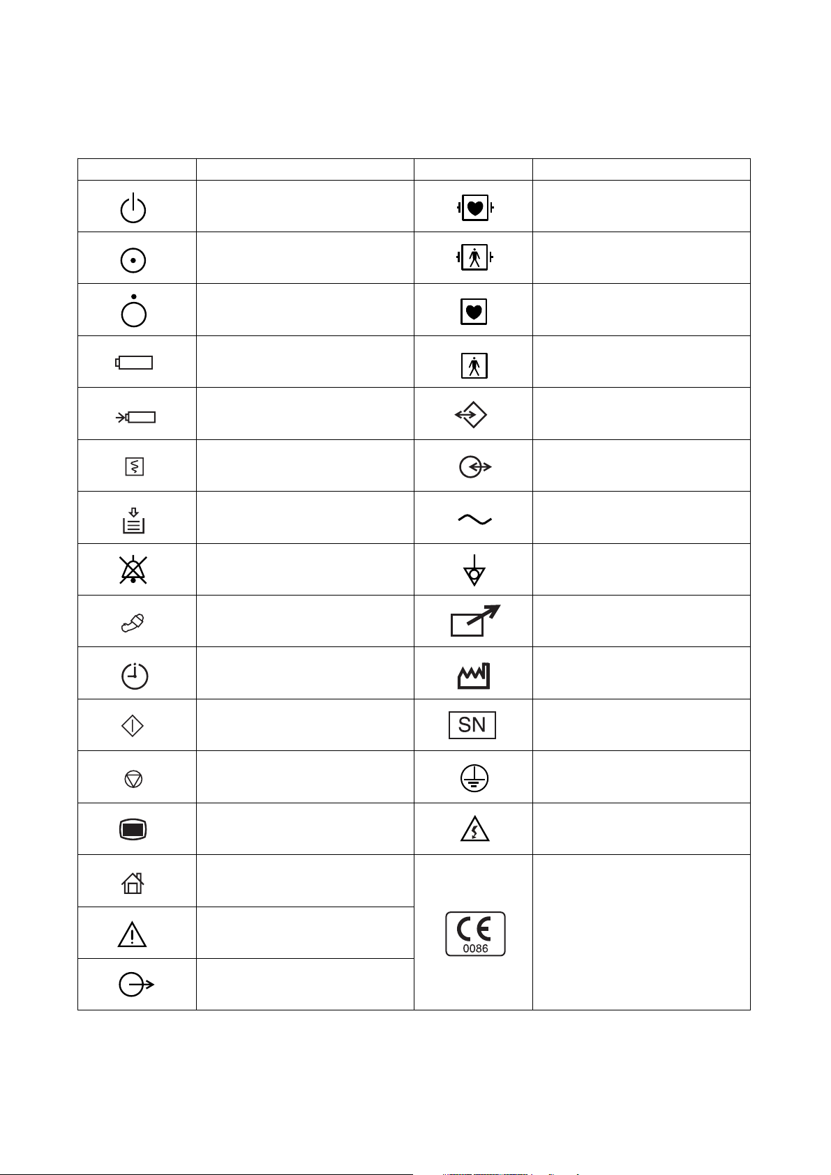
On panels
Symbol Description Symbol Description
Standby
“On” only for a part of instrument
“Off” only for a part of instrument Type CF applied part
Battery Type BF applied part
Battery charging Data input/output
Record start/stop Input/output terminal
Out of paper Alternating current
Alarm suspend Equipotential terminal
Defibrillation-proof type CF applied
part
Defibrillation-proof type BF applied
part
NIBP Remote terminal
NIBP interval Year of manufacture
NIBP start Serial number
NIBP stop Protective earth
Menu High voltage
Home (monitoring screen)
Attention, consult operator’s
manual
Output
The CE mark is a protected
conformity mark of the European
Community. The products herewith
comply with the requirements of the
Medical Device Directive
93/42/EEC.
Service Manual BSM-4100 v
Page 14
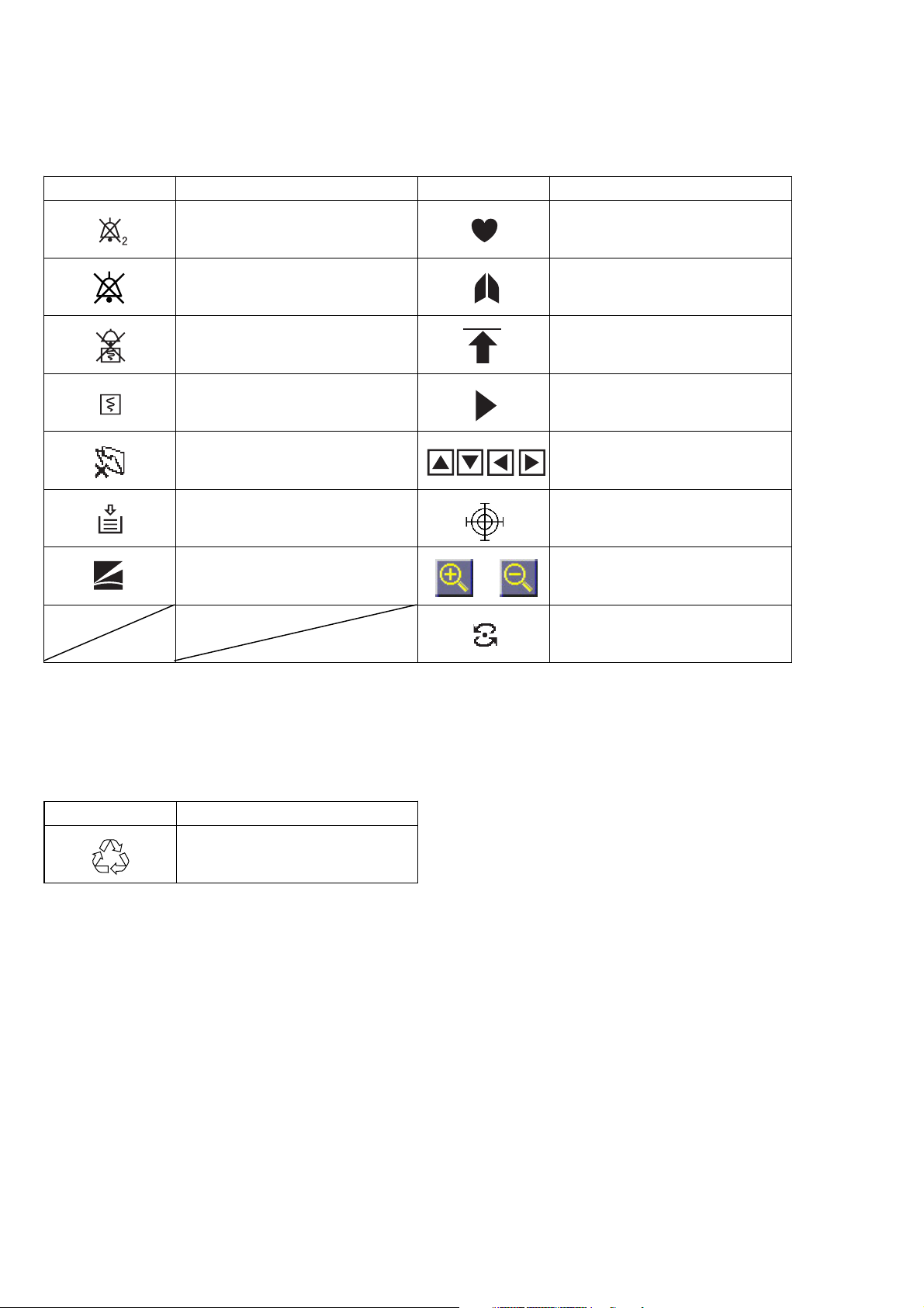
On screen
Symbol Description Symbol Description
Alarm suspend with remaining
minutes
Alarm off Respiration sync mark
Alarm recording off Value out of range
Recording Current setting
Paper magazine open Adjust setting
Out of paper Touch screen calibration mark
Function key Change scale
QRS/pulse sync mark
Network communicating
Others
Symbol Description
Recycle (On battery pack)
vi Service Manual BSM-4100
Page 15

Section 1 General
Introduction ......................................................................................................................... 1.1
General Information on Servicing ........................................................................................ 1.2
Service Policy, Service Parts and Patient Safety Checks ...................................................1.4
Service Policy ...........................................................................................................1.4
Service Parts ............................................................................................................ 1.4
Patient Safety Checks ..............................................................................................1.5
Composition ........................................................................................................................ 1.6
BSM-4101/4103/4111/4113 ....................................................................................... 1.6
BSM-4102/4104/4112/4114 ....................................................................................... 1.8
Specifications ................................................................................................................... 1.10
Display ..........................................................................................................1.10
Sound ............................................................................................................ 1.10
Alarm ............................................................................................................ 1.10
ECG ..............................................................................................................1.10
Respiration (Transthoracic impedance pneumography)..................................1.11
SpO2 on BSM-4101/4103/4111/4113 Monitors ..............................................1.11
SpO2 on BSM-4102/4104/4112/4114 Monitors ..............................................1.12
Non Invasive Blood pressure, NIBP .............................................................. 1.12
Invasive Blood Pressure, IBP .......................................................................1.13
Temperature .................................................................................................. 1.13
Cardiac Output, CO ....................................................................................... 1.13
Respiration (Thermistor method) ................................................................... 1.14
Inspired Oxygen Fractional Concentration, FiO2............................................ 1.14
Expired Carbon Dioxide Tension, CO2............................................................ 1.14
Trendgraph .................................................................................................... 1.15
Vital Signs List .............................................................................................. 1.15
Hemodynamics List (BSM-4103/4104/4113/4114 monitors only) .................. 1.15
Full Disclosure (QM-421P flash memory card required) ................................ 1.15
ECG/BP Output ............................................................................................ 1.15
Recorder (BSM-4101/4102/4103/4104 monitors only) ...................................1.15
External Output .............................................................................................1.16
Power Requirement ....................................................................................... 1.16
Environment .................................................................................................. 1.16
Dimensions and Weight (approximate) .......................................................... 1.16
Service Manual BSM-4100 1C.1
Page 16

Electromagnetic Compatibility....................................................................... 1.16
Safety Standard ............................................................................................ 1.16
Names and Function of Parts ............................................................................................ 1.18
Front Panel .............................................................................................................. 1.18
Socket Panel...........................................................................................................1.20
On the BSM-4101/4103/4111/4113 Monitors ................................................. 1.20
On the BSM-4102/4104/4112/4114 Monitors ................................................. 1.20
Using the Output Signal from the ECG/BP OUT Socket ...............................1.21
Using Multi-parameter Sockets for CO and CO2 Monitoring ........................... 1.21
Left Side Panel ........................................................................................................ 1.22
Right Side Panel...................................................................................................... 1.22
Storage and Transport ....................................................................................................... 1.23
Storage .................................................................................................................... 1.23
Transport .................................................................................................................1.23
Hard Keys and Soft Keys .................................................................................................. 1.24
Hard Keys ............................................................................................................... 1.24
Soft Keys ................................................................................................................ 1.24
Upgrading the System Software and Changing Language on the Screen .......................... 1.25
Procedure .....................................................................................................1.25
Board/Unit Connection Diagram ........................................................................................1.26
Block Diagram ................................................................................................................... 1.27
1C.2 Service Manual BSM-4100
Page 17

Introduction
1. GENERAL
This service manual provides useful information to qualified personnel to
understand, troubleshoot, service, maintain and repair the BSM-4100A/J/K Bedside
Monitor (referred to as “the instrument” in this service manual).
All replaceable parts or units of this instrument are clearly listed with exploded
illustrations to help you locate the parts quickly.
The “Maintenance” section in this service manual describes the maintenance that
should be performed by qualified service personnel. The “Maintenance” section in
the operator’s manual describes the maintenance that can be performed by the user.
The information in the operator’s manual is primarily for the user. However, it is
important for service personnel to thoroughly read the operator’s manual and
service manual before starting to troubleshoot, service, maintain or repair this
instrument. This is because service personnel need to understand the operation of
the instrument in order to effectively use the information in the service manual.
Service Manual BSM-4100 1.1
Page 18

1. GENERAL
General Information on Servicing
Note the following information when servicing the instrument.
Safety
••
• There is the possibility that the outside surface of the instrument,
••
such as the operation keys, could be contaminated by contagious
germs, so disinfect and clean the instrument before servicing it.
When servicing the instrument, wear rubber gloves to protect
yourself from infection.
••
• There is the possibility that when the lithium battery is broken, a
••
solvent or toxic substance inside the lithium battery could leak out.
If the solvent or toxic substance touches your skin or gets into your
eye or mouth, immediately wash it with a lot of water and see a
physician.
CAUTION
Liquid ingress
The instrument is not drip-proof, so do not install the instrument where
water or liquid can get into or fall on the instrument. If liquid
accidentally gets into the instrument or the instrument accidentally
drops into liquid, disassemble the instrument, clean it with clean water
and dry it completely. After reassembling, use the patient safety
checks and function/performance checks to verify that there is nothing
wrong. If there is something wrong with the instrument, contact your
Nihon Kohden representative for repair.
Environmental Safeguards
Depending on the local laws in your community, it may be illegal to
dispose of the lithium battery and CRT unit in the regular waste
collection. Check with your local officials for proper disposal
procedures.
Disinfection and cleaning
To disinfect the outside surface of the instrument, wipe it with a non-
abrasive cloth moistened with any of the disinfectants listed below. Do
not use any other disinfectants or ultraviolet rays to disinfect the
instrument.
- Chlorohexidine gluconate solution: 0.5%
- Benzethonium chloride solution: 0.2%
- Glutaraldehyde solution: 2.0%
- Benzalkonium chloride: 0.2%
- Hydrochloric alkyl diaminoethylglycine: 0.5%
1.2 Service Manual BSM-4100
Page 19

1. GENERAL
Transport
••
• Use the specified shipment container and packing material to
••
transport the instrument. If necessary, double pack the instrument.
Also, put the instrument into the shipment container after packing so
that the buffer material does not get inside the instrument.
••
• When transporting a board or unit of the instrument, be sure to use a
••
conductive bag. Never use an aluminum bag when transporting the
power board, power unit or board on which a lithium battery is
mounted. Also, never wrap the board or unit of the instrument with
styrene foam or a plastic bag which generates static electricity.
Handling the instrument
••
• Because the outside surface of the instrument is made of resin, it is
••
easily damaged. When handling the instrument, remove clutter from
around the instrument and be careful not to damage the instrument
or get it dirty.
••
• Because most of the boards in the instrument are multilayer boards
••
with surface mounted electrical devices (SMD), a special tool is
required when removing and soldering the electrical devices. To
avoid damaging other electrical components, do not remove and
solder SMD components yourself.
Measuring and Test Equipment
Maintain the accuracy of the measuring and test equipment by
checking and calibrating it according to the check and calibration
procedures.
Service Manual BSM-4100 1.3
Page 20

1. GENERAL
Service Policy, Service Parts and Patient Safety Checks
Service Policy Our technical service policy for this instrument is to replace the faulty unit, board
or part or damaged mechanical part with a new one. Do not perform electrical
device or component level repair of the multilayer board or unit. We do not support
component level repair outside the factory for the following reasons:
• Most of the boards are multilayer boards with surface mounted electrical
devices, so the mounting density of the board is too high.
• A special tool and special repair skill is required to repair the multilayer boards
with surface mounted electrical devices.
Disassemble the instrument or replace a board or unit in an environment where the
instrument is protected against static electricity.
As background knowledge for repair, pay special attention to the following:
• You can reduce the repair time by considering the problem before starting repair.
• You can clarify the source of most of the troubles using the information from the
diagnostic check function of the instrument. Refer to “Diagnostic Check “ of this
manual.
Service Parts
Refer to “Replaceable Parts List” of this manual for the service parts for technical
service that we provide.
NOTE
When ordering parts or accessories from your Nihon Kohden
representative, please quote the NK code number and part name which
is listed in this service manual, and the name or model of the unit in
which the required part is located. This will help us to promptly attend
to your needs. Always use parts and accessories recommended or
supplied by Nihon Kohden Corporation to assure maximum
performance from your instrument.
1.4 Service Manual BSM-4100
Page 21

1. GENERAL
Patient Safety Checks Periodic maintenance procedures and diagnostic check procedures are provided in
this manual to ensure that the instrument is operating in accordance with its design
and production specifications. To verify that the instrument is working in a safe
manner with regard to patient safety, patient safety checks should be performed on
the instrument before it is first installed, periodically after installation, and after any
repair is made on the instrument.
For patient safety checks, perform the following checks as described in the
International Electrotechnical Commission’s standard, IEC60601-1 (1988):
• Protective earth resistance check
• Earth leakage current check
• Enclosure leakage current check
• Patient leakage current check
• Withstanding voltage check
Service Manual BSM-4100 1.5
Page 22

1. GENERAL
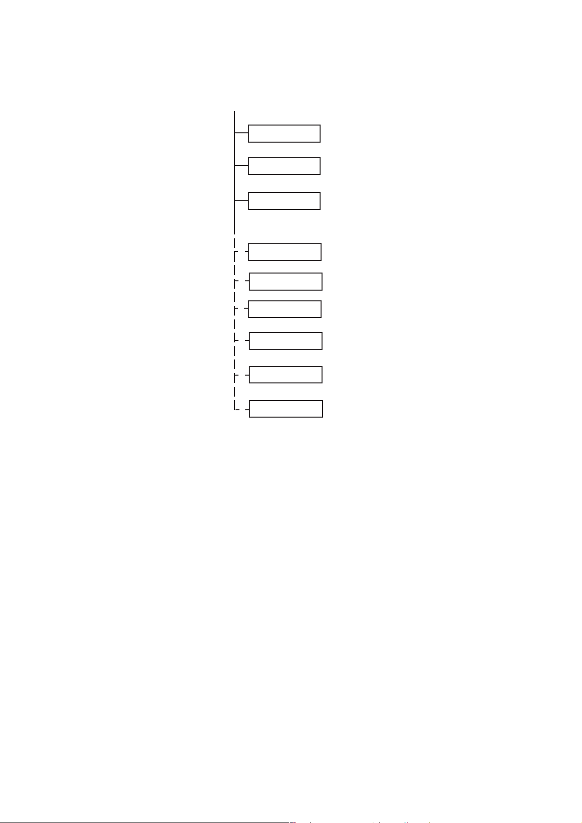
Composition
BSM-4101/4103/4111/4113
BSM-4101A
BSM-4101J
BSM-4101K
BSM-4111A
BSM-4111J
BSM-4111K
BSM-4103A
BSM-4103J
BSM-4103K
BSM-4113A
BSM-4113J
BSM-4113K
CD-225P
RG-921P
UR-3586
UR-3563
UR-3566
UR-3541
UR-35421
UR-35431
UR-3544
UR-3546
Chassis
Recorder Unit (BSM-4101/4103)
MAIN Board
DPU Board
Motherboard
Connection Board
Power SW Board
Operation Board
Function Dial Board
ECG RESP1 Board
UR-3547
UR-3548
UR-3561
UR-3564
UR-3567
UR-3557
UR-3558
UR-3559
UR-35591
SC-039R
ECG RESP2 Board
ECG RESP3 Board
NK SPO2 Board
NIBP Measure Board
NIBP Safety Board
MP1 Board
MP2 Board
MP3 Board (BSM-4103/4113)
MP3 Dummy Board (BSM-4101/4111)
Power Supply Block
1.6 Service Manual BSM-4100
Page 23

1. GENERAL
YS-024R0
YS-024R1
YS-024R3
QM-421P
ZB-800PA
ZB-800PG
ZB-800PK
QI-101P
QI-111P
Operation Panel
Input Panel (BSM-4101/4111)
Input Panel (BSM-4103/4113)
Flash Disk Card (Option)
Transmitter (Option)
Transmitter (Option)
Transmitter (Option)
Network Card (Option)
Network Printer Card (Option)
Service Manual BSM-4100 1.7
Page 24

1. GENERAL
BSM-4102/4104/4112/4114
BSM-4102A
BSM-4102J
BSM-4102K
BSM-4112A
BSM-4112J
BSM-4112K
BSM-4104A
BSM-4104J
BSM-4104K
BSM-4114A
BSM-4114J
BSM-4114K
CD-226P
RG-921P
UR-3586
UR-35631
UR-35661
UR-3541
UR-35421
UR-35431
UR-3544
UR-3546
Chassis
Recorder Unit (BSM-4102/4104)
MAIN Board
DPU Board
Motherboard
Connection Board
Power SW Board
Operation Board
Function Dial Board
ECG RESP1 Board
UR-3547
UR-3548
UR-35611
UR-3564
UR-3567
UR-3557
UR-3558
UR-35592
UR-35593
ECG RESP2 Board
ECG RESP3 Board
NL SPO2 Dummy Board
NIBP Measure Board
NIBP Safety Board
MP1 Board
MP2 Board
MP3 Board (BSM-4104/4114)
MP3 Dummy Board (BSM-4102/4112)
SC-039R
1.8 Service Manual BSM-4100
Power Supply Block
Page 25
1. GENERAL
YS-024R0
YS-024R2
YZ-024R4
QM-421P
ZB-800PA
ZB-800PG
ZB-800PK
QI-101P
QI-111P
Operation Panel
Input Panel (BSM-4102/4112)
Input Panel (BSM-4104/4114)
Flash Disk Card (Option)
Transmitter (Option)
Transmitter (Option)
Transmitter (Option)
Network Card (Option)
Network Printer Card (Option)
Service Manual BSM-4100 1.9
Page 26

1. GENERAL
Specifications
Display
Display size: 12.1 inch, TFT type LCD
Waveform display mode: Non-fade moving or non-fade fixed
Viewing area: 246 mm × 184.5 mm
Resolution: 800 × 600 dots
Maximum number of waveform trace: 13 traces (12 lead display)
Sweep speed: 25 mm/s, 50 mm/s (At compressed: 6.25 mm/s, Respiration low speed: 1.56 mm/s)
Sweep time: 7.4 s (at 25 mm/s sweep speed)
Waveform display color: 12
Numeric display color: 12
Waveform freeze: Provided
Display waveforms: ECG, respiration, IBP, SpO2 pulse wave, CO2 and CO thermodilution curve
Numerical data display: Heart rate, VPC rate, ST level, respiration rate, IBP (systolic, diastolic, mean),
NIBP (systolic, diastolic, mean), SpO2, pulse rate, temperature, CO, FiO2, ETCO
Synchronization mark: Heart rate sync mark, pulse rate sync mark, respiratory sync mark
2
Sound
Sound type: Alarm, synchronization, click
Alarm sound: 3 types
Synchronization sound: Pitch variable for IBP and SpO
2
Alarm
Alarm items: Upper/lower limits alarm, apnea alarm, arrhythmia alarm, connector disconnection
alarm, NOISE alarm, electrode off alarm, waveform detecting alarm, probe off
alarm, cuff/hose check alarm, sensor check alarm, low battery alarm, operating
environment alarm
Alarm types: Crisis (red blinking), Warning (yellow blinking), Advisory (yellow lighting),
Message
Alarm indication: Alarm indicator, highlighted message, alarm sound
Alarm suspend: Provided (for 1 or 2 min)
ECG
Electrode offset potential tolerance: ±500 mV
Input dynamic range: ± 5 mV
Internal noise: ≤20 µVp-p (Refer to input)
Common mode rejection ration: ≥90 dB
Input impedance ≥5 MΩ (at 10 Hz)
Input bias current: ≤100 nA
Heart rate count
Calculation method: Moving average/Instantaneous beat to beat (selectable)
Counting range: 0, 12 to 300 beats/min (±2 beats/min)
Arrhythmia analysis
Analysis method: Template matching method
Number of channels: 1 channel
VPC counting rate: 0 to 99 VPCs/min
1.10 Service Manual BSM-4100
Page 27

Arrhythmia message: ASYSTOLE, VT, VF, VPC RUN, COUPLET, EARLY VPC, BIGEMINY, FREQ
VPC, TACHYCARDIA, BRADYCARDIA, NOISE, Electrode OFF, LEARNING
Arrhythmia recall:
Number of recall files: 16
Storage time per file: 8 s
ST level measurement:
Number of measurement channels:3-electrodes: 1 ch
6-electrodes: 8 ch
10-electrodes: 12 ch
Measuring range: ±2.5 mV
Pacemaker pulse rejection capability: 0.1 to 2 ms, ±2 to 700 mV
ANSI/AAMI EC 13-1992 compatible
Pacing pulse detection ON/OFF
Defibrillation-proof: ECG input protected against 400 J
IEC 60601-2-27 17.101 compatible
ESU interference filter: Provided
AC hum filter: OFF: 150 ±10 Hz (> −3 dB)
ON: 23 ±3 Hz (> −3 dB)
≤ −16 dB (50 Hz or 60 Hz)
Lead:
3-electrode cable: I, II, III
6-electrode cable: I, II, III, aVR, aVL, aVF, 2 from V1 to V6
10-electrode cable: I, II, III, aVR, aVL, aVF, V1 to V6
Waveform display:
Display sensitivity: 10 mm/mV ±5% (at ×1 sensitivity)
Sensitivity control: ×1/4, ×1/2, ×1, ×2, ×4, or AUTO
Auto positioning: Available
Pacing spike display: Available
Heart rate display update cycle: Every 3 s or when alarm is generated
Alarm items:
Upper limit range: 20 to 300 beats/min in 5 beats/min steps, OFF
Lower limit range: OFF, 15 to 295 beats/min in 5 beats/min steps
Alarm items: TACHYCARDIA, BRADYCARDIA, ASYSTOLE
1. GENERAL
Respiration (Transthoracic impedance pneumography)
Measuring impedance available range: 0 to 2 kΩ
Internal noise: ≤0.2 Ω (Refer to input)
Excitor current: 30 ±10 µArms at 31.25 kHz
Frequency response: 0.1 to 3.2 Hz ±1 Hz (−3 dB)
Respiration counter counting range: 0 to 150 breaths/min
Defibrillation proof: Respiration input protected against 400 J discharge
Waveform display:
Display sensitivity: 10 mm/Ω ±25% (at ×1 sensitivity)
Sensitivity control: ×1/4, ×1/2, ×1, ×2, ×4
Respiration rate display update cycle: Every 3 s or when alarm is generated
Alarm:
Upper limit range: 2 to 150 breaths/min in 2 breaths/min steps, OFF
Lower limit range: OFF, 0 to 148 breaths/min in 2 steps
Apnea time: OFF, 5 to 40 s in 5 s steps
Service Manual BSM-4100 1.11
Page 28

1. GENERAL
SpO
on BSM-4101/4103/4111/4113 Monitors
2
Measuring range: 50 to 100%
SpO2 accuracy: ±2 digits (80% ≤ SpO2 ≤ 100%)
±3 digits (50% ≤ SpO2 < 80%)
SpO2 display:
Pulse rate display update cycle: Every 3 s or when alarm is generated
Sync tone modulation: Change in 20 steps at 81 to 100% SpO
Waveform sensitivity: ×1/8, ×1/4, ×1/2, ×1, ×2, ×4, ×8
Alarm:
Upper limit range: 51 to 100% SpO2 in 1% SpO2 steps, OFF
Lower limit range: OFF, 50 to 99% SpO2 in 1% SpO2 steps
SpO2 on BSM-4102/4104/4112/4114 Monitors
Measuring range: 1 to 100%
SpO2 accuracy: DS-100A: ±3% SpO
OXIBAND A/N: ±3% SpO
OXIBAND P/I: ±3% SpO
RS-10: ±3.5% SpO
D-YS: ±3% SpO
D-YSE: ±3.5% SpO
D-YSPD: ±3.5% SpO
D-25/D-25L: ±2% SpO
N-25: ±2% SpO
I-20: ±2% SpO
D-20: ±2% SpO
R-15: ±3.5% SpO
OXICLIQ I: ±2.5% SpO
OXICLIQ P: ±2.5% SpO
OXICLIQ A: ±2.5% SpO
OXICLIQ N: ±2.5% SpO
OXI1-2-3 A/N: ±2.5% SpO
OXI1-2-3 P/I: ±2.5% SpO
2
2
2
2
2
2
2
2
2
2
2
2
2
2
2
2
2
2
SpO2 display:
Pulse rate display update cycle: Every 3 s or when alarm is generated
Sync tone modulation: Change in 20 steps at 81 to 100% SpO
Waveform sensitivity: ×1/8, ×1/4, ×1/2, ×1, ×2, ×4, ×8
Alarm:
Upper limit range: 51 to 100% SpO2 in 1% SpO2 steps, OFF
Lower limit range: OFF, 50 to 99% SpO2 in 1% SpO2 steps
2
2
Non Invasive Blood pressure, NIBP
Measuring method: Oscillometric
Cuff pressure display range: 0 to 300 mmHg
Accuracy: ±3 mmHg (0 mmHg ≤ NIBP ≤ 200 mmHg)
±4 mmHg (200 mmHg ≤ NIBP ≤ 300 mmHg)
Safety:
Maximum pressurization value cuff inflation limiter: Adult 300 to 330 mmHg
Neonates 150 to 165 mmHg
Cull inflation time limiter: Adult 161 to 165 s
Neonates 81 to 84 s
1.12 Service Manual BSM-4100
Page 29

1. GENERAL
Measurement mode: Manual
Continuous
Periodic: 2, 2.5, 5, 10, 15, 30 min, 1, 2, 4, 8 hr interval
NIBP data display update cycle: Updated every measurement
Measurement end sound: Generated when measurement ends
Alarm:
Upper limit range: 15 to 260 mmHg in 5 mmHg steps, OFF
Lower limit range: OFF, 10 to 255 mmHg in 5 mmHg steps
Invasive Blood Pressure, IBP
Measuring range: −50 to 300 mmHg
Measuring accuracy: ±1 mmHg ±1 digit (−50 mmHg ≤ IBP < 100 mmHg)
±1% ±1 digit (100 mmHg ≤ IBP ≤ 300 mmHg)
Auto zero balancing range: ±200 mmHg
Auto zero balancing accuracy: ±1 mmHg
Transducer sensitivity: 50 µV/V/10 mmHg
Pulse rate counting range: 0, 12 to 300 beats/min
Pulse rate counting accuracy: ±2 beats/min
Noise: Within ±1 mmHg
Temperature zero drift: ±0.1 mmHg/1°C
Frequency response: DC to 20 Hz ±3Hz
Display update cycle: Every 3 or when alarm is generated
BP sync sound: Provided, systolic value 20 to 120 mmHg, changes in 20 steps every 5 mmHg
Alarm:
Upper limit range: 2 to 300 mmHg in 2 mmHg steps, OFF
Lower limit range: OFF, 0 to 298 mmHg steps in 2 mmHg steps
Temperature
Measuring range: 0 to 45°C
Measuring accuracy: ±0.1°C (25°C ≤ Temp ≤ 45°C)
±0.2°C ( 0°C ≤ Temp < 25°C)
Temperature drift: within ±0.005°C /°C
Temperature range:
Display range: 0°C to 45°C (32 to 115°F)
Display update cycle: Every 3 s
Alarm:
Upper limit range: 0.1 to 45°C (32 to 113°F) in 0.1°C (1°F) steps, OFF
Lower limit range: OFF, 0 to 44.9°C (31 to 112°F) in 0.1°C (1°F) steps
Cardiac Output, CO
Measuring method: Thermodilution method
Measuring range:
Injectate temperature (Ti): 0°C to 27°C
Blood temperature (Tb): 15°C to 45°C
Thermodilution curve (delta Tb): 0°C to 2.5°C
Cardiac output (CO): 0.1 to 20 L/min
Measuring accuracy:
Ti: ±0.2°C
Tb 25 to 45°C: ±0.1°C
Service Manual BSM-4100 1.13
Page 30

1. GENERAL
Tb 15 to 25°C: ±0.2°C
CO: ±5%
Temperature drift:
Ti: ±0.005°C /°C
Tb: ±0.005°C /°C
Frequency response (delta Tb): DC to 3 Hz (−3 dB)
Injectate volume range: 3, 5, 10 mL (7F)
1, 2, 3, 4, 5 mL (5F)
Respiration (Thermistor method)
Respiration rate counting range: 0 to 150 breaths/min
Apnea, 5 to 40 s
Accuracy: ±1 breath/min
Noise: Within 2.5 Ω (Refer to input)
Frequency response: 0.1 to 3 Hz (−3 dB)
Waveform display
Display sensitivity: 10 mm/100 Ω ±10% (at ×1 sensitivity)
Sensitivity control: ×1/4, ×1/2, ×1, ×2, ×4
Respiration rate display update cycle: Every 3 or when alarm is generated
Alarm:
Upper limit range: 2 to 150 breaths/min in 2 breaths/min steps, OFF
Lower limit range: OFF, 0 to 148 breaths/min in 2 breaths/min
Apnea time: OFF, 5 to 40 s in 5 s steps
Inspired Oxygen Fractional Concentration, FiO
Measuring range: 10 to 100% O
2
2
Accuracy: ±3% full scale (When calibrated at 21% O2)
±2% full scale (When calibrated at 100% O2)
Temperature drift: ±0.12% O2/°C
FiO2 display update cycle: Every 3 s or when alarm is generated
Alarm:
Upper limit range: 19 to 100% in 1% steps, OFF
Upper limit range: OFF, 18 to 99% in 1% steps
Expired Carbon Dioxide Tension, CO
2
Measuring method: Mainstream (TG-900P)
Measuring range:
TG-900P: 0 to 99 mmHg
Warm-up time: 5 s (min)
Response time
TG-900P: 200 ms (typical) for steps from 10 to 90%
Detectable respiration rate
Mainstream: 3 to 60 breaths/min
Measuring accuracy:
TG-900P: ±4 mmHg (0 ≤ CO2 ≤ 40 mmHg)
±10% reading (40 < CO2 ≤ 76 mmHg)
(When 1 atmospheric pressure, air inspiration, no condensation)
CO2 value display update cycle: Every 3 s or when alarm is generated
Alarm:
Upper limit range: 2 to 99 mmHg in 1 mmHg in 1 steps, OFF
1.14 Service Manual BSM-4100
Page 31

1. GENERAL
Lower limit range: OFF, 1 to 98 mmHg in 1 steps
Apnea time: OFF, 5 to 40 s
Trendgraph
Trend parameters: Heart rate (or pulse rate), respiration rate, VPC rate, ST level, EVENT, apnea
(time), apnea (frequency), SpO
diastolic and mean), temperature, CO2 and FiO
, NIBP (systolic, diastolic and mean), IBP (systolic,
2
2
Trend times: 1, 2, 4, 8, and 24 h
Vital Signs List
Parameters: Heart rate (or pulse rate), VPC rate, ST level, NIBP (systolic, diastolic and mean),
SpO2, IBP (systolic, diastolic and mean), respiration rate, temperature, CO2 and
FiO
2
Number of files in list: Periodic vital signs list: 120
Entries in vital signs list at NIBP measurement: 120
List interval: Periodic vital signs list: 1, 5, 15, 30 or 60 minutes
Vital signs list at NIBP measurement: at NIBP measurement
Hemodynamics List (BSM-4103/4104/4113/4114 monitors only)
Number of files: 8
Full Disclosure (QM-421P flash memory card required)
Storage time: 48 hours
ECG/BP Output
Output impedance
ECG: ≤100 Ω
BP: ≤100 Ω
Output-waveform
ECG: ±5.0 V (at 1 mV/V sensitivity)
BP: −0.5 to +3.0 V(at 100 mmHg/V sensitivity)
Heart rate Trigger: Open collector output
Frequency response
ECG: 0.05 to 23 Hz (>−3 dB)
(Differ in ECG display mode setting)
BP: ≥DC to 20 Hz (>−3 dB)
Sensitivity accuracy
ECG: ±5%
BP: ±5% (Exclude offset)
Delay
ECG: Hum filter off: approx. 2 ms
Hum filter on: approx. 10 ms
BP: 20 Hz filter: approx. 30 to 35 ms max
HT: approx. 32 to 64 ms max
Recorder (BSM-4101/4102/4103/4104 monitors only)
Recording method: Thermal array recording
Number of channels: 3 traces (maximum)
Recording width: ≥48 mm
Service Manual BSM-4100 1.15
Page 32

1. GENERAL
Paper speed: 25, 50 mm/s
Recording paper: FQW-50-3-100
External Output
ZB-800PA/PG/PK: Provided
External monitor: Provided
Power Requirement
Line voltage:
BSM-4100A: AC 117 V ±10%
BSM-4100J: AC 100 to 127 V ±10%
BSM-4100K: AC 220 to 240 V ± 10%
DC (NKB-101): 10.8 to 16.0 ±5%
Line frequency:
BSM-4100A: 60 Hz ±2%
BSM-4100J/K: 50 or 60 Hz ±2%
Power consumption: AC: 80 VA maximum
DC: 50 W maximum
Environment
Operating environment
Temperature: 10 to 40°C
Humidity: 30 to 90% RH (0 to 40°C, non-condensing)
Atmospheric pressure: 68 to 106 kPa
Storage environment
Temperature: −20 to +65°C
−15 to +55°C (Recording paper)
Humidity: 15 to 95% RH (0 to 40°C, non-condensing)
Atmospheric pressure: 68 to 106 kPa
Dimensions and Weight (approximate)
Dimensions: 339 mm W × 375 mm H ×159 mm D
Weight: 9 kg (excluding battery)
Electromagnetic Compatibility
IEC60601-1-2 (1993) – Collateral Standard: Electromagnetic compatibility – Requirement and tests
Emissions: CISPR11 Group 1, Class B
Safety Standard
Safety standard: IEC 60601-1 (1988) Amendment 1 (1991), Amendment 2 (1995)
IEC 6060-2-27 (1994) - Particular requirements for the safety of
electrocardiographic monitoring
IEC 60601-2-25 (1993)/NS 1231 (1995) - Particular requirements for the safety of
electrocardiographic
IEC 60601-2-30 (1995) - Particular requirements for the safety of automatic
cycling in direct blood pressure monitoring equipment
According to the type of protection against electrical shock:
CLASS I EQUIPMENT (AC Powered)
Internally Powered EQUIPMENT (BATTERY Powered)
1.16 Service Manual BSM-4100
Page 33

1. GENERAL
According to the degree of protection against electrical shock
ECG, Respiration (impedance), IBP: Defibrillator-proof type CF applied part
Temperature, CO: CF applied part
NIBP: Defibrillator-proof type BF applied part
SpO
, Respiration (thermistor), CO2, FiO2: BF applied part
2
According to the degree of protection against harmful ingress of water:
IPX0 (ordinary EQUIPMENT)
According to the degree of safety of application in the presence of FLAMMABLE ANAESTHETIC MIXTURE WITH AIR,
OR WITH OXYGEN OR NITROUS OXIDE:
Equipment not suitable for use in the presence of FLAMMABLE ANAESTHETIC
MIXTURE WITH AIR, OR WITH OXYGEN OR NITROUS OXIDE
According to the mode of operation: CONTINUOUS OPERATION
Service Manual BSM-4100 1.17
Page 34

1. GENERAL
Names and Function of Parts
Front Panel
12
13
1
2
3
SILENCE
ALARMS
4
NIBP
INTERVAL
START/STOP
MENU
HOME
5
6
7
8
9
14 15
16
17 18
19
11
10
20
1.18 Service Manual BSM-4100
Page 35

1. GENERAL
No. Name Description
1 Alarm indicator
2 Handle For carrying the instrument.
3 SILENCE ALARMS key Silences the alarm sound.
4 Function dial 1 and 2
5 NIBP INTERVAL key Selects NIBP measurement mode. Pressing this key changes the mode.
6 NIBP START/STOP key
7 MENU key Displays the MENU window.
Red or orange lamp blinks according to the alarm settings. Green lamp blinks
in synchronization with the patient’s QRS.
Used for setting alarm limits and scrolling list or trendgraphs. When the
function dial lamp lights, the function dial is available.
Starts NIBP measurement in selected mode. Pressing the key during
measurement stops measurement.
8 HOME key Closes any opened window and displays the monitoring screen.
9 Socket panel Refer to the “Socket Panel” section.
10 Paper magazine Holds recording paper. (BSM-4101/4102/4103/4104 only)
11 Paper window
12 Paper magazine release lever
13 Touch screen
14 Power switch
15 Power lamp Lights when the instrument power is turned on.
16 AC power lamp
17 Battery power lamp Lights when operating on the battery power.
18 Battery charging lamp Lights or slowly blinks when charging.
19 Record key Press to start or stop recording.
20 Out of paper lamp
For checking the amount of recording paper.
(BSM-4101/4102/4103/4104 only)
Pull up the lever to open the paper magazine.
(BSM-4101/4102/4103/4104 only)
Displays monitoring data. Touching a key or data on the screen changes
displaying screen and settings.
Press and hold for more than one second to turn the instrument power on or
off.
Lights when the power cord is connected between the AC SOURCE socket
and AC outlet.
Blinks when out of paper. Lights when paper magazine is open.
(BSM-4101/4102/4103/4104 only)
Service Manual BSM-4100 1.19
Page 36

1. GENERAL
Socket Panel
On the BSM-4101/4103/4111/4113 Monitors
Refer to Warning and Caution in the
"General Safety Information" in the
SpO2 socket
Connects to the SpO2 connection cord.
operator's manual.
ECG/RESP socket
Connects to the ECG
connection cord.
Multi-parameter sockets
Connect to the connection cord of the
parameter to be monitored (IBP,
temperature, CO, CO2, FiO2 or
Refer to Warning and
Note on the next page.
NIBP socket
Connects to the air hose.
Refer to Warning and Caution in the
Refer to Warning and Note on the next page.
respiration by thermistor method).
The type of parameter is automatically
recognized. BSM-4101/4111 monitors
have two sockets and BSM-4103/4113
monitors have three sockets.
"General Safety Information" in the
operator's manual.
ECG/BP OUT socket
Outputs 100 mmHg/V IBP waveform of the IBP connected to the multi-parameter 1 socket,
1 mV/V ECG waveform and heart rate trigger by using the YJ-910P or YJ-920P ECG/BP output cable.
These analog signals can be used as the synchronization signal for other equipment, such as IABP or
defibrillator. Refer to the warning on the next page.
On the BSM-4102/4104/4112/4114 Monitors
Multi-parameter sockets
Connect to the connection cord of the parameter to be
NIBP socket
Connects to the air hose.
Refer to Warning and Caution in the
“General Safety Information” in the
monitored (IBP, temperature, CO, CO2, FiO2 or respiration by
thermistor method). The type of parameter is automatically
recognized. BSM-4102/4112 monitors have two sockets and
BSM-4104/4114 monitors have three sockets.
operator’s manual.
ECG/RESP socket
Connects to the ECG
connection cord.
Refer to Warning and Note
on the next page.
NELLCOR
TM
OxiMax
Refer to Warning and Caution in the
“General Safety Information” in the
operator’s manual.
ECG/BP OUT socket
Outputs 100 mmHg/V IBP waveform of the IBP connected to the multi-parameter 1
socket, 1 mV/V ECG waveform and heart rate trigger by using the YJ-910P or YJ-920P
ECG/BP output cable. These analog signals can be used as the synchronization signal for
other equipment, such as IABP or defibrillator. Refer to the warning on the next page.
SpO2 socket
Connects to the SpO
2
connection cord.
Refer to Warning and Caution in
the “General Safety
Information” in the operator’s
manual.
When “NELLCOR OxiMax” is
indicated, MP506 SpO2 module
is built in.
Refer to Warning and Note on
the next page.
1.20 Service Manual BSM-4100
Page 37

1. GENERAL
Using the Output Signal from the ECG/BP OUT Socket
WARNING
When using the output signal from the instrument as the synchronization signal for other equipment such
as IABP (intra-aortic balloon pump) or defibrillator:
••
• Set the timing of the other equipment by checking the waveform on the monitoring screen.
••
••
• Check the condition of the bedside monitor at all times. The output signal may become unstable.
••
••
• Check that the delay time of the output signal (heart rate trigger 64 ms maximum) is within the range of
••
the connected equipment.
••
• Do not use the heart rate trigger as the synchronization signal for defibrillator.
••
NOTE
The output signal from the ECG/BP OUT socket may become unstable in the following conditions.
••
• Electrode is dry or detached.
••
••
• Electrode lead is damaged or disconnected from the electrode.
••
••
• Electrode lead is pulled.
••
••
• AC interference or EMG noise superimposed.
••
••
• Air bubbles or blood clog in the circuit for monitoring IBP.
••
••
• Cord or cable is disconnected or damaged.
••
The Delay Time of the Output Signal
Output Signal
ECG
IBP
Heart rate trigger 32 to 64 ms
Using Multi-parameter Sockets for CO and CO
Filter Setting
Hum filter OFF
Hum filter ON
Filter 20 Hz
Delay Time
2 ms
10 ms
30 to 35 ms
Monitoring
2
WARNING
••
• When performing defibrillation during CO monitoring, never touch the CO connection cord. Otherwise
••
the discharged energy may cause serious electrical burn, shock or other injury.
••
• When performing defibrillation during CO2 monitoring with the TG-900P CO2 sensor kit, remove the
••
sensor from the patient. When the sensor cannot be removed, do not touch the sensor cable because
the discharged energy may cause serious electrical burn, shock or other injury.
NOTE
••
• CO monitoring using the multi-parameter socket does not comply with the Defibrillator proof type CF.
••
••
• CO2 monitoring using the multi-parameter socket does not comply with the Defibrillator proof type BF.
••
Service Manual BSM-4100 1.21
Page 38

1. GENERAL
PC card eject button
PC card lamp
PC card slot
For an optional QI-101P network card.
AUX socket
For connecting a display monitor with a
YS-072P5 connection cable.
REMOTE socket
Not available.
Equipotential grounding terminal
For an equipotential grounding lead.
AC SOURCE power cord socket
For the AC power cord.
Fuse holder
Refer to "Connecting the Power
Cord and Grounding the Monitor"
in Section 2.
Left Side Panel
CAUTION
••
• Use only the Nihon Kohden card.
••
••
• Do not press the PC card eject button while
••
the PC card lamp is lit. This may damage the
PC card data and interrupt network
communication.
CAUTION
Connect only the specified instrument to the socket marked with by following the specified procedure.
Otherwise, electrical leakage current may harm the patient and operator.
Right Side Panel
Connect only the ZB-800P transmitter to the ZB
socket by following the specified procedure.
Otherwise, electrical leakage current may harm the
patient and operator.
CAUTION
ZB socket
For the ZB-800P transmitter.
1.22 Service Manual BSM-4100
Battery pack holder
Page 39

Storage and Transport
Follow these procedures when storing or transporting the instrument.
1. GENERAL
Storage
Transport
Before storing the instrument for a long time, perform the following steps:
1. Disconnect the power cord from the instrument.
2. Cover the instrument with a dust cover.
3. If possible, store the instrument in its original shipping container.
4. Make sure the storage place meets the following storage conditions for the
duration of the storage.
Storage temperature: −20 to 60°C (−4 to 130°F)
Storage humidity: 15 to 95% RH, non-condensing
To transport the instrument, perform the following steps:
1. Disconnect the power cord from the instrument.
2. Cover the instrument with a dust cover.
3. If possible, transport the instrument in its original shipping container.
Service Manual BSM-4100 1.23
Page 40

1. GENERAL
Hard Keys and Soft Keys
Hard Keys
Soft Keys
The instrument has six hard keys: SILENCE ALARMS, NIBP INTERVAL, NIBP
START/STOP, MENU, HOME and RECORD.
These keys always have the same functions, regardless of the screen display.
In this manual, hard keys are indicated by CAPITAL LETTERS.
When the MENU key is pressed or the screen is touched, the screen displays
several keys which have different functions depending on the screen display. For
example, when the HR numeric display is touched, the ECG setting screen appears
and several keys such as VITAL ALARM, ARRHYTH ALARM, OTHER
SETTING, etc are displayed.
In this manual, soft keys are indicated by quotation marks (for example, the
“VITAL ALARM” key).
1.24 Service Manual BSM-4100
Page 41

1. GENERAL
Upgrading the System Software and Changing Language on the
Screen
CAUTION
Upgrading the system software and changing the language on screen
erases all system and monitoring settings. Write down these settings
so they can be re-entered after the software upgrade.
The instrument uses a program card for upgrading its system software and
changing the screen language. When the instrument detects that a program card is
inserted into its PC card slot during the booting stage after it is turned on, it checks
the program card for a system program or language. If the program card contains a
newer version of the system program or language, the instrument automatically
replaces its current system program or language information with the new one. If
the program card contains a system program whose version number is the same or
older than the one in the instrument, you have the option to replace or keep the
current system program. If the program card does not contain a system program,
the instrument continues the boot-up process.
In the system software upgrading or language changing process, the instrument
first deletes the old system software or language stored in its system ROM. Then it
checks whether the data in the system ROM is completely deleted. When the data is
completely deleted, it copies the new version of the system program or language
information from the program card to the system ROM and then checks the copy
process. After the data is successfully copied, it performs the self-check programs
to check the equipment.
Procedure
1. Write down the System Setup settings and monitoring settings of the
instrument.
2. Insert the program card into the PC card slot on the left side panel of the
instrument.
3. Turn on the instrument. The instrument performs the upgrading process and
self-check programs. The DIAGNOSTIC CHECK screen appears.
4. Confirm that the new system software version number appears.
Service Manual BSM-4100 1.25
Page 42

1. GENERAL
Board/Unit Connection Diagram
Power
Supply
Unit
AUX Socket
CN105
CN121 to CN123
Recorder Unit***
RG-921P
CD-225P/226P
12.1-inch
TFT LCD
Card Slot
Network Card QI-101P,
Network Printer Card QI-111P
or Program Card
Flash Disk
Card
QM-421P
Card Slot
Inverter
CN108
CN102
Touch
screen
Connection Board
UR-3541
DPU Board
UR-3563/
35631
MAIN Board
UR-3586
CN006
CN103
NIBP Measure Board
UR-3564
Speaker
Alarm
Indicator
Power SW
Board
UR-35421
Operation
Board
UR-35431
Function Dial
Board
UR-3544
***BSM-4101/4102/4103/4104 only
CD-225P/226P
Mother-
board
UR-3566/
35661
NIBP Safety
Board
ZB-800P
board)
2
*BSM-4101/4103/4111/4113 (NK SpO
UR-3567
dummy board)
2
ECG RESP2
Board
UR-3547
ECG RESP1
Board
UR-3546
BSM-4102/4104/4112/4114 (Nellcor SpO
ECG/BP
Out
ECG RESP3
Board
UR-3548
NIBP
SpO2 Board*
UR-3561/35611
SpO2
MP1 Board
UR-3557
MP1
MP2 Board
UR-3558
MP2
MP3 Board**
MP4 Board
UR-3559/35592
MP3
**BSM-4103/4104/4113/4114 only
ECG/RESP
1.26 Service Manual BSM-4100
Page 43

Block Diagram
1. GENERAL
DPU Board
CPU
Battery
Lithium
System RAM
512 k x 16 SRAM
System ROM
256 k x 16 Flash
20 MHz
MC68SEC000
Common RAM
256 k x 16 SRAM
Clock
Real-time
Power
Supply
Analog
Converter
DC to DC
BUS
V
Interrup
/DTACK
/Reset
DPU Bus = Address Bus, Data Bus, Control signal Bus
Bus
Buffer
Bus
Buffer
TxD
Reset
Interface
ZB-800P
+8 V
TxD
Reset
SYLPH
DPU ASIC
(A to D Control)
WDT
/Reset
IC
Reset
+3.3 V
/Reset
RxD
RxD
ZB Socket
NIBP Measure
NIBP Safety
Serial communication
Motherboard
Supply
Transfer
A to D Converters on
snd (7:0)
Floating
Power
Floating
BUS
V
MP3
MP1
SpO2
ECG
RESP3
ECG
BUS
V
12 lead
ECG RESP1
and Resp
Analog ECG
Speaker
Microcontroller
from Power Supply
ECG RESP3 and MP1 boards
ECG
RESP2
1.5 W
Generator
FM Sound
Multi 3
Multi 2
Multi 1
SpO2
NIBP
ECG Socket
BUS
V
LED
BUS
V
Interface
Alarm Indicator
Analog Boards
Driver
Alarm
Board
Indicator
Power
Switch
Power SW Board
Backup RAM
32 k x 8 EEPROM
Super
Capacitor
Boot ROM
64 k x 16 EPROM
Host CPU
System RAM
System ROM
MC68SEC000
MAIN Board
lines
Chip select
512 k x 16 SRAM
1 M x 16 Flash
Main System Bus = Address Bus, Data Bus, Control signal Bus
20 MHz
20 MHz
Local CPU
MC68SEC000
512 k x 16
Flash ROM
RACOON
Recorder ASIC
Rec Bus = Address, Data, Control signal
SRAM
256 k x 16
Interrupt
/DTACK
/Reset
/Reset
(Recorder Control)
+5 V
Interface
Recorder
Buffer
+5 V
+24 V
Unit
Recorder
/Reset
/Reset
Interface
ATA Card
PCMCIA Card
+3.3 V
QM-421P
QI-101P
ACORN
Main ASIC
Interface
RxD
Remote
TxD
RxD
AUX
Socket
(CPU Peripheral)
/Reset
Reset
TxD
WDT
IC
From
CG RAM-1
+24 V
+3.3 V
DC to DC
BUS
V
Analog RGB I/F
CG RAM-2
2 M x 32 SDRAM
2 M x 32 SDRAM
IBIS
Graphic ASIC
(LCD Control)
+5 V
+3.3 V
Converter
Converter
DC to DC
Unit
Power Supply
C RAM
512 k x 8 SRAM
R (5:0), CLK,
G (5:0), H_Sync
B (5:0), V_Sync
IC
Reset
3.3 V_PS
SW
AC/Battery
+15 V_PS
+5 V
Reset at
Power Fail
Controller
Touch screen
B
LVDS
G
R
Analog RGB
8-bit
Power Supply
Microcontroller
Battery
Interface
Option
Battery Pack
BUS
V
Interface
Interface
XTAL
2 MHz
Buzzer
BUS
V
Board
Operation
Connection Board
To
AUX Socket
to
LED Driver
Driver
Buzzer
Function
Inverter
1700 V AC max
800 x 600
TFT LCD
Dial Board
Touch
Screen
Service Manual BSM-4100 1.27
Page 44

Section 2 Troubleshooting
General ................................................................................................................................ 2.1
Power-Related Problems .....................................................................................................2.2
Display Problems ................................................................................................................ 2.3
Sound Problems ..................................................................................................................2.4
Key Operation Problems ...................................................................................................... 2.4
Recording Problems ............................................................................................................2.5
ECG and Respiration by Impedance Method Problems .......................................................2.6
SpO2 Problems ....................................................................................................................2.7
Non-invasive Blood Pressure Problems ..............................................................................2.8
Other Vital Sign Input Problems ..........................................................................................2.9
ECG/BP Output Problems ................................................................................................. 2.12
Option Problems ...............................................................................................................2.13
Service Manual BSM-4100 2C.1
Page 45

General
2. TROUBLESHOOTING
Use the troubleshooting tables to locate, identify, and solve a problem in the
instrument. The problems are divided into general problem areas. Each category
has its own troubleshooting table for fast and easy troubleshooting.
• Power-related Problems
• Display Problems
• Sound Problems
• Key Function Problems
• Recording Problems
• ECG and Respiration by Impedance Method Problems
• SpO
Problems
2
• NIBP Problems
• Other Vital Sign Input Problems
• ECG/BP Output Problems
• Option Problems
If these sections do not solve the problem, contact your Nihon Kohden
representative.
NOTE
Before contacting your Nihon Kohden representative for technical
support, please provide additional detailed information on the problem.
This will allow your Nihon Kohden representative to provide you with
the best support.
How to use the troubleshooting table
1. Determine which troubleshooting table to use.
2. In the “Problem” column, find the trouble item that matches the problem.
3. Do the action recommended in the “Action” column.
4. If the problem is not solved, do the action for the next possible cause or
criteria.
5. If none of the actions solve the problem, contact your Nihon Kohden
representative.
Service Manual BSM-4100 2.1
Page 46
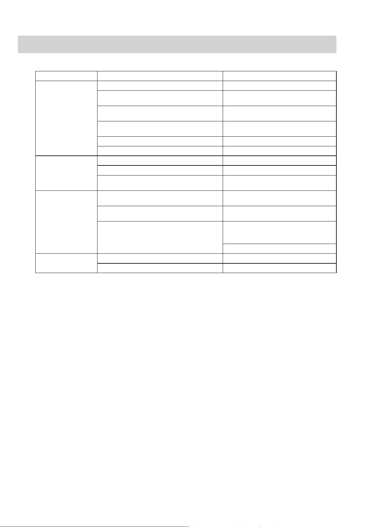
2. TROUBLESHOOTING
Power-Related Problems
Problem Possible Cause/Criteria Action
No beep sound and
AC power lamp does
not light in AC power
operation.
No beep sound and
the battery power
lamp does not light in
DC power operation.
DC power operation
time is shorter than
expected.
Power switch is not
operational.
No AC power input. Check the AC power input.
One or both AC inlet fuses is blown. Remove the cause of the blown fuse, then
Faulty connection between CN105 on the
MAIN board and power unit.
Faulty connection between CN103 on the
MAIN board and power SW board.
Faulty power supply unit. Replace the power supply unit.
Faulty power SW board. Replace the power SW board.
The battery is discharged. Charge the battery before use.
The battery is damaged. Replace the battery.
Faulty cable connection between CN021 on the
MAIN board and battery receptacle terminals.
The battery is near the end of its life (about 1
year).
Poor contact between the battery and its contact
points in the battery compartment.
The battery has had “memory effect” in which
its charge capacity is decreased by frequent
incomplete discharging and charging.
Faulty power SW board. Replace the power SW board.
Faulty MAIN board. Replace the MAIN board.
replace the fuse.
Check the connection of MAIN board and
power unit.
Check the connection.
Check the connection.
Replace the battery with a new one.
Clean the contact points between the
battery and its compartment terminals.
To clear this “memory effect”, fully
discharge the battery and then fully charge
it a few times.
Replace the battery with a new one.
2.2 Service Manual BSM-4100
Page 47

Display Problems
Problem Possible Cause/Criteria Action
No display and the backlight does not light.
No display, but the backlight lights.
Fine vertical or horizontal lines on the LCD.
Thick vertical or horizontal stripes on the
screen.
The characters or waveforms are distorted.
The display is dim and the brightness control
does not make it brighter.
The Diagnostic Check screen appears in the
monitor mode and “OK” is displayed at the
POWER ON CHECK RESULT.
The Diagnostic Check screen appears in the
monitor mode and an error message is
displayed at the POWER ON CHECK
RESULT. Refer to “Power On Self Check” in
Section 3.
The screen with a “Check Program Running”
message does not change to the next screen
after the power is turned on.
System error information appears at the upper
left corner on the screen in the monitor mode
and the instrument restarts.
More than 25 pixels on the screen do not light
or have abnormal color. Note that up to 25
pixels with such a problem is considered
normal.
No waveform is displayed but the connection
cord for each vital sign is recognized.
No waveform is displayed and the connection
cord for each vital sign is not recognized.
2. TROUBLESHOOTING
Faulty connection between CN108 on
the MAIN board and inverter.
Faulty connection between inverter
and LCD unit.
Faulty inverter board. Replace the inverter board.
Faulty backlight lamps. Replace the backlight lamps.
Faulty connection between CN102 on
the MAIN board and CN102 on the
connection board.
Faulty connection between CN103 on
the connection board and LCD unit.
Faulty LCD unit. Replace the LCD unit.
Faulty MAIN board. Replace the MAIN board.
Faulty LCD unit. Replace the LCD unit.
Faulty MAIN board. Replace the MAIN board.
Faulty MAIN board. Replace MAIN board.
Faulty MAIN board. Replace the MAIN board.
Faulty connection between CN102 on
the MAIN board, connection board
and LCD.
Battery operation. Set the POWER SAVE MODE to
Dirt on the touch screen (inside or
outside).
The backlight lamps are near the end
of its useful life (25,000 hours of
operation).
Faulty connection between CN108 on
the MAIN board and inverter board.
Faulty Operation board. Replace the Operation board.
Faulty MAIN board. Replace the MAIN board.
Faulty MAIN board. Replace the MAIN board.
Faulty DPU board. Replace the DPU board.
Software bug. Perform the system initialization.
Faulty MAIN board. Replace the MAIN board.
Faulty DPU board. Replace the DPU board.
Faulty MAIN board. Replace the MAIN board.
Faulty DPU board. Replace the DPU board.
Faulty LCD unit. Replace the LCD unit.
Faulty MAIN board. Replace the MAIN board.
Refer to each vital sign
troubleshooting section.
Check the connections.
Check the connections.
Check the connection.
Check the connection.
Check the connection.
OFF on the SYSTEM SETUP
screen.
Clean the surface of touch
screen.
Replace the backlight lamps.
Check the connection.
Refer to each vital sign
troubleshooting section.
Service Manual BSM-4100 2.3
Page 48

2. TROUBLESHOOTING
Sound Problems
Problem Possible Cause/Criteria Action
No sound.
No sound, except for a
hissing sound.
The sound is muffled or
distorted.
Faulty connection between CN006 on the
MAIN board and the speaker.
Faulty speaker. Replace the speaker.
Faulty MAIN board. Replace the MAIN board.
Faulty MAIN board. Replace the MAIN board.
Faulty speaker. Replace the speaker.
The speaker is blocked. Remove the object blocking the speaker.
Something foreign is touching the speaker. Remove the foreign matter.
The speaker is wrongly attached. Attach the speaker correctly.
Check the connection.
Key Operation Problems
Problem Possible Cause/Criteria Action
No key on the front panel
works.
A specified key on the
operation panel does not
work.
The workable key area
does not match the key
display on the screen.
Touch screen does not
work.
Function dials are not
operational.
Faulty connection between CN102 on the
Operation board and CN103 on the MAIN
board.
Faulty MAIN board. Replace the MAIN board.
Faulty Operation board. Replace the Operation board.
Faulty connection cable between CN102 on the
Operation board and CN103 on the MAIN
board.
Faulty Operation board.
Faulty MAIN board.
Incorrect calibration of the touch screen.
Faulty connection between the touch screen
and Connection board.
Faulty connection between connection board
and MAIN board.
The key function on
the entire screen does
not work.
The key function on a
partial screen such as
upper half screen does
not work
Faulty connection between the Operation board
and Function Dial board.
Faulty Function Dial board. Replace the Function Dial board.
Faulty MAIN board. Replace the MAIN board.
Check the connection.
Replace the connection cable.
Replace the Operation board.
Replace the MAIN board.
Calibrate the touch screen positioning.
Check the connection.
Check the connection.
Faulty connection
between the touch
screen and CN102 on
the Connection board.
Faulty MAIN board.
Faulty touch screen.
Faulty touch screen. Replace the touch screen.
Check the connection.
Replace the MAIN board.
Replace the touch screen.
Check the connection.
2.4 Service Manual BSM-4100
Page 49

Recording Problems
Problem Possible Cause/Criteria Action
Recording paper does not feed
properly.
For page-dependent recording
such as trendgraph and vital
sign list, the recording does
not start at the top of the page
Recording mark does
not appear on the
screen when the
record key is pressed.
Paper magazine open
mark appears on the
screen.
Out of paper mark
appears on the
screen.
Recording can be
performed when the
paper is manually
pulled out after the
record key is pressed.
Wrong position of the recording paper in the magazine. Load the paper into the magazine
Paper other than Nihon Kohden is used. Use the Nihon Kohden paper.
Photo sensor for detection of the black square on the paper is dirty. Clean the sensor.
Faulty connection between CN122 on the MAIN board and
recorder unit.
Faulty black square detection photo sensor or LED of the recorder
unit.
2. TROUBLESHOOTING
Faulty connection between CN103 on the
MAIN board and Power SW board.
Faulty Power SW board. Replace the Power SW board.
Faulty MAIN board. Replace the MAIN board.
Faulty connection between CN122 on the
MAIN board and recorder unit
Faulty magazine position sensing micro
switch of the recorder unit.
Faulty MAIN board. Replace the MAIN board.
Faulty connection between CN122 on the
MAIN board and recorder unit.
Faulty paper detection photo sensor or
LED of the reorder unit.
Faulty MAIN board. Replace the MAIN board.
Faulty connection between CN122 on the
MAIN board and recorder unit.
Faulty paper drive motor of the recorder
unit.
Faulty MAIN board. Replace the MAIN board.
Check the connection.
Check the connection.
Replace the micro switch. Refer to
Section 8 “Replaceable Parts List”.
Check the connection.
Replace the photo sensor and
LED. Refer to Section 8
“Replaceable Parts List”.
Check the connection.
Replace the motor. Refer to
Section 8 “Replaceable Parts List”.
correctly.
Check the connection.
Replace the photo sensor and
LED. Refer to Section 8
“Replaceable Parts List”.
The recorded data such as
waveform and grid has a faint
part on the paper.
There is missing dots on the
recorded data.
Straight line is recorded at the
same position on the paper.
There is different contrast
between the upper half and
lower half of the paper.
The paper speed is unstable
and waveform is compressed
or extended on time scale.
Abnormally loud rotating
sound of the paper drive motor
No recording on the paper
Faulty MAIN board. Replace the MAIN board.
Thermal array head is dirty
Paper other than Nihon Kohden is used.
Platen roller has a damage or is deformed. Replace the roller.
The supply voltage for thermal array head (+24 V DC) decreases.
Faulty thermal array head if the dots are missed at the same
position on the paper after the head is cleaned.
Faulty thermal array head or recorder unit after head is cleaned. Replace the head or recorder unit.
The thermal array head is incompletely attached to the recorder
unit.
Dirty gear or platen roller. Clean the gear and platen roller.
Faulty gear or platen roller Replace the faulty one.
Unstable turn of the paper
drive motor
Faulty gear or platen roller Replace the faulty one.
The heat-sensitive side of the paper is not faced to the thermal
array head.
Paper other than Nihon Kohden is used. Use the Nihon Kohden paper.
Faulty connection between CN121 on the MAIN board and
recorder unit.
The supply voltage for thermal array head (+24 V DC) decreases. Replace the MAIN board.
Faulty thermal array head. Replace the head.
Faulty MAIN board Replace the MAIN board.
Faulty motor Replace the motor.
Clean the head.
Use the Nihon Kohden paper.
Replace the MAIN board.
Replace the head.
Attach the head correctly.
Load the paper into the magazine
correctly.
Check the connection.
Service Manual BSM-4100 2.5
Page 50

2. TROUBLESHOOTING
ECG and Respiration by Impedance Method Problems
Problem Possible Cause/Criteria Action
ATTACH ELECTRODES
message is displayed even
after each electrode contact
part of the electrode lead is
short-circuited.
The time constant setting
cannot be changed.
Pacing spike is not
detected.
The setting, Number of electrodes, is set to a higher
number than the actual number of the electrodes.
The electrode lead, ECG connection cord or patient
cable is faulty.
ECG RESP1 board, ECG RESP2 board or ECG RESP3
board is faulty.
The ECG RESP3 board is faulty if the monitoring lead
setting can be changed.
Motherboard, DPU board or ECG RESP3 board is
faulty if the monitoring lead setting cannot be changed.
ECG RESP2 board, motherboard or DPU board is faulty
if the pacing spike detection setting, PACING REJECT,
is set to on.
ECG RESP3 board is faulty if the pacemaker rhythm is
not recognized in the 12 lead ECG interpretation.
Set the number of
electrodes correctly.
Replace the accessory with
a new one.
Replace the ECG input
block with a new one*.
Replace the ECG input
block with a new one*.
Replace the ECG input
block or DPU board with a
new one*.
Replace the ECG input
block or DPU board with a
new one*.
Replace the ECG input
block with a new one*.
The ECG waveform is
displayed with a different
ECG sensitivity from the
sensitivity setting.
Monitoring lead setting
cannot be changed but the
time constant setting can
be changed.
Display of 12 lead ECG
has something wrong.
Respiration waveform is
not displayed.
Respiration rate is wrong
and the respiration
sensitivity is out of control.
ECG waveform and
respiration waveform are
mixed.
Respiration waveform is
saturated and does not
return to the baseline
position but the sensitivity
is not too high.
ECG RESP1 board is faulty if the ECG waveform at a
specified lead is displayed with a different sensitivity
from the sensitivity setting.
ECG RESP2 board or ECG RESP3 board is faulty if the
ECG waveform at all the leads is displayed with a
different sensitivity from the sensitivity setting.
ECG RESP1 board, ECG RESP2 board or ECG RESP3
board is faulty.
ECG RESP3 board or motherboard is faulty if no 12
lead ECG waveforms are displayed in the 12 LEAD
window.
ECG RESP1 board, ECG RESP2 board or ECG RESP3
board is faulty if a specified lead of the 12 lead ECG
waveforms is not displayed in the 12 LEAD window
Electrode, electrode lead, ECG connection cord or
patient cable is faulty if the ECG waveform on the
screen has something wrong.
ECG RESP1 board, ECG RESP2 board, motherboard or
DPU board is faulty if the ECG waveform on the screen
has nothing wrong.
ECG RESP1 board or ECG RESP2 board is faulty. Replace the ECG input
Motherboard or DPU board is faulty. Replace the ECG input
ECG RESP2 board is faulty. Replace the ECG input
Replace the ECG input
block with a new one*.
Replace the ECG input
block with a new one*.
Replace the ECG input
block with a new one*.
Replace the accessory with
a new one.
Replace the ECG input
block or DPU board with a
new one*.
block with a new one*.
block or DPU board with a
new one*.
block with a new one*.
* ECG input block repair kit is required when one of the ECG RESP1 board, ECG RESP2 board, ECG RESP3 board
and motherboard has a failure. Refer to “Board Compatibility” in Section10 “Internal Switch Setting and Board
Compatibility”.
2.6 Service Manual BSM-4100
Page 51

SpO2 Problems
Problem Possible Cause/Criteria Action
The instrument does not
recognize the NK SpO
connection cord connected to
the SpO
instrument.
PULSE SEARCH message is
displayed even after the probe
is replaced and attachment site
is changed.
WEAK PULSE message is
displayed even after the probe
is replaced and attachment site
is changed.
SpO2 MODULE ERROR
message is displayed.
2 socket on the
2. TROUBLESHOOTING
NK SpO2 board or motherboard is faulty or
2
contact between them is poor if the ECG,
impedance method respiration and NIBP
measurements are enabled.
DPU board is faulty if the ECG, impedance
method respiration and NIBP measurements
Check the connection. Replace
the NK SpO
2 or ECG input block
with a new one* if the
connection has no problem.
Replace the faulty board with a
new one.
are disabled.
NK SpO
2 board is faulty. Replace the faulty board with a
new one.
NK SpO
board is faulty. Replace the faulty board with a
2
new one.
SpO2 module (Nellcor) is faulty or connection
between the motherboard and SpO
2 module is
poor if this error message is displayed, except
Check the connection. Replace
the faulty module with a new one
if the connection has no problem.
in the following case.
If the Nellcor SpO
connected to or disconnected from the SpO
2 connection cord is
2
socket just after the instrument is turned on, it
displays this error message at the power on
check.
Connect the SpO
cord and turn off the instrument.
Turn on the instrument 10
seconds or more after the power
is turned off.
2 connection
* ECG input block repair kit is required when one of the ECG RESP1 board, ECG RESP2 board, ECG RESP3 board
and motherboard has a failure. Refer to “Board Compatibility” in Section10 “Internal Switch Setting and Board
Compatibility”.
Service Manual BSM-4100 2.7
Page 52

2. TROUBLESHOOTING
Non-invasive Blood Pressure Problems
Problem Possible Cause/Criteria Action
NIBP MODULE
FAILURE message is
displayed.
NIBP SAFETY
CIRCUIT RUNNING
message is displayed.
AIR LEAK message is
displayed.
The instrument does not
recognize the air hose
connected to the NIBP
socket on the
instrument.
NIBP measurement data
on the screen is wrong.
The cuff does not inflate
when the NIBP
START/STOP key is
pressed.
DPU board or NIBP Safety board is faulty. Replace the faulty board with a new
Air hose is blocked. Check the air hose.
Air tube between the NIBP Safety board and
NIBP socket is blocked or NIBP Safety board or
DPU board is faulty if this message appears soon
after the NIBP START/STOP key is pressed and
NIBP pump sounds like it’s moving.
Air tube between the NIBP Measure board and
NIBP socket is blocked or NIBP Safety board or
DPU board is faulty if this message appears in a
minute after the NIBP START/STOP key is
pressed and NIBP pump sounds like it’s moving.
Cuff or air hose has an air leak. Replace the cuff or air hose with a
Air tube between the NIBP Safety board and
NIBP socket is loose or disconnected if the cuff
is not inflated when the NIBP pump sounds like
it’s moving.
Air tube between the NIBP Measure board and
NIBP socket is loose or disconnected or NIBP
Safety board is faulty if the cuff is inflated when
the NIBP pump sounds like it’s moving.
The air hose connector is faulty. Replace the air hose with a new one.
ECG RESP3 board or NIBP Safety board is
faulty or there is poor contact from the ECG
RESP3 board to NIBP Safety board if the ECG
and impedance method respiration can be
measured.
ECG RESP3 board, motherboard or DPU board
is faulty or there is a poor contact from the ECG
RESP3 board to DPU board if the ECG and
impedance method respiration cannot be
measured.
A wrong cuff size is used or the condition of the
cuff wrapped around the patient’s arm is not
correct.
DPU board is faulty if the ECG, impedance
method respiration and SpO
measured.
NIBP Measure board or DPU board is faulty or
there is a poor contact between the two boards if
the ECG, impedance method respiration and
2 can be measured.
SpO
If a message is displayed on the screen, follow
the message to solve the problem.
The Operation board, MAIN board or the cable
between the two boards is disconnected if there
is no message on the screen.
2 cannot be
one.
Check the air tube connection.
Replace the faulty board with a new
one if the air tube is not blocked.
new one.
Check the air tube connection.
Check the air tube connection.
Replace the faulty board with a new
one if the air tube connection has no
problem.
Check the connection from ECG
RESP3 board to NIBP Safety board
through the motherboard and DPU
board. Replace the faulty board with a
new one if the connection has no
problem.
Check the connection from the ECG
RESP3 board to DPU board through
the motherboard. Replace the faulty
board with a new one if the
connection has no problem.
Check the cuff size and the wrapping
condition.
Replace the faulty board with a new
one.
Check the connection between the two
boards. Replace the faulty board with
a new one if the connection has no
problem.
Refer to ERROR MESSAGES AND
TROUBLESHOOTING section in the
operator’s manual.
Check the cable connection. Replace
the faulty board with a new one if the
cable connection has no problem.
2.8 Service Manual BSM-4100
Page 53

Other Vital Sign Input Problems
Problem Possible Cause/Criteria Action
The instrument does
not recognize a
connection cord at a
multi-parameter
socket.
MPU MODULE
ERROR message is
displayed.
MPU FAILURE
message is displayed.
Any input parameters
for the multiparameter socket
cannot be measured at
any multi-parameter
sockets.
Invasive blood
pressure cannot be
measured.
CHECK SENSOR
message is displayed.
The connection cord is faulty. Replace the connection cord
The MP2 board is faulty if the connection cord is not
recognized at any multi-parameter sockets.
The MP3 board or MP2 board is faulty if the connection
cord is not recognized at the No. 3 multi-parameter
socket.
The MP1 board or MP2 board is faulty if the connection
cord is not recognized at the No. 1 or No. 2 multiparameter socket.
The connection cable between the motherboard and DPU
board is disconnected or the MP2 board, motherboard or
DPU board is faulty if this message always appears even
after the instrument is turned off and on again.
The MP2 board is faulty if this message sometimes
appears after the instrument is turned off and on again.
The EEPROM in the connector of the connection cord is
faulty if the cord connected to any multi-parameter
sockets displays this message.
The MP3 board or MP2 board is faulty if the cord
connection to No. 3 multi-parameter socket only displays
this message.
The MP1 board or MP2 board is faulty if the cord
connection to No. 1 or No. 2 multi-parameter socket only
displays this message.
The MP2 board is faulty if there is no error message on
the screen when the connection cord is connected to the
multi-parameter socket.
The blood pressure transducer or connection cord is
faulty.
The MP1 board or MP2 board is faulty if the blood
pressure cannot be measured at any multi-parameter
sockets or can be measured at one of them.
The MP3 board, MP2 board or motherboard is faulty if
the blood pressure cannot be measured at the No. 3 multiparameter socket only.
The MP1 board or MP2 board is faulty if the blood
pressure cannot be measured at the No. 1 and No. 2
multi-parameter sockets.
The blood pressure transducer is faulty. Replace the faulty blood
The MP1 board or MP2 board is faulty if the normal
transducer connected to each multi-parameter socket
through the connection cord displays this message or the
blood pressure can be measured at one of them.
The MP3 board, MP1 board or motherboard is faulty if
the normal transducer connected to the No. 3 multiparameter socket only displays this message.
The MP1 board or MP2 board is faulty if the normal
transducer connected to the No. 1 or No. 2 multiparameter socket displays this message.
2. TROUBLESHOOTING
with a new one.
Replace the faulty board with a
new one.
Check the cable connection.
Replace the MP2 board, ECG
input block or DPU board with
a new one* if the cable
connection has no problem.
Replace the board with a new
one.
Replace the connection cord
with a new one.
Replace the faulty board with a
new one.
Replace the faulty board with a
new one.
Replace the faulty blood
pressure transducer or
connection cord with a new
one.
Replace the faulty board with a
new one.
Replace the MP3 board, MP2
board or ECG input block with
a new one*.
Replace the faulty board with a
new one.
pressure transducer with a new
one.
Replace the faulty board with a
new one.
Replace the MP3 board, MP1
board or ECG input block with
a new one*.
Replace the faulty board with a
new one.
* ECG input block repair kit is required when one of the ECG RESP1 board, ECG RESP2 board, ECG RESP3 board
and motherboard has a failure. Refer to “Board Compatibility” in Section10 “Internal Switch Setting and Board
Compatibility”.
Service Manual BSM-4100 2.9
Page 54

2. TROUBLESHOOTING
Problem Possible Cause/Criteria Action
IBP measurement
data on the screen
is wrong.
Temperature cannot
be measured.
The blood pressure transducer is faulty. Replace the faulty blood pressure
transducer with a new one.
The MP2 board or MP1 board is faulty if the blood
pressure data is wrong at all the multi-parameter sockets
and temperature, FiO
2 and respiration rate (thermistor
Replace the faulty board with a
new one.
method) are not wrong at any multi-parameter sockets.
The MP2 board is faulty if not only the blood pressure
data but also temperature, FiO
2 and respiration rate are
wrong at all the multi-parameter sockets.
The MP1 board is faulty if the blood pressure data is
wrong at the No. 1 and No. 2 multi-parameter sockets.
The MP3 board is faulty if the blood pressure data is
wrong at the No. 3 multi-parameter socket only.
The thermistor probe is faulty. Replace the faulty probe with a
new one.
The MP2 board is faulty if the T1 and T2 temperatures
cannot be measured but thermistor method respiration
and FiO
2 can be measured at all the multi-parameter
Replace the faulty board with a
new one.
sockets or the temperatures can be measured at one of
the multi-parameter sockets.
The MP1 board is faulty if the T1 and T2 temperatures
and thermistor method respiration cannot be measured
at any multi-parameter sockets.
The MP3 board, MP2 board or motherboard is faulty if
the T1 and T2 temperatures cannot be measured at the
No. 3 multi-parameter socket only.
The MP1 board or MP2 board is faulty if the T1 and T2
temperatures cannot be measured at the No. 1 and No. 2
Replace the MP3 board, MP2
board or ECG input block with a
new one*.
Replace the faulty board with a
new one.
multi-parameter sockets.
Temperature
measurement data
on the screen is
wrong.
Respiration by
thermistor method
cannot be
measured.
Thermistor method
respiration
waveform has
something wrong
on the screen.
The thermistor probe is faulty. Replace the faulty probe with a
new one.
The MP2 board is faulty if the T1 and T2 temperatures
are wrong but thermistor method respiration and FiO2
Replace the faulty board with a
new one.
data are not wrong at any multi-parameter sockets.
The respiration pickup (thermistor probe) is faulty. Replace the faulty pickup with a
new one.
The MP1 board or MP2 board is faulty if the thermistor
method respiration cannot be measured but the T2
Replace the faulty board with a
new one.
temperature can be measured at all the multi-parameter
sockets or the respiration can be measured at one of the
multi-parameter sockets.
The MP1 board is faulty if the thermistor method
respiration and T1 and T2 temperatures cannot be
measured at any multi-parameter sockets.
The MP3 board, MP1 board or motherboard is faulty if
the thermistor method respiration cannot be measured at
the No. 3 multi-parameter socket only.
The MP1 board or MP2 board is faulty if the thermistor
method respiration cannot be measured at the No. 1 and
Replace the MP3 board, MP1
board or ECG input block with a
new one*.
Replace the faulty board with a
new one.
No. 2 multi-parameter sockets.
The respiration pickup (thermistor probe) is faulty. Replace the faulty pickup with a
new one.
The MP1 board or MP2 board is faulty if the respiration
rate is wrong but T2 temperature data is not wrong at
Replace the faulty board with a
new one.
any multi-parameter sockets.
* ECG input block repair kit is required when one of the ECG RESP1 board, ECG RESP2 board, ECG RESP3 board
and motherboard has a failure. Refer to “Board Compatibility” in Section10 “Internal Switch Setting and Board
Compatibility”.
2.10 Service Manual BSM-4100
Page 55

Problem Possible Cause/Criteria Action
FiO2 cannot be
measured.
The O2 sensor or connection cord is faulty. Replace the faulty O2 sensor or
connection cord with a new one.
The MP2 board is faulty if the FiO2 cannot be
measured but the T1 temperature can be measured at
all the multi-parameter sockets or the FiO
2 can be
Replace the faulty board with a new
one.
measured at one of the multi-parameter sockets.
2. TROUBLESHOOTING
FiO2 data on the
screen is wrong.
CO2 cannot be
measured.
CO2 data on the
screen is wrong.
CO cannot be
measured. (Injectate
temperature Ti or
blood temperature
Tb cannot be
measured or CO
curve does not
appear.)
CO data on the
screen is wrong. (Ti
or Tb temperature
data on the screen is
wrong.)
The MP3 board, MP2 board or motherboard is faulty
if the FiO
2 cannot be measured at the No. 3 multi-
parameter socket only.
The MP1 board or MP2 board is faulty if the FiO
2
cannot be measured at the No. 1 and No. 2 multi-
Replace the MP3 board, MP2 board
or ECG input block with a new
one*.
Replace the faulty board with a new
one.
parameter sockets.
The O2 sensor is faulty. Replace the faulty probe with a new
one.
The MP2 board is faulty if the FiO
2 is wrong but T2
temperature data is not wrong at any multi-parameter
Replace the faulty board with a new
one.
sockets.
The CO2 sensor or CO2 adapter is faulty. Replace the faulty CO2 sensor or
adapter with a new one.
The MP2 board is faulty if the CO2 cannot be
measured at any multi-parameter sockets or can be
Replace the faulty board with a new
one.
measured at one of them.
The MP3 board, MP2 board or motherboard is faulty
if the CO
2 cannot be measured at the No. 3 multi-
parameter socket only.
The MP1 board or MP2 board is faulty if the CO
2
cannot be measured at the No. 1 and No. 2 multi-
Replace the MP3 board, MP2 board
or ECG input block with a new
one*.
Replace the faulty board with a new
one.
parameter sockets.
The CO2 sensor is faulty. Replace the faulty sensor with a
new one.
The CO
2 adapter is faulty. Replace the faulty adapter with a
new one.
The catheter, bath probe, inline sensor or connection
cord is faulty.
Replace the faulty catheter, bath
probe, inline sensor or connection
cord with a new one.
The MP2 board is faulty if the Ti or Tb cannot be
measured at any multi-parameter sockets or the CO
Replace the faulty board with a new
one.
curve does not appear even when any multi-parameter
socket is used.
The MP3 board, MP2 board or motherboard is faulty
if the Ti or Tb cannot be measured at the No. 3 multiparameter socket only or the CO curve does not
Replace the MP3 board, MP2 board
or ECG input block with a new
one*.
appear with the No. 3 socket.
The MP1 board or MP2 board is faulty if the Ti or Tb
cannot be measured at the No. 1 and No. 2 multi-
Replace the faulty board with a new
one.
parameter sockets or the CO curve does not appear
with the No. 1 and No. 2 sockets.
The catheter, bath probe or inline sensor is faulty. Replace the faulty catheter, bath
probe or inline sensor with a new
one.
The MP2 board is faulty if the Ti data is wrong but
FiO
2 data can be measured at all the multi-parameter
Replace the faulty board with a new
one.
sockets or Tb data is wrong but thermistor method
respiration can be measured at all the multi-parameter
sockets.
* ECG input block repair kit is required when one of the ECG RESP1 board, ECG RESP2 board, ECG RESP3 board
and motherboard has a failure. Refer to “Board Compatibility” in Section10 “Internal Switch Setting and Board
Compatibility”.
Service Manual BSM-4100 2.11
Page 56

2. TROUBLESHOOTING
ECG/BP Output Problems
Problem Possible Cause/Criteria Action
The instrument does not
output the ECG, HT
(heart rate) or BP signal
from the ECG/BP OUT
socket.
The ECG or BP
waveform from the
ECG/BP OUT socket is
wrong.
The ECG/BP output cable is faulty. Replace the ECG/BP output cable
The ECG and HT signals do not output without
ECG measurement.
The BP signal is not output if the blood
pressure is measured at the No. 2 or No. 3
multi-parameter sockets.
The connection cable between the DPU board
and ECG RESP1 board is disconnected if the
ECG, HT and BP are not output.
The DPU board or ECG RESP1 board is faulty
if one of the three signals (ECG, HT and BP) is
not output.
The DPU board is faulty if the ECG or BP
waveform amplitude is wrong at the ECG/BP
OUT socket but the ECG and invasive blood
pressure waveforms are correctly displayed on
the screen.
with a new one.
Measure the ECG.
Measure the invasive blood pressure
at the No. 1 multi-parameter socket.
Check the connection.
Replace the DPU board or ECG input
block with a new one*.
Replace the faulty board with a new
one.
* ECG input block repair kit is required when one of the ECG RESP1 board, ECG RESP2 board, ECG RESP3 board
and motherboard has a failure. Refer to “Board Compatibility” in Section10 “Internal Switch Setting and Board
Compatibility”.
2.12 Service Manual BSM-4100
Page 57

Option Problems
Problem Possible Cause/Criteria Action
The instrument does
not display the full
disclosure window.
The instrument does
not transmit the
patient’s data at all.
The instrument has
no communication
with the other bedside
monitors and central
monitors.
2. TROUBLESHOOTING
The optional QM-421P flash disk card is not
installed.
The QM-421P installation, QM-421P card or
MAIN board is faulty if “QM-421P” is not
displayed at the “OPTION” on the
DIAGNOSTIC CHECK screen.
“SYSTEM INITIALIZE” is not done or the
QM-421P card or MAIN board is faulty if
“QM-421P” is displayed at the “OPTION”
on the DIAGNOSTIC CHECK screen.
The optional ZB-800P transmitter is not
connected to the instrument.
The channel for the ZB-800P is not set at the
central monitor or telemetry system.
The ZB-800P or DPU board is faulty. Replace the faulty transmitter or DPU board
The optional QI-101P network card is not
installed into the instrument.
The network
communicating
symbol does not
appear on the
screen.
The network card is
poorly inserted into the
slot of the instrument.
The network cable such
as 10Base-T cable is
poorly connected
between the network
card and hub.
The hub connected to
the instrument is not
turned on or is faulty.
The instrument is
connected to the hub
with 10Base-T cross
wiring cable.
The instrument is
directly connected to the
central monitor with
10Base-T straight
wiring cable.
The network cable is
faulty.
The network card or
MAIN board is faulty.
Install the card into the slot on the MAIN
board completely.
Install the card into the slot on the MAIN
board completely. Replace the faulty card or
board with a new one if the problem still
exists after the card installation.
Touch the “SYSTEM INITIALIZE” key on
the DIAGNOSTIC CHECK screen to
perform the system initialization. Replace
the faulty card or board with a new one if
the problem still exists after the system
initialization.
Connect the ZB-800P to the instrument
completely.
Set the channel correctly at the central
monitor or telemetry system.
with a new one.
Install the network card into the instrument
completely.
Firmly insert the network card into the slot.
Firmly connect the network cable between
the network card and hub.
Turn on the hub. Replace the hub with a new
one if the problem still exists after the power
is turned on.
Use the correct internal wiring 10Base-T
cable.
Replace the network cable with a new one.
Replace the faulty network card or MAIN
board with a new one.
Service Manual BSM-4100 2.13
Page 58

Section 3 Diagnostic Check
Introduction ......................................................................................................................... 3.1
Power On Self Check .......................................................................................................... 3.2
Calling Up the DIAGNOSTIC CHECK Screen ......................................................................3.4
Calling Up the Error History .................................................................................................3.5
Error Codes ...............................................................................................................3.5
System Errors ........................................................................................................... 3.6
Initializing the System .........................................................................................................3.7
Performing Manual Check and Other Checks ......................................................................3.8
Calling Up the MANUAL CHECK MENU Screen........................................................3.9
CPU Check Menu Items.......................................................................................... 3.10
ROM Check .................................................................................................. 3.10
RAM Check ..................................................................................................3.11
Hard Key Check ............................................................................................ 3.12
Touch Key Check .......................................................................................... 3.13
Sound Check ................................................................................................ 3.14
COM RAM Check ......................................................................................... 3.15
ALARM INDICATOR Check ........................................................................... 3.16
OTHER Check .............................................................................................. 3.17
MEMORY CARD Check ................................................................................ 3.18
ATA CARD Check..........................................................................................3.19
Backlight Check ............................................................................................ 3.20
CRTC Check Menu Items .......................................................................................3.21
GRAPHIC MEMORY Check and CHARACTER MEMORY Check ................ 3.21
GRAPHIC DRAW Check ............................................................................... 3.22
CHARACTER DRAW Check .......................................................................... 3.24
IMAGE DRAW Check ...................................................................................3.26
DPU Check Menu Items.......................................................................................... 3.27
D/A ADJUST................................................................................................. 3.27
AD TEST ....................................................................................................... 3.28
AUX I/F Check ..............................................................................................3.29
NIBP Check ..................................................................................................3.30
DPU ROM Check ..........................................................................................3.40
DPU RAM Check .......................................................................................... 3.41
DPU COM RAM Check ................................................................................. 3.42
Service Manual BSM-4100 3C.1
Page 59

COM Check Menu Items ......................................................................................... 3.43
WS RECORDER Check ................................................................................ 3.43
SERIAL I/F Check ........................................................................................ 3.44
NETWORK CARD Check .............................................................................. 3.45
MULTI PARAMETER UNIT Check ................................................................ 3.48
ECG Check ................................................................................................... 3.49
Recorder and Control Block Checks........................................................................ 3.50
SELF-TEST-PRO No.1 .................................................................................. 3.50
SELF-TEST-PRO No.2 .................................................................................. 3.51
SELF-TEST-PRO No.3 .................................................................................. 3.52
Calibration of Touch Screen ..................................................................................... 3.53
3C.2 Service Manual BSM-4100
Page 60

Introduction
3. DIAGNOSTIC CHECK
The instrument has two check programs which automatically or manually diagnose
the instrument. The automatic check program (power on self check) is executed
whenever the instrument is turned on. The manual check program can be executed
at any time.
All errors detected during the power on self check, manual check, and any time in
monitor mode are stored in an error history table that you can view.
The manual check, error history, and system setup and initialization are accessed
from the DIAGNOSTIC CHECK screen.
Service Manual BSM-4100 3.1
Page 61

3. DIAGNOSTIC CHECK
Power On Self Check
The following icon appears during the power on self check.
If no error is detected, the monitor mode begins and the patient monitoring display
appears. If a serious error which does not allow the host CPU to execute the system
program any more is detected, the screen changes to the following DIAGNOSTIC
CHECK screen and the error mesage is displayed.
If a minor error such as “Backup data is damaged” or “Super capacitor is
discharged” is detected, the monitor mode begins and the patient monitoring
display appears after the power on self check. The detected error is stored in the
error history table. Refer to “Calling Up the Error History” section.
3.2 Service Manual BSM-4100
Page 62

3. DIAGNOSTIC CHECK
The MAIN board and DPU board are checked as follows:
• CPU ROM CHECK: Checks the system ROM for the host CPU on the MAIN
board. The MAIN board will be faulty if an error which causes a partial screen
problem is found.
• CPU RAM CHECK: Checks the system RAM for the host CPU and patient data
storage. The MAIN board will be faulty if an error which causes a screen
problem is found.
• DPU ROM CHECK: Checks the system ROM for the CPU on the DPU board.
The DPU board will be faulty if an error which causes a screen problem or data/
waveform display problem is found.
• DPU RAM CHECK: Checks the system RAM for the CPU on the DPU board.
The DPU board will be faulty if an error which causes a screen problem or data/
waveform display problem is found.
• 2PORT RAM CHECK: Checks the common memory (Dual port RAM on the
DPU board) for the communication between the MAIN and DPU boards. The
DPU board will be faulty if an error which causes a screen problem or data/
waveform display problem is found.
• CLOCK IC CHECK: Checks the real-time clock IC on the MAIN board. If the
date or time is wrong, the clock IC is initialized. The MAIN board will be faulty
if an error is found.
• A/D CHECK: Checks the system counter. The MAIN board will be faulty if an
error which disables the data processing function is found.
• E2PROM CHECK: Checks the backup memory for the system setup data storage.
If the data is wrong, the memory is initialized. The MAIN board will be faulty if
an error is found.
If a serious error is found in the abovementioned checks, the instrument displays
the DIAGNOSTIC CHECK screen without displaying the patient monitoring
screen.
The following data checks are also done. The data is corrected if necessary.
• BACK UP CHECK: Checks the backed up data. If the backed up data has
something wrong, the data is initialized.
• TIME CHECK: Checks correctness of the time.
• GET TIME CHECK: Checks the period during the AC power off in the battery
operation and adjusts the time data if it is wrong.
Service Manual BSM-4100 3.3
Page 63

3. DIAGNOSTIC CHECK
Calling Up the DIAGNOSTIC CHECK Screen
Use this screen to view the error history or perform manual check or system setup
and initialization.
1. With the power off, press the Power switch while pressing the SILENCE
ALARMS key. Continue pressing the SILENCE ALARMS key until the
DIAGNOSTIC CHECK screen appears.
2. To exit the DIAGNOSTIC CHECK screen and return to the patient monitoring
mode, touch the “MONITOR MODE” key.
3.4 Service Manual BSM-4100
Page 64

Calling Up the Error History
The ERROR HISTORY screen shows the error history of the instrument. The error
code, board name, time, and date the error occurred are listed on this screen. For an
explanation of error codes, see the “Error Codes” section. The error history data is
deleted whenever system initialization is performed.
1. From the DIAGNOSTIC CHECK screen, touch the “HISTORY” key. The
HISTORY screen appears. Then, touch the “ERROR HISTORY” key to display
the error history.
3. DIAGNOSTIC CHECK
Error Codes
2. Touch the “PRINT” key to print the screen with the recorder.
3. To return to the MANUAL CHECK MENU screen, touch the “RETURN” key.
When a fault is detected during operation or during the power on self check, the
error is stored in the error history table. The error codes stored in the error history
are only deleted when system initialization is performed. If the memory space for
the error history is filled up, however, the oldest error code is deleted when a new
error code is added.
The message and description of each error code are described in the following
table:
Error Code Message Description
0110 WATCH DOG Interrupt from the watch dog timer
0210 BUS Bus error occurred when an empty address was
selected
0220 ADDRESS Address error when a word accessed the odd
address
0230 ILLEGAL Illegal command is executed
Service Manual BSM-4100 3.5
Page 65

3. DIAGNOSTIC CHECK
0240 ZERO Zero division error
0250 CHK Check command error occurred during check
0260 TRAP Trap command error
0270 PRIVILEGE Privilege error
0280 SPURIOUS Undefined interrupt error
0290 UNDEFINED Not used
02A0 UNDEFINED Not used
02B0 UNDEFINED Not used
02C0 OTHER Error from faults other than ones described
above
0310 OS Error detected by the OS
0410 CPU (ROM) Error detected by CPU ROM check
0411 WS (ROM) Error detected by WS ROM check
0420 CPU (RAM) Error detected by CPU RAM check
0430 CPU (CMRAM) Error detected by CPU communication RAM
check
0440 A/D, D/A Error detected by A/D and D/A check
0470 CLOCK Error detected by the real time clock
0472 CLK DATA Error detected by CLOCK DATA check
0480 E2PROM Error detected by EEPROM check
0510 ATA CARD
ACCESS ERROR Error detected by ATA card (QM-421P) check
0400 OTHER Error from faults other than those described
above
A410 DPU (ROM) Error detected by DPU ROM check
A420 DPU (RAM) Error detected by DPU RAM check
A430 DPU (CMRAM) Error detected by DPU communication RAM
check
System Errors
3.6 Service Manual BSM-4100
A system error occurs when a fatal fault is detected during operation. All operation
of the instrument is halted and the CPU operation status data at the system error
appear on the left top of the screen. The system error is mostly stored in the error
history table. In a few seconds after the status data is displayed, the instrument
restarts. If the instrument repeats the restart, the MAIN board will be faulty.
Page 66

Initializing the System
You can delete all stored waveforms and data and the error history and return all
settings to the factory defaults.
Initializing the system deletes all the patient data and error history, and
returns the setting conditions to their default settings.
3. DIAGNOSTIC CHECK
CAUTION
1. From the DIAGNOSTIC CHECK screen, touch the “SYSTEM INITIALIZE” key
until a SYSTEM INITIALIZE confirmation message appears. (Approximately 3
seconds)
All data and user settings are deleted.
2. To exit the DIAGNOSTIC CHECK screen and return to the patient monitoring
mode, touch the “MONITOR MODE” key.
Service Manual BSM-4100 3.7
Page 67

3. DIAGNOSTIC CHECK
Performing Manual Check and Other Checks
The following checks are available.
With the SILENCE ALARMS key pressed
DIAGNOSTIC CHECK
MANUAL CHECK
CPU CHECK CRTC CHECK
ROM Check
RAM Check
Hard Key Check
Touch Key Check
SYSTEM SETUP SYSTEM INITIALIZE ERROR HISTORY
Character Memory
Check
Graphic Memory
Check
Graphic Draw Check
Power ON
DPU CHECK
D/A adjust
AD test
AUX I/F Check
NIBP Check
With the record key and NIBP
INTERVAL key pressed until the
patient monitoring screen appears
Press the MENU key
TOUCH PANEL CALIBRATION
COM CHECK
WS Recorder
Check
Serial I/F Check
Network Card
Check
Recorder and
Control Block
Checks
SELF-TEST-PRO
No. 1
SELF-TEST PRO
No. 2
Sound Check
COM RAM Check
Alarm Indicator
Check
Other Check
Memory Card Check
ATA Card Check
Back Light Check
In most of these checks, if a fatal error is detected during the check, the operating system hangs. When the system hangs, turn
off the instrument and remove the cause.
ASCII Draw Check
Image Draw Check
Report Draw Check
ROM Check
RAM Check
COM RAM Check
Multi Parameter
Unit Check
ECG Check
EXT I/F Check
SELF-TEST PRO
No.3
3.8 Service Manual BSM-4100
Page 68

3. DIAGNOSTIC CHECK
Calling Up the MANUAL
CHECK MENU Screen
1. From the DIAGNOSTIC CHECK screen, touch the “MANUAL CHECK” key.
The MANUAL CHECK MENU screen appears.
2. To test each item from the MANUAL CHECK MENU screen, touch a menu
item key.
3. To return to the DIAGNOSTIC CHECK screen, touch the “RETURN” key.
4. To exit the DIAGNOSTIC CHECK screen and return to the patient monitoring
mode, touch the “MONITOR MODE” key.
Service Manual BSM-4100 3.9
Page 69

3. DIAGNOSTIC CHECK
CPU Check Menu Items
The CPU check menu items check the function of the CPU peripherals such as
ROMs, RAMs, Switches, Touch Key, Sound generators, Alarm indicators and
external memory modules.
ROM Check
This item checks the ROMs on the MAIN board by the CRC (cyclic redundancy
check) technique. This check assigns a count number when one set of checks is
successfully completed. A set of checks takes about 1 minute and 30 seconds.
If an error message appears, the MAIN board will be faulty.
Procedure to Start and Exit the ROM Check Program
1. To select the ROM Check, touch the “ROM CHECK” key. The instrument
automatically starts the ROM check.
2. The instrument repeats the check and increments the pass count until you
touch the “RETURN” key.
3. If the check program finds an error, it displays the type of ROM (PROGRAM or
IMAGE) in the above area.
4. To return to the MANUAL CHECK MENU screen at any time, touch the
“RETURN” key.
3.10 Service Manual BSM-4100
Page 70
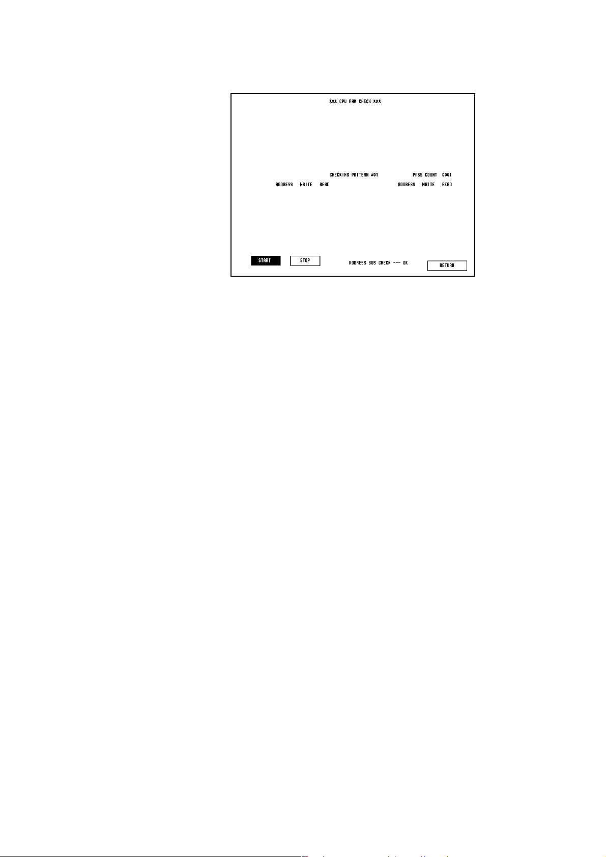
3. DIAGNOSTIC CHECK
RAM Check
This item checks the RAM on the MAIN board by comparing the test patterns it
first wrote to the RAM with the test patterns it later read from the RAM. This test
uses 15 test patterns and assigns a count number when a comparison of the 15 test
patterns is successfully completed. The comparison of all the test patterns in this
check takes about 4 minutes.
This check deletes the patient data. If an error message appears, the MAIN board
will be faulty.
Procedure to Start, Stop, and Exit the RAM Check Program
1. To select the RAM Check, touch the “RAM CHECK” key. The instrument
automatically starts the RAM check.
2. The instrument repeats the check and increments the pass count until the
operator touches the “RETURN” key.
3. If the check program finds an error, it displays the address, write data and read
data as shown in the above table.
4. To stop the check temporarily, touch the “STOP” key. The “START” key name
changes to normal and the “STOP” key is highlighted.
To continue the check, touch the “START” key again.
5. To return to the MANUAL CHECK MENU screen at any time, touch the
“RETURN” key.
Service Manual BSM-4100 3.11
Page 71

3. DIAGNOSTIC CHECK
Hard Key Check
This item checks the operation of the hard keys on the front panel and the function
dials. The hard key and dial layout appear. Pressing the hard key or rotating the
function dial usually highlights the corresponding hard key or dial on the screen.
If the pressed hard key is not highlighted, the hard key may be faulty. If more than
one hard key has this symptom, the operation board, function dial board or MAIN
board will be faulty.
NOTE
The key does not give a key click sound when it is pressed in this
check.
Procedure to Start the Check Keys or to Exit the Key Check Program
1. To check the hard keys, touch the “HARD KEY CHECK” key.
2. In the above screen, confirm that the corresponding pressed key is highlighted
on the screen.
3. To return to the MANUAL CHECK MENU screen, touch the “RETURN” key.
3.12 Service Manual BSM-4100
Page 72

3. DIAGNOSTIC CHECK
Touch Key Check
This item checks the touch key operation and positioning. When you start the
check, the screen changes to the touch key check screen, and indicates the position
where you touched. When you touch the screen and move your finger or touch
pen, the target mark traces your position.
If the position of the target mark and the touched position do not match, calibrate
the touch screen.
If you execute the touch key calibration and the position is still incorrect, the
connection board, touch screen, or MAIN board will be faulty.
Procedure to Start the Touch Key Check or to Exit the Touch Key Check Program
1. To check the touch key, touch the “TOUCH KEY CHECK” key.
2. On the above screen, confirm that the touched position matches the target
mark on the screen.
3. To return to the DIAGNOSTIC CHECK screen, press the HOME key.
Service Manual BSM-4100 3.13
Page 73

3. DIAGNOSTIC CHECK
Sound Check
This item checks the 7 types of sounds generated by the instrument. This check
can also be used to check the alarm circuit and the QRS beep circuit. Check the
quality of sound, loudness, noise, incorrect sound, etc.
If there is no sound or distorted sound, the speaker or MAIN board will be faulty.
Procedure to Check the Sound
1. To check the sound, touch the “SOUND CHECK” key.
2. Touch a sound key, such as “ALARM SOUND1”, “ALARM SOUND2”,
“ALARM SOUND3”, “QRS BEEP (HIGH TONE)”, “QRS BEEP (LOW TONE)”,
“QRS BEEP (VARIABLE)”, “KEY CLICK” to start the check for that sound.
3. To stop the check, touch the “SOUND STOP” key.
4. To change the sound volume, touch the “↑” or “↓” key.
5. To return to the MANUAL CHECK MENU screen, touch the “RETURN” key.
3.14 Service Manual BSM-4100
Page 74

3. DIAGNOSTIC CHECK
COM RAM Check
This item checks the dual port RAM for communication between the host CPU on
the MAIN board and CPU on the DPU board. The check method is the same as the
system RAM check. The check program indicates the address, write data and read
data if an error is detected.
This RAM is located on the DPU board. Therefore if an error is detected, the DPU
board or connector which connects the MAIN and DPU boards will be faulty.
Procedure to Start, Stop, and Exit the COM RAM Check Program
1. To select the COM RAM Check, touch the “COM RAM CHECK” key. The
instrument automatically starts the RAM check.
2. If the check program finds an error, it displays the address, write data and read
data as shown in the above table.
3. To stop the check temporarily, touch the “STOP” key. The “START” key name
changes to normal and the “STOP” key is highlighted.
To continue the check, touch the “START” key again.
4. To return to the MANUAL CHECK MENU screen, touch the “RETURN” key.
Service Manual BSM-4100 3.15
Page 75

3. DIAGNOSTIC CHECK
ALARM INDICATOR Check
This item checks the function of the alarm indicator located on the top of the
instrument. Check the light of indicator lamp according to the screen indication.
If the color does not light, the connection cable is loose or disconnected or the
MAIN board or indicator board will be faulty. If the indicator lights partially, the
indicator board is faulty.
Procedure to Start the ALARM INDICATOR Check Program
1. To select the Alarm Indicator Check, touch the “ALARM INDICATOR
CHECK” key. The lighting color is highlighted on the screen sequentially.
2. To return to the MANUAL CHECK MENU screen, touch the “RETURN” key.
3.16 Service Manual BSM-4100
Page 76

3. DIAGNOSTIC CHECK
OTHER Check
This item checks the clock IC and backup NVRAM (EEPROM). The NVRAM
contains the system setup data. The check program checks correspondence
between write and read data with the stored data retention. Therefore, this check
does not damage the system setup data. If the clock IC and NVRAM have no error,
the “OK” message appears on the screen and current date and time appear at the
top of the screen. If an error message appears, the MAIN board will be faulty.
Procedure to Execute the OTHER Check Program
1. To select the OTHER Check, touch the “OTHER CHECK” key.
The program starts the checking automatically and several minutes later, the
program displays the result of checking.
2. To return to the MANUAL CHECK MENU screen, touch the “RETURN” key.
Service Manual BSM-4100 3.17
Page 77

3. DIAGNOSTIC CHECK
MEMORY CARD Check
This item checks the inserted PCMCIA card and its interface. There are two
checks. The ATTRIBUTE CHECK displays the dump list of attribute area which is
in the PCMCIA card. The COMMON CHECK is the write/read check for common
area. This check continues until you touch the “STOP” key or “RETURN” key.
The check method is the same as the system RAM check.
If the PCMCIA card is not inserted, the program displays the CARD NOT
INSERTED message on the screen.
If an error is detected, the PCMCIA card or MAIN board will be faulty.
Procedure to Start MEMORY CARD Check Program
1. To select the MEMORY CARD Check, touch the “MEMORY CARD CHECK”
key.
2. To display the dump list of attribute area which is in the memory card, touch
the “ATTRIBUTE CHECK” key.
3. To start the common check, touch the “COMMON CHECK” key.
If the check program finds an error, it displays the address, write data and read
data as shown in the above table.
4. To stop the check temporarily, touch the “STOP” key. The “START” key name
changes to normal and the “STOP” key is highlighted.
To continue the check, touch the “START” key again.
5. To return to the MANAUL CHECK MENU screen, touch the “RETURN” key.
3.18 Service Manual BSM-4100
Page 78
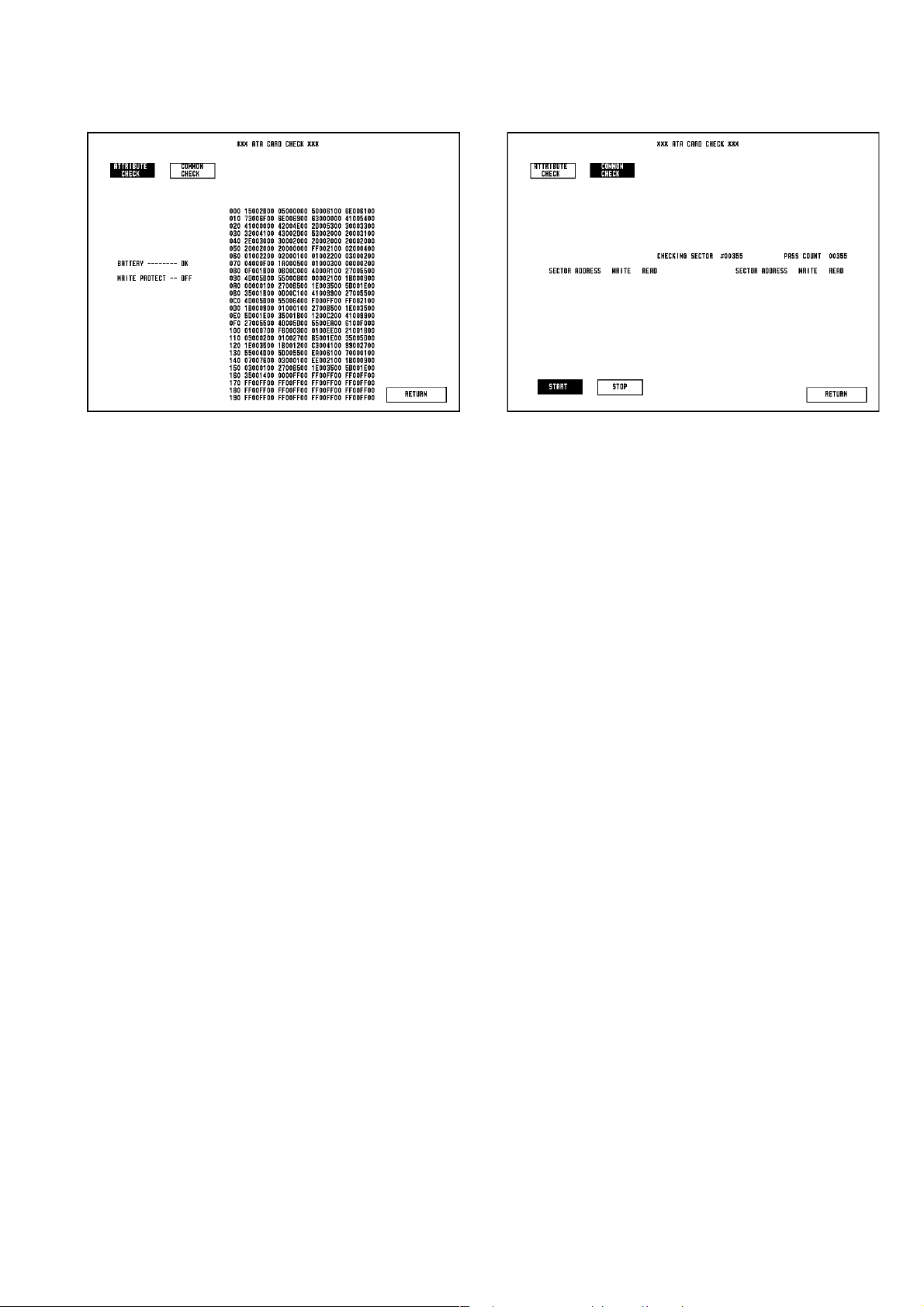
3. DIAGNOSTIC CHECK
ATA CARD Check
This item checks the ATA card (QM-421P) and its interface. This check is almost
the same as the MEMORY CARD check, except for the COMMON CHECK.
The COMMON CHECK is the write/read check for common area by each sector.
This check continues until you touch the “STOP” key or “RETURN” key.
The check method is the same as the system RAM check.
If an error is detected, the QM-421P or MAIN board will be faulty.
Procedure to Start and Exit the ATA CARD Check Program
1. To select the ATA CARD Check, touch the “ATA CARD CHECK” key.
2. To display the dump list of attribute area which is in the ATA CARD, touch the
“ATTRIBUTE CHECK” key and touch the “NEXT PAGE” or “PREVIOUS
PAGE” keys, if necessary.
3. To start the common check, touch the “COMMON CHECK” key.
If the check program finds an error, it displays the address, write data and read
data as shown in the above table.
4. To stop the check temporarily, touch the “STOP” key. The “START” key name
changes to normal and the “STOP” key is highlighted.
To continue the check, touch the “START” key again.
5. To return to the MANUAL CHECK MENU screen, touch the “RETURN” key.
Service Manual BSM-4100 3.19
Page 79
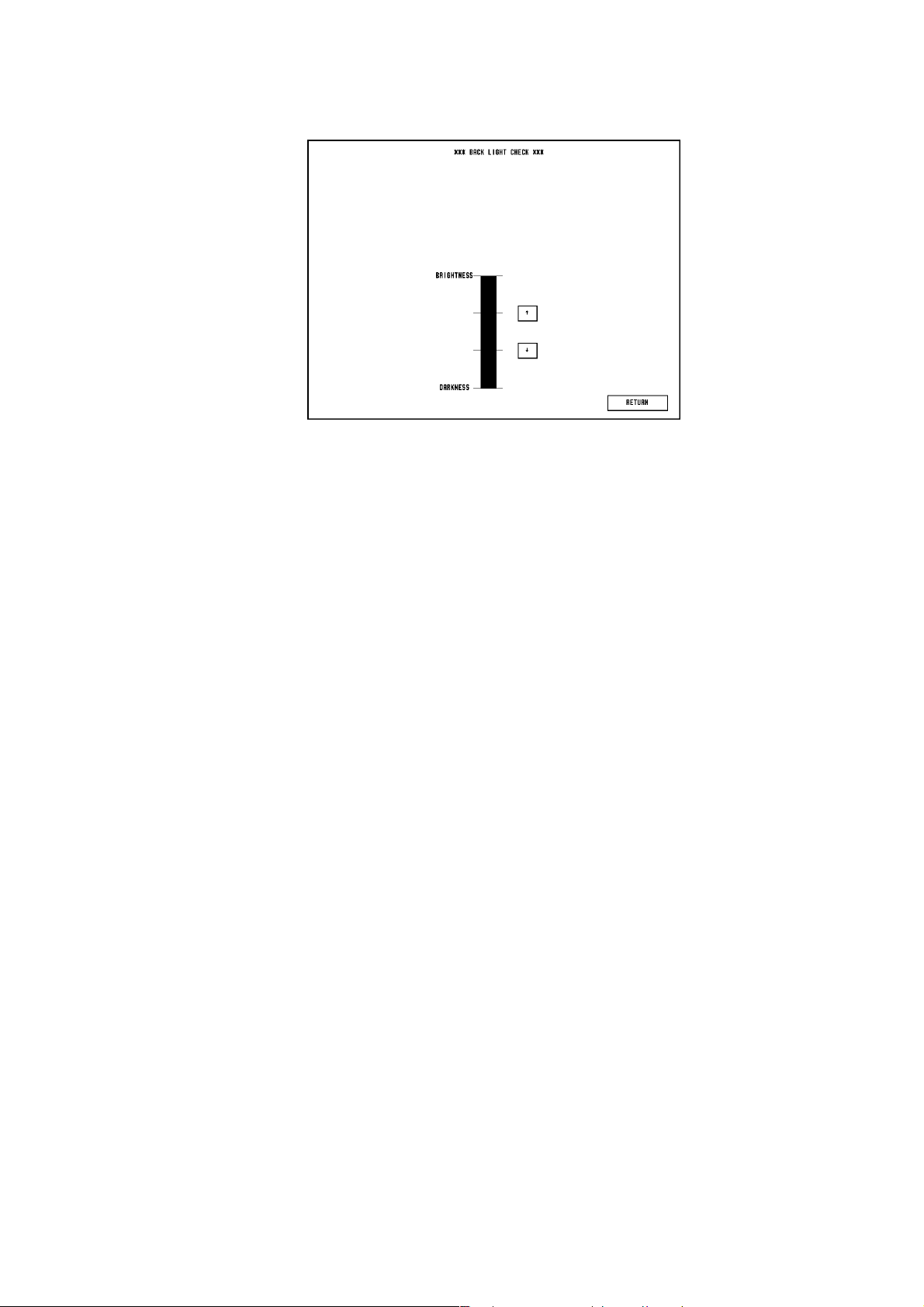
3. DIAGNOSTIC CHECK
Backlight Check
This item checks the brightness control of the LCD backlight. While the
brightness is manually changed, check that it changes smoothly with no twinkling.
Check that the backlight goes off and has no twinkling when the brightness is set
to minimum.
If the brightness does not change smoothly or the light goes off in the middle of
the brightness bar on the screen, it indicates the end of life of the backlight or
faulty inverter board.
In that case, replace the inverter board, or fluorescent tube which is located on the
top of the backlight unit.
Procedure to Check the Brightness of the LCD Backlight
1. To select the Backlight Check, touch the “BACK LIGHT CHECK” key.
To control the brightness, touch the bargraph or the “↑” or “↓” key to increase
or decrease the brightness.
2. To return to the MANUAL CHECK MENU screen at any time, touch the
“RETURN” key.
3.20 Service Manual BSM-4100
Page 80

3. DIAGNOSTIC CHECK
CRTC Check Menu Items The CRTC check menu items check the function of the display control block,
including the LCD unit. These check results cannot be recognized by the host
CPU, so you must judge the result.
If an error is found, the MAIN board will be faulty.
GRAPHIC MEMORY Check and CHARACTER MEMORY Check
These items check the Graphic RAM and Character RAM on the MAIN board for
the waveform display or character display by the write/read check technique. If an
error is detected, the error bank, address and data are displayed as a table.
Procedure to Start the GRAPHIC MEMORY Check and CHARACTER
MEMORY Check Program
1. To select the GRAPHIC MEMORY Check or CHARACTER MEMORY
Check, touch the “GRAPHIC MEMORY CHECK” or “CHARACTER
MEMORY CHECK” key.
The “START” key is highlighted to indicate the process of checking.
2. If the check program finds an error, it displays the address (and block bank),
write data and read data as shown in the above table.
3. To stop the check temporarily, touch the “STOP” key. The “START” key name
changes to normal and the “STOP” key is highlighted.
To continue the check, touch the “START” key again.
4. To return to the MANUAL CHECK MENU screen, touch the “RETURN” key.
Service Manual BSM-4100 3.21
Page 81
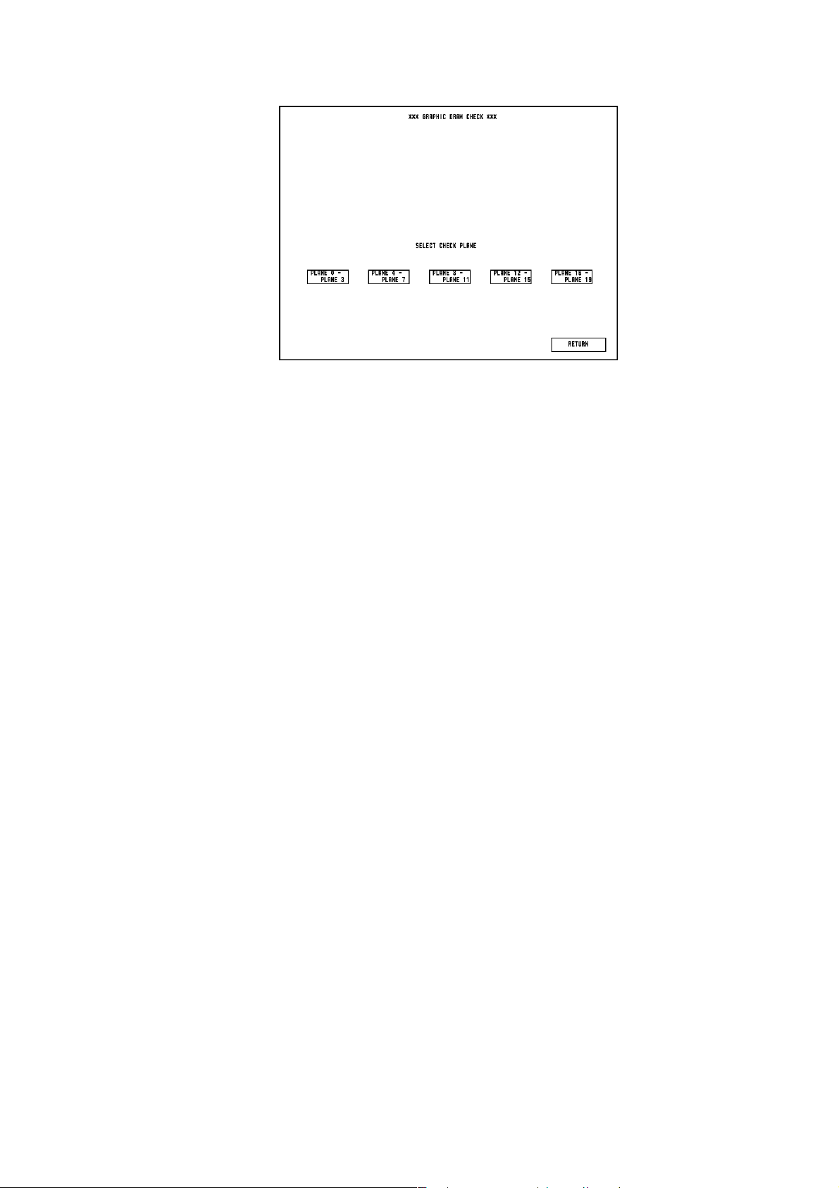
3. DIAGNOSTIC CHECK
GRAPHIC DRAW Check
This item checks the function of the graphic draw plane. Check the figure of
display and colors. At the same time, it checks for defects of LCD pixels all over
the screen.
The plane for wave/graphic screen is in 20 screens and the check program displays
4 planes at a time.
If the screen has a wrong display, the MAIN board or LCD unit will be faulty.
Procedure to Execute the GRAPHIC DRAW Check Program
1. To select the Check, touch the “GRAPHIC DRAW CHECK” key.
Touch the “PLANE 0 - PLANE 3” to “PLANE 16 - PLANE 19” key to display
the plane combination.
2. When the program starts, it draws the grid line first. If you touch the screen,
the pattern changes to the triangular waveform.
After touching the screen again, the pattern on the screen is displayed all over
the screen. The patterns are changed every time the screen is touched.
3. By rotating the upper function dial, the displaying plane(s) change, such as 0,
1, 2, 3 or ALL (the number depends on the plane combination).
To select the waveform to be modified, rotate the lower function dial.
The displayed color can be changed by pressing the SILENCE ALARMS key.
4. At the triangular waveform display mode, you can scroll the waveform by
pressing the MENU key.
Press the RECORD key to change the amplitude of each waveform.
5. To return to the GRAPHIC DRAW CHECK screen, press the HOME key.
6. To return to the MANUAL CHECK MENU screen, touch the “RETURN” key.
3.22 Service Manual BSM-4100
Page 82

Screen Flow of GRAPHIC DRAW Check Program
3. DIAGNOSTIC CHECK
Touch Key
Touch Key
Record
MENU
For the TFT LCD screen, it is considered normal if some pixels have randomly
abnormal color or do not light. (Up to 25 wrong pixels are considered normal at
the maximum brightness.)
Service Manual BSM-4100 3.23
Page 83

3. DIAGNOSTIC CHECK
CHARACTER DRAW Check
This item checks the function of the character draw plane. Check the character
display and colors. The plane for character screen is prepared in 4 screens and the
check program displays one plane at a time.
Procedure to Execute the CHARACTER DRAW Check Program
1. To select the CHARACTER DRAW Check, touch the “CHARACTER DRAW
CHECK” key and select a plane.
2. When the program starts, it draws the green characters on the black plane.
Touch the “CHANGE BACK COLOR” key to reverse the plane color.
If you press the MENU key, you can change the display mode in order of
normal → blink → reverse → reverse/blink → normal.
3. By rotating the upper function dial, the displaying character size changes.
The displayed color can be changed by pressing the SILENCE ALARMS key.
4. To return to the CHARACTER DRAW CHECK screen, press the HOME key.
5. To return to the MANUAL CHECK MENU screen, touch the “RETURN” key.
If the screen has a wrong display, the MAIN board or LCD unit will be faulty.
3.24 Service Manual BSM-4100
Page 84

Screen Flow of CHARACTER DRAW Check Program
MENU
Function Dial
3. DIAGNOSTIC CHECK
Function Dial
Function Dial
Function Dial
Service Manual BSM-4100 3.25
Page 85

3. DIAGNOSTIC CHECK
IMAGE DRAW Check
This item checks the function of the image draw. All the icons and messages,
bitmap images, are displayed one by one. Check the image of the display and
background colors.
This function helps multi-language capability.
Procedure to Start the IMAGE DRAW Check Program
1. To select the IMAGE DRAW Check, touch the “IMAGE DRAW CHECK” key.
Touch the “CHANGE BACK COLOR” key to reverse the plane color.
2. When the program starts, it draws the white image on the black plane.
3. By rotating the lower function dial, the displaying image changes by ten.
By rotating the upper dial, the image changes one by one. Using the “UP” or
“DOWN” key on the screen also changes the image one by one.
4. To return to the MANUAL CHECK MENU screen, touch the “RETURN” key.
If the screen has a wrong display, the MAIN board or LCD unit will be faulty.
3.26 Service Manual BSM-4100
Page 86

3. DIAGNOSTIC CHECK
DPU Check Menu Items
The DPU board is a separate subsystem from the MAIN board. The DPU board
consists of CPU, ROMs, RAMs, A to D converter and DMA.
D/A ADJUST
This item is used to check the output voltage level of the D/A converter.
Connect a digital multimeter or oscilloscope to the ZB-800P socket (Pin 4:
Ground, Pin 5: Analog output) and check the following output signals.
D to A output
DC 0 V 0 V ±10 mV
DC −V CHECK −5.120 V ±1%
DC +V CHECK +5.1175 V ±1%
AC 60/30 Hz 60 Hz ±5%, 6 Vp-p ±5%
Procedure to Start the D/A Adjust Check
1. To select the D/A Adjust Check, touch the “D/A ADJUST” key at the DPU
CHECK column. The program outputs 0 V DC.
The “DC 0V” key is highlighted to indicate the status of output.
2. To change the output voltage or waveform, touch each name of the other keys.
3. To return to the MANUAL CHECK MENU screen, touch the “RETURN” key.
Service Manual BSM-4100 3.27
Page 87

3. DIAGNOSTIC CHECK
AD TEST
This is not a check. The AD Test table shows the A to D converted values of all the
analog parameters such as ECG, SpO
and NIBP. The other parameters are shown
2
on the Multi Parameter Unit Check.
Each vital sign data are read from the A to D converter every 2 ms. The maximum
and minimum data of each vital sign data are displayed every 512 ms.
ECG1: ECG waveform data for heart rate STS1: 12 lead ECG status 1 data from the CPU on the ECG RESP3 board
ECG2: ECG waveform data for ZB-800P STS2: 12 lead ECG status 2 data from the CPU on the ECG RESP3 board
SpO2: Plethysmographic pulse wave data I: Lead I waveform data of 12 lead ECG
NIBP: NIBP measurement data II: Lead II waveform data of 12 lead ECG
RESP: Respiration waveform data V1: Lead V1 waveform data of 12 lead ECG
ECG3: ECG waveform data for display V2: Lead V2 waveform data of 12 lead ECG
MP1: Multi-parameter 1 socket input data V3: Lead V3 waveform data of 12 lead ECG
MP2: Multi-parameter 2 socket input data V4: Lead V4 waveform data of 12 lead ECG
MP3: Multi-parameter 3 socket input data V5: Lead V5 waveform data of 12 lead ECG
V6: Lead V6 waveform data of 12 lead ECG
Procedure to start the AD Test
1. To select the AD Test, touch the “AD TEST” key at the DPU CHECK column.
The program shows above table automatically.
2. To return to the MANUAL CHECK MENU screen, touch the “RETURN” key.
3.28 Service Manual BSM-4100
Page 88

3. DIAGNOSTIC CHECK
AUX I/F Check
This check is used to check the waveform signal output when the ZB-800PG/K
transmitter is connected to the instrument. The check program outputs a 15 Hz
sawtooth waveform to the transmitter. The radio telemetry receiver, such as a
cardiac telemetry system, receives the transmitted sawtooth waveform signal and
displays it on the screen.
Procedure to start the AUX I/F Check
1. To select the AUX I/F Check, touch the “AUX I/F CHECK” key at the DPU
CHECK column.
The instrument communicates with the transmitter and if it recognized the
connection with the transmitter, indicates “ZB CONNECTION” and outputs the
sawtooth waveform to the transmitter.
2. If there is no connection with the transmitter, the instrument indicates “ZB NO
CONNECTION”.
3. To return to the MANUAL CHECK MENU screen, touch the “RETURN” key.
Service Manual BSM-4100 3.29
Page 89

3. DIAGNOSTIC CHECK
NIBP Check
This item checks the function and safety of NIBP circuit and pump. The NIBP
check consist of the following check items:
1) Calibration (1)
2) Calibration (2)
3) Safety Check
4) Inflation Speed
5) Deflation Speed
6) Step Deflation
7) Air leak
To perform the test, prepare the following tools:
Hand bulb pump
Manometer
Y-shape hose connector (The Y-shape hose connector connects one tube of
the dummy cuff to the handbulb pump and manometer.)
700 ml dummy cuff YS-558R9 (A 700 ml dummy cuff is a solid container
that withstands high pressure. The inner volume of this container
must be 700 ml.)
250 ml dummy cuff YS-564R2
Two 3.5 m air hoses (YN-901P and YN-921P)
Procedure to select the item and start the NIBP Check
1. To select the NIBP Check, touch the “NIBP CHECK” key at the DPU CHECK
column. The program changes the screen to the NIBP CHECK.
2. Touch the “SELECT” key to select the check item number.
3. Touch the “START” key to start the check for the selected check item.
NOTE
Make sure there is no pressure applied on the cuff connector before
pressing the “START” key. The program considers the pressure of the
cuff connector as 0 mmHg at the start of the check.
4. To return to the MANUAL CHECK MENU screen, touch the “RETURN” key.
3.30 Service Manual BSM-4100
Page 90

3. DIAGNOSTIC CHECK
1. Calibration (1)
The Calibration (1) Check program is not used for calibration but is used to
display the accuracy of the Pressure Sensor 1. The accuracy of the sensor changes
with the measuring pressure. The following table shows the acceptable accuracy
range of the Pressure Sensor 1 at different pressure ranges.
<Acceptable Accuracy Range of Pressure Sensor 1 at Different Pressure Ranges>
Pressure Range Acceptable Accuracy Range
0 - 199 mmHg +/−3 mmHg
200 - 300 mmHg +/−4 mmHg
Checking the Accuracy of Pressure Sensor 1
1. Connect the manometer and hand bulb pump to the dummy cuff using the Y-
shape connector and connect the dummy cuff to the instrument with the air
hose as shown below.
2. Touch the “SELECT” key to select item number 1.
3. Touch the “START” key to start the check.
4. Immediately start pumping the hand bulb pump. Stop pumping the hand bulb
pump when the pressure reading displayed on the NIBP Check display of the
instrument is within one of the two pressure ranges. ( 0 - 199 or 200 - 300
mmHg ).
5. Compare the pressure reading displayed on the NIBP Check display with the
pressure reading on the manometer.
6. Repeat steps 4 and 5 for a reading in the other pressure range.
If the accuracy of the pressure sensor for any of the two pressure ranges is out
of the acceptable accuracy range, replace the NIBP Measure board or
pneumatic circuit with a new one.
Service Manual BSM-4100 3.31
Page 91

3. DIAGNOSTIC CHECK
2. Calibration (2)
The Calibration (2) Check program is not used for calibration but is used to
display the accuracy of the Pressure Sensor 2. The accuracy of the sensor changes
with the measuring pressure. The following table shows the acceptable accuracy
range of the Pressure Sensor 2 at different pressure ranges.
<Acceptable Accuracy Range of Pressure Sensor 2 at Different Pressure Ranges>
Pressure Range Acceptable Accuracy Range
0 - 15 mmHg −2 mmHg to +3 mmHg
16 - 200 mmHg +/−8 mmHg
201 - 300 mmHg +/−12 mmHg
Checking the Accuracy of Pressure Sensor 2
1. Connect the manometer and hand bulb pump to the dummy cuff using the Y-
shape connector and connect the dummy cuff to the instrument with the air
hose as shown below.
2. Touch the “SELECT” key to select item number 2.
3. Touch the “START” key to start the check.
4. Immediately start pumping the hand bulb pump. Stop pumping the hand bulb
pump when the pressure reading displayed on the NIBP Check display of the
instrument is within one of the three pressure ranges. ( 0 - 15, 16 - 200 or 201 -
300 mmHg).
5. Compare the pressure reading displayed on the NIBP Check display with the
pressure reading on the manometer.
6. Repeat steps 4 and 5 for a reading in the other pressure range.
If the accuracy of the pressure sensor for any of the three pressure ranges is out
of the acceptable accuracy range, replace the NIBP Safety board or pneumatic
circuit with a new one.
3.32 Service Manual BSM-4100
Page 92

3. DIAGNOSTIC CHECK
3. Safety Check
There are the following 6 check items monitored by the NIBP safety circuit.
<Description and Acceptable Range of Check item>
Check item Description Range
PRESS 1 Pressure limiter in the adult mode 315 +/− 15 mmHg
PRESS 2 Pressure limiter in the neonatal mode 157.5 +/− 7.5 mmHg
TIME 1 Time limiter in the adult mode 176 - 180 sec ( >15 mmHg )
TIME 2 Time limiter in the neonatal mode 86 - 90 sec ( >5 mmHg )
TIME 3 Interval error in the adult mode >=10 sec ( >15 mmHg )
TIME 4 Interval error in the neonatal mode >=10 sec ( >5 mmHg )
NOTE
Since the TIME 1 to TIME 4 checks require a pressure generator which
supplies a pressure such as more than 5 mmHg or more than 15 mmHg
during a certain period such as 3 or 1.5 minutes or supplies the
pressure at a certain interval such as 10 seconds, do not perform these
checks locally.
Connect the manometer and hand bulb pump to the dummy cuff using the Y-shape
connector and connect the dummy cuff to the instrument with the air hose as
shown below.
For the PRESS 1, use the YN-901P air hose.
For the PRESS 2, use the YN-921P air hose.
Service Manual BSM-4100 3.33
Page 93

3. DIAGNOSTIC CHECK
Checking the PRESS 1 Safety Check Item
1. Touch the “SELECT” key to select the item number 3.
2. Touch the “AUTO” key until the key name changes to “PRESS 1” so that the
PRESS 1 Safety Check item is selected.
3. Touch the “START” key to start the check.
4. Start pumping the hand bulb pump as soon as the “CHECK” message appears.
5. Quickly increase the pressure until the manometer reads 300 mmHg. From the
300 mmHg pressure point, slowly increase the pressure further. Check that the
“OK” message appears after the inflated pressure reaches a certain value in the
300 to 330 mmHg range. When the “OK” message appears, the “SAFETY
CIRCUIT ON” message also appears in the cuff pressure window.
NOTE
• If the pressure is raised too quickly to a value above 330 mmHg, the
“ERROR” message appears.
• Slowly increasing the pressure after the 300 mmHg pressure point
triggers the safety circuit to display the “OK” message within 30
seconds. If the pressure is maintained at 300 mmHg, the “OK” or
“ERROR” message appears after 3 minutes because of triggering of a
TIME1 safety event.
If an “ERROR” message appears, replace the NIBP Safety board or pneumatic
circuit with a new one.
3.34 Service Manual BSM-4100
Page 94

3. DIAGNOSTIC CHECK
Checking the PRESS 2 Safety Check Item
1. Touch the “SELECT” key to select item number 3.
2. Touch the “AUTO” key until the key name changes to “PRESS 2” so that the
PRESS 2 Safety Check item is selected.
3. Touch the “START” key to start the check.
4. Start pumping the hand bulb pump as soon as the “CHECK” message appears.
5. Quickly increase the pressure until the manometer reads 150 mmHg. From the
150 mmHg pressure point, slowly increase the pressure further. Check that the
“OK” message appears after the inflated pressure reaches a certain value in the
150 to 165 mmHg range. When the “OK” message appears, the “SAFETY
CIRCUIT ON” message also appears in the cuff pressure window.
NOTE
• If the pressure is raised too quickly to a value above 165 mmHg, the
“ERROR” message appears.
• Slowly increasing the pressure after the 150 mmHg pressure point
triggers the safety circuit to display the “OK” message within 30
seconds. If the pressure is maintained at 150 mmHg, the “OK” or
“ERROR” message appears after 3 minutes because of triggering of a
TIME1 safety event.
If an “ERROR” message appears, replace the NIBP Safety board or pneumatic
circuit with a new one.
Service Manual BSM-4100 3.35
Page 95
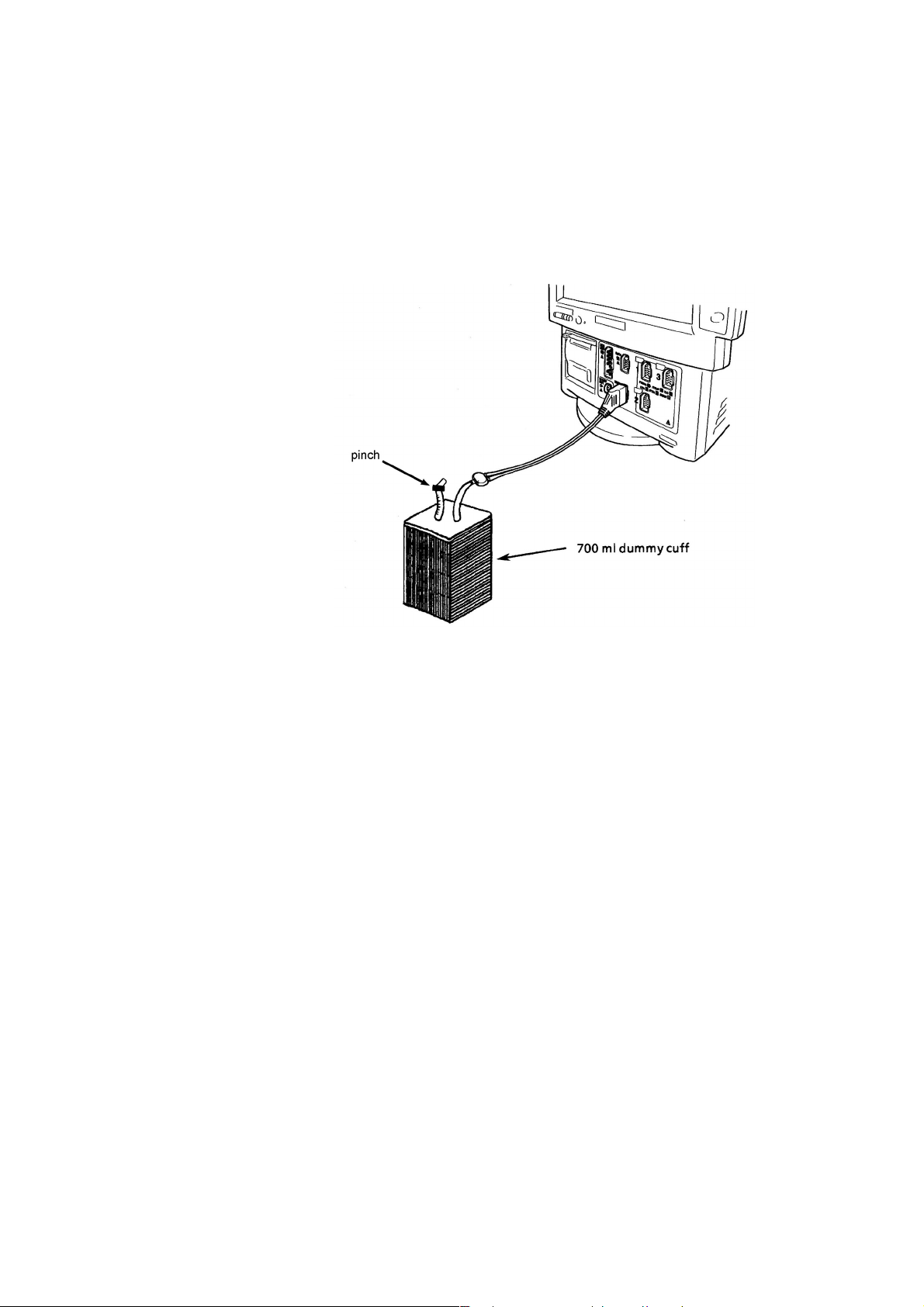
3. DIAGNOSTIC CHECK
4. Inflation Speed
This is used to check the inflation speed of the pressure pump. The specifications
state that the cuff pressure must be able to reach 250 mmHg in less than 7 seconds.
Checking the Inflation Speed
1. Connect the 700 ml dummy cuff to the instrument with the 3.5 m air hose as
shown below.
2. Touch the “SELECT” key to select item number 4.
3. Touch the “START” key to start the check.
If the inflation speed is less than 7 seconds, an “OK” message appears.
If an “ERROR” message appears, replace the NIBP Safety board or pneumatic
circuit with a new one.
3.36 Service Manual BSM-4100
Page 96

3. DIAGNOSTIC CHECK
5. Deflation Speed
NOTE
Skip this deflation speed check because it is covered in the “6. Step
Deflation” check.
This is used to check the deflation speed through the two solenoid valves (V1 and
V2) at different stages of pressure drop. An “OK” message is displayed if it takes
1.4 to 3.0 seconds for V1 and 2.5 to 4.3 seconds for V2. If not, an “ERROR”
message is displayed.
Checking the Deflation Speed
1. Connect the 700 ml dummy cuff to the instrument with the 3.5 m air hose as
shown below.
2. Touch the “SELECT” key to select item number 5.
3. Touch the “START” key to start the check.
If an “ERROR” message appears, replace the NIBP Safety board or pneumatic
circuit with a new one.
Service Manual BSM-4100 3.37
Page 97

3. DIAGNOSTIC CHECK
6. Step Deflation
This checks the step deflation of the cuff at given pressure.
HIGH pressure: Valve 1 opens for 40 ms and Valve 2 opens for 70 ms at 250 mmHg.
The “OK” message appears if the pressure drop is 5 to 20 mmHg.
LOW pressure: Valve 1 opens for 60 ms and Valve 2 opens for 80 ms at 20 mmHg.
The “OK” message appears if the pressure drop is 1 to 10 mmHg.
Checking the Step Deflation
1. Connect the 250 ml dummy cuff to the instrument with the 3.5 m air hose as
shown below.
2. Touch the “SELECT” key to select item number 6.
3. Touch the “START” key to start the check.
If an “ERROR” message appears, replace the NIBP Safety board or pneumatic
circuit with a new one.
3.38 Service Manual BSM-4100
Page 98

3. DIAGNOSTIC CHECK
7. Air Leak
This checks air leakage in the pneumatic circuit of NIBP module. In this check,
the air pressure of the dummy cuff goes up to 300 mmHg. It then compares the
pressure readings of the dummy cuff taken at 30 seconds and 90 seconds after the
pressure of the dummy cuff had reached 300 mmHg. If the pressure readings differ
by 5 mmHg or less, an “OK” message appears. If not, an “ERROR” message
appears. In this case, make sure that the cuff connector and internal air tubes are
firmly attached. If the “ERROR” message still appears, replace the NIBP Safety
board or pneumatic circuit with a new one.
Checking the Air Leak
1. Connect the 700 ml dummy cuff to the instrument with the 3.5 m air hose as
shown below.
2. Touch the “SELECT” key to select item number 7.
3. Touch the “START” key to start the check.
Service Manual BSM-4100 3.39
Page 99

3. DIAGNOSTIC CHECK
DPU ROM Check
This item checks the ROMs on the DPU board by the CRC (cyclic redundancy
check) technique. This check assigns a count number when one set of checks is
successfully completed.
If an error message appears, the DPU board will be faulty.
Procedure to Start and Exit the DPU ROM Check Program
1. To select the DPU ROM Check, touch the “ROM CHECK” key at the DPU
CHECK column.
2. The instrument repeats the check and increments the pass count until you
touch the “RETURN” key.
3. If the check program finds an error, it displays the “ERROR” message on the
screen.
4. To return to the MANUAL CHECK MENU screen at any time, touch the
“RETURN” key.
3.40 Service Manual BSM-4100
Page 100

3. DIAGNOSTIC CHECK
DPU RAM Check
This item checks the RAM on the DPU board by comparing the test patterns (first
written to the RAM) with the test patterns (later read from the RAM).
If an error message appears, the DPU board will be faulty.
Procedure to Start, Stop, and Exit the DPU RAM Check Program
1. To select the DPU RAM Check, touch the “RAM CHECK” key at the DPU
CHECK column. The check program automatically starts.
The “START” key is highlighted to indicate the process of checking.
2. If the check program finds an error, it displays the address, write data and read
data as above table.
3. To stop the check temporarily, touch the “STOP” key. The highlighted
“START” key changes to normal and the “STOP” key is highlighted.
To continue the check, touch the “START” key again.
4. To return to the MANUAL CHECK MENU screen, touch the “RETURN” key.
Service Manual BSM-4100 3.41
 Loading...