

Page 1
US-4000
ECHOSCAN
OPERATOR’S MANUAL
Page 2

NIDEK CO., LTD. : 34-14, Maehama, Hiroishi-cho, Gamagori, Aichi 443-0038, Japan
(Manufacturer) Telephone: (81-533) 67-6611
Facsimile: (81-533) 67-6610
NIDEK CO., LTD : 3F Sumitomo Fudosan Hongo Bldg., 3-22-5, Hongo,
(Tokyo Office) Bunkyo-Ku, Tokyo 113-0033, Japan
Telephone: (81-3) 5844-2641
Facsimile: (81-3) 5844-2642
NIDEK INCORPORATED : 47651 Westinghouse Drive, Fremont, California 94539, U. S. A.
(United States Agent) Telephone: (510) 226-5700
Facsimile: (510) 226-5750
Printed in JAPAN
June 2007
14610-P902A
Page 3
Use this device properly and safely.
BEFORE USE, READ THIS MANUAL.
This Operator’s Manual contains information necessary for the operation of the NIDEK
US-4000 ECHOSCAN. This manual includes the operating procedures, safety
precautions, and specifications.
IEC standards are applied in this manual.
The safety precautions and operating procedures must be thoroughly understood prior
to operation of the device. Keep this manual handy for reference.
:
Use of the device is limited to ophthalmologists or personnel involved in medical practice
under the ophthalmologists’ instructions in accordance with the instructions in the
operator’s manual. The ophthalmologists are responsible for other applications of this
device.
Use of the device outside the scope of this maual may cause unexpected troubles and
adverse events.
If you encounter any problems or have questions about the device, please contact NIDEK
or your authorized distributor.
Safety precautions
In this manual, signal words are used to designate the degree or level of safety alerting. The definitions are as follows.
CAUTION
• Indicates a potentially hazardous situation which, if not avoided, may result in minor or
moderate injury or property damage accident.
Even situations indicated by “ CAUTION” may result in serious injury under certain conditions.
Safety precautions must be strictly followed at all times.
I
Page 4

:
Use precautions
Before Use
CAUTION
• Never use the device for other than its intended purpose.
NIDEK will assume no responsibility for accident or malfunction caused by improper use.
• The safety precautions and operating procedures must be thoroughly understood
prior to operation of the device.
Use of the device outside the scope of this maual may cause unexpected troubles
and adverse events.
• Do not use the deviec if any abnormality is found in the visual check or operation
check before use.
If there is any abnormality in power output, communication, or operation, the device
may become unusable.
Intended effect cannot be obtained with a failured device and unexpected health
hazard may result from unexpected troubles and misdiagnosis.
• Never modify nor touch the internal structure of the device.
Electric shock or malfunction may result.
• Install the device in an environment that meets the following conditions. The
following conditions must be maintained during use.
Use conditions
Ambient temperature: +10ºC to +35ºC
Humidity: 30 to 75% (Non-condensing)
Atmospheric pressure: 800 hPa to 1060 hPa
Minimal dust in the air
Little influence of disturbance light
Level and stable surface free from vibration and bumping
If the device is not installed and used under the above conditions, the reliability of
measurement results is lowered, and malfunction may result. In addition, injury may
result if the device is bumped or falls down.
• Install the device in an environment where no contaminants such as corrosive
gas, acid, and salt are contained in the air.
Corrosion or malfunction of the device may result.
• Avoid installing the device where it is exposed to direct air flow from an air
conditioner.
Changes in temperature may result in condensation inside the device or adversely
affect measurement results.
• Be sure to use a power outlet which meets power requirements.
If the supplied voltage is too high or low, the device may not deliver full performance, and malfunction or fire may result.
• The power outlet must be equipped with a grounding terminal. If not, connect the
device to the protective earth ground using a ground conductor.
Electric shock or fire may result from current leakage caused by malfunction.
• Insert the mains plug into an outlet as far as the prongs of the plug will go.
Imperfect connection may result in fire.
II
Page 5

:
CAUTION
• For supplying the device with the power, never use a table tap or an extension
cable.
There is a fear of reduction in electrical safety.
• Never use any power cord other than the speficied one or use the accessory power
cord for other instruments.
Malfunction or fire may result.
• Never crush or pinch the power cord with heavy objects.
Damage may result in electric shock or fire.
• Before connecting cables to the device, turn the device off and disconnect the
power cord from an outlet.
Malfunction may result.
• Before transporting the device, pack the device in the specified packing materials
to avoid impact from falling or other causes.
Excessive vibration and impact to the device may result in device failure.
Installation precautions
CAUTION
• In installation, be sure that the following conditions are satisfied:
- Protected form direct sunlight or ultraviolet rays
- Not exposed to rain or water
- Dust free environment with air containing no sulfur or salt
- Level and stable surface free form vibration and bumping
- The specified environmental conditions during use are satisfied
• Install the US-4000 in a place where there is no other devices such as laser
devices that radiate strong electromagnetic waves.
Strong electromagnetic waves may interfere with proper measurement.
If the US-4000 must be installed in the same place as any other device that radiates
strong electromagnetic waves, perform the measurement using the US-4000 after
stopping operation of the other device.
During Use
CAUTION
• Install the device so that the air vent on the cover of the main body is not blocked.
• Do not use this device in an operating room.
• Do not use the deviec if any abnormality is found in the visual check or operation
check before use.
Intended effect cannot be obtained with a failured device and unexpected health
hazard may result from unexpected troubles and misdiagnosis.
III
Page 6

:
CAUTION
• In the event that a strange odor or smoke is noticed coming from the device, turn it
off and unplug the power cord immediately. After confirming that the smoke is no
longer being produced, contact NIDEK or your authorized distributor.
Continued use may result in electric shock or fire. In case of fire, use a dry chemical
(ABC) extinguisher.
• If the internal wires of the power cord are exposed, power to the device is
interrupted by moving the cord, or the plug or cord becomes extremely hot, this
indicates that the cord is damaged. Immediately replace the power cord.
Immediately remove the plug from the outlet and contact NIDEK or your authorized
distributor for replacement; otherwise, electric shock or fire may result.
• Never press the LCD screen with a hard object such as a ball-point pen. Keep
magnetic objects away from the LCD screen.
Malfunction may result.
• Do not operate the LCD screen with wet hands.
Water intrusion may result in malfunction of the device.
• There may be a few “constantly-lit”, “missing” or “dead” pixels in your LCD screen
which are a characteristic of the LCD screens, This does not represent a failure of
the LCD screen; continuously use the monitor.
• Do not use cables and accessories that are not specified for the device.
The electromagnetic compatibility (EMC) may be decreased and the device operation
may be affacted.
• Do not use the device near portable and mobile radio frequency communication
systems.
They may have an adverse effect on operation of the device.
• Do not use the device in the same room with other equipment such as life-support
equipment, other equipment that has major affects on the life of the patient and
results of treatment, or other measurement or treatment equipment that involves
small electric current.
• If the instrument is connected to a PC that does not comply with IEC60601-1 (except
one that uses an AC adapter that meets the Class II requirements of IEC60950-1),
supply power to the instrument and PC through isolation transformers.
Contact NIDEK or your authorized distributor for installing isolation transformers.
• Perform the measurements using appropriate sonic velocity values.
Accurate axial length and pachymetry cannot be obtained with inappropriate sonic
velocity values.
• This device uses a heat-sensitive printer paper. To keep the printed data for a long
period of time, make copies of the printouts.
The paper degrades over time and the printed data may become illegible.
IV
Page 7

Probe
:
CAUTION
• Always hold the plug, not the cable, when connecting or disconnecting the probe.
If the cable breaks near the probe side, it is necessary to replace the whole probe.
• Disinfect the probe tip for every patient.
Failure to do so may cause infection of patient’s cornea.
• Before measurement, confirm that there are no scratches, chips, or cracks on the
surface of the probe tip.
If there are, proper measurement may not be possible.
• Before measurement, confirm that there are no scratches or chips on the surface of
the probe tip which contacts the cornea.
If there are, the cornea may be damaged.
• Pay attention not to bump the probe tip.
The probe tip may be deformed or chipped.
• Do not press the probe against the patient’s cornea with excessive force.
The measurement result becomes unstable and the patient’s eye may be damaged.
• After using the probe, put the protective cover on the probe and keep it in the case.
• Do not move the probe while it is in contact with the patient’s cornea.
The corneal epithelium may become damaged.
• Never perform autoclaving, EOG sterilization, or ultrasonic cleaning of the A-scan,
B-scan, or Pachymetry probe.
The probes may become damaged.
V
Page 8

:
After use
CAUTION
• When the device is not in use, turn off power to it and place the dust cover over it.
Dust may affect the accuracy of measurements.
• Always hold the power plug, not the cord, to remove it from an outlet.
The metal core of the cord may be damaged and electric shock, malfunction, or fire
may result.
• Wipe between the prongs of the power plug periodically.
Dust that may settle between the prongs attracts moisture and could result in short
circuit, electric shock, or fire.
• If the device will not be used for a long period of time, disconnect the power cord
from the power outlet .
Fire may result.
• Maintain the surrounding temperature and humidity at the following ranges during
transportation and storage of the device.
Environmental conditions:
Ambient temperature: –10ºC to +55ºC
Humidity: 10 to 95% (non-condensing)
Minimal dust in the air
Protected from direct sunlight
• To transport the device, use the packing materials in which the device was
delivered to protect it from excessive vibration and bumping.
Excessive vibration or bumping may result in device failure.
VI
Page 9

Maintenance and checks
:
CAUTION
• Only service personnel properly trained by Nidek are allowed to service the device.
Nidek assumes no responsibility for accidents resulting from improper servicing.
• When performing maintenance work, secure a sufficient maintenance space.
Maintenance work in an insufficient space may result in injury.
• When the device is sent back to NIDEK for repair or maintenance, wipe the surfaces
(especially, the parts that come into contact with the patients) of the device with a
clean cloth soaked with ethyl alcohol for disinfection.
• Each time the system starts, be sure to make a check of the device.
If not, accurate measurement values cannot be obtained.
• When replacing the printer paper, use the specified type.
Failure to do so may cause a malfunction of the printer.
• When replacing fuses, use the specified ones.
Failure to do so may cause a malfunction or a fire.
• When cleaning the cover of the device and touch screen, never use organic
solvents such as thinners or abrasive detergents.
The cover of the device and touch screen may be damaged.
• If the LCD screen becomes dirty, wipe it with a soft cloth or gauze soaked in with
ethanol.
Other cleaning methods may damage the touch screen.
After the cleaning, when the accessories are dry, be sure to visually check their exterior.
Disposal
CAUTION
• Only service personnel properly trained by NIDEK are allowed to disassemble and
repair the device.
NIDEK assumes no responsibility for accidents caused by improper repair.
• Follow local governing ordinances and recycling plans regarding disposal or
recycling of device components.
It is recommended to commission the disposal to a designated industrial waste disposal contractor.
• When disposing of packing materials, sort them by material and follow local
governing ordinances and recycling plans.
VII
Page 10

:
Patient environment
The patient environment is the volume of space in which contact can occur between the patient and
any part of the device or between the patient and any other person(s) touching the device.
Use devices that comply with IEC6060-1 in the patient environment. If any device that does not
comply with IEC 60601-1 is to be used, use an isolating transformer or common protective grounding.
Radius of 1.5 m
VIII
1.5 m
2.5 m
1.5 m
Page 11

Table of Contents
1. BEFORE USE . . . . . . . . . . . . . . . . . . . . . . . . . . . . . . . . . . . 1
1.1 Outline of Device . . . . . . . . . . . . . . . . . . . . . . . . . . . . . . . . . . . . . . . . . . . . . . . . . . . . . . .1
1.2 Indications for Use . . . . . . . . . . . . . . . . . . . . . . . . . . . . . . . . . . . . . . . . . . . . . . . . . . . . .1
1.3 Principles . . . . . . . . . . . . . . . . . . . . . . . . . . . . . . . . . . . . . . . . . . . . . . . . . . . . . . . . . . . . . .2
1.4 Device Description . . . . . . . . . . . . . . . . . . . . . . . . . . . . . . . . . . . . . . . . . . . . . . . . . . . . .3
{ Front view . . . . . . . . . . . . . . . . . . . . . . . . . . . . . . . . . . . . . . . . . . . . . . . . . . . . . .3
{ Rear view . . . . . . . . . . . . . . . . . . . . . . . . . . . . . . . . . . . . . . . . . . . . . . . . . . . . . . .4
1.5 Screen Description . . . . . . . . . . . . . . . . . . . . . . . . . . . . . . . . . . . . . . . . . . . . . . . . . . . . .8
1.5.1 A-scan biometry screen . . . . . . . . . . . . . . . . . . . . . . . . . . . . . . . . . . . . . . . . . . . . . .8
1.5.2 IOL power calculation screen . . . . . . . . . . . . . . . . . . . . . . . . . . . . . . . . . . . . . . . . .11
1.5.3 A-scan biometry utility screen . . . . . . . . . . . . . . . . . . . . . . . . . . . . . . . . . . . . . . . . .13
1.5.4 B-scan imaging screen . . . . . . . . . . . . . . . . . . . . . . . . . . . . . . . . . . . . . . . . . . . . . .15
1.5.5 B-scan imaging utility screen . . . . . . . . . . . . . . . . . . . . . . . . . . . . . . . . . . . . . . . . .17
1.5.6 Pachymetry screen . . . . . . . . . . . . . . . . . . . . . . . . . . . . . . . . . . . . . . . . . . . . . . . . .19
1.5.7 Pachymetry utility screen . . . . . . . . . . . . . . . . . . . . . . . . . . . . . . . . . . . . . . . . . . . .21
1.5.8 Utility screen (1/2) . . . . . . . . . . . . . . . . . . . . . . . . . . . . . . . . . . . . . . . . . . . . . . . . . .23
1.5.9 Utility screen (2/2) . . . . . . . . . . . . . . . . . . . . . . . . . . . . . . . . . . . . . . . . . . . . . . . . . .25
1.6 Labels and Indications on the Device . . . . . . . . . . . . . . . . . . . . . . . . . . . . . . . . . . .26
1.7 Checking Contents . . . . . . . . . . . . . . . . . . . . . . . . . . . . . . . . . . . . . . . . . . . . . . . . . . . .28
2. OPERATING PROCEDURES . . . . . . . . . . . . . . . . . . . . . . 29
2.1 Operation flow . . . . . . . . . . . . . . . . . . . . . . . . . . . . . . . . . . . . . . . . . . . . . . . . . . . . . . . .29
2.2 Device Setup. . . . . . . . . . . . . . . . . . . . . . . . . . . . . . . . . . . . . . . . . . . . . . . . . . . . . . . . . .32
2.2.1 Connecting power cord . . . . . . . . . . . . . . . . . . . . . . . . . . . . . . . . . . . . . . . . . . . . . .32
2.2.2 Connecting foot switch . . . . . . . . . . . . . . . . . . . . . . . . . . . . . . . . . . . . . . . . . . . . . .33
2.2.3 Attaching probe rest . . . . . . . . . . . . . . . . . . . . . . . . . . . . . . . . . . . . . . . . . . . . . . . .33
2.2.4 Connecting probe . . . . . . . . . . . . . . . . . . . . . . . . . . . . . . . . . . . . . . . . . . . . . . . . . .34
{ A-scan probe . . . . . . . . . . . . . . . . . . . . . . . . . . . . . . . . . . . . . . . . . . . . . . . . . . .34
{ Connecting B-scan probe . . . . . . . . . . . . . . . . . . . . . . . . . . . . . . . . . . . . . . . . .35
{ Connecting Pachymetry probe. . . . . . . . . . . . . . . . . . . . . . . . . . . . . . . . . . . . . .35
2.2.5 Connecting Probe stand (optional) . . . . . . . . . . . . . . . . . . . . . . . . . . . . . . . . . . . . .36
{ Attaching A-scan probe . . . . . . . . . . . . . . . . . . . . . . . . . . . . . . . . . . . . . . . . . . .36
{ Attaching cable for fixation lamp . . . . . . . . . . . . . . . . . . . . . . . . . . . . . . . . . . . .36
2.3 Preparation . . . . . . . . . . . . . . . . . . . . . . . . . . . . . . . . . . . . . . . . . . . . . . . . . . . . . . . . . . .37
2.3.1 Adding new patient data . . . . . . . . . . . . . . . . . . . . . . . . . . . . . . . . . . . . . . . . . . . . .39
2.3.2 Setting physician data . . . . . . . . . . . . . . . . . . . . . . . . . . . . . . . . . . . . . . . . . . . . . . .41
2.4 A-scan Biometry. . . . . . . . . . . . . . . . . . . . . . . . . . . . . . . . . . . . . . . . . . . . . . . . . . . . . . .44
2.4.1 Basic operation of A-scan biometry . . . . . . . . . . . . . . . . . . . . . . . . . . . . . . . . . . . .44
2.4.2 Cautions in A-scan biometry . . . . . . . . . . . . . . . . . . . . . . . . . . . . . . . . . . . . . . . . . .50
2.4.3 Manual gate . . . . . . . . . . . . . . . . . . . . . . . . . . . . . . . . . . . . . . . . . . . . . . . . . . . . . .51
2.4.4 Calculation of IOL refractive power . . . . . . . . . . . . . . . . . . . . . . . . . . . . . . . . . . . . .53
IX
Page 12

:
2.4.5 Comparison in DUAL screen . . . . . . . . . . . . . . . . . . . . . . . . . . . . . . . . . . . . . . . . . 56
2.4.6 Setting A-scan biometry utility . . . . . . . . . . . . . . . . . . . . . . . . . . . . . . . . . . . . . . . . 58
{ Changing sonic velocity to calculate distance . . . . . . . . . . . . . . . . . . . . . . . . . . 58
{ Setting IOL formula . . . . . . . . . . . . . . . . . . . . . . . . . . . . . . . . . . . . . . . . . . . . . . 60
{ Setting normally used IOL . . . . . . . . . . . . . . . . . . . . . . . . . . . . . . . . . . . . . . . . . 61
{ Setting fixation light ON/OFF. . . . . . . . . . . . . . . . . . . . . . . . . . . . . . . . . . . . . . . 62
{ Setting print format . . . . . . . . . . . . . . . . . . . . . . . . . . . . . . . . . . . . . . . . . . . . . . 63
{ Inputting IOL data . . . . . . . . . . . . . . . . . . . . . . . . . . . . . . . . . . . . . . . . . . . . . . . 64
{ Calculating personal value . . . . . . . . . . . . . . . . . . . . . . . . . . . . . . . . . . . . . . . . 66
{ Setting IOL power calculation formula in specified axial length range . . . . . . . 69
2.5 B-scan Imaging . . . . . . . . . . . . . . . . . . . . . . . . . . . . . . . . . . . . . . . . . . . . . . . . . . . . . . . 71
2.5.1 Basic operation of B-scan imaging . . . . . . . . . . . . . . . . . . . . . . . . . . . . . . . . . . . . . 71
2.5.2 Probe angle . . . . . . . . . . . . . . . . . . . . . . . . . . . . . . . . . . . . . . . . . . . . . . . . . . . . . . 73
2.5.3 Changing observation depth. . . . . . . . . . . . . . . . . . . . . . . . . . . . . . . . . . . . . . . . . . 73
2.5.4 Changing display range . . . . . . . . . . . . . . . . . . . . . . . . . . . . . . . . . . . . . . . . . . . . . 74
2.5.5 CV mode . . . . . . . . . . . . . . . . . . . . . . . . . . . . . . . . . . . . . . . . . . . . . . . . . . . . . . . . 76
2.5.6 Zoom . . . . . . . . . . . . . . . . . . . . . . . . . . . . . . . . . . . . . . . . . . . . . . . . . . . . . . . . . . . 77
2.5.7 Four image display . . . . . . . . . . . . . . . . . . . . . . . . . . . . . . . . . . . . . . . . . . . . . . . . . 79
2.5.8 Measuring area on B-scan imaging screen (Area screen) . . . . . . . . . . . . . . . . . . . 81
2.5.9 Measuring distance on B-scan image (Caliper screen) . . . . . . . . . . . . . . . . . . . . . 83
2.5.10 Moving image operation . . . . . . . . . . . . . . . . . . . . . . . . . . . . . . . . . . . . . . . . . . . . . 85
2.5.11 Setting B-scan imaging utility . . . . . . . . . . . . . . . . . . . . . . . . . . . . . . . . . . . . . . . . . 86
{ Setting probe angle . . . . . . . . . . . . . . . . . . . . . . . . . . . . . . . . . . . . . . . . . . . . . . 86
{ Setting scan depth. . . . . . . . . . . . . . . . . . . . . . . . . . . . . . . . . . . . . . . . . . . . . . . 87
{ Setting scale color . . . . . . . . . . . . . . . . . . . . . . . . . . . . . . . . . . . . . . . . . . . . . . . 87
{ Changing gain curve pattern . . . . . . . . . . . . . . . . . . . . . . . . . . . . . . . . . . . . . . . 88
{ Setting Log scale range. . . . . . . . . . . . . . . . . . . . . . . . . . . . . . . . . . . . . . . . . . . 89
{ Setting printer mode . . . . . . . . . . . . . . . . . . . . . . . . . . . . . . . . . . . . . . . . . . . . . 89
{ Setting data format . . . . . . . . . . . . . . . . . . . . . . . . . . . . . . . . . . . . . . . . . . . . . . 90
{ Other settings . . . . . . . . . . . . . . . . . . . . . . . . . . . . . . . . . . . . . . . . . . . . . . . . . . 90
2.6 Pachymetry. . . . . . . . . . . . . . . . . . . . . . . . . . . . . . . . . . . . . . . . . . . . . . . . . . . . . . . . . . . 91
2.6.1 Basic operation of pachymetry . . . . . . . . . . . . . . . . . . . . . . . . . . . . . . . . . . . . . . . . 91
2.6.2 Setting pachymetry utility . . . . . . . . . . . . . . . . . . . . . . . . . . . . . . . . . . . . . . . . . . . . 95
{ Setting Pachymetry probe . . . . . . . . . . . . . . . . . . . . . . . . . . . . . . . . . . . . . . . . . 95
{ Setting PRINT switch of foot switch . . . . . . . . . . . . . . . . . . . . . . . . . . . . . . . . . 96
{ Setting printing of pachymetry results . . . . . . . . . . . . . . . . . . . . . . . . . . . . . . . . 96
{ Setting corneal thickness sonic velocity to calculate distance . . . . . . . . . . . . . 97
{ Setting map selected at device power-up . . . . . . . . . . . . . . . . . . . . . . . . . . . . . 97
2.7 UTILITY . . . . . . . . . . . . . . . . . . . . . . . . . . . . . . . . . . . . . . . . . . . . . . . . . . . . . . . . . . . . . . 98
2.7.1 Displaying Utility screen . . . . . . . . . . . . . . . . . . . . . . . . . . . . . . . . . . . . . . . . . . . . . 98
2.7.2 Setting Utility (1/2) . . . . . . . . . . . . . . . . . . . . . . . . . . . . . . . . . . . . . . . . . . . . . . . . 100
{ Setting backlight . . . . . . . . . . . . . . . . . . . . . . . . . . . . . . . . . . . . . . . . . . . . . . . 100
{ Setting Start Mode. . . . . . . . . . . . . . . . . . . . . . . . . . . . . . . . . . . . . . . . . . . . . . 100
{ Setting Communication . . . . . . . . . . . . . . . . . . . . . . . . . . . . . . . . . . . . . . . . . . 101
{ Setting date and time indication format . . . . . . . . . . . . . . . . . . . . . . . . . . . . . . 101
{ Setting Auto OFF. . . . . . . . . . . . . . . . . . . . . . . . . . . . . . . . . . . . . . . . . . . . . . . 102
{ Setting sound volume . . . . . . . . . . . . . . . . . . . . . . . . . . . . . . . . . . . . . . . . . . . 102
{ Setting save mode. . . . . . . . . . . . . . . . . . . . . . . . . . . . . . . . . . . . . . . . . . . . . . 103
2.7.3 Setting Utility(2/2) . . . . . . . . . . . . . . . . . . . . . . . . . . . . . . . . . . . . . . . . . . . . . . . . . 107
{ Adjusting touch screen . . . . . . . . . . . . . . . . . . . . . . . . . . . . . . . . . . . . . . . . . . 107
{ Setting date and time . . . . . . . . . . . . . . . . . . . . . . . . . . . . . . . . . . . . . . . . . . . 107
X
Page 13

{ Handling EEPROM parameters . . . . . . . . . . . . . . . . . . . . . . . . . . . . . . . . . . . 108
2.8 Completion of Operation. . . . . . . . . . . . . . . . . . . . . . . . . . . . . . . . . . . . . . . . . . . . . . 109
3.
OPERATION WHEN PERIPHERAL DEVICES ARE CONNECTED
. . 111
3.1 Connecting to Keratometer . . . . . . . . . . . . . . . . . . . . . . . . . . . . . . . . . . . . . . . . . . . 111
3.1.1 Outline . . . . . . . . . . . . . . . . . . . . . . . . . . . . . . . . . . . . . . . . . . . . . . . . . . . . . . . . . 111
3.1.2 Method of connection (example) . . . . . . . . . . . . . . . . . . . . . . . . . . . . . . . . . . . . . 111
3.1.3 Operating procedure. . . . . . . . . . . . . . . . . . . . . . . . . . . . . . . . . . . . . . . . . . . . . . . 112
3.2 Connecting to Video Printer . . . . . . . . . . . . . . . . . . . . . . . . . . . . . . . . . . . . . . . . . . . 112
3.3 Connecting to USB Port . . . . . . . . . . . . . . . . . . . . . . . . . . . . . . . . . . . . . . . . . . . . . . 113
3.4 Connecting to LAN Port . . . . . . . . . . . . . . . . . . . . . . . . . . . . . . . . . . . . . . . . . . . . . . 114
4. CHECKS . . . . . . . . . . . . . . . . . . . . . . . . . . . . . . . . . . . . . 117
:
4.1 Checks Before Use. . . . . . . . . . . . . . . . . . . . . . . . . . . . . . . . . . . . . . . . . . . . . . . . . . . 117
4.2 Usage of the Test Piece . . . . . . . . . . . . . . . . . . . . . . . . . . . . . . . . . . . . . . . . . . . . . . 118
4.2.1 Usage of test piece for A-scan biometry. . . . . . . . . . . . . . . . . . . . . . . . . . . . . . . . 118
4.2.2 Usage of test piece for pachymetry . . . . . . . . . . . . . . . . . . . . . . . . . . . . . . . . . . . 119
4.3 Check List . . . . . . . . . . . . . . . . . . . . . . . . . . . . . . . . . . . . . . . . . . . . . . . . . . . . . . . . . . . 121
5. MAINTENANCE . . . . . . . . . . . . . . . . . . . . . . . . . . . . . . . 123
5.1 Troubleshooting. . . . . . . . . . . . . . . . . . . . . . . . . . . . . . . . . . . . . . . . . . . . . . . . . . . . . . 123
5.2 Various error codes and Suggested Actions . . . . . . . . . . . . . . . . . . . . . . . . . . . 124
5.3 Replacing Printer Paper . . . . . . . . . . . . . . . . . . . . . . . . . . . . . . . . . . . . . . . . . . . . . . 128
5.4 Replacing Fuses . . . . . . . . . . . . . . . . . . . . . . . . . . . . . . . . . . . . . . . . . . . . . . . . . . . . . 130
5.5 Cleaning. . . . . . . . . . . . . . . . . . . . . . . . . . . . . . . . . . . . . . . . . . . . . . . . . . . . . . . . . . . . . 131
5.5.1 Cleaning cover . . . . . . . . . . . . . . . . . . . . . . . . . . . . . . . . . . . . . . . . . . . . . . . . . . . 131
5.5.2 Cleaning printer . . . . . . . . . . . . . . . . . . . . . . . . . . . . . . . . . . . . . . . . . . . . . . . . . . 131
5.5.3 Cleaning touch screen . . . . . . . . . . . . . . . . . . . . . . . . . . . . . . . . . . . . . . . . . . . . . 132
5.6 Maintenance of Ultrasound Probe . . . . . . . . . . . . . . . . . . . . . . . . . . . . . . . . . . . . . 133
5.6.1 Cleaning ultrasound probe . . . . . . . . . . . . . . . . . . . . . . . . . . . . . . . . . . . . . . . . . . 133
5.6.2 Disinfecting ultrasound probe . . . . . . . . . . . . . . . . . . . . . . . . . . . . . . . . . . . . . . . . 134
5.6.3 Sterilizing ultrasound probe . . . . . . . . . . . . . . . . . . . . . . . . . . . . . . . . . . . . . . . . . 135
5.7 List of Replacement Parts . . . . . . . . . . . . . . . . . . . . . . . . . . . . . . . . . . . . . . . . . . . . 136
6. SPECIFICATIONS AND CONFIGURATION . . . . . . . . . 137
6.1 Classifications . . . . . . . . . . . . . . . . . . . . . . . . . . . . . . . . . . . . . . . . . . . . . . . . . . . . . . . 137
XI
Page 14

:
6.2 Specifications . . . . . . . . . . . . . . . . . . . . . . . . . . . . . . . . . . . . . . . . . . . . . . . . . . . . . . . . 138
6.2.1 A-scan biometry/IOL power calculation . . . . . . . . . . . . . . . . . . . . . . . . . . . . . . . . 138
6.2.2 B-scan imaging. . . . . . . . . . . . . . . . . . . . . . . . . . . . . . . . . . . . . . . . . . . . . . . . . . . 139
6.2.3 Pachymetry. . . . . . . . . . . . . . . . . . . . . . . . . . . . . . . . . . . . . . . . . . . . . . . . . . . . . . 139
6.2.4 Other functions . . . . . . . . . . . . . . . . . . . . . . . . . . . . . . . . . . . . . . . . . . . . . . . . . . . 139
6.2.5 Dimensions and weight . . . . . . . . . . . . . . . . . . . . . . . . . . . . . . . . . . . . . . . . . . . . 140
6.2.6 Environemntal conditions (during use) . . . . . . . . . . . . . . . . . . . . . . . . . . . . . . . . . 140
6.2.7 Environmental conditions (during storage and shipping) . . . . . . . . . . . . . . . . . . . 140
6.2.8 Composition of parts that come into contact with human body . . . . . . . . . . . . . . 140
6.2.9 Others. . . . . . . . . . . . . . . . . . . . . . . . . . . . . . . . . . . . . . . . . . . . . . . . . . . . . . . . . . 140
6.3 Configuration . . . . . . . . . . . . . . . . . . . . . . . . . . . . . . . . . . . . . . . . . . . . . . . . . . . . . . . . 141
6.3.1 Standard accessories . . . . . . . . . . . . . . . . . . . . . . . . . . . . . . . . . . . . . . . . . . . . . . 141
6.3.2 Optional accessories . . . . . . . . . . . . . . . . . . . . . . . . . . . . . . . . . . . . . . . . . . . . . . 141
7. IOL FORMULA . . . . . . . . . . . . . . . . . . . . . . . . . . . . . . . . 143
7.1 Outline of IOL Formula . . . . . . . . . . . . . . . . . . . . . . . . . . . . . . . . . . . . . . . . . . . . . . . 143
7.1.1 SRK Formula . . . . . . . . . . . . . . . . . . . . . . . . . . . . . . . . . . . . . . . . . . . . . . . . . . . . 143
7.1.2 SRK II Formula. . . . . . . . . . . . . . . . . . . . . . . . . . . . . . . . . . . . . . . . . . . . . . . . . . . 144
7.1.3 SRK/T Formula . . . . . . . . . . . . . . . . . . . . . . . . . . . . . . . . . . . . . . . . . . . . . . . . . . . 146
7.1.4 Binkhorst Formula . . . . . . . . . . . . . . . . . . . . . . . . . . . . . . . . . . . . . . . . . . . . . . . . 147
7.1.5 Hoffer Q Formula . . . . . . . . . . . . . . . . . . . . . . . . . . . . . . . . . . . . . . . . . . . . . . . . . 148
7.1.6 Holladay Formula . . . . . . . . . . . . . . . . . . . . . . . . . . . . . . . . . . . . . . . . . . . . . . . . . 149
8. EMC & Acoustic output. . . . . . . . . . . . . . . . . . . . . . . . . 151
8.1 EMC (ELECTROMAGNETIC COMPATIBILITY). . . . . . . . . . . . . . . . . . . . . . . . 151
8.2 Acoustic output reporting table(IEC 60601-2-37:2005) . . . . . . . . . . . . . . . . . . 156
8.2.1 A-scan probe . . . . . . . . . . . . . . . . . . . . . . . . . . . . . . . . . . . . . . . . . . . . . . . . . . . . 156
8.2.2 B-scan probe . . . . . . . . . . . . . . . . . . . . . . . . . . . . . . . . . . . . . . . . . . . . . . . . . . . . 157
8.2.3 45× angled probe with detachable tip. . . . . . . . . . . . . . . . . . . . . . . . . . . . . . . . . . 158
8.2.4 45× angled Probe . . . . . . . . . . . . . . . . . . . . . . . . . . . . . . . . . . . . . . . . . . . . . . . . . 159
8.2.5 Pachymetry probe . . . . . . . . . . . . . . . . . . . . . . . . . . . . . . . . . . . . . . . . . . . . . . . . 160
8.2.6 GLOBAL ACOUSTIC OUTPUT LIMITS . . . . . . . . . . . . . . . . . . . . . . . . . . . . . . . . 161
9. Glossary . . . . . . . . . . . . . . . . . . . . . . . . . . . . . . . . . . . . . 163
XII
Page 15

1.
BEFORE USE
1.1 Outline of Device
The NIDEK US-4000 Echoscan is an ultrasonic device to visualize the shape and properties of the
eye interior and provide the image information to be used for diagnosis. It also measures the axial
length and corneal thickness and provides the information to be used for diagnosis.
Axial length is one of the parameters used to determine the refractive power of an IOL prior to cataract
surgery. By inputting the measured axial length with other parameters, the refractive power of an IOL
can be calculated.
Corneal thickness is a necessary parameter when considering the clinical influence of surgery, drugs
and contact lenses upon endothelium tissue. Pachymetry is now commonly performed prior to and
after corneal refractive surgery using devices such as the excimer laser.
1
The US-4000 is comprised of a touch screen, main body with a built-in printer, an A-scan probe, a B-
scan probe, a Pachymetry probe, and a foot switch. Items such as a video printer are also available
as optional accessories.
1.2 Indications for Use
The NIDEK US-4000 Echoscan is a medical device used for measuring the axial length, anterior
chamber depth, corneal thickness, lens thickness, and vitreous body thickess, for calculating IOL
power, and for observing the interior of the eye in B-scan imaging.
1
Page 16

BEFORE USE: Principles
1.3 Principles
Ultrasonic waves are the sound waves pitched above the range of human hearing whose frequency is
20,000 Hz or more. In the medical field, ultrasonic waves of frequencies between 1 and 15 MHz are
applied, and these types of high sound waves have the following characteristics similar to light:
They have a high tendency to travel in a straight direction.
They have characteristics such as reflection and refraction at the boundaries of media which
have different acoustic impedances.
(Acoustic impedance = Density of medium × Sonic velocity in the medium)
Special material is adopted to transmit and receive the ultrasonic pulses. Electrodes are placed on
both sides of a thin piece of material, and the thickness of the material is changed by the fluctuation of
voltage when a voltage is applied between them. The material vibrates with its inherent frequency
when voltage is applied, and transmits the ultrasonic pulses. Conversely, when this material vibrates
by the impact of the ultrasonic pulses, voltage of the same frequency is generated on both electrodes
and it becomes possible to register the ultrasonic pulses as electrical signals. This phenomena is
called the “Piezo effect”, and the converter, which electrically generates the ultrasound waves and
changes them into voltage, is called a transducer.
In A-scan biometry, the ultrasonic pulse travels inside the eye when the probe is put on the eyeball. A
portion of the pulses is reflected from the boundary of the cornea, anterior chamber, lens, vitreous
body and retina, and their echoes are received at the same probe. The received echoes are converted
to the electronic acoustic signals and indicated on the LCD as an amplitude. In addition, the time dif-
ference of each echo is measured and the size of each area of tissue (anterior chamber depth, lens
thickness, vitreous body length and axial length) is calculated according to the time difference and
known inherent sonic velocity through each kind of tissue.
In B-scan imaging, touching the mechanical sector scan probe with a built-in transducer to the eye
emits the ultrasonic pulses that travel inside the eye. These pulses are reflected at boundaries of the
cornea, anterior chamber, anterior chamber, crystalline lens, vitreous body, and retina. The reflected
pulses (echoes) are received by the same mechanical sector scan probe to be converted to electrical
signals. Then the amplitude of the electrical signals is converted to brightness to display the two-
dimensional static and dynamic images of the eye interior on the screen.
In pachymetry, the ultrasonic pulses are transmitted when the probe is put on the cornea. A part of the
pulses is reflected at the front and rear surface of the cornea. When the probe receives the reflected
echoes, the time difference of each echo is measured and the corneal thickness is calculated accord-
ing to the time difference and known inherent sonic velocity through the cornea.
If the directions of the ultrasonic waves are not perpendicular to each boundary surface in both axial
length and pachymetry, the echoes become weak and may not return to the probe. Therefore, it is
very important to coincide the direction of the ultrasonic wave with the visual axis in order to achieve
accurate measurement.
2
Page 17
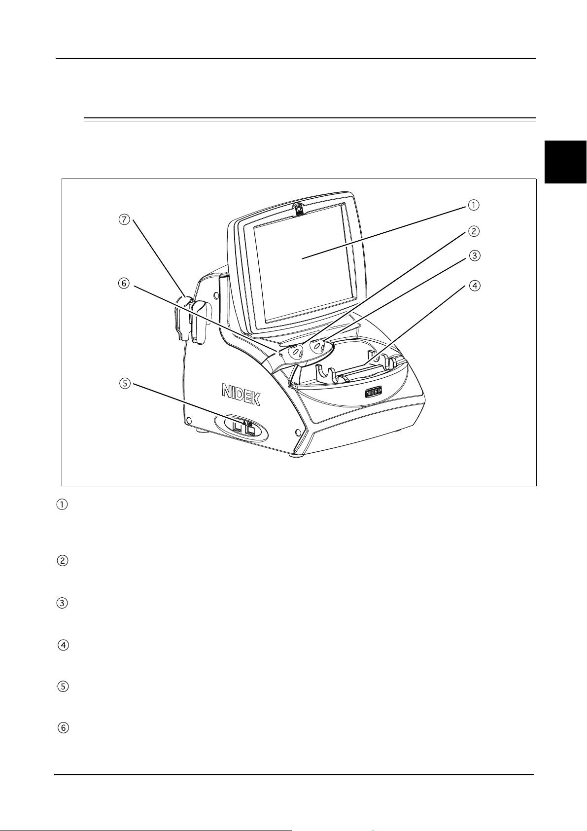
1.4 Device Description
{ Front view
BEFORE USE: Device Description
1
LCD touch screen
A 8.4-inch color LCD that is used as a touch screen for data input.
The LCD touch screen can be tilted for the operator's convenience.
Knob 1
Used to change the TGC (Time Gain Control) or area of magnification.
Knob 2
Used to change the gain or area of magnificaiton.
Probe rest
Used to keep the probes when not in use.
USB port
Used to connect the USB flash drive to save images, measurement data, and device parameters.
Pilot lamp
Illuminates when power is supplied to the device.
3
Page 18
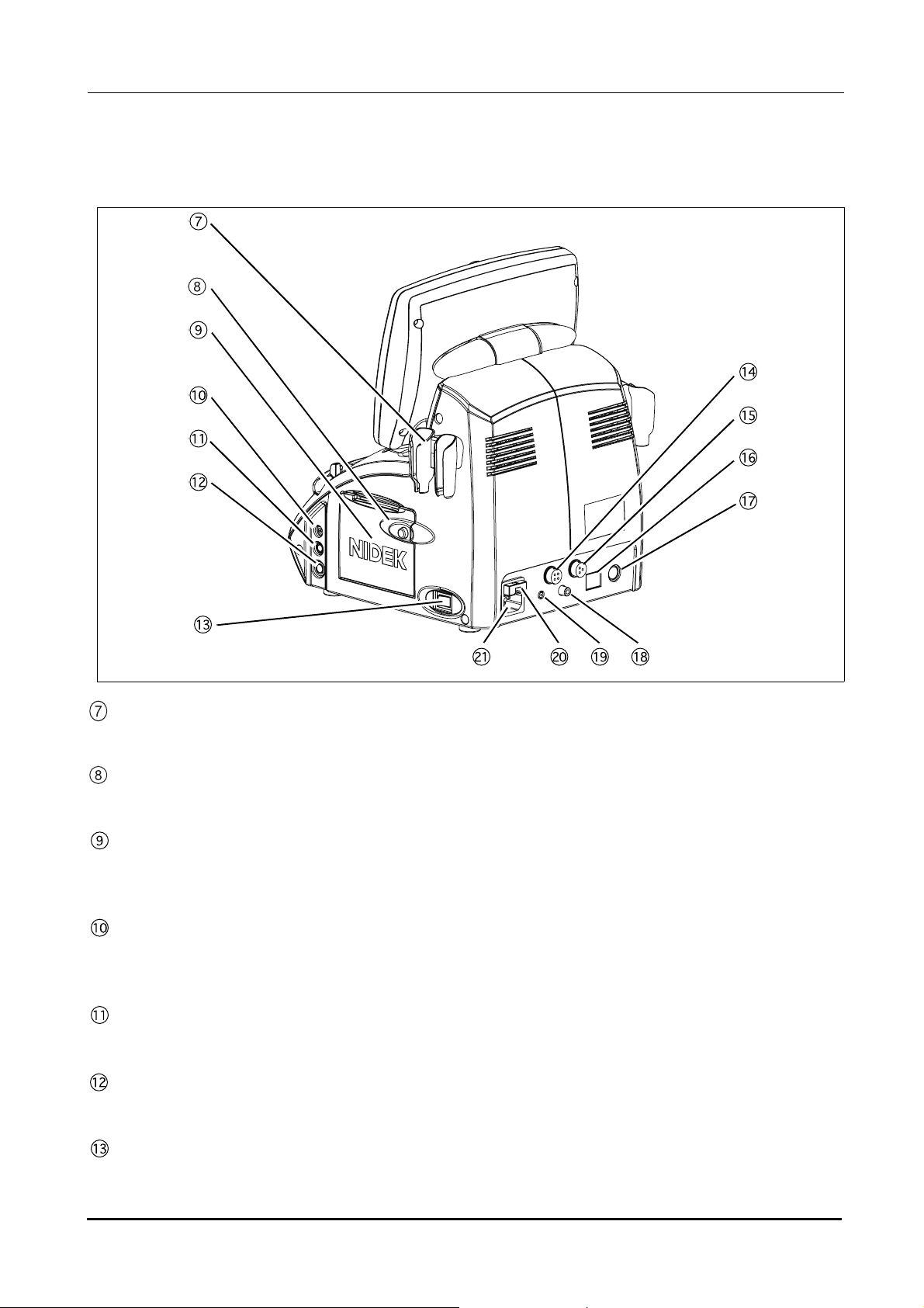
BEFORE USE: Device Description
{ Rear view
Probe holder
Place for keeping the probe.
Cover open button
Pressed to open the printer cover.
Printer cover
Used cover the internal printer with an automatic paper cutter. The printer cover is opened by pressing the
Cover open button when replacing the printer paper.
Probe connector (P)
Used to connect a Pachymetry probe (45° angled probe, 45° angled probe with detachable tip, or straight
probe).
Probe connector (BIO)
Used to connect the A-scan probe.
Probe connector (B)
Used to connect the B-scan probe.
Power switch
Pressed to turn ON and OFF power to the device.
4
Page 19

BEFORE USE: Device Description
External fixation lamp connector
When using the probe stand, power for its fixation lamp is supplied from this connector.
Foot switch connector
The cable plug of the foot switch is connected here.
LAN port
Used to connect the US-4000 with an external device (PC) using a LAN cable for data transmission.
External communication connector
An RS-232C interface connector used to connect the US-4000 with an external device such as a PC for data
transmission. When the US-4000 is connected to a NIDEK Keratometer, data obtained by the Keratometer
can be imported to the US-4000.
Video output terminal
Used to connect the video printer (optional) to print images.
1
Remote connector
Used to connect the remote cable for the video printer (optional).
Fuse holder
Contains fuses. The fuses are blown when overcurrent flows to the device.
Inlet
Used to connect the power cord.
5
Page 20
BEFORE USE: Device Description
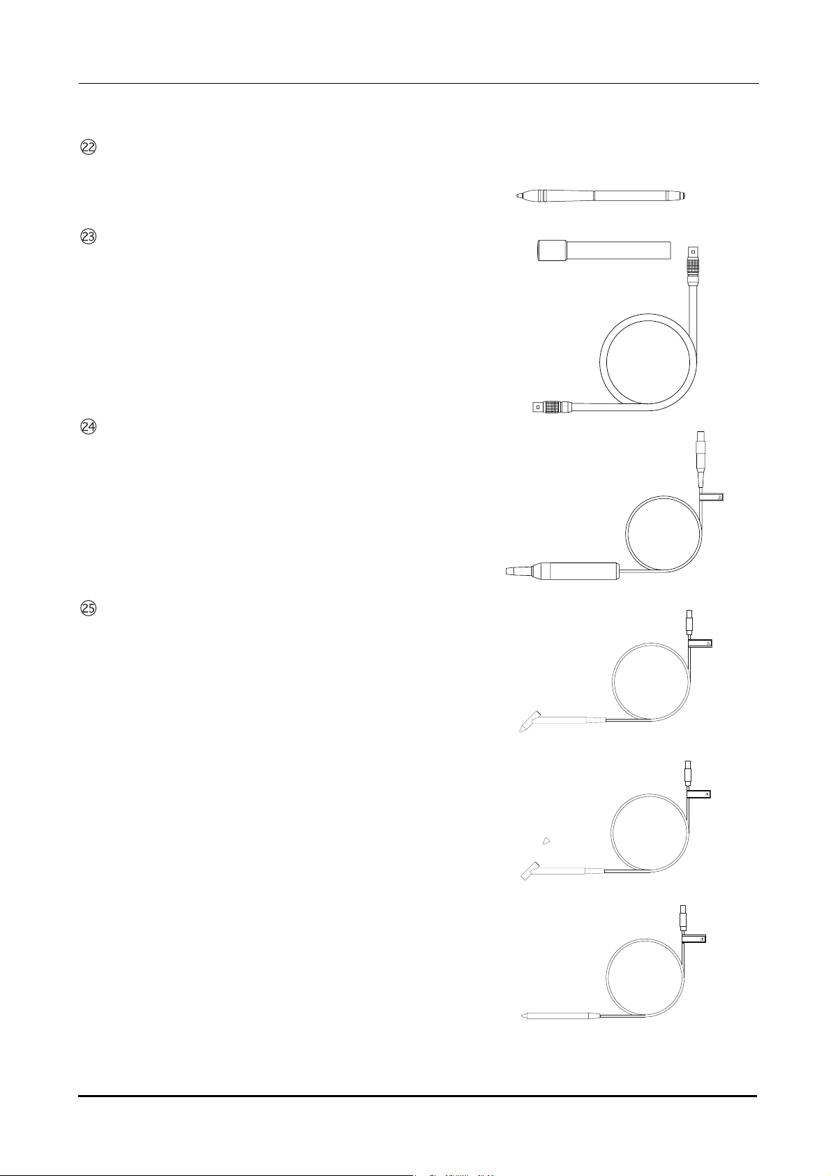
Stylus
Used to manipulate the screen.
B-scan probe
A-scan probe
A solid probe with a built-in fixation lamp
Pachymetry probe
45
° Probe
A solid probe for pachymetry
45° probe (with detachable tip)
A solid probe for pachymetry with a detachable tip
Straight probe
A straight-type solid probe for pachymetry
FRAGILE
(4#)+.'
(4#)+.'
(4#)+.'
6
Page 21
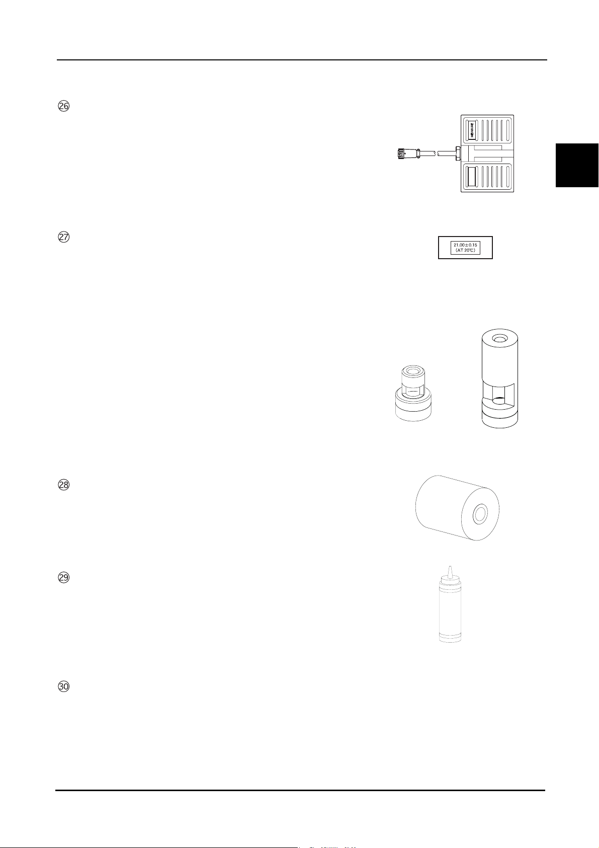
Foot switch
24+06
Used for A-scan biometry, pachymetry, and B-scan imaging.
BEFORE USE: Device Description
Test piece
(for A-scan biometry)
(for pachymetry)
For 45° probe
24+06
For straight probe
1
Printer paper (3 rolls)
Ultrasound gel
Applied to the eyelid for B-scan imaging.
Dust cover
7
Page 22
BEFORE USE: Screen Description
1.5 Screen Description
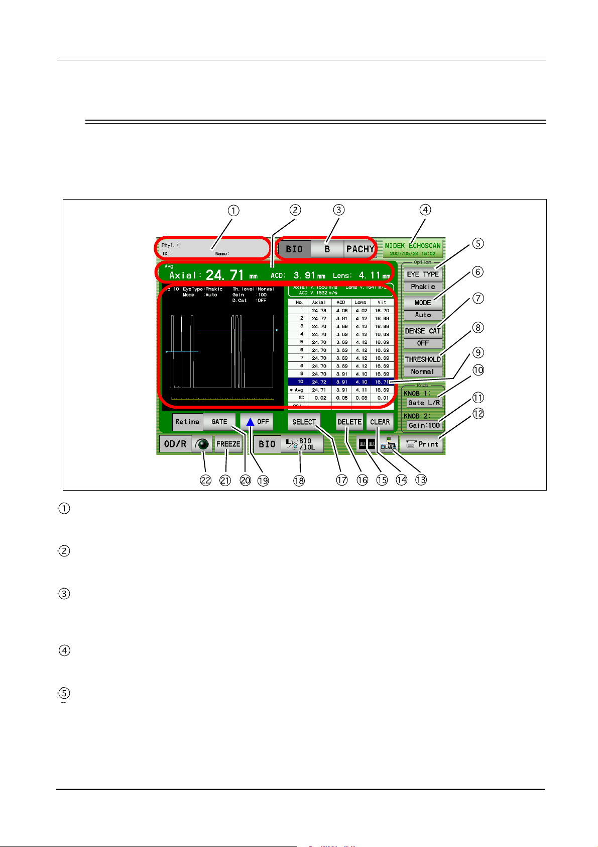
1.5.1 A-scan biometry screen
Patient switch
Pressed to register patient information and display the physician's name and the patient ID.
Measurement value
Displays axial length, anterior chamber depth, and lens thickness.
Mode switch
Pressed to display the desired screen among the A-scan biometry, B-scan imaging, and Pachymetry
screens.
Date and time switch
Displays the current date and time. Pressed to display the A-scan biometry utility screen.
EYE TYPE switch
Pressed to select the type of the eye to be measured.
•Phakic: Phakic Eye
The axial length is converted from the average sonic velocity. Then the anterior chamber depth and the lens
thickness are converted from their respective sonic velocities.
8
Page 23
BEFORE USE: Screen Description
•Phakic2: Phakic Eye
The axial length is calculated by adding the anterior chamber depth, lens thickness, and vitreous body length that
are converted from their respective sonic velocities.
•APhakic: APhakic Eye
•IOL: Pseudophakic Eye
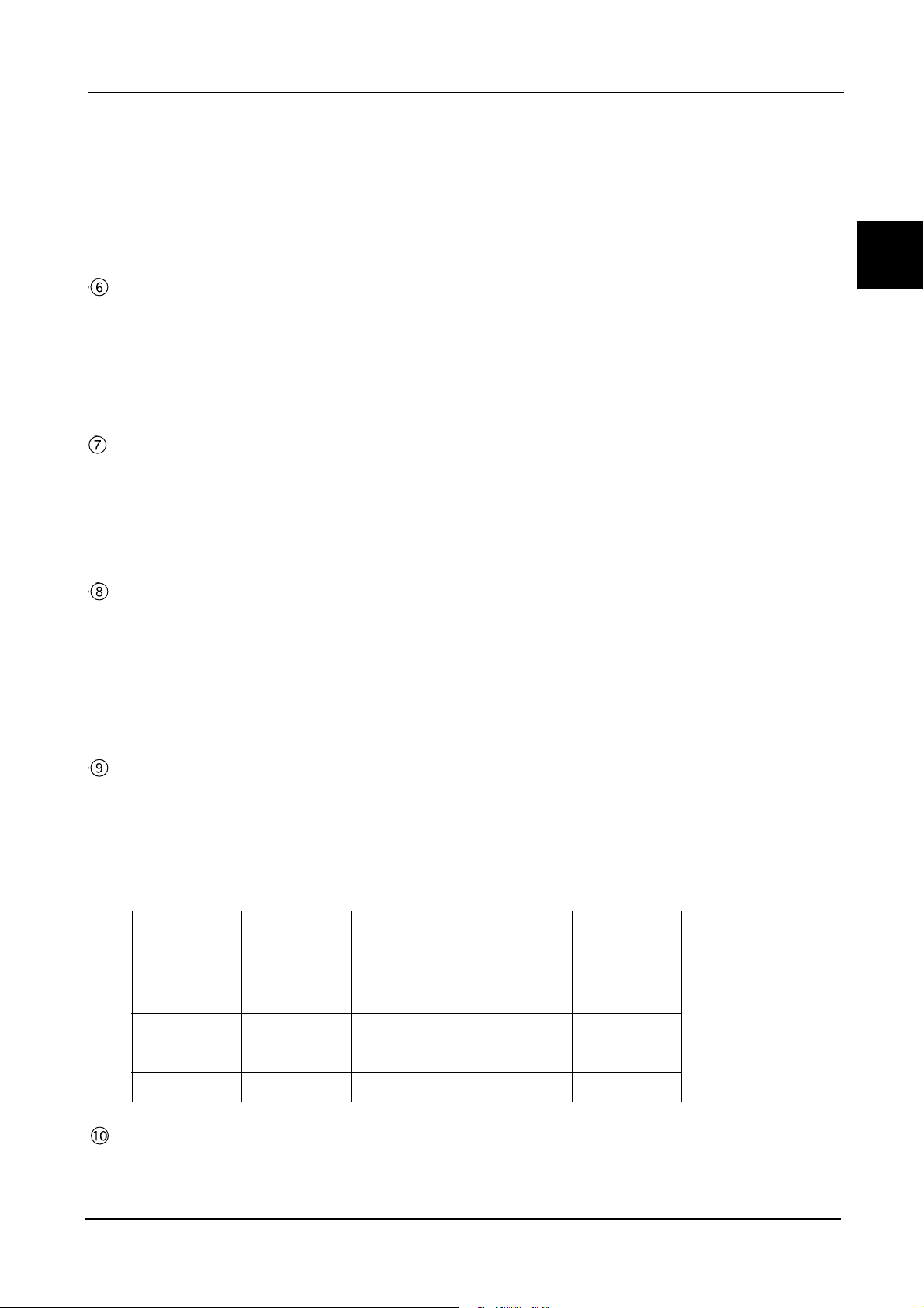
MODE switch
Pressed to change the measurement method.
Auto: The measurement is completed when acceptable measurement conditions continue for a determined
duration.
Speedy: The measurement is completed automatically and the acceptability of the waveform is determined by the
device.
Manual: The measurement is performed by depressing the foot switch.
DENSE CAT switch
OFF: A normal eyes are measured.
ON: An eye with a dense cataract are measured.
(The parameters are changed as follows: THRESHOLD to "Flat Low," gain to 100%, Axial Velocity to 1548 m/s and
Lens Velocity to 1629 m/s. These parameters can be changed in the Utility screen.)
* This switch is not displayed when the Eye Type is Aphakic or IOL.
1
THRESHOLD switch
Pressed to change the programmed threshold which automatically determines the measurement value of
each intraocular part. Each time this switch is pressed, the threshold indication below the switch changes
among “Normal,” “Low,” and “Flat Low.”
* Generally set to “Normal”. If the measurement cannot be performed with an eye with mature cataract even
by increasing the gain, the measuerment may become possible by changing the threshold to “Low” or “Flat
Low.”
Measurement data list indication area
Up to 10 measurement values (three times of three measurement values (nine times in total) in Speedy
mode) for axial length and each intraocular part are indicated. Whenever the measurement data is obtained,
the average (Avg) and standard deviation (SD) in the list are calculated and indicated.
* The measurement value of each intraocular part varies according to the selected Eye Type as shown in the
table below.
Anterior
Eye type
Axial length
chamber
depth
Phakic O O O O
Phakic2OOOO
Lens
thickness
Vitreous body
length
APhakic O - - -
IOL O O - O
Gate display
The specified gate can be moved using Knob 1.
9
Page 24

BEFORE USE: Screen Description
Gain display
Displays the gain during the A-scan biometry.
The gain is adjusted with Knob 2.
PRINT switch
Pressed to print the data being displayed.
Data save switch
Pressed to save data.
CLEAR switch
Pressed to delete the measurement data in the measurement data list. Once the data is deleted, it cannot be
restored.
DUAL switch
Pressed to display the DUAL window where data (waveform and measurement data) is read from the
internal memory, USB flash drive, or the PC.
DELETE switch
Pressed to delete the measurement data in the list.
To delete data, highlight the data to delete by pressing it with the finger or stylus, then press the DELETE switch.
When the DELETE switch is pressed, it changes to the RECALL switch which restores the deleted data.
SELECT switch
Pressed to decide the measurement data to be used for IOL power calculation.
When this switch is pressed, the "*" mark is attached to the selected data which is to be used for IOL power
calculation.
If this function is not used, the average data is used for IOL power calculation.
* The A-scan biometry data to be used for IOL power calculation can also be input in the IOL power calculation
screen.
BIO/IOL Select switch
Pressed to switch the A-scan biometry screen and IOL power calculation screen.
Gate display switch
Pressed to toggle display of each gate between ON and OFF.
Gate switch
Pressed to select the desired gate and enable or disable the manual gate function for each gate. Four gate
types are available: Cornea, Lens-F (anterior), Lens-B (posterior), and Retina.
FREEZE/LIVE switch
Pressed to start or stop the A-scan biometry.
OD/OS switch
Pressed to change the eye to be measured.
10
Page 25
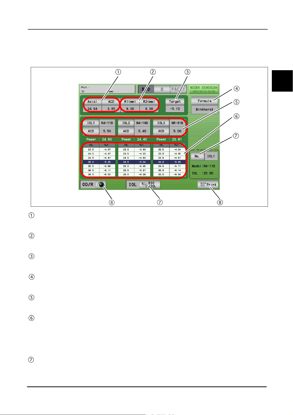
1.5.2 IOL power calculation screen
BEFORE USE: Screen Description
1
A-scan biometry data
A-scan biometry data is automatically input. The data also can be input manually.
Keratometer reading
Corneal curvature radius (mm) and/or corneal refractive power (D) are input.
Tar g et
Target postoperative refractive power is input.
Formula switch
Pressed to select the desired IOL formula.
IOL Select switch
Pressed to select IOLs to be used.
IOL power calculation result table
Displays the IOL power calculation results when the values required for the calculation are input. For each
IOLs, IOL powers that are closest to the calculation result and the expected postoperative refractive power
with those IOL powers are displayed. The highlighted row shows the values closest to the target
postoperative refractive power.
IOL Select switch
Pressed to select the IOL to be used for surgery from IOL1 to IOL3.
The selected IOL is highlighted (white characters on a dark background) on the calculation result printout.
11
Page 26

BEFORE USE: Screen Description
Print switch
Pressed to print the calculation results.
BIO/IOL Select switch
Pressed to switch the A-scan biometry and IOL power calculation screens.
OD/OS switch
Pressed to switch the eye to be measured.
12
Page 27
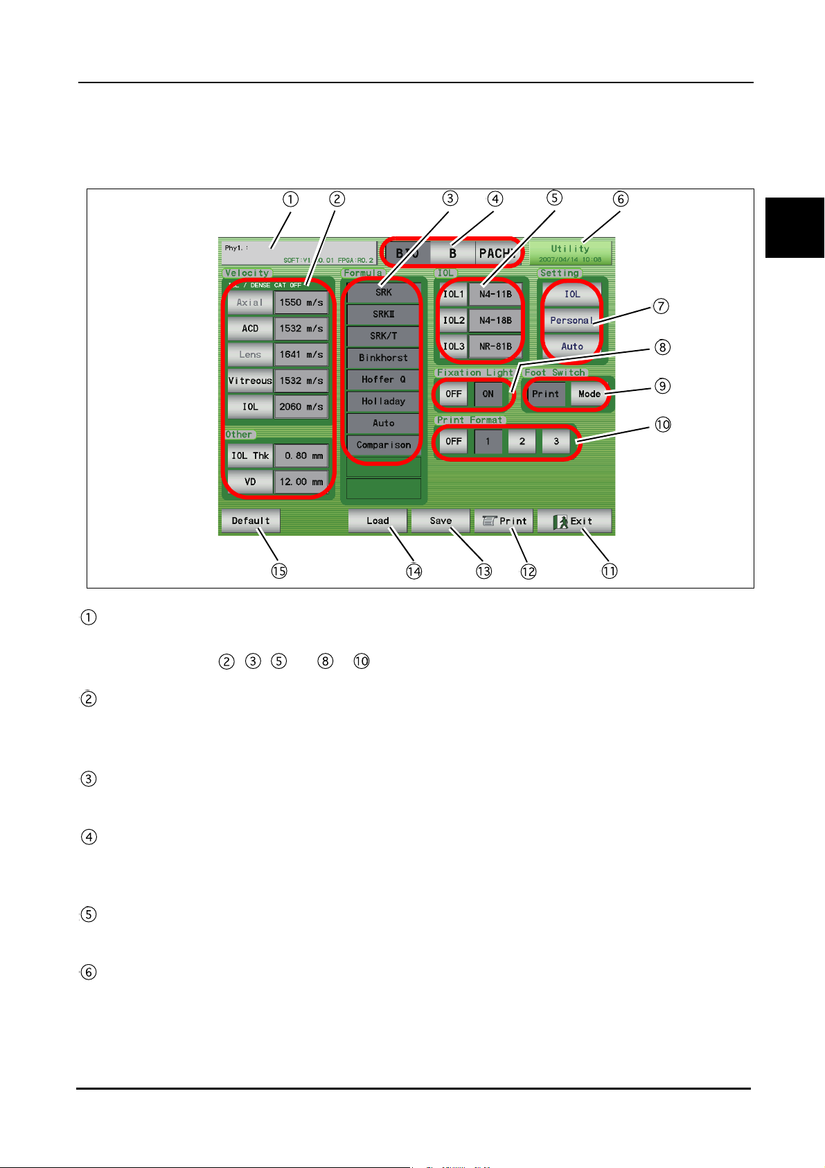
1.5.3 A-scan biometry utility screen
BEFORE USE: Screen Description
1
Physician switch
Pressed to select the physician (1 to 5) and register the Physician data.
Conditions set in , , and to can be set for each physician.
Velocity input area
Pressing each switch displays the ten-key window and the sonic velocity to calculate distance can be input.
Pressing the Default switch resets all the values to the default values.
Formula area
The IOL formula to be used in the IOL power calculation is selected. (Multiple formulas can be selected.)
Mode switches
Pressed to display the desired screen among the A-scan biometry, B-scan imaging, and Pachymetry utility
screens.
IOL area
The IOLs used for IOL1, 2, and 3 are selected.
Utility switch
Pressed to display the Utility screen.
13
Page 28

BEFORE USE: Screen Description
Setting switches
IOL switch: Pressed to register IOLs.
Personal switch: Pressed to calculate the Personal value.
Auto switch: Pressed to perform calculation for the selected IOL within the specified axial length.
Fixation Light switches
Pressed to toggle the fixation light in the A-scan probe between ON and OFF.
Foot Switch switches
Pressed to toggle the function of the PRINT switch between printing and changing of the measurement
mode.
Print Format switches
Pressed to select the desired print format.
Exit switch
Pressed to return to the A-scan biometry screen.
PRINT switch
Pressed to print the A-scan biometry utility settings.
Save switch
Pressed to save the A-scan biometry utility settings.
Load switch
Pressed to return the A-scan biometry utility settings to the saved ones.
Default switch
Pressed to return the A-scan biometry utility settings to the default.
14
Page 29
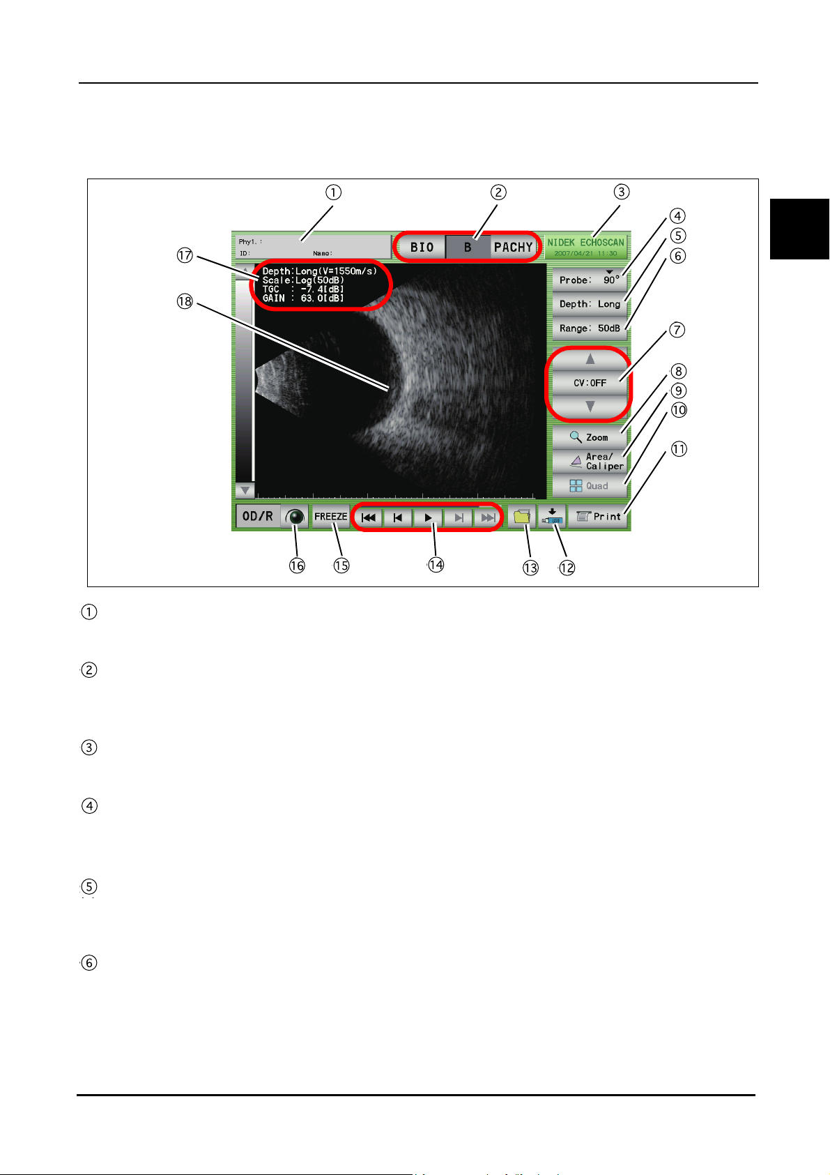
1.5.4 B-scan imaging screen
BEFORE USE: Screen Description
Patient switch
Pressed to register patient information and display the physician's name and the patient ID and name.
1
Mode switches
Pressed to display the desired screen among the A-scan biometry, B-scan imaging, and Pachymetry
screens.
Date and time switch
Displays the current date and time. Pressed to display the B-scan imaging utility screen.
Probe angle switch
Displays the angle of the probe on the eye to be measured. The default value is "90
the switch increases the angle by 45
Observation depth switch
Pressed to switch the observation depth (from the tip of the probe).
Norm (35 mm) ⇔ Long (50 mm)
Display range switch
Pressed to change the display range.
Enabled when the gain curve pattern is set to "Log." The display range can be selected among 10, 20, 30, 40, and
50 dB.
°.
°" and each pressing of
15
Page 30

BEFORE USE: Screen Description
CV (Cross Vector) mode switches
The triangle switches are pressed to move the cross ventor line. The CV switch in the center is pressed to
toggle the CV mode between ON and OFF.
Zoom switch
Pressed to magnify the image on the screen to "×2.5" or "×5."
In the magificination screen, the image navigator "Zoom Navi" is displayed.
Area/Caliper screen switch
Pressed to display the Area/Caliper screen.
Four-image display switch
Pressed to display the Four-image display screen.
The Four-image display screen cannot be displayed if no data is saved in the internal memory.
Print switch
Pressed to print the data being displayed.
Data save switch
Pressed to save the measurement data to an external (USB flash drive or PC) or the internal memory.
Data read switch
Pressed to display the FILE window and read the data from the stored location.
Moving image operation switches
Pressed to play the moving image of about 20 seconds (200 frames) just before the FREEZE switch is
pressed.
The saved moving image is deleted in the following cases:
When the LIVE condition is resumed
When power to the device is turned off
When a New Patient is added
LIVE/FREEZE switch
Pressed to start (LIVE) or stop (FREEZE) the measurement. The same operation can be performed with the
foot switch.
OD/OS switch
Pressed to switch the eye to be measured.
Measurement condition display
Displays the B-scan imaging conditions.
B-scan image display
Displays the B-scan image and cross-vector line.
16
Page 31

1.5.5 B-scan imaging utility screen
BEFORE USE: Screen Description
1
Physician switch
Pressed to select the desired physician (1 to 5) or register Physician data.
Conditions set in to , and to can be set for each physician.
Mode switches
Pressed to display the desired screen among the A-scan biometry, B-scan imaging, and Pachymetry utility
screens.
Utility switch
Pressed to display the Utility screen.
Scan Depth switches
Pressed to select the scan depth at the time of device power-up. (This setting can be changed in the B-scan
imaging screen.)
Setting switches
Pressed to set the sonic velocity to calculate distance in B-scan imaging, TGC and GAIN at the time of
device power-up, and the times of averaging (1 to 5) of the B-scan images.
Scale Color switches
Pressed to toggle the scale color between multiple colors and gray scale.
Print Mode switches
17
Page 32

BEFORE USE: Screen Description
Pressed to toggle the printer for B-scan images between the built-in printer and an external printer.
Ext. Resolution switches
Pressed to toggle the resolution of an external printer between VGA (640 × 400) and SVGA (800 × 600).
Ext. Size switches
Pressed to toggle the area to be printed between Full (Entire screen) and Image (only waveform).
Exit switch
Pressed to return to the B-scan imaging screen.
PRINT switch
Pressed to print the B-scan imaging utility settings.
Save switch
Pressed to save the B-scan imaging utility settings.
Load switch
Pressed to return the B-scan imaging utility settings to the saved ones.
Default switch
Pressed to return the B-scan imaging utility settings to the default.
Save Format switches
Pressed to select the format of the data to be saved between "Raw (raw data)" and "Jpeg (Joint
Photographic Experts Group)", or both.
Log Scale Range switches
Pressed to select the range level for when the scale type (gain curve) at the time of device power-up is
"Log." (This setting can be changed in the B-scan imaging screen.)
Scale Type switches
Pressed to select the gain curve to be used among “Log,” “Linear,” and “S-curve.”
Probe Angle switches
Pressed to set the probe angle at the time of device power-up. (This setting can be changed in the B-scan
imaging screen.)
18
Page 33

1.5.6 Pachymetry screen
BEFORE USE: Screen Description
1
Patient switch
Pressed to register patient information and display the physician's name and the patient ID and name.
Mode switches
Pressed to display the desired screen among the A-scan biometry, B-scan imaging, and Pachymetry
screens.
Date and time switch
Displays the current date and time. Pressed to display the Pachymetry Utility screen.
Waveform display area
Displays the waveform during pachymetry.
AUTO MODE switch
Pressed to toggle the measurement mode between "Auto" and "Speedy."
BIAS switch
Pressed to change the displays of the pachymetry value.
Non: The measurement value is displayed as it is.
µm: The measurement value is displayed with a bias amount (-999 to 999 µm) added.
%: The measurement value is displayed multiplied by a bias rate (10 to 200%).
19
Page 34

BEFORE USE: Screen Description
DELETE switch
Pressed to delete the selected data in the list.
To delete data, highlight the data to delete by pressing it with the finger or stylus, then press the DELETE
switch.
When the DELETE switch is pressed, it changes to the RECALL switch that restores the deleted data.
VALUE switch
Pressed to input the bias value. The bias values are not displayed when the BIAS switch is "Non."
CLEAR switch
Pressed to delete the measurement data at each measurement point.
ALL CLEAR switch
Pressed to delete all the measurement data of the measurement map.
Point display
The specified measurement point can be moved using Knob 1.
Gain display
Displays the gain during pachymetry measurement.
The Knob 2 is used to adjust the gain.
Print switch
Pressed to print the data being displayed.
Measurement value list
Displays the corneal thickness at the specified measurement point.
Displays the Measurement values and their average (Avg) and standard deviation (SD).
MAP switch
Pressed to change the measurement map.
Pressing this switch changes the Map number from 1 to 6.
* Six types of measurement maps are available.
LIVE/FREEZE switch
Pressed to start (LIVE) or stop (FREEZE) the measurement. The same operation can be performed with the
foot switch.
OD/OS switch
Pressed to switch the eye to be measured.
Measurement point display
Displays the measurement points. The measurement point can be moved by pressing the desired point on
the screen.
Corneal thickness display
Displays the average and standard deviation of the measurement value list.
20
Page 35

1.5.7 Pachymetry utility screen
BEFORE USE: Screen Description
1
Physician switch
Pressed to select the desired physician (1 to 5) or register Physician data.
Conditions set in , , , and and the Map No. selected in can be set for each physician.
Mode switch
Pressed to display the desired screen among the A-scan biometry, B-scan imaging, and Pachymetry utility
screens.
Utility switch
Pressed to display the Utility screen.
Print ON and OFF switches
Pressed to enable or disable printing of the pachymetry results.
Foot switch switches
Pressed to toggle the function of the PRINT switch of the foot switch between “Print (printing)” and “Next
(moving to the next measurement point)."
Exit switch
Pressed to return to the Pachymetry screen.
PRINT switch
Pressed to print the Pachymetry utility settings.
21
Page 36

BEFORE USE: Screen Description
Save switch
Pressed to save the Pachymetry utility settings.
Load switch
Pressed to return the Pachymetry utility settings to the saved ones.
Default switch
Pressed to return the Pachymetry utility settings to the default.
Map switch
Pressed to set the map number for at the time of device power-up. (This setting can be changed in the
Pachymetry screen.)
Velocity switch
Pressed to set the sonic velocity to calculate distance.
Probe switch
Pressed to select the type of the Pachymetry probe.
22
Page 37

1.5.8 Utility screen (1/2)
BEFORE USE: Screen Description
1
Mode switch
Pressed to display the desired screen among the A-scan biometry, B-scan imaging, and Pachymetry utility
screens.
Utility switch
Pressed to display the Utility (2/2) screen.
Date Format switches
Pressed to select the desired date display format.
Auto OFF switches
Pressed to set the maximum time of the LIVE condition.
Sound switches
Pressed to change the sound pitch. The sound can be turned off as well.
Save Mode switches
Pressed to toggle the location to save data between the internal or extermal memories.
Ext. Save switches
Pressed to toggle the external location to save data between "USB (USB flash drive)" and LAN (PC)."
Network switch
Pressed to set the network.
23
Page 38

BEFORE USE: Screen Description
Exit switch
Pressed to return to the measurement screen.
Print switch
Pressed to print the utility setting.
Save switch
Pressed to save the utility setting.
Load switch
Pressed to return the settings to the ones saved in the Utility screen.
Default switch
Pressed to return the utility setting to the default.
Communication switches
Pressed to select communicaiton with the device (PC) that is connected using the external communication
connector.
Start Mode switches
Pressed to set the screen (A-scan biometry, B-scan imaging, and Pachymetry) for at the time of device
power-up.
LCD backlight switches
Pressed to select the brightness of the backlight.
24
Page 39

1.5.9 Utility screen (2/2)
BEFORE USE: Screen Description
1
Mode switch
Pressed to display the desired screen among the A-scan biometry, B-scan imaging, and Pachymetry utility
screens.
Utility switch
Pressed to display the utility (1/2) screen.
Date and time switches
Used to set the data and time by pressing the arrow switches.
Exit switch
Pressed to return to the measurement screen.
Parameter switches
Pressed to restore or backup the specified settings.
Touch Panel switch
Pressed to adjust the displayed screen and the coordinates of the touch screen.
25
Page 40

BEFORE USE: Labels and Indications on the Device
1.6 Labels and Indications on the Device
To call the operator’s attention, the device is provided with labels and indications.
If labels are curling up or characters are faded and become barely legible, contact NIDEK or your
authorized distributor.
Indicates that important descriptions are contained in the operator’s manual and that the
operator must refer to the operator's manual prior to operation.
Indicates that the degree of protection against electric shock is of a Type B Applied Part.
Indicates that when the switch is pressed to this symbol side, power is not supplied to the
device.
Indicates that when the switch is pressed to this symbol side, power is supplied to the device.
Indicates that the device must be supplied only with alternating current.
Indicates the fuse rating.
Indicates that the u pedal is to be connected to this port.
Indicates the connector for the fixation lamp cable of the probe stand.
Indicates the manufacturer.
Indicates the date of manufacture.
Indicates that this product shall be disposed of in a separate collection of electrical and
electronic equipment in EU.
26
Page 41

Rear view
BEFORE USE: Labels and Indications on the Device
8TGIKQPU
8TGIKQPU
Left side view
REMOTE
VIDEO
OUT
INPUT
100-120V㨪
SER.NO.
3NNNN
34-14 Maehama Hiroishi-cho Gamagori Aichi Japan
MADE IN JAPAN
LAN
INPUT
100-120V㨪
SER.NO.
34-14 Maehama Hiroishi-cho Gamagori Aichi Japan
MADE IN JAPAN
3NNNN
70VA50/60Hz
XXXX
1
14610-M103-A
8TGIKQPU
INPUT
230V㨪
SER.NO.
34-14 Maehama Hiroishi-cho Gamagori Aichi Japan
MADE IN JAPAN
70VA50/60Hz
XXXX
14610-M103-A
RS-232C
4NNNN
8TGIKQPU
70VA50/60Hz
XXXX
14610-M104-A
+2:
27
Page 42

BEFORE USE: Checking Contents
1.7 Checking Contents
Unpack the contents from the shipping carton and check if all the necessities are included.
The following is included into the standard configuration:
• Main body
• B-scan probe
• A-scan probe
• Pachymetry 45
• Foot switch
• Test piece (for A-scan biometry)
• Test piece (for pachymetry)
• Printer paper
•Power cord
•Stylus
• Ultrasonic gel
• Dust cover
• Spare fuses
• Probe rest
• Operator's manaul
° probe
28
Page 43

2.
OPERATING PROCEDURES
2.1 Operation flow
Connecting accessories
"2.2 Device Setup (Page 32)"
"2.2.1 Connecting power cord (Page 32)"
"2.2.2 Connecting foot switch (Page 33)"
"2.2.3 Attaching probe rest (Page 33)"
“
{ A-scan probe (Page 34)”
“
{ Connecting B-scan probe (Page 35)”
“
{ Connecting Pachymetry probe (Page 35)”
"2.2.5 Connecting Probe stand (optional) (Page 36)"
Preparing for measurement
"2.3 Preparation (Page 37)"
"2.3.1 Adding new patient data (Page 39)"
"2.3.2 Setting physician data (Page 41)"
Starting measurement
A-scan biometry
"2.4 A-scan Biometry (Page 44)"
"2.4.1 Basic operation of A-scan biometry (Page 44)"
"2.4.2 Cautions in A-scan biometry (Page 50)"
"2.4.3 Manual gate (Page 51)"
"2.4.4 Calculation of IOL refractive power (Page 53)"
"2.4.5 Comparison in DUAL screen (Page 56)"
"2.4.6 Setting A-scan biometry utility (Page 58)"
“
{ Changing sonic velocity to calculate distance (Page 58)”
“
{ Setting IOL formula (Page 60)”
“
{ Setting normally used IOL (Page 61)”
“
{ Setting fixation light ON/OFF (Page 62)”
“
{ Setting print format (Page 63)”
“
{ Setting printer mode (Page 89)”
“
{ Inputting IOL data (Page 64)”
“
{ Calculating personal value (Page 66)”
“
{
2
Setting IOL power calculation formula in specified axial length range
(Page 69)”
29
Page 44

OPERATING PROCEDURES: Operation flow
B-scan imaging
"2.5 B-scan Imaging (Page 71)"
"2.5.1 Basic operation of B-scan imaging (Page 71)"
"2.5.2 Probe angle (Page 73)"
"2.5.3 Changing observation depth (Page 73)"
"2.5.4 Changing display range (Page 74)"
"2.5.5 CV mode (Page 76)"
"2.5.6 Zoom (Page 77)"
"2.5.7 Four image display (Page 79)"
"2.5.8 Measuring area on B-scan imaging screen (Area screen) (Page 81)"
"2.5.9 Measuring distance on B-scan image (Caliper screen) (Page 83)"
"2.5.10 Moving image operation (Page 85)"
"2.5.11 Setting B-scan imaging utility (Page 86)"
“
“
“
“
“
“
“
Pachymetry
"2.6 Pachymetry (Page 91)"
"2.6.1 Basic operation of pachymetry (Page 91)"
"2.6.2 Setting pachymetry utility (Page 95)"
“
“
“
“
“
End of operation
"2.8 Completion of Operation (Page 109)"
{ Setting probe angle (Page 86)”
{ Setting scan depth (Page 87)”
{ Setting scale color (Page 87)”
{ Changing gain curve pattern (Page 88)”
{ Setting Log scale range (Page 89)”
{ Setting printer mode (Page 89)”
{ Setting data format (Page 90)”
{ Setting Pachymetry probe (Page 95)”
{ Setting PRINT switch of foot switch (Page 96)”
{ Setting printing of pachymetry results (Page 96)”
{ Setting corneal thickness sonic velocity to calculate distance (Page 97)”
{ Setting map selected at device power-up (Page 97)”
30
Page 45

Initial setting
OPERATING PROCEDURES: Operation flow
"2.7 UTILITY (Page 98)"
"2.7.1 Displaying Utility screen (Page 98)"
"2.7.2 Setting Utility (1/2) (Page 100)"
“
{ Setting backlight (Page 100)“
“
{ Setting Start Mode (Page 100)”
“
{ Setting Communication (Page 101)”
“
{ Setting date and time indication format (Page 101)”
“
{ Setting Auto OFF (Page 102)”
“
{ Setting sound volume (Page 102)”
“
{ Setting save mode (Page 103)”
"2.7.3 Setting Utility(2/2) (Page 107)"
“
{ Adjusting touch screen (Page 107)”
“
{ Setting date and time (Page 107)”
2
31
Page 46

OPERATING PROCEDURES: Device Setup
2.2 Device Setup
2.2.1 Connecting power cord
1 Turn off the power switch.
2 Securely connect the power cord to the inlet on the rear side of the device while adjust-
ing the direction of the plug to the inlet.
3 Position the power cord so that it does not interfere with operation.
4 Securely connect the plug of the power cord to a wall outlet with a protective ground.
* Be sure to connect the power cord to the power outlet with a protective ground.
32
Plug
Page 47

2.2.2 Connecting foot switch
1 Set the foot switch in a convenient position, and position the cable so that it does not
interfere with operation.
2 Align the notch of the foot switch cable plug, and connect it to the connector on the rear
side of the device.
OPERATING PROCEDURES: Device Setup
3 Rotate the knurled ring of the plug clockwise to secure.
2.2.3 Attaching probe rest
1 Attach the probe rest to the main body of the device.
Attach the probe rest so that it fits the shape of the main body.
2
Plug
33
Page 48

OPERATING PROCEDURES: Device Setup
2.2.4 Connecting probe
{ A-scan probe
1 Align the red mark of the cable plug of the probe with that of the probe connector (BIO)
on the front side of the device, and insert the plug as far as it goes.
2 Place the probe on the probe rest of the device.
Plug
Probe
Probe
Probe
34
Page 49

{ Connecting B-scan probe
1 Connect the probe and the plug of the probe cable.
OPERATING PROCEDURES: Device Setup
Probe
Plug
2 Align the red mark of the cable plug of the probe with that of the probe connector (B) on
the front side of the device, and insert the plug as far as it goes.
3 Place the probe on the probe rest of the device.
Probe
Probe
Plug
Probe
2
{ Connecting Pachymetry probe
1 Align the red mark of the cable plug of the probe with that of the probe connector (P) on
the front side of the device, and insert the plug as far as it goes.
2 Place the probe on the probe rest of the device.
Plug
Probe
Probe
Probe
35
Page 50

OPERATING PROCEDURES: Device Setup
2.2.5 Connecting Probe stand (optional)
{ Attaching A-scan probe
1 Hold the probe holder of the probe stand with one hand so that it does not move.
2 Insert the probe held by the other hand from the physician’s side of the probe holder. At
this time, pay attention not to contact the probe tip with the probe holder
.
Hook
3 Fasten the probe cable on the hook with the probe holder moved to the patient’s side. At
this time, loop the probe cable twice on the hook while leaving enough slack.
4 Connect the probe to the device referring to "{ Attaching A-scan probe (Page 36)."
{ Attaching cable for fixation lamp
1 Position the illumination cable so that it does not interfere with the operation.
2 Align the notch of the other side of the plug to the connector for the external fixation lamp
connector on the rear side of the device.
3 Insert the plug directly, and turn the knurled ring of the plug clockwise to secure.
36
Page 51

2.3 Preparation
1 Turn ON ( | ) the power switch on the right side of the device.
The pilot lamp on the front side of the device lights up with a beep sound, and the opening
screen appears.
After a few seconds, the screen becomes the A-scan biometry screen automatically.
If it is hard to see the indications on the screen, rotate the legs to adjust the inclination of the
device.
OPERATING PROCEDURES: Preparation
2
CAUTION
• Remove the USB flash drive when turning ON power to the US-4000.
2 Check the system.
Check the device referring to "4.1 Checks Before Use (Page 117)".
After checks, record each result in the list "4.3 Check List (Page 121)".
Data may become corrupted.
3 Disinfect the probe.
Disinfect the probe with the power switch of the device OFF.
Before measurement, be sure to disinfect the probe for every patient.
When using the probe stand, disinfect the forehead rest and chinrest with gauze dampened
with ethanol.
1) If the tip of the probe is contaminated, clean it as necessary.
37
Page 52

OPERATING PROCEDURES: Preparation
2) Soak the probe tip (max. 20mm) in the following or for 10 minutes.
0.1% Chlorhexdine Gluconate Solution
Ethanol for disinfection
3) Wipe the probe tip, which was soaked in the disinfection solution, with the disinfected
absorbent gauze dampened with ethanol.
Within 20 mm
4) Dry the probe.
4 Prepare the patient.
For A-scan biometry or pachymetry
1) Apply the surface anesthesia to the patient’s eye to be measured.
2) Ask the patient to take a posture suitable for the measurement.
3) Apply the corneal protection agent to the probe tip if necessary.
Be sure not to apply too much corneal protection agent to avoid interference with measurement.
For B-scan imaging
1) Apply the ultrasound gel to the patient’s eyelid.
38
Page 53

2.3.1 Adding new patient data
New patients can be added in the A-scan biometry, B-scan imaging, IOL power calculation, and
Pachymetry screens.
1 Pressing the Patient switch displays the screen shown in Step 2.
OPERATING PROCEDURES: Preparation
2
2 To add a new patient to the Patient list, press the New Patient switch.
Pressing this switch deletes the saved patient information and measurement results and
blanks the fields beside the switches.
3 Press the ID switch to input or change the patient's ID. Then press the Enter switch.
Pressing the ID switch enables input of characters using the keyboard window.
39
Page 54

OPERATING PROCEDURES: Preparation
* A maximum of 14 characters can be input.
4 Press the Name switch to input or change the patient's name. Then press the Enter
switch.
Pressing the Name switch enables input of characters using the keyboard window.
* A maximum of 14 characters can be input.
5 Press the Sex switch select the sex of the patient.
Pressing the Sex switch displays "MALE" and "FEMALE" alternately in the field beside the
switch.
6 Press the Age switch to input or change the patient's age. Then press the Enter switch.
Pressing the Age switch enables input of characters using the ten-key window.
* Numerical characters can be input in the range from 0 to 200.
7 Press the Memo switch to input or change the comments on the patient. Then press the
Enter switch.
Pressing the Memo switch enables input of characters using the keyboard window.
* A maximum of 34 characters can be input.
8 Press the Exit switch to return to the measurement screen.
40
Page 55

2.3.2 Setting physician data
A maximum of five physicians can be saved with individual settings.
1 Press the switch that displays the date and time in the A-scan biometry, IOL power cal-
culation, B-scan imaging, or Pachymetry screen.
OPERATING PROCEDURES: Preparation
2
2 Press the Physician switch to display the setting of the physician to check or change.
Each time the Physician switch is pressed, the next physician number and the settings are
displayed.
3 Holding down the Physician switch displays the keyboard window. If necessary, input or
change the physician's name and press the Enter switch.
41
Page 56

OPERATING PROCEDURES: Preparation
* A maximum of 14 characters can be input.
4 If necessary, change the sonic velocity to calculate distance.
Pressing the switches listed below displays the ten-key window that can be used to input
and change the sonic velocity to calculate distance required for the calculation in the A-scan
biometry, pachymetry, and IOL power calculation.
Pressing the Default switch returns all the settings to the default.
The switches and their default input value and input range are as shown in the table below.
Switch Input value Default value Input range
Axial (Aphakic)
ACD
Lens
(DENSE CAT ON)
Vitreous
IOL
Cornea
IOL Thk
VD
Axial length average sonic
velocity to calculate distance
Anterior chamber sonic
velocity to calculate distance
Lens sonic velocity to
calculate distance
Vitreous body conversion
sonic velocity
IOL sonic velocity to calculate
distance (acrylic)
Cornea sonic velocity to
calculate distance
IOL thickness 0.80 mm 0.02 to 5.00 mm
Vertex distance 12.00 mm 0.00 to 20.00 mm
1550 m/s
(1532 m/s)
1532 m/s 1000 to 2000 m/s
1641 m/s
(1629 m/s)
1532 m/s 500 to 2000 m/s
2060 m/s 500 to 3000 m/s
1640 m/s 1000 to 2000 m/s
1000 to 2000 m/s
1000 to 2000 m/s
* If the Eye Type is "Aphakic" (aphakic eye), the measurement is performed with the sonic
velocity to calculate distancesonic velocity to calculate distance as specified with the
switches above.
* If the DENSE CAT is "ON", the measurement is performed with the sonic velocity to calcu-
late distance as specified with the switches above.
42
5 If necessary, change the IOL formula used for IOL power calculation.
Select the desired IOL formula under "Formula."
Page 57

OPERATING PROCEDURES: Preparation
6 If necessary, input or change the IOL data used for IOL power calculation.
Pressing the IOL switch displays the screen for presetting the IOL data to be used for IOL
power calculation.
When the IOL settings are present in this screen, the IOL power can be calculated soon
after A-scan biometry.
* For details, see
"{ Inputting IOL data (Page 64).”
7 If necessary, calculate the Personal value.
Pressing the Personal switch displays the Personal value calculation screen where the physician inputs various data for the preoperative and postoperative measurement to be calculated.
8 If necessary, change the print format.
Change the print format by pressing any of the switches next to “Print Format”: OFF, 1, 2, or
3.
For details of the print format, see
"{ Setting print format (Page 63).”
9 Press the Save switch to save the settings.
To reset to the previous data, press the Load switch.
* If the Save switch is not pressed, the settings in this screen are not saved in the device.
10 If necessary, press the Print switch to print the various data in the screen.
2
11 To confirm or change the data setting for other physicians, return to Step 2.
12 Press the Exit switch to return to the measurement screen.
43
Page 58

OPERATING PROCEDURES: A-scan Biometry
2.4 A-scan Biometry
2.4.1 Basic operation of A-scan biometry
1 Press the BIO switch to display the A-scan biometry screen.
2 Press the OD/OS switch to select the right or left eye to be measured.
Each time the switch is pressed, the eye to be measured indicated above the switch is toggled between “OD/R” (right eye) and “OS/L” (left eye).
3 Press the EYE TYPE switch to specify the patient’s eye type.
Each time the switch is pressed, the patient’s eye type indicated above the switch is
changed in the order of “Phakic”, “Phakic2”, “Aphakic”, “IOL” and “Phakic”.
* When the patient’s eye type is changed, contents of the sonic velocity to calculate distance
indicated on the left side of the switch are also changed. The patient’s eye type and sonic
velocity to calculate distance are as follows:
44
Phakic: sonic velocity to calculate distance of average (Axial V.), anterior chamber depth
(ACD V.) and lens thickness (Lens V.)
Page 59

OPERATING PROCEDURES: A-scan Biometry
Phakic2: sonic velocity to calculate distance of anterior chamber depth (ACD V.), lens thick-
ness (Lens V.) and vitreous length (Vit V.)
Aphakic: sonic velocity to calculate distance of aphakic eye (Axial V.)
IOL: sonic velocity to calculate distance of anterior chamber depth (ACD V.), IOL (IOL V.)
and vitreous length (Vit V.) and IOL thickness (IOL Thk.)
2
4 Press the MODE switch to specify the measurement mode.
Each time the switch is pressed, the measurement mode indicated above the switch is
changed among “Auto,” “Speedy,” and “Manual.”
Auto: The measurement conditions are evaluated when the measurement is started.
When the measurement conditions are acceptable, a beep sounds and data sampling is performed. The stability of the measurement data is continuously evaluated during the data sampling.
When ten sets of data with the stability of ±0.1 mm are obtained, a beeping sounds and the measurement is automatically stopped.
Speedy: Data sampling begins when the measurement is started. The measurement
automatically stops when three sets of data is obtained.
The measurement data of the past three times are listed. If the measurement is performed more
than three times, the oldest three sets of data is deleted.
Manual: The physician performs data sampling when the measurement is started.
The measurement automatically stops when 10 sets of data are obtained.
45
Page 60

OPERATING PROCEDURES: A-scan Biometry
5 Press the FREEZE switch or the MEASURE switch of the foot switch to start A-scan
biometry.
The indication of the switch becomes “LIVE”, and A-scan biometry starts.
6 Put the A-scan probe on the center of the cornea.
1) A-scan waveform appears, and A-scan biometry is performed according to the selected
measurement mode.
2) Adjust the gain by rotating Knob 2 so that a proper A-scan waveform can be obtained.
The gain can be changed in the range between 0 and 100 in 10 dB increments.
* The most recently selected gain is indicated in this screen after the device power is
turned ON again.
46
Page 61

OPERATING PROCEDURES: A-scan Biometry
3) To measure eyes with hypermature cataract, press the DENSE CAT switch.
4) If necessary, press the THRESHOLD switch to change the programmed threshold
among “Normal,” “Low,” and “Flat Low” with which the program determines the acceptability of the measurement value of each intraocular part.
2
* If there is an additional echo near the threshold preceding any of the valid echoes, redo the mea-
surement referring to "2.4.3 Manual gate (Page 51)".
• When the patient’s eye type is Aphakic, the anterior chamber depth (ACD), lens thickness
(Lens) and vitreous length (Vitreous) are not measured. For IOL implanted eyes, the lens
thickness (Lens) is not measured and the value between the cornea and the front surface of
the IOL is indicated as the anterior chamber depth (ACD).
• The Auto mode is an auxiliary function to facilitate the A-scan biometry operation. It is not
intended for clinical judgement. When using the values obtained in Auto mode for IOL
power calculation, physicians have to examine the obtained values.
7 Repeat Step 5.
Repeat Step 5 several times to ensure validity of the obtained data.
Up to 10 sets of data of the axial length and each intraocular part can be indicated on the list.
8 Arrange the data if necessary.
To delete data due to fluctuations comparied to other data, arrange the data according to the
procedure below.
47
Page 62

OPERATING PROCEDURES: A-scan Biometry
To delete one set of data, highlight the data with the stylus or finger and press the DELETE
switch.
To undo deletion of a set of data, highlight the No. of the deleted data with the stylus or finger and press the RECALL switch.
To delete all the measured data on the list, press the CLEAR switch. (However, this deletion
cannot be undone. Care should be taken when data is deleted in this manner.)
* Each time the data is deleted and the deletion is undone, the average (Avg) and standard
deviation (SD) are recalculated.
48
Page 63

OPERATING PROCEDURES: A-scan Biometry
9 If necessary, select the measured data used for IOL power calculation.
To use the measurement data in the data list, highlight the data with the stylus or finger, and
press the SELECT switch to enter. (The “*” mark is indicated next to the No. of the selected
data.)
* If this setting is not performed, the average value is used for IOL power calculation.
2
10 Press the Data save switch to save the data obtained in the A-scan biometry screen.
In this window, a maximum of 12 sets of measurement data displayed in the A-scan biometry screen can be saved (to the internal memory) with the date and patient's name. A maximum of 1000 sets of measurement data can be saved in an external memory.
49
Page 64

OPERATING PROCEDURES: A-scan Biometry
2.4.2 Cautions in A-scan biometry
To carry out A-scan biometry smoothly and accurately, pay attention to the following:
(1) Instruct the patient not to move their eyes.
If the patient is nervous, instruct them to relax.
(2) Confirm that the probe is in contact with the center of the cornea.
Contact between the probe and the cornea is an important factor in obtaining accurate Ascan biometry values. Change the probe contact angle so that a proper A-scan waveform is
obtained.
A proper A-scan waveform means that it has echoes from the following three parts: the cornea, and the anterior and posterior surfaces of the lens. An proper A-scan waveform has
also a large retinal echo which rises sharply accompanying a small scleral echo.
When the echoes of the retina and sclera are not separated, rotate Knob 2 to decrease the
gain.
(3) Check the following points before freezing the obtained A-scan biometry value:
a) Has a proper A-scan waveform been obtained?
b) Is the probe in contact with the cornea properly?
c) Is the patient’s eye fixed?
d) Are the obtained values stable?
* If the A-scan biometry is performed hurriedly, accurate values cannot be obtained. Take enough
time for the A-scan biometry.
(Is the variations in the obtained values within ±0.05 mm?)
(4) In Auto mode, if the display does not stop (FREEZE) even when the obtained values are indicated,
the retinal echo may have not risen properly or there is no lens echo or it is too weak.
Change the contact and angle of the probe so that a proper waveform as shown below is
obtained.
ٕ
ٕ
ٕ
ٕ
50
Proper
Improper
Page 65

2.4.3 Manual gate
If there is an additional echo near the threshold value preceding any of the valid echoes, this addi-
tional echo is mistakenly considered a valid echo. This Manual Gate function is used to eliminate the
influence of extraneous echoes. This function is also used if there are many multiple echoes in the
measurement of an eye with an IOL implanted.
The Manual Gate can be displayed by selecting a gate type (Cornea, Lens-F (anterior), Lens-B (pos-
terior), or Retina) and pressing the ON/OFF switches. Then the displayed gate position can be
adjusted.
OPERATING PROCEDURES: A-scan Biometry
2
1 In the FREEZE screen, confirm that no improper A-scan waveform or intraocular biome-
try values are found.
1) Press the MEASURE switch of the foot switch or the LIVE switch to stop the A-scan
biometry operation.
2) In the FREEZE screen, observe the A-scan waveform and intraocular biometry values.
If the A-scan biometry values are improper due to extraneous echoes, go to Step 2.
2 Adjust the Manual Gate position.
1) Select the gate type by pressing the GATE switch and press the ON/OFF switch to display the Manual Gate.
* There are gates for Cornea, Lens-F (anterior), Lens-B (posterior), and Retina. Move each
gate to the respective echo.
2) Turn Knob 1 and move each gate just to the left side of the respective echoes.
* The gate can also be moved using the stylus or finger.
51
Page 66

OPERATING PROCEDURES: A-scan Biometry
3 Restart the A-scan biometry operation and confirm the change of the values of each
intraocular part by the Manual Gate.
1) Press the MEASURE switch on the foot switch or the FREEZE switch to restart the measurement.
2) Check whether the values of each intraocular part are changed.
Echoes on the left side of the set manual gate are no longer considered valid echoes, and all
intraocular values are changed by the Manual Gate function.
* Since an extraneous echo in the A-scan biometry may indicate an intraocular lesion, it is recom-
mended to check for such a possible lesion using other methods (such as B-scan imaging).
52
Page 67

2.4.4 Calculation of IOL refractive power
Pressing the IOL switch after the A-scan biometry displays the IOL power calculation screen in which
the IOL power is calculated. The calculation is performed when the necessary data is input, and the
calculated results of the selected IOL type are listed. The IOL data must be input in advance referring
to “
{Inputting IOL data (Page 64).”
1
After the A-scan biometry, press the BIO/IOL switch to display the IOL power calculation screen.
OPERATING PROCEDURES: A-scan Biometry
2
2 Press the OD/OS switch to select the eye in which to implant an IOL.
3 Press the R1 and R2 switches to input the corneal curvature radius (mm) and/or corneal
refractive power (D).
Pressing any of the R1 and R2 switches displays the ten-key window. After inputting the values using the ten-key, press the Enter switch.
4 Press the Formula switch to select the IOL formula used to calculate the IOL power.
Each time the switch is pressed, the IOL formula registered in the physician setting screen is
indicated in order.
The selected IOL formula is indicated on the switch.
Auto: An IOL formula is automatically selected based on the axial length.
Comparison: The IOL power is calculated with all the IOL formula.
* The most recently selected IOL formula is indicated in this screen after the device power is
turned OFF and then ON again.
53
Page 68

OPERATING PROCEDURES: A-scan Biometry
5 Press any of the IOL 1, IOL 2, and IOL 3 switches to display the IOL list window. Select
up to three IOL types to be used for the IOL power calculation.*
1) Press the IOL number to be changed to display the IOL list window.
2) Select the IOL in the list with the stylus or finger.
* If there is no desired IOL, register a new one.
2
54
3) Press the OK switch to determine the IOL used for the calculation and close the window.
* To close the IOL list window without any changes, press the Cancel switch.
4) To change the IOL selected with other switches, repeat Steps 1) to 3).
* The same IOL cannot be selected with multiple switches.
6 If necessary, temporarily change the IOL constant selected in Step 5.*
1) Press the Aconst switch (such as ACD and SF) just below the IOL whose IOL constant is
the item to be changed to display the numeric key window.
* The indicated switch is one of “Aconst,” “SF,” and “ACD” according to the IOL formula to
be used.
*2 If three types of IOLs are not necessary for the IOL refractive power calculation, leav-
ing the IOL model name blank deletes the registered IOL data, and the deleted IOLs
are not used for the calculation. (For the inputting method, see “
(Page 64).” Unless this setting is saved in the IOL data input screen, the blank IOL
model name is returned to the original once power to the device is turned off.
3
{ Inputting IOL data
Page 69

OPERATING PROCEDURES: A-scan Biometry
*3 Changes made in this step are temporary, and the values return to the original once
power to the device is turned off.
2) Input a new IOL constant using the ten-key window, and press the Enter switch.
* The following lists the switches and ranges of each constant. Values cannot be input
outside the ranges:
Aconst (A constant) (Aconst switch) ........100 to 130
ACD (Predicted postoperative anterior chamber depth) (ACD switch)..... 1.6 to 9.99
SF (Surgeon factor) (SF switch)... 0 to 9.99
* Each time the BS switch is pressed, the input numerical values are deleted from the
right end.
* To close the ten-key window without any changes, press the Cancel switch.
3) To change the IOL constant of the other two IOLs, repeat Steps 1) to 2).
7 Input the obtained data of each intraocular part to carry out the IOL power calculation.
1) Select either the right (OD/R) or left (OS/L) eye to enter data first.
2) Press the Axial switch to display the ten-key window, and input the axial length.
* When the A-scan biometry is completed, the average or measured data with a “ ”
mark has already been input.
3) Press the R1/R2 switch to display the ten-key window, and input the corneal curvature or
refractive power.
* The following are the ranges of corneal curvature and corneal refractive power, and the
values cannot be input outside the ranges:
Corneal curvature: 5.00 to 19.99 mm
Corneal refractive power: 20.00 to 60.00 D
2
* When the NIDEK Keratometer is connected, the corneal curvature or refractive power
that was obtained with the Keratometer has been already input.
4) Press the Target switch to display the ten-key window, and input the desired postoperative refractive power.
* The range of the desired postoperative refractive power is between -10.00 D and +10.00 D, and
the value cannot be input outside the range.
5) The IOL powers for each set of input data are calculated.
The IOL power which is the closest to the desired postoperative refractive power is highlighted in
the middle row on the calculation list.
6) Input the data for the other eye in the same manner as Steps 2) to 4) to calculate the IOL
power for it.
8 Press the Print switch to print the calculation results.
55
Page 70

OPERATING PROCEDURES: A-scan Biometry
2.4.5 Comparison in DUAL screen
1 Press the DUAL switch in the A-scan biometry screen to display the DUAL screen.
2 Press the Data Read switch below the table on the left side of the screen to display the
file list.
3 Select the desired file from the list to be displayed on the left side (1) of the screen by the
stylus or finger, and press the Display switch.
56
Page 71

OPERATING PROCEDURES: A-scan Biometry
4 Press the Data Read switch below the table on the right side of the screen to display the
file list.
5 Select the desired file from the list to be displayed on the right side (2) of the screen by
the stylus or finger, and press the Display switch.
2
6 Press the LIST/WAVE switch to display the lists.
7 Select appropriate data from the list by the stylus or finger.
8 Press the LIST/WAVE switch to display the waveform and confirm that it is appropriate.
9 Press the IOL switch to calculate the IOL power.
57
Page 72

OPERATING PROCEDURES: A-scan Biometry
2.4.6 Setting A-scan biometry utility
1 Press the switch that indicates the date and time in the A-scan biometry screen to dis-
play the A-scan biometry utility screen.
{ Changing sonic velocity to calculate distance
1 Press any of the Axial, ACD, Lens, Vitreous, and IOL switches to change the sonic
velocity to calculate distance. To change other values, press the IOL Thk or VD switch.
58
Page 73

OPERATING PROCEDURES: A-scan Biometry
2
Input the sonic velocity to calculate distance and other values and press the Enter switch.
2
Switch Input value
Axial
(Aphakic)
ACD
Lens
(DENSE CAT ON)
Vitreous
IOL
IOL Thk
V. D.
Axial length average sonic
velocity to calculate distance
Anterior chamber sonic
velocity to calculate distance
Lens sonic velocity to
calculate distance
Vitreous body sonic velocity to
calculate distance
IOL sonic velocity to calculate
distance (PMMA)
IOL thickness 0.80 mm 0.02 to 5.00 mm
Vertex distance 12.00 mm 0.00 to 20.00 mm
Default
value
1550 m/s
(1532 m/s)
1532 m/s 1000 to 2000 m/s
1641 m/s
(1629 m/s)
1532 m/s 500 to 2000 m/s
2060 m/s 500 to 3000 m/s
Input range
1000 to 2000 m/s
1000 to 2000 m/s
* If the Eye Type is "Aphakic" (aphakic eye), the measurement is performed with the sonic
velocity to calculate distance as specified with the switches above.
* If the DENSE CAT is "ON", the measurement is performed with the sonic velocity to calcu-
late distance as specified with the switches above.
Pressing the Default switch resets all the settings to the default values.
3 Press the Save switch to save the data.
59
Page 74

OPERATING PROCEDURES: A-scan Biometry
{ Setting IOL formula
1 Select the IOL formula(s) to be used for the IOL power calculation.
Auto: An IOL formula is automatically selected based on the axial length.
2 Press the Save switch to save the setting.
60
Page 75

{ Setting normally used IOL
1 Press any of the IOL1, 2, or 3 switches to display the IOL list.
OPERATING PROCEDURES: A-scan Biometry
2
2 Select the desired IOL from the IOL list, and press the OK switch.
3 Press the Save switch to save the setting.
61
Page 76

OPERATING PROCEDURES: A-scan Biometry
{ Setting fixation light ON/OFF
Toggle the fixation light inside the A-scan probe between lit and unlit.
1 Select "ON" or "OFF."
2 Press the Save switch to save the setting.
62
Page 77

{ Setting print format
Set the print format in the A-scan biometry.
1 Select the print format from "Off," "1," "2," and "3."
Patient data - O O O
Physician's name - O O O
Operation conditions - O O O
A-scan biometry
Eye (left or right) - O O O
Measurement data list, the average value
A-scan biometry value used for IOL power
calculation
Value with "*" in the IOL list on the screen
Printed item Off 1 2 3
(Avg) and the standard deviation (SD)
OPERATING PROCEDURES: A-scan Biometry
2
-O--
-OOO
Selected A-scan waveform - O O -
Print date and time - O O O
Printed item Off 1 2 3
Patient data - O O O
Physician's name - O O O
Operation conditions - - - O
IOL formula - O O O
Eye (left or right) - O O O
IOL power calculation
A-scan biometry value used for IOL power
calculation
Value with "*" in the IOL list on the screen
Selected A-scan waveform - - - O
Input axial length - O O O
Corneal curvature radius (mm)/ Refractive
power (D)
Target postoperative refractive power - O O O
IOL data, optimal IOL value, and selectable
IOL and refractive power
(Selectable range of IOL:
± 1.0D or ± 1.5D)
---O
-OOO
-
O
(
± 1.5D)
O
(± 1.0D)O(± 1.0D)
Print date and time - O O O
2 Press the Save switch to save the setting.
* If the Save switch is not pressed, the setting is reset to the original once power to the
device is turned off.
63
Page 78

OPERATING PROCEDURES: A-scan Biometry
{ Inputting IOL data
When the IOL data is preset in this screen, it becomes possible to calculate the IOL power to be used
for the surgery soon after the A-scan biometry. (A maximum of 16 sets of IOL data can be input.)
1 Press the switch with the date and time indications in the A-scan biometry screen.
2 Press the IOL switch.
64
Page 79

OPERATING PROCEDURES: A-scan Biometry
3 Press the box to input (or change) with the stylus or finger.
If any box in the Model and Manuf column is pressed, the keyboard window is displayed. If
any box in the Aconst, SF, and ACD columns is pressed, the ten-key window is displayed.
2
4 Input (or change) the IOL data.
The switches and changeable contents are as follows:
Model: Model of the IOL
Manuf.: Manufacturer
Aconst: A constant
SF: Surgeon factor
ACD: Predicted postoperative anterior chamber depth
* If three types of IOLs are not necessary for the IOL refractive power calculation, leaving the
IOL model name blank deletes the registered IOL data, and the deleted IOLs are not used
for the calculation.
5 Press the Save switch to save the data.
65
Page 80

OPERATING PROCEDURES: A-scan Biometry
{ Calculating personal value
The values such as the IOL constant can be calculated by inputting the corneal curvature radius/
refractive power, axial length, IOL power and postoperative refractive power.
1 Press the switch that indicates the date and time to display the A-scan biometry utility
screen.
2 Press the Personal switch.
3 Input the postoperative refractive power.
Pressing any of the postoperative power switches displays the ten-key window which
enables inputting the refractive power required to calculate the IOL constant.
The following lists the switches (setting items) and ranges of the refractive power. Values
cannot be input outside the ranges:
Sphere switch (postoperative spherical power) - 20.00 to + 20.00 D
66
Page 81

OPERATING PROCEDURES: A-scan Biometry
Cylinder switch (postoperative cylindrical power) - 20.00 to +20.00 D
4 Press the Axial switch to input the axial length of the eye to be treated.
Pressing this switch displays the ten-key window which enables inputting of the axial length.
2
The input range of axial length is between 12.00 and 40.00 mm, and the axial length cannot
be input outside the range.
5 Press the R1/R2 switches to input the corneal curvature radius or corneal refractive
power of the eye to be treated.
Pressing this switch displays the ten-key window which enables inputting of the corneal curvature radius or corneal refractive power.
The input ranges of corneal curvature radius and corneal refractive power are described
below, and the values cannot be input outside the ranges. In addition, the units (mm or D)
are automatically changed according to the input value.
Corneal curvature 5.00 to 19.99 mm
Refractive power 20.00 to 60.00 D
6 Press the Implanted IOL Power switch to input the implanted IOL power.
Pressing this switch displays the ten-key window which enables inputting the implanted IOL
power.
The input range of the implanted IOL power is between -40.00 and +40.00 D, and the value
cannot be input outside the range.
67
Page 82

OPERATING PROCEDURES: A-scan Biometry
When the necessary data is input, the IOL constant is automatically calculated, and Aconst
(A constant), SF (surgeon factor) and ACD (predictable postoperative anterior chamber
depth) are indicated in the boxes under “Personal Value”.
7 If necessary, press the Print switch to print the data on this screen.
8 Press the Exit switch twice to return to the A-scan biometry screen.
68
Page 83

OPERATING PROCEDURES: A-scan Biometry
{ Setting IOL power calculation formula in specified axial length range
1 In the A-scan biometry utility screen, press the Auto switch to display the Auto screen.
2
2 Press the Min Max switch to display the ten-key window. Input the axial length range
(values) using the ten-key. (Unit: mm)
3 Pressing any of the Formula switches displays the Formula select screen. Select the
desired IOL formula for each axial length range.
69
Page 84

OPERATING PROCEDURES: A-scan Biometry
4 Press the Save switch to save the setting.
Press the Load switch to reset the settings to the saved ones. Pressing the Default switch resets the
settings to the default.
5 If necessary, press the Print switch to print the setting.
6 Press the Exit switch twice to return to the A-scan biometry screen.
70
Page 85

2.5 B-scan Imaging
2.5.1 Basic operation of B-scan imaging
1 Press the B switch to display the B-scan imaging screen.
OPERATING PROCEDURES: B-scan Imaging
2
2 Press the OD/OS switch to select the right or left eye for which the B-scan imaging is to
be performed.
Each time the switch is pressed, the eye indication above the switch changes between "OD/
R" (right eye) and "OS/L" (left eye).
71
Page 86

OPERATING PROCEDURES: B-scan Imaging
3 Press the FREEZE switch or the MEASURE switch of the foot switch to start the image
observation.
4 Apply the B-scan probe on the eyelid of the patient.
5 As necessary, change the settings such as TGC (-20 to 0 dB), GAIN (0 to 90 dB), probe
angle, observation depth, display range, and display color. Then start the image observation.
6 When the desired image is captured, press the LIVE switch or press the MEASURE
switch of the foot switch to FREEZE the image.
7 If necessary, press the PRINT or Data Save switch to save the necessary data.
72
Page 87

2.5.2 Probe angle
The angle of the probe touching the eyelid is displayed. Each pressing of the switch rotates the angle
by 45
° clockwise.
(ex.: 0
° → 45° → 90° → 135° → 180° → 225° → 270° → 315° → 0° → 45° → ...)
OPERATING PROCEDURES: B-scan Imaging
2
2.5.3 Changing observation depth
Press the Depth switch to change the observation depth.
73
Page 88

OPERATING PROCEDURES: B-scan Imaging
2.5.4 Changing display range
The Range switch is available when the gain curve is set to "Log." Each pressing of the Range switch
changes the value as "50
The B-scan image is displayed in 256 gray scales within the range of the echo intensity (50 dB).
The range of the echo intensity can be changed as necessary. For example, when the range is
changed to 30 dB, the echo intensity is displayed in 256 gray scales within the range of 30 dB. By
adjusting the range of 30 dB to the desired echo intensity, the image of the selected echo intensity can
be displayed in clear and emphatic contrast.
→ 40 → 30 → 20 → 10 → 50dB..."
・Range: 50 dB
Brightness
F$
Echo intensity
・Range: 30 dB Middle intensity echoes are displayed clearly
Brightness
74
F$
Echo intensity
Page 89

・Range: 30 dB Low intensity echoes are displayed clearly
Brightness
OPERATING PROCEDURES: B-scan Imaging
F$
Echo intensity
・Range: 30 dB High intensity echoes are displayed clearly
Brightness
F$
Echo intensity
2
75
Page 90

OPERATING PROCEDURES: B-scan Imaging
2.5.5 CV mode
1 Press the "CV:OFF" switch.
2 Pressing the triangle switches moves
the cross-vector line. The A-scan waveform for the cross-vector line and the
entire B-scan image are displayed
together. The cross-vector line also can
be moved with the stylus or finger.
Cross-vector line
A-scan waveform
76
Page 91

2.5.6 Zoom
1 Press the Zoom switch in the B-scan imaging screen to display the Zoom screen.
OPERATING PROCEDURES: B-scan Imaging
2
2 Press the Draw Ratio switch to toggle the magnification between x2.5 and x5.
77
Page 92

OPERATING PROCEDURES: B-scan Imaging
3 Rotate Knob 1 and 2 to move the area of magnification in the up, down, left, and right
directions.
A square appears in the Zoom Navi display to indicate the area of magnification. The area of
magnification can be moved by touching the desired part in the Zoom Navi display with the
stylus or finger.
4 Press the Print switch to print the image on the screen.
5 Press the Exit switch to return to the B-scan imaging screen.
78
Page 93

2.5.7 Four image display
1 Press the Quad switch in the B-scan imaging screen to display the four image display
screen.
If the desired data is stored in an external storage device, import the data by pressing the
Data Read switch.
OPERATING PROCEDURES: B-scan Imaging
2
2
Press the image or the MemNo. switch to select an image. Pressing the and
switches displays 12 saved images consecutively (three consecutive sets of four images).
3 Press the Display switch to display only one image.
79
Page 94

OPERATING PROCEDURES: B-scan Imaging
4 Press the Delete switch to delete the selected image.
5 Press the Exit switch to return to the B-scan imaging screen.
80
Page 95

OPERATING PROCEDURES: B-scan Imaging
2.5.8 Measuring area on B-scan imaging screen (Area screen)
1 Press the Area/Caliper switch in the B-scan imaging screen to display the Area/Caliper
screen.
2
2 Press the Area/Caliper switch in the Area/Caliper screen to display the Area screen.
3 Move the "×" mark on the image to the desired start point by turning Knob 1 and 2, or
specify the start point with the stylus and confirm it by pressing the Set switch.
81
Page 96

OPERATING PROCEDURES: B-scan Imaging
4 Repeat Step 3 to specify the desired range.
To change the position of the previous point, press the Back switch.
To clear all the points, press the All Clear switch.
5 Specify the end point to the same position as the start point, and press the Calculation
switch to calculate the area.
6 Press the Print switch to print the image in the screen.
7 Press the Exit switch to return to the B-scan imaging screen.
82
Page 97

OPERATING PROCEDURES: B-scan Imaging
2.5.9 Measuring distance on B-scan image (Caliper screen)
1 Press the Area/Caliper switch in the B-scan imaging screen to display the Area/Caliper
screen.
2
2 Press the Area/Caliper switch in the Area/Caliper screen to display the Caliper screen.
3 Select the desired marker (+, +, x, or x).
83
Page 98

OPERATING PROCEDURES: B-scan Imaging
4 Move the selected marker using Knob 1 and 2 or specify the desired point using the sty-
lus.
5 Select the marker paired with the selected one (+ and + / x and x) and specify its posi-
tion as in Step 4.
The distance is displayed when the marker positions are specified.
6 Press the Print switch to print the image in the screen.
7 Press the Exit switch to return to the B-scan imaging screen.
84
Page 99

2.5.10 Moving image operation
Play a moving image of 20 seconds’ LIVE condition just before the FREEZE switch was pressed.
OPERATING PROCEDURES: B-scan Imaging
2
Play switch: Plays a moving image of about 20 seconds’ LIVE condition just before the FREEZE
switch was pressed.
Stop switch: The Play switch becomes the Stop switch while the moving image is played.
Scroll backward and forward switches: 1 image
Skip backward and forward switches: 5-image jumps
85
Page 100

OPERATING PROCEDURES: B-scan Imaging
2.5.11 Setting B-scan imaging utility
1 Press the switch that indicates the date and time in the B-scan imaging screen to display
the B-scan imaging utility screen.
{ Setting probe angle
1 Select the desired probe angle for at the time of device power-up.
2 Press the Save switch.
If the Save switch is not pressed, the setting is reset to the original once power to the device
is turned off.
86
 Loading...