

Page 1
NIDEK
REFRACTOR
Model RT-2100
OPERATOR’S MANUAL
Page 2

* Specifications are subject to change without notice for improvement.
NIDEK CO., LTD. : 34-14, Maehama, Hiroishi-cho, Gamagori, Aichi 443-0038, Japan
(Manufacturer) Telephone: (0533) 67-6611
Facsimile: (0533) 67-6610
NIDEK CO., LTD : 6th Floor, Takahashi Bldg., No.2, 3-chome, Kanda-jinboucho
(Tokyo Office) Chiyoda-ku, Tokyo 101-0051, Japan
Telephone: (03) 3288-0571
Facsimile: (03) 3288-0570
Telex: 2226647 NIDEK J
NIDEK INCORPORATED : 47651 Westinghouse Drive Fremont, California 94539, U. S. A.
(United States Agent) Telephone: (510) 226-5700
Facsimile: (510) 226-5750
NIDEK SOCIETE ANONYME : Europarc 13, rue Auguste Perret, 94042 CRETEIL, France
(Authorized Representative) Telephone: (01) 49 80 97 97
Facsimile: (01) 49 80 32 08
2002.11
34060-P902O
Printed in JAPAN
Page 3

BEFORE USE, READ THIS MANUAL.
This Operator’s Manual contains the operating procedures, safety precautions and
specifications for the R T-2100 when it is used in combination with the following chart
presenting devices.
In this manual, JIS, IEC 60601 and UL standards are applied.
The refractor head complies with ISO 10341 (Ophthalmic instruments - Refractor heads).
The dioptric powers are indicated with a reference wavelength of 546.07 nm.
For correct use, it is necessary that the contents of this manual, in particular the safety
precautions and operating procedures, are thoroughly understood before using the
instrument.
Keep the manual handy for reference.
There are no user-serviceable parts inside the instrument except printer paper and fuses.
Therefore, if you encounter any problems or have questions about the instrument during
use, contact your authorized distributor.
*1 Chart presenting devices used in combination with the RT-2100
• NIDEK SPACE SAVING CHART SSC-300/SSC-330/SSC-350
• NIDEK CHART PROJECTOR CP-670/CP-690
*2 Figures of the control box and charts for CP-690 Type U are used in this manual.
*3 In this manual, visual acuity is represented by fractions (feet). For VA values
represented by decimals or fractions (meters), see “Appendix. C Conversion table
for VA values” at the back of this manual.
(This applies only to equipment whose power source is 100/120 Vac.)
Page 4

Table of Contents
§
1 INTRODUCTION........................................................................................................1-1
1.1 Outline of the Instrument ......................................................................................... 1-1
1.2 Classifications .......................................................................................................... 1-1
1.3 Symbol Information .................................................................................................1-2
§
2 SAFETY ........................................................................................................................2-1
2.1 Operation.................................................................................................................. 2-1
2.2 Storage......................................................................................................................2-2
2.3 Installation ................................................................................................................ 2-3
2.4 Wiring....................................................................................................................... 2-4
2.5 After Use .................................................................................................................. 2-4
2.6 Maintenance .............................................................................................................2-4
2.7 Disposal.................................................................................................................... 2-5
2.8 Labels ....................................................................................................................... 2-6
§
3 CONFIGURATIONS ...................................................................................................3-1
3.1 Refractor Head ......................................................................................................... 3-1
3.2 Control Box .............................................................................................................. 3-3
3.3 Relay Box ............................................................................................................... 3-13
Page
§
4 OPERATING PROCEDURE...................................................................................... 4-1
4.1 Operation Flow......................................................................................................... 4-1
4.2 Power-ON................................................................................................................. 4-2
4.3 Entering Data............................................................................................................ 4-2
4.3.1 Receiving data from the auto refractometers .................................................. 4-2
4.3.2 Receiving data from the lensmeter.................................................................. 4-3
4.3.3 Manual entry with the dial .............................................................................. 4-4
4.3.4 Entering data via an IC card
(available only if the RT is equipped with the IC card system).......................4-5
4.3.5 Setting prism lenses ........................................................................................4-7
4.3.5.1 Switching coordinates between rectangular and polar ........................ 4-7
4.3.5.2 Setting rectangular coordinates (XY).................................................. 4-7
4.3.5.3 Setting polar coordinates (rθ).............................................................. 4-8
4.3.5.4 Recording “Blur”, “Break” and “Recovery” ....................................... 4-8
4.3.5.5 Removing and replacing prism lenses................................................. 4-9
4.3.5.6 Clearing prism data ........................................................................... 4-10
4.4 Initial Setups........................................................................................................... 4-11
4.5 Refraction with the Standard Program ...................................................................4-12
4.5.1 Program A .....................................................................................................4-12
Page 5

4.6 Chart Presentation ..................................................................................................4-21
4.6.1 Chart selection............................................................................................... 4-21
4.6.2 VA chart masking .......................................................................................... 4-21
4.7 Adjustment of Powers (Final Fit)...........................................................................4-24
4.7.1 Auto adjustment of Far Powers.....................................................................4-24
4.7.2 Fine adjustment after auto adjustment (Semi-auto adjustment).................... 4-26
4.7.3 Manual adjustment of powers .......................................................................4-27
4.8 After Use Care........................................................................................................ 4-27
§
5 OTHER FUNCTIONS.................................................................................................5-1
5.1 Programming ............................................................................................................ 5-1
5.1.1 Deleting programs........................................................................................... 5-1
5.1.2 Programming...................................................................................................5-2
5.1.3 Starting a programmed refraction ...................................................................5-4
5.2 Printout ..................................................................................................................... 5-4
5.2.1 Changing an ID No. ........................................................................................ 5-6
5.2.1.1 Outputting all the data displayed on the screen................................... 5-6
5.2.2 Entering comments for printout ......................................................................5-7
5.2.3 Entering date and time ....................................................................................5-8
5.3 Displaying a Data List .............................................................................................. 5-9
5.4 Setting Auxiliary Lenses ..........................................................................................5-9
5.5 Parameter Settings..................................................................................................5-10
5.6 Recalling Data ........................................................................................................ 5-17
5.6.1 Calling up final data ...................................................................................... 5-17
5.6.2 Calling up the most recent data.....................................................................5-18
5.7 Fogging Function with Both Eyes Open ................................................................5-19
5.8 Linkage OFF Function ........................................................................................... 5-20
5.9 Clearing the Saved Data in Memory ......................................................................5-20
§
6 METHOD OF SINGLE TESTS .................................................................................6-1
6.1 Unaided Visual Acuity Test......................................................................................6-1
6.2 Aided Visual Acuity Test .........................................................................................6-2
6.3 Visual Acuity Test Aided with Addition Power ....................................................... 6-3
6.4 Cylinder Tests...........................................................................................................6-4
6.4.1 Cylinder test with astigmatism clock dial .......................................................6-4
6.4.2 Cylinder test with XC lens ..............................................................................6-5
6.5 Spherical Refinements..............................................................................................6-5
6.5.1 Red/Green test.................................................................................................6-5
6.5.2 Cross Grid test for far vision...........................................................................6-6
6.6 Binocular Vision Function Test ................................................................................ 6-7
6.6.1 Binocular balance test .....................................................................................6-7
6.6.2 Polarized Red/Green test................................................................................. 6-9
6.6.3 Phoria test...................................................................................................... 6-10
6.6.3.1 For CP-690(670) TYPE U / SSC-330(300) TYPE U ....................... 6-10
6.6.3.2 For CP-690(670) TYPE T and F / SSC-330(300) TYPE T .............. 6-12
6.6.4 Phoria with fixation test ................................................................................6-14
6.6.5 Von Graefe test (for horizontal phoria) ......................................................... 6-16
6.6.6 Von Graefe test (for vertical phoria) .............................................................6-17
Page 6

6.6.7 Vertical coincidence test................................................................................6-19
6.6.8 Horizontal coincidence test ........................................................................... 6-21
6.6.9 Schober test ...................................................................................................6-23
6.6.10 Stereo test .................................................................................................... 6-25
6.6.10.1 For SSC-350 TYPE T/TCG ............................................................6-25
6.6.10.2 For the others................................................................................... 6-25
6.6.11 Worth test .................................................................................................... 6-26
6.6.12 Maddox test (for horizontal phoria) ............................................................6-27
6.6.13 Maddox test (for vertical phoria) ................................................................ 6-28
6.6.14 Negative relative convergence test.............................................................. 6-29
6.6.15 Positive relative convergence test ...............................................................6-30
6.6.16 Near point of convergence test.................................................................... 6-31
6.6.17 Near point of accommodation test .............................................................. 6-32
6.6.18 Negative relative accommodation test ........................................................ 6-33
6.6.19 Positive relative accommodation test.......................................................... 6-34
§
7 COMMON PROBLEMS AND SOLUTIONS...........................................................7-1
§
8 MAINTENANCE .........................................................................................................8-1
8.1 Cleaning the Forehead Rest...................................................................................... 8-1
8.2 Cleaning the Face Shields ........................................................................................ 8-2
8.3 Replacing the Printer Paper...................................................................................... 8-2
8.4 Cleaning the Measuring Windows ...........................................................................8-4
8.5 Cleaning the Exterior ...............................................................................................8-4
8.6 Replacement Part No. for Printer Paper ...................................................................8-4
§
9 SPECIFICATIONS ......................................................................................................9-1
§
10
ACCESSORIES..........................................................................................................10-1
10.1 Standard Accessories............................................................................................ 10-1
APPENDIX. A Descriptions of power adjustment................................................................. A-1
APPENDIX. B Linkage between charts and auxiliary lenses ................................................ B-1
APPENDIX. C Conversion table for VA values .................................................................... C-1
APPENDIX. D Preset Addition Power .................................................................................. D-1
APPENDIX. E Table for VA values as presented on charts................................................... E-1
APPENDIX. F Examples of Programming .............................................................................F-1
Page 7

§
1
1.1 Outline of the Instrument
The NIDEK REFRACTOR Model RT-2100 is a computerized refractor used for subjective
refraction when connected to the NIDEK AUTO REFRACTOMETER (AR), AUTO REF/
KERATOMETER (ARK) and AUTO LENSMETER (LM)*1. The operator has a fully integrated
refraction system that simplifies and speeds up refraction.
The RT-2100 includes a refractor head, a control box, a relay box and a printer.
The relay box serves as a link to the refractor head, control box and printer, and also functions as
a communication link to the AR and/or LM.
The control box provides a display for viewing measurements. The control panel allows the
operator to perform most operations from an integrated console by linking the refractor and the
connected chart presenting device. Both instruments can be operated from the single control
box.
INTRODUCTION
Normally , the relay box and the printer are contained in the system table (not included in the RT2100 package.)
1.2 Classifications
[Classification under the provision of 93/42/EEC (MDD)] Class I
The RT-2100 is classified as a Class I instrument.
[Form of protection against electrical shock] Class I
The R T-2100 is classified as a Class I instrument. A Class I instrument is an instrument in which
protection against electric shock does not rely solely on basic insulation. A Class I instrument
includes additional safety precautions that provide for connection of accessible conductive parts
to a protective (earth) grounding conductor in the fixed wiring of the installation.
[Degree of protection against electrical shock] Type B applied part
The RT-2100 is classified as an instrument with a Type B applied part.
A Type B applied part provides an adequate degree of protection against electrical shock,
particularly regarding the following:
- allowable leakage currents
- reliability of the protective earth ground connection (if applicable)
*1 Connectable instruments
AR: NIDEK AR-20, ARK-30, AR-600, AR-600A, AR-660A, ARK-700, ARK-700A, ARK760A, AR-800, AR-820, AR-860, ARK-900, AR-1000, AR-1100, AR-1200M, AR-1600, ARK2000, ARK-9000, ARK-10000
LM: NIDEK LM-770, LM-820A, LM-870, LM-990, LM-990A
Page 8
1 - 2
[Degree of protection against liquid entry] IP20
The RT-2100 is classified as a normal instrument, as such provides only minimal protection
against liquid intrusion. The enclosure of the RT-2100 is not completely water proof.
Avoid immersion of any king.
[Degree of protection against flammability]
The RT-2100 is classified as an instrument not suitable to be used in a potentially flammable
environment.
Do not operate the instrument near flammable materials.
[Mode of operation]
Continuous operation
[Method(s) of sterilization or disinfection recommended by the manufacturer]
The RT-2100 does not have any parts to be sterilized or disinfected.
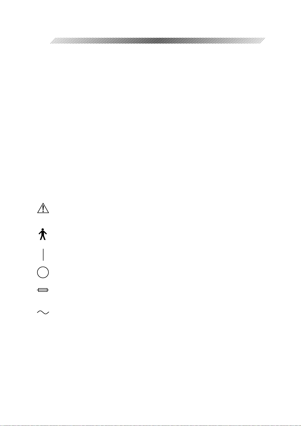
1.3 Symbol Information
This symbol on the instrument indicates that caution should be taken. Refer to the
Operator’s Manual before operating the instrument.
This symbol indicates that the instrument is classified as an instrument with a Type B
applied part.
This symbol on the power switch indicates that the power is ON.
This symbol on the power switch indicates that the power is OFF.
This symbol indicates the proper fuse rating of the device.
This symbol indicates that the instrument must be supplied only with an alternating
current.
Page 9
1 - 3
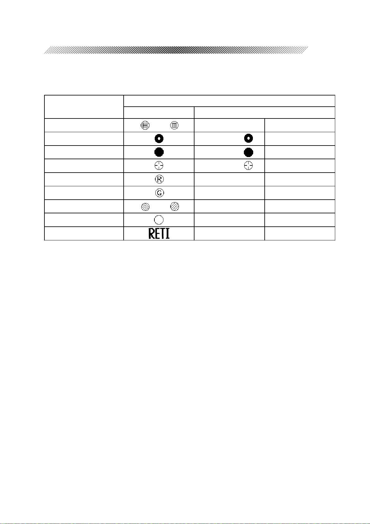
The symbols printed on the control box and shown on the display correspond to the symbols and
those names defined in ISO 10341 (Ophthalmic instruments - Refractor heads) as shown in the
following table.
Auxiliary lens
Marking
RT-2100 ISO10341
Red maddox rod or MR Maddox rods
Pinhole plate PH or Pinhole
Occluder BL or Occluder
PD check lens CL or Cross line
Red filter RF Red filter
Green filter GF Green filter
Polarizing filter or PF Polarization filter
Open aperture OA Open aperture
Lenses for retinoscope RL Retinoscopic lens
Page 10
§
2
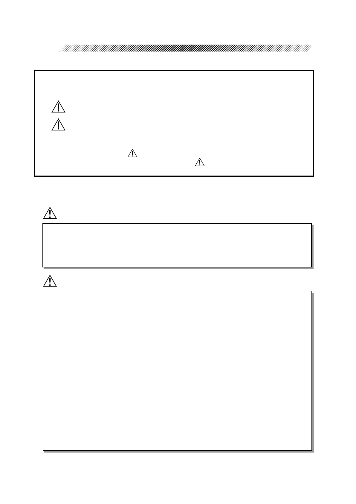
The following safety precautions should always be followed.
In this manual, Signal Words are used to designate a degree or level of safety alerting.
The definitions are as follows.
WARNING: Indicates a potentially hazardous situation which, if not avoided,
could result in death or serious injury.
CAUTION: Indicates a potentially hazardous situation which, if not avoided,
may result in minor or moderate injury or property damage.
Even cases mentioned in CAUTION may result in serious injury under certain
conditions. Be sure to observe the instructions of CAUTION.
2.1 Operation
SAFETY
WARNING
• When moving the refractor head in front of or away from the patient, make sure that there
are no obstacles in its path.
Inadvertent contact with a person or object could result in personal injury and/or damage
to the instrument.
CAUTION
• Never disassemble or tamper with the inside of the instrument.
This may result in an electric shock or an instrument malfunction.
• Be sure to use an electrical current which meets the power specification requirements.
If the line voltage is too high or too low , it may af fect the performance of the instrument
and may start an electrical fire.
• Always remove the power cord from the wall outlet by holding the plug. Never pull on
the cord.
This can damage the internal wires and may result in a short circuit, an electric shock or
a fire.
• If the internal wires of the power cord are exposed, the power to the instrument will be
inconsistent, or the plug will become extremely hot, indicating internal damage to the
cord. If this occurs, remove the cord from the outlet immediately. After checking to see
that no more smoke is being produced, contact your authorized distributor immediately.
If the instrument is not functioning normally , it may cause an electric shock or a fire.
Page 11
CAUTION
• Do not crush or squeeze the power cord with heavy objects.
If the power cord is damaged, it may cause an electric shock or a fire.
• Clean between the prongs of the power plug using a dry cloth every couple of months.
If the prongs are exposed to moisture or excessive dirt, the instrument may short circuit
or cause a fire.
• If you notice strange odors or smoke being emitted from the instrument, turn OFF the
instrument, and disconnect the power cord immediately. After confirming that smoke is
no longer being produced, contact your authorized distributor .
If the instrument is used under abnormal conditions, it may cause an electric shock or a
fire.
NOTE
2 - 2
• Do not touch the measuring windows.
Dirt or fingerprints on the measuring windows may affect the accuracy of the refraction
data.
• Be sure to wipe the forehead rest and face shields with a clean cloth and a diluted neutral
detergent solution before each examination.
2.2 Storage
NOTE
• Do not store the instrument in a place where it may be exposed to moisture or toxic
chemicals.
• Avoid storing the instrument in an area with excessive heat, humidity, or dust.
To preserve the appearance of the instrument, avoid direct exposure to sunlight.
Page 12
2 - 3
2.3 Installation
WARNING
• The refractor head weights 6.7 kg. Make sure that the refractor’s arm has been designed
to bear the weight.
Before attaching the refractor head to the arm, impose weight on the arm, and confirm
that the refractor head is stable during normal use.
• Be sure to secure the refractor head to the refractor arm with the set screw.
If the refractor head is dropped or falls, it could cause extensive damage and possible
injury.
NOTE
• Store the instrument in the following conditions.
Temperature: 10 - 40 °C
Humidity: 30 - 85 %
A dust free environment
Minimal exposure to direct sunlight
An area free of vibration
• Be sure to level the refractor head before use.
If it is not level, the accuracy of the refraction data may be affected. Level the refractor
head by turning the Leveling adjustment knob until the bubble is centered in the level.
• This instrument has been tested and found to comply with the limits for medical devices
to the IEC 60601-1-2: 1993, EN60601-1-2: 1994, Medical Device Directive 93/42/EEC.
These limits are designed to provide reasonable protection against harmful interference
in a typical medical installation. This instrument generates, uses and can radiate radio
frequency energy and, if not installed and used in accordance with the instructions, may
cause harmful interference to other devices in the vicinity . However , there is no guarantee
that interference will not occur in a particular installation. If this instrument does cause
harmful interference to other devices, which can be determined by turning the instrument
off and on, the user is encouraged to try to correct the interference by one or more of the
following measures:
- Reorient or relocate the receiving device.
- Increase the separation between the instruments.
- Connect the instrument to an outlet on a circuit different from that to which the other
device(s) are connected.
- Consult the manufacturer or field service technician for help.
Page 13
2.4 Wiring
CAUTION
• Be sure to use a (HOSPITAL GRADE) wall outlet equipped with a grounding terminal
in order to avoid an electric shock or fire in the event of a power leak.
• Be sure the plug is securely in place in the wall outlet.
Insecure connections may affect the operation of the instrument or create a fire hazard.
2.5 After Use
CAUTION
• If the instrument will not be used for an extended period, disconnect the power plug from
the wall outlet.
If the instrument is covered with dust and it takes on moisture, it may create a fire
hazard. Always use the dust cover supplied with the instrument.
2 - 4
NOTE
• When the instrument is not in use, turn OFF the power switch and put the dust cover on.
If the instrument is not covered for an extended period, the accumulation of dust may
affect the accuracy of the instrument.
2.6 Maintenance
NOTE
• Never use an organic solvent or abrasive solvent to clean the exterior of the instrument as
it may ruin the appearance.
• When the instrument is sent back to NIDEK for repair or maintenance, wipe the surface
(especially , the area where the patient’s skin contacts) of the instrument with a clean cloth
immersed in ethyl alcohol for disinfection.
Page 14

2 - 5
2.7 Disposal
NOTE
• Follow local governing ordinances and recycling plans regarding disposal or recycling of
device components.
Especially the disposal method of lithium batteries varies according to the government.
As the relay and control boxes have lithium batteries on the circuit boards, follow the
local governing ordinances and recycling plans when disposing of a circuit board with
lithium batteries.
• When disposing of packing materials, sort them by material and follow local governing
ordinances and recycling plans.
Page 15
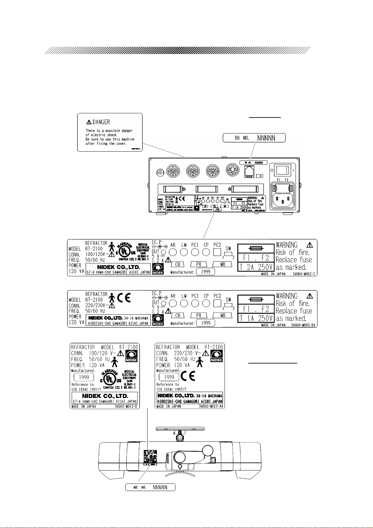
2.8 Labels
• Labels provide safety information about each part.
2 - 6
Relay box
For 100V area
For 200V area
For 100V area For 200V area
Refractor head
Page 16
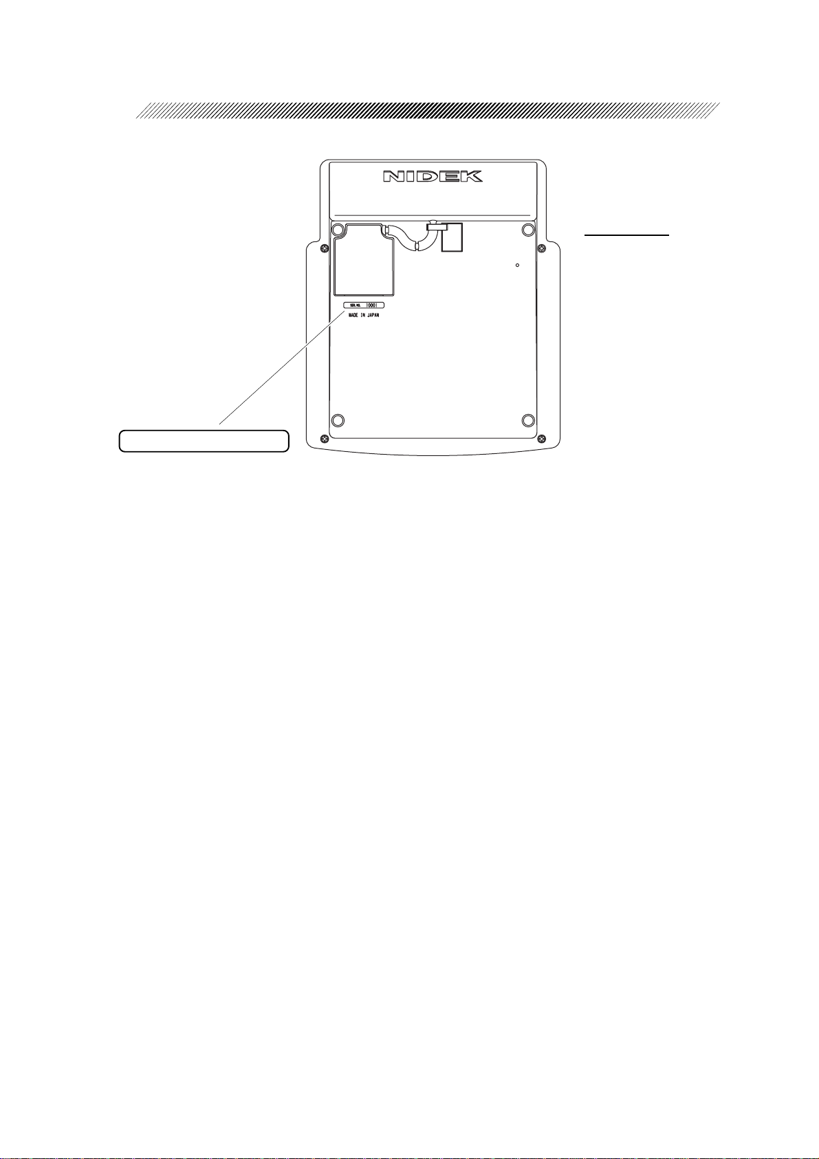
2 - 7
Control box
CB NO. NNNN
Page 17

2 - 8
Page 18

§
3
3.1 Refractor Head
Operator’s side
Near point card
Level
Forehead rest knob
CONFIGURATIONS
Near point rod
Level adjustment knob
Chart check mirror
Vertex distance check windows
Patient’s side
Measuring
windows
Lens banks
Forehead rest
Measuring windows
Face shields
Page 19
3 - 2
Measuring windows
Patients look at the chart through these windows.
Vertex distance check windows
Used to check the patient’ s VD (the distance
from a corneal vertex point to the lens).
The window has calibration markings of 12,
13.75, 16, 18 and 20 mm.
Forehead rest knob
Used to move the forehead rest forward and
backward in order to adjust the vertex distance (VD).
Level
Used to verify that the refractor head is level.
Turn the level adjustment knob until the air
bubble is centered in the level.
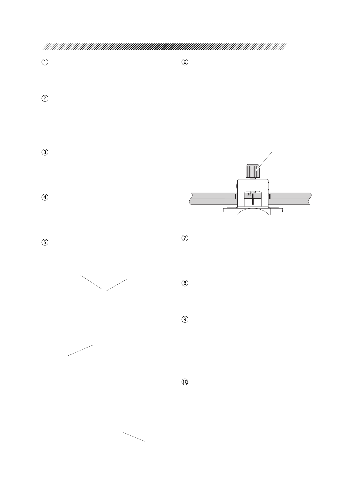
Near point rod
The distances from the patient’s eye to the
near point card is marked in inches and centimeters.
• The black line at the near point card holder
is aligned with the tick of the desired distance.
• The red number represents the power (diopter), the reciprocal of each distance in
meters.
Adjust the chart to a
desired distance from
the patient’s eyes and
tighten the knob to fix
the position.
Near point card
Used for Addition Power measurement.
Number of the chart
Chart
Name of the chart
on the rear side
The refracting distance is printed at the top
of the card.
Level adjustment knob
Used to adjust the level of the refractor head.
It can be inclined 2.5º toward the left or right
at the maximum.
Chart check mirror
An operator confirms the selected chart with
this mirror.
Forehead rest
Patient’s forehead should touch the rest during measurement. Clean it before each measurement.
See “8.1 Cleaning the Forehead Rest”. (p. 8-
1)
Face shields
Patient’s face touches the shields during measurement. Clean them before measurement.
See “8.2 Cleaning the Face Shields”. (p. 8-2)
Explanation of the chart
Page 20
3 - 3
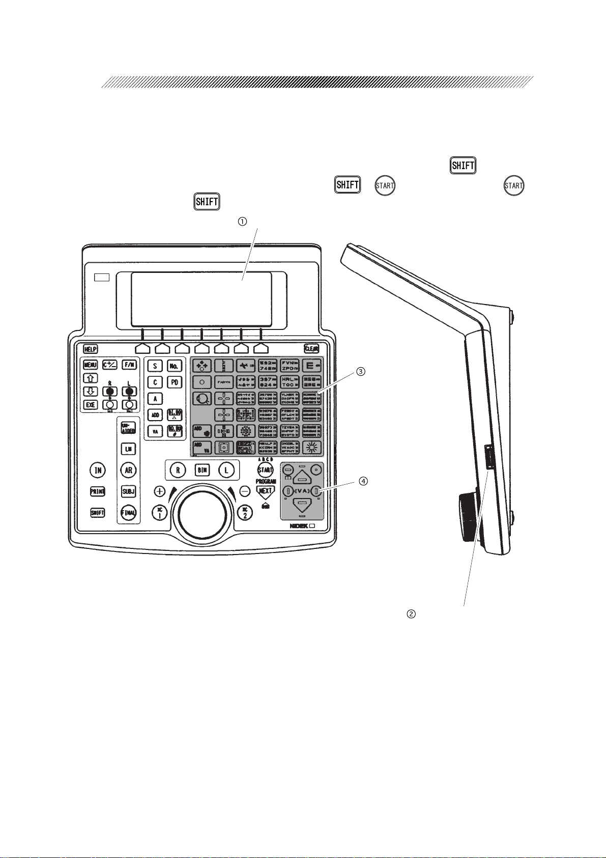
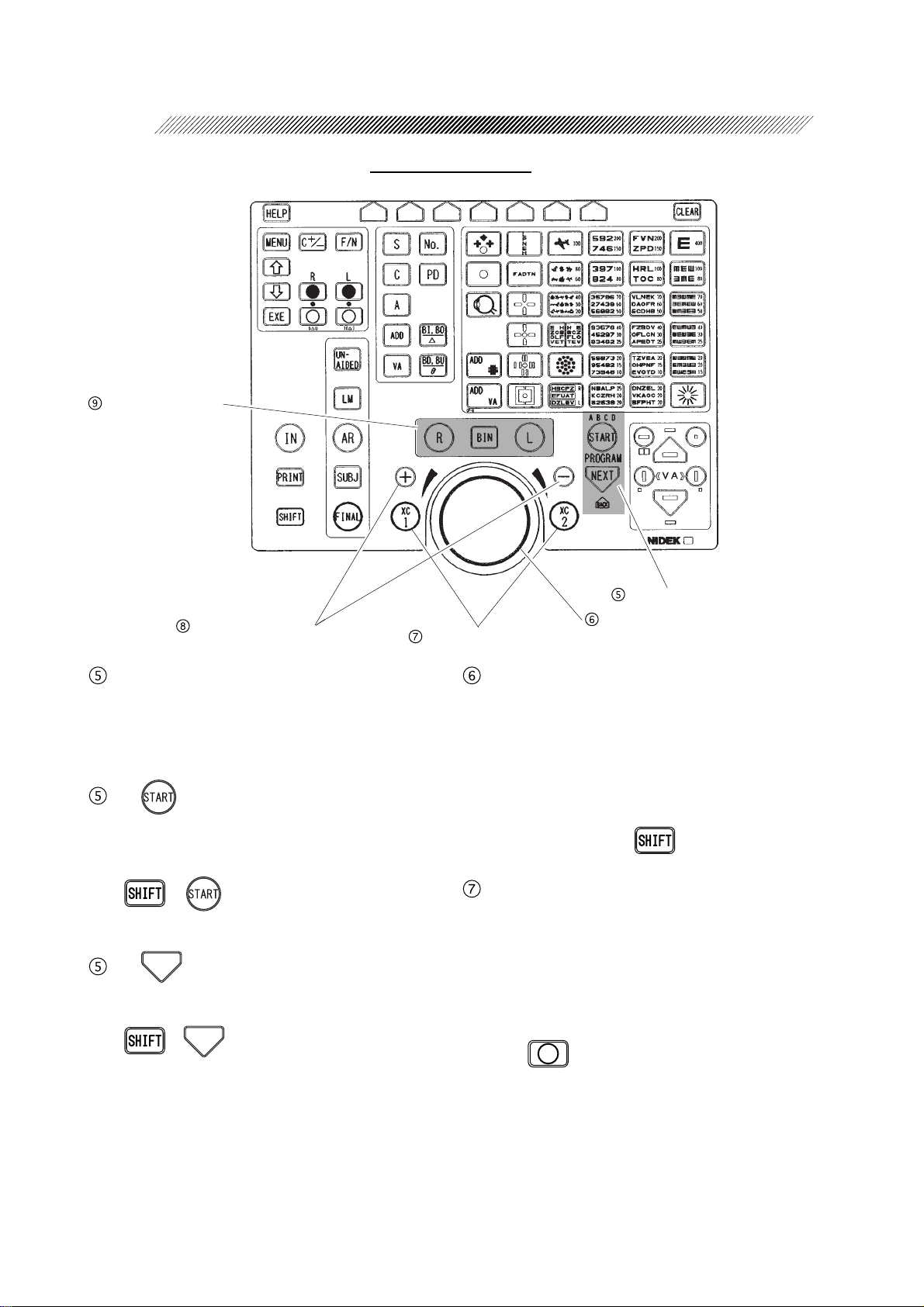
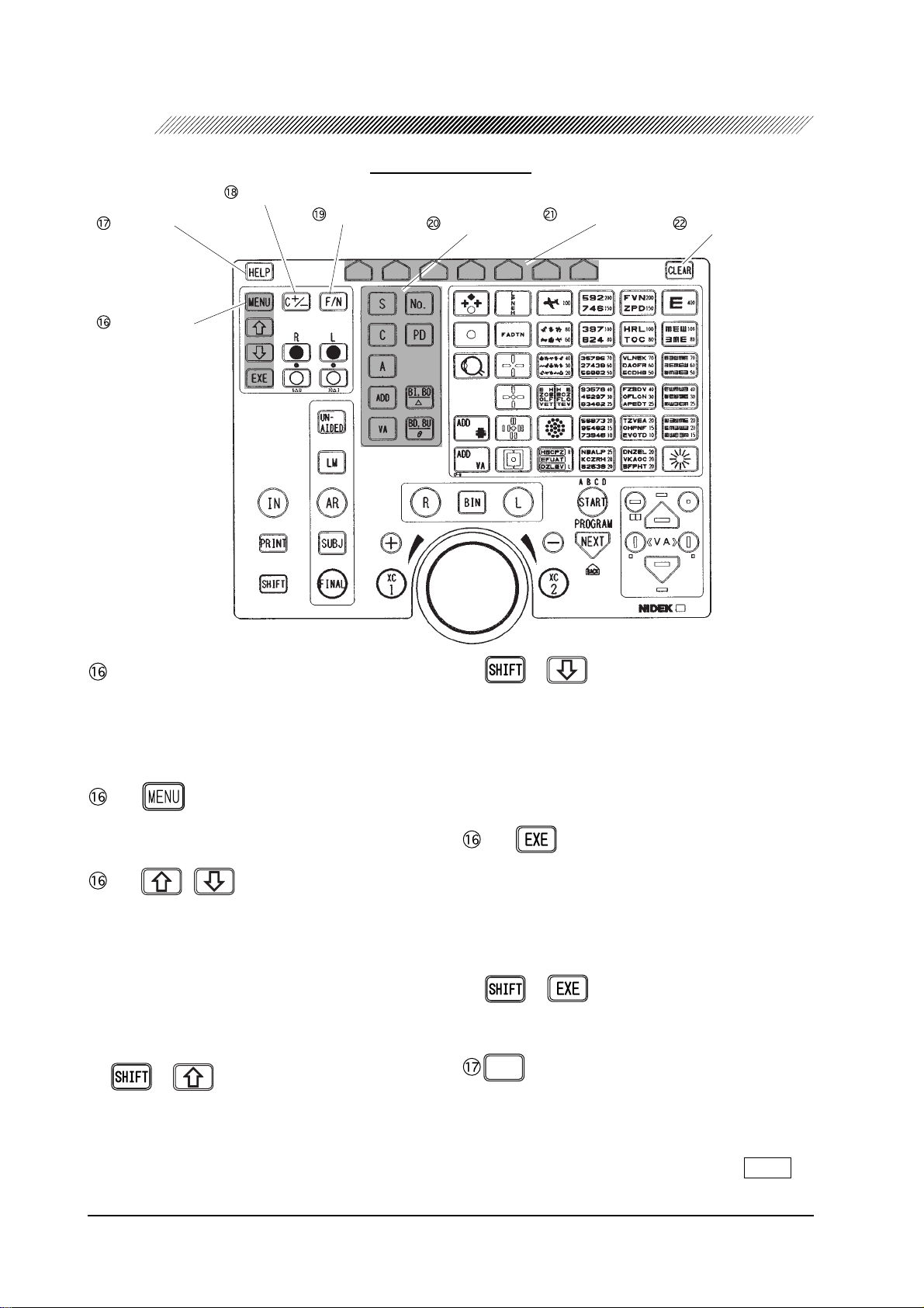
3.2 Control Box
The blue colored keys are used for basic operation.
* Some switches function differently when they are used in conjunction with .
In this manual, when you see instructions such as: “ + ”, it means “Press the
key while pressing the key.”
Display
Chart keys
Masking keys
Contrast adjustment knob
Page 21
3 - 4
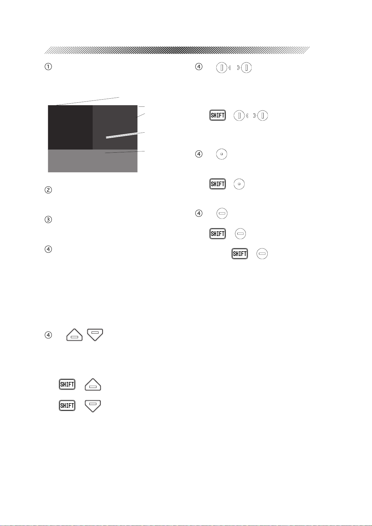
Display
Shows SPH, CYL, AXIS data and the chart
that is being presented.
Date
Time
Previous data window
(Sub-window)
Current data window
(Main window)
Present chart
Contrast adjustment knob
Used to adjust the contrast of the display.
Chart keys
Used to select charts.
Masking keys
Used to isolate any acuity line or letter on the
chart that has been selected.
To remove the mask, press any of the chart
keys.
VA (V isual Acuity) of the selected line or letter is shown at “VA” on the Main window of
the display .
- 2 ,
Used to isolate a vertical line on the VA chart.
• Used to move the isolation to the right or
left after the vertical line mask or a single
letter mask has been applied.
• + / ⇒ Isolates a single letter at the lower-left or lower-right corner of
a VA chart.
- 3
Used to isolate a single letter at the upperright corner of a VA chart.
• + ⇒ Isolates a single letter at the
upper-left corner of a VA chart.
- 4
Used to isolate a middle line of a VA chart.
• + ⇒ Adds the Red/Green filter
to a VA chart that has been selected.
Again, + ⇒ Releases the Red/
Green filter.
- 1 ,
Used to isolate a horizontal line (letters of the
same VA) on the VA chart.
• Used to move an isolation up and down after the mask has been applied.
• + ⇒ A horizontal line mask
will be applied to the top line of the chart.
+ ⇒ A horizontal line mask
will be applied to the bottom line of the
chart.
Page 22
3 - 5
Eye selection keys
Keys of Control Box
Value change keys
Cross cylinder keys
Program keys
For more information on using the programmed refraction sequence, see “4.5 Refraction with the Standard Program” (p. 4-12).
- 1
Starts a program.
• Press to start a programmed refraction sequence and activate the initial steps.
• + ⇒ Switches among program
modes (A, B, C, D, E) in order.
0':6
- 2
Used to progress through each step of a programmed refraction sequence.
• +
0':6
⇒ Allows the user to go back
to a previous step in the refraction program.
(This key combination is inoperative while
in the Final Fit mode.)
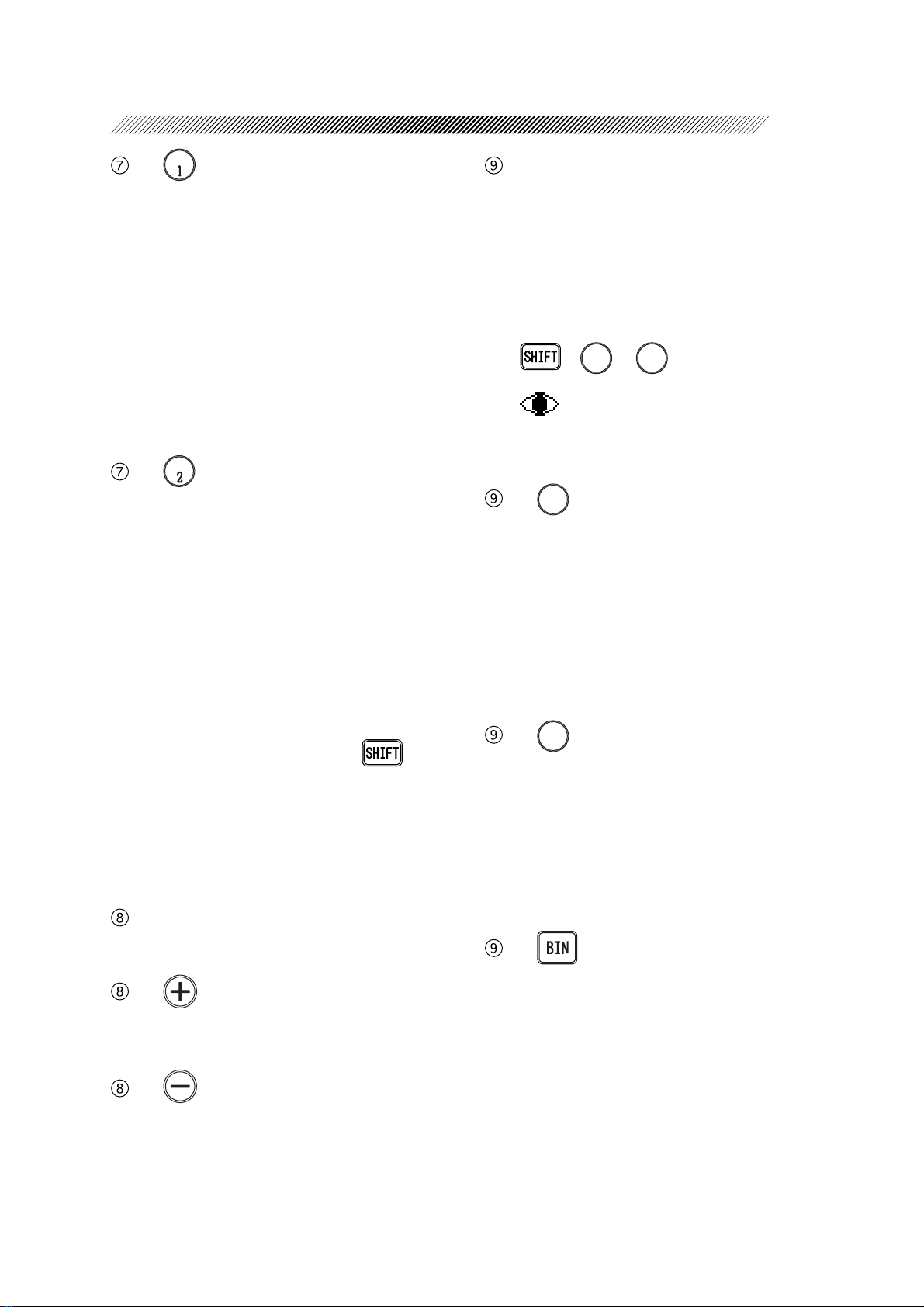
Program keys
Dial
Dial
Changes any highlighted value.
Turn it clockwise ⇒ The value changes to
the negative.
Turn it counterclockwise ⇒ The value
changes to the positive.
The highlighted value changes by turning the
knob while holding down.
Cross cylinder keys
Place a cross cylinder lens to refine axis or
Cylindrical Power.
When it is pressed during binocular tests, the
left measuring window is covered in order to
allow testing of the right-eye only.
T o perform the test with both windows open,
press of the covered-side window.
The 0.25 or 0.50 diopter lens should be selected in the “XC test” parameter of “Set parameter 1/5” screen prior to testing. A cross
cylinder lens will be inserted as follows unless “Auto” is selected instead of “XC test”
of “Set parameter 1/5”.
Page 23
:%
- 1
• During axis refinement, the cross cylinder
lens is inserted so that the minus axis is located at 45º from the minus axis position of
the cylinder lens.
• During Cylindrical Power refinement, the
cross cylinder lens is inserted so that the minus axis is located at 90º from the minus
axis position of the cylinder lens.
• When using the Prism refinement mode (BI/
BO), this switch can be pressed to clear out
the values and start at zero in the right eye.
:%
- 2
• During axis refinement, the cross cylinder
lens is inserted so that the minus axis is located at 135º from the minus axis position
of the cylinder lens.
• During Cylindrical Power refinement, the
cross cylinder lens is inserted so that the minus axis is located 0º from the minus axis
position of the cylinder lens.
• When using the Prism refinement mode (BI/
BO), this key can be pressed to clear out
the values and start at zero in the left eye.
• Press this key while pressing and the
time display changes to the stopwatch display . This enables you to measure how long
the test took and this function is sometime
used for special tests to be carried out in a
few seconds.
Value change keys
Provides the same function as the dial.
- 1
A value increases by increments of 1 each
time it is pressed.
3 - 6
Eye selection keys
Used to select right eye (R), left eye (L), or
both eyes (BIN) for subjective measurements.
• The measuring window of the non-selected
eye will automatically be covered. However, the occluder will not be inserted during binocular testing using prism lenses or
polarizing filters.
• +
nant eye.
will be shown next to R or L on the
measurement screen to indicate the dominant eye.
- 1
4
Leaves open or opens the right measuring
window and leaves closed or closes the left
measuring window. If a binocular testing
chart is selected and binocular testing is desired, the left measuring window will not be
covered and the right eye value is highlighted.
In this situation, only right eye data can be
adjusted.
- 2
.
Leaves open or opens the left measuring window and leaves closed or closes the right measuring window . If a binocular testing chart is
selected and binocular testing is desired, the
right measuring window will not be covered
and the left eye value is highlighted. In this
situation, only left eye data can be adjusted.
- 3
Keeps or makes both measuring windows
open. When changing values in this situation, data of both eyes can be changed to the
same values with each adjustment.
or
4
⇒ Specifies the domi-
.
- 2
A value decreases by increments of 1 each
time it is pressed.
Page 24
3 - 7
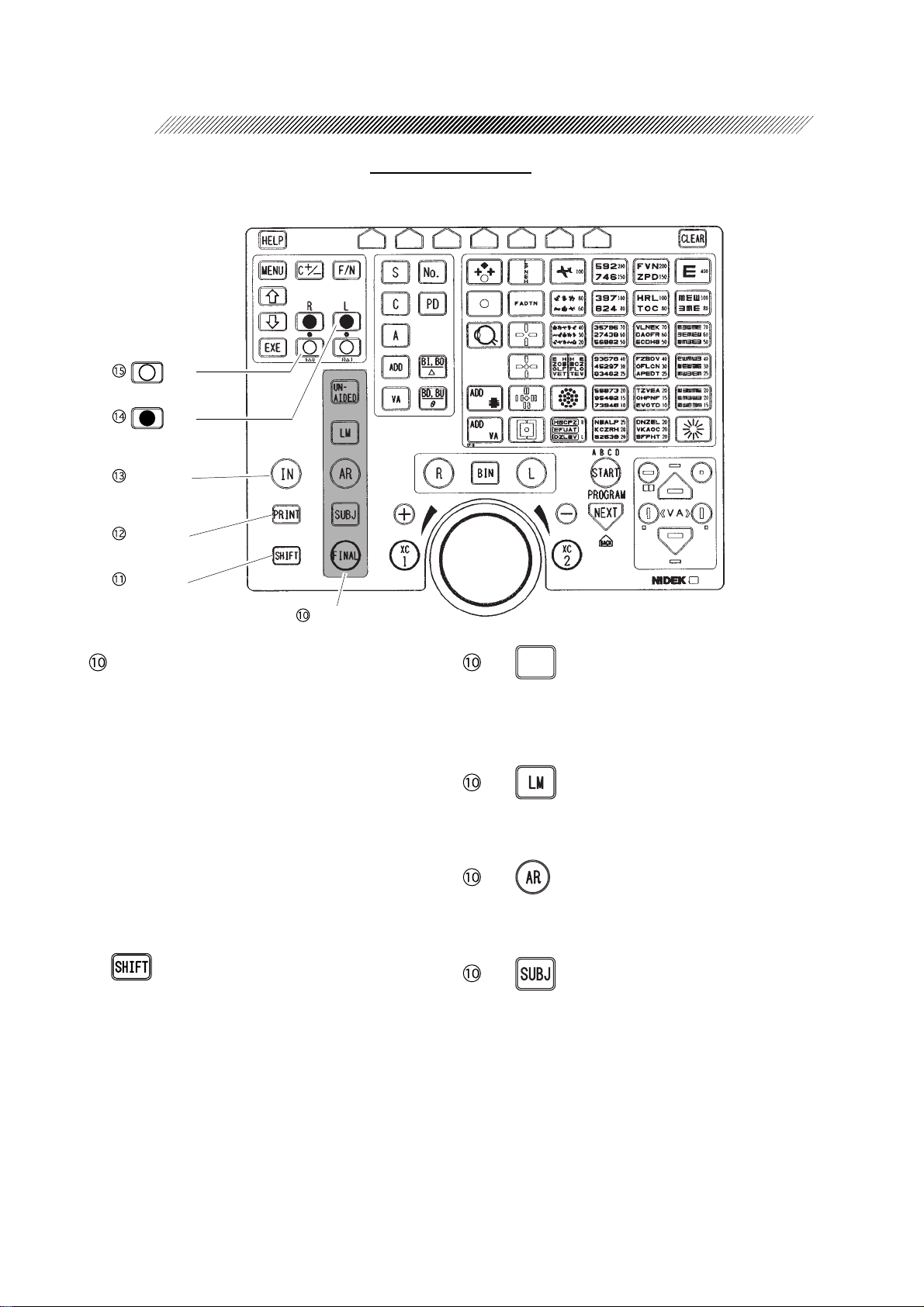
Keys of Control Box
Key
Key
Input key
Print key
Shift key
Data keys
Data keys
Used to specify the field for receiving data or
storing measurements.
Measurements in the specified field are shown
on the main window.
The specified field will be indicated at the upper-left corner of the main window.
If one of the data keys is pressed without receiving data from an AR or LM, then the current measurements which have been on the
main window, will be copied to the corresponding field to the selected data.
If one of these keys is pressed while holding
down, measurements on the screen will
be copied to the corresponding field regardless of whether any data has been received
and stored.
T o enter data to the RT-2100, see “4.3 Entering Data” (p. 4-2)
70
- 1
#+&'&
Used to open the field for measuring unaided
visual acuity. The corrective lens power in
the refractor head will be set to 0 D.
- 2
Used to open the field for receiving
lensometry data.
- 3
Used to open the field for receiving auto-refractometry or retinoscopic measurements.
- 4
Used to open the field for subjective refinement. When data is received from the AR or
LM, this field will automatically open. The
elapsed time starts to be measured from the
point where any data is entered to the SUBJ
field when the “Auto test time” parameter is
set at “Yes”.
Page 25
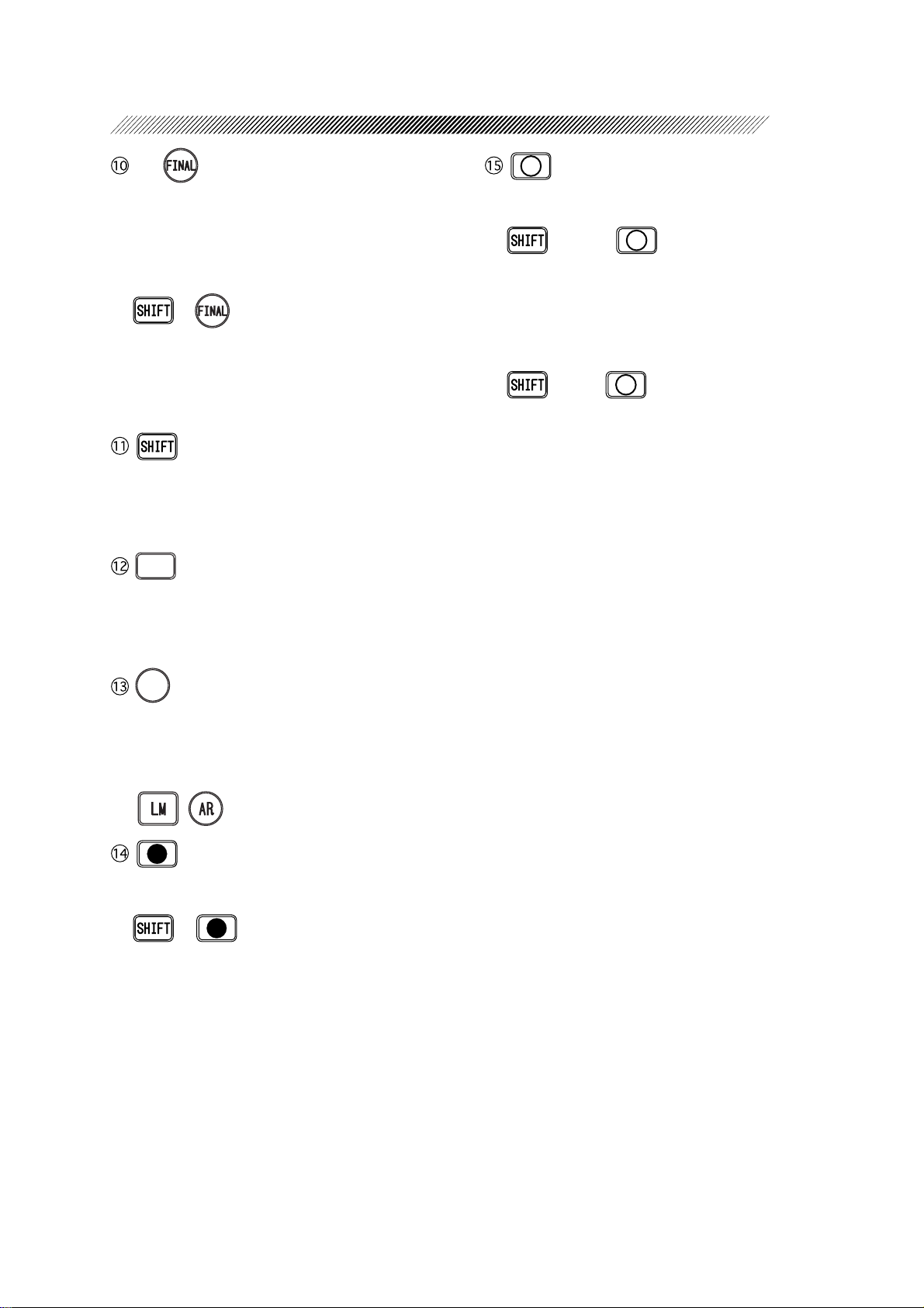
3 - 8
- 5
Used to open the field for obtaining a final
prescription and visual acuity.
The refined values are copied from the
“SUBJ” field and are adjusted to determine
final data.
+ ⇒
This will automatically activate the Final Fit
mode where Far Powers are automatically
adjusted. (See “4.7.1 Auto adjustment of Far
Powers”.) (p. 4-24)
While holding down this key, indication increments change or modes change when the
dial is turned or when a key is pressed.
24+06
Used to print out measurements or to export
data to an external computer . See “5.2 Printout” (p. 5-4)
Used to open the measuring window . Auxiliary lenses will be removed.
+ Right ⇒
6 ∆ base UP prism lens will be placed in the
right measuring window . It appears to the patient that one chart is dissociated into the upper and lower parts. Used to detect horizontal phoria.
+ Left ⇒
10 ∆ base IN prism lens will be placed in the
left measuring window . It appears to the patient that one chart is dissociated into the left
and right parts. Used to detect vertical phoria.
+0
Used to receive data from the LM or AR.
Press the key and make sure that the data No.
on the display is the same as the one on the
printout from the LM or AR. Specify either
( , ) with the data keys.
Used to close the measuring windows. Used
for monocular testing or cover testing.
+ ⇒ Insert a pinhole plate with
a diameter of 1 mm.
• The Focal depth of the eye becomes deeper.
• Can be used when visual acuity obtained
with the corrective lenses is below expectations. If the pinhole improves the patient’ s
VA, the eye may have an irregular astigmatism.
Page 26
3 - 9
Setting keys
C+/– key
Keys of Control Box
F/N key
Mode keys
Function keys
Clear key Help key
Setting keys
Used to open the field for changing parameter settings or programming refraction.
See “§5 OTHER FUNCTIONS”. (p. 5-1)
- 1
Used to open the “Set up menu” screen.
- 2 ,
Used to select a menu option.
These keys are also used to adjust the chart
position when the SSC-300/SSC-330/SSC350 is connected to the RT-2100.
When programming, they are used to select
the comments. See “5.1.2 Programming” (p.
5-2).
+ ⇒ *
2
Makes the intensity of the glare lamp higher
by one increment while the glare lamp is illuminated. The brightness, however, does not
change when the lamp intensity is the highest
even though these switches are pressed.
+ ⇒ *
2
Makes the intensity of the glare lamp lower
by one increment while the glare lamp is illuminated. The brightness, however, does not
change when the lamp intensity is the lowest
even though these switches are pressed.
- 3
Used to determine the selected menu options.
If the RT-2100 interfaces with the SSC-300/
SSC-330/SSC-350, this key is used to adjust
the chart position. See “4.4 Initial Setups”
(p. 4-11).
+ ⇒ *
2
Turns the glare lamp ON/OFF.
*'.2
Used to call up on-screen explanations and
instructions for the selected chart.
To cancel, press the key again or press the
function key which corresponds to .
END
*2 This function is available only when the optional glare lamp is attached to the connected SSC-
330.
Page 27
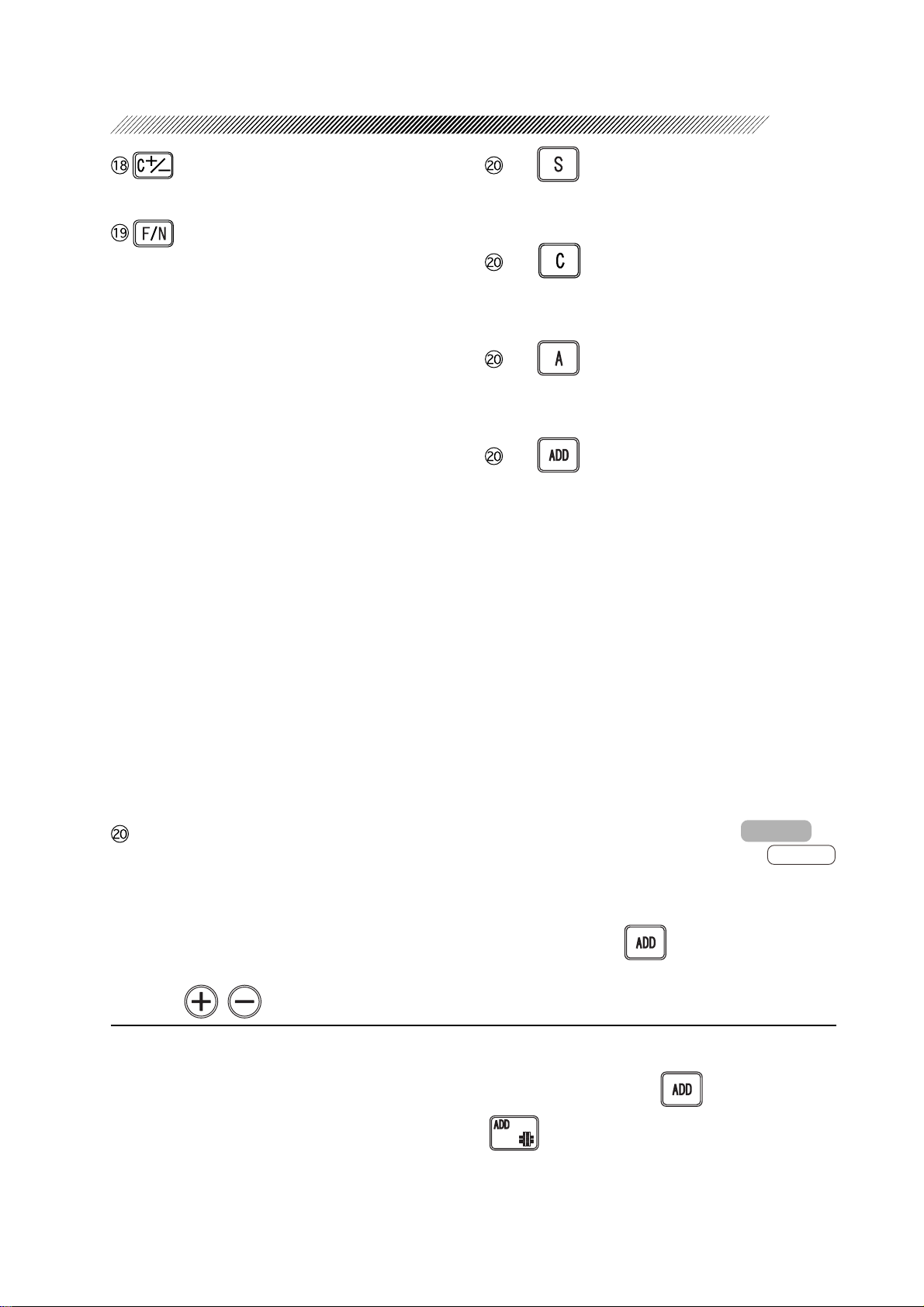
Switches Cylindrical Power to either + or –.
3 - 10
- 1
Places the system into the SPH mode which
allows Spherical Power to be adjusted.
Switches to either the Distance (Far) mode
or Near mode. The selected mode is indicated in the upper-right corner of the main
window as “FAR” or “NEAR”.
• The system will automatically operate in the
Far mode when the power is turned ON and
after data is cleared.
• The Near mode is used after distance vision has been refined and Addition Power
has been calculated in order to perform near
vision function testing such as relative accommodation and horizontal or vertical
phoria testing. When the Near mode is selected, both lens banks will converge to the
preset working distance of 40 cm (variable)
automatically.
• The ADD key will not work in the Near
mode. The Near SPH value will be calculated by adding ADD value to the distance
SPH value (distance SPH + ADD). It is
also possible to transfer the distance SPH
value alone into the Near mode by selecting the “SPH + ADD” option in the “SPH
Far → Near” parameter .
Mode keys
Selects the measurement field in which
measurements are to be refined (or changed).
Once the field is selected, a data field will be
highlighted, indicating that changes can be
made.
The measurement can be changed with the
dial or , .
- 2
Places the system into the CYL mode which
allows Cylindrical Power to be adjusted.
- 3
Places the system into the AXIS mode which
allows the cylindrical axis to be adjusted.
- 4
Places the system into the ADD mode which
allows the Addition Power to be adjusted.*
Both lens banks will automatically converge
to the preset working distance of 40 cm (variable). See the explanation of “Working dist.
(WD)” parameter. (p. 5-13).
• When the “Preset ADD” parameter is set to
“Yes”, the patient’s general age can be selected*4 and the expected spherical lens will
be inserted and Addition Power will be displayed.
• Each time the key is pressed, a spherical lens
with an Addition Power will be added or
removed alternately and the lens banks will
remain converged.
The reversed ADD indicator on
the main window will change to
and date indication will also change to
“ADD-OFF” showing that the lens is removed.
By pressing again, the Addition
Power indicator will be highlighted and the
addition power of the lens will be added.
3
*3 When the system is placed into the ADD mode during standard program (Program A) operation,
±0.5 D cross cylinder lens (minus axis: 90°) will automatically be placed into the measuring
windows. The ±0.5 D cross cylinder lens will not be inserted when is pressed during
non-programmed measurement.
To insert the ±0.5 D cross cylinder lens, press .
*4 The expected spherical lens with Addition Power will automatically be added according to the
selected age. See “Appendix. D Preset Addition Power”.
Page 28
3 - 11
After entering Addition Power, the working
distance indications appear and the desired
working distance can be selected with the corresponding function key .
The procedure for removing and setting Addition Power is the same as that for prism
lenses. See “4.3.5.5 Removing and replacing prism lenses”. (p. 4-9)
It is possible to switch fields among LM, AR,
SUBJ and FINAL on condition that the lens
banks are converged in the ADD mode.
• +
Used to place the system in the mode
which allows the values for NPC, NPA,
NRA and PRA*5 to be entered.
For the procedures of each test, see Ҥ6
METHOD OF SINGLE TESTS”. (p. 6-1)
- 5
Allows the user to manually enter visual acuity with the dial.
When AR or LM data has been entered and
“UNAIDED” or “LM” field key is pressed,
an expected VA chart will be presented.*
6
- 6
Allows the user to select a patient ID No.,
which will be printed out and can be used as
a communication ID for patient records in a
PC.
See “5.2.1 Changing an ID No.”. (p. 5-6)
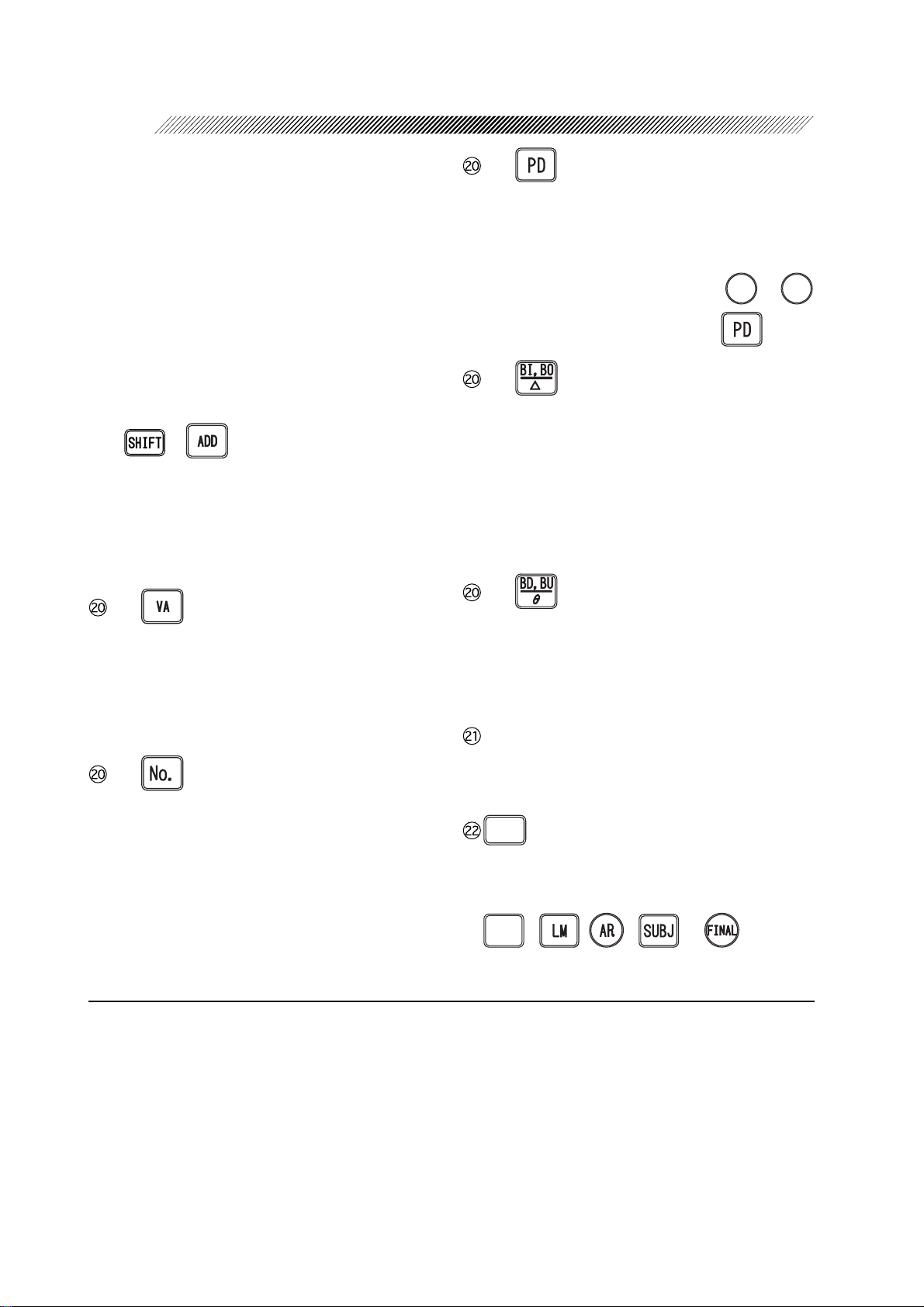
- 7
Displays PD measurement and allows the user
to adjust the PD measurement in the refractor head.
Monocular PD (1/2 PD)*7 ⇒ Adjustments
can be made after pressing either
or
4
.
while in the PD mode.
To exit from the mode ⇒ Press again.
- 8
Allows the user to adjust base IN/OUT prism
values for horizontal measurements. Either
rectangular coordinates or absolute values for
polar coordinates may be entered and adjusted. See “4.3.5 Setting prism lenses” for
procedure for adjusting Prism Power. (p. 4-
7)
- 9
Allows the user to adjust base UP/DOWN
prism values for vertical measurements. Either rectangular coordinates or angle for polar coordinates may be entered.
Function keys
Used to select functions displayed on the bottom of the main window.
%.'#4
Clears all the data displayed in each field, on
the measurement screen. To delete data in
each field, press this key simultaneously with
70
, , , or .
#+&'&
*5 NPC: Near Point of Convergence NPA: Near Point of Accommodation
NRA: Negative Relative Accommodation PRA: Positive Relative Accommodation
*6 The expected VA chart will be presented only on condition that the parameter “Preset VA” is
set to “1 letter” or “H. line”. For the type of the presented VA chart, see “Appendix. E Table
for VA values as presented on charts”.
*7 Even when the monocular PD for only one eye is changed, both the left and right lens banks
move concurrently .
Page 29
Keys of Control Box
* Only when using the SSC-350 TYPE T/TCG in combination with the RT-2100
3 - 12
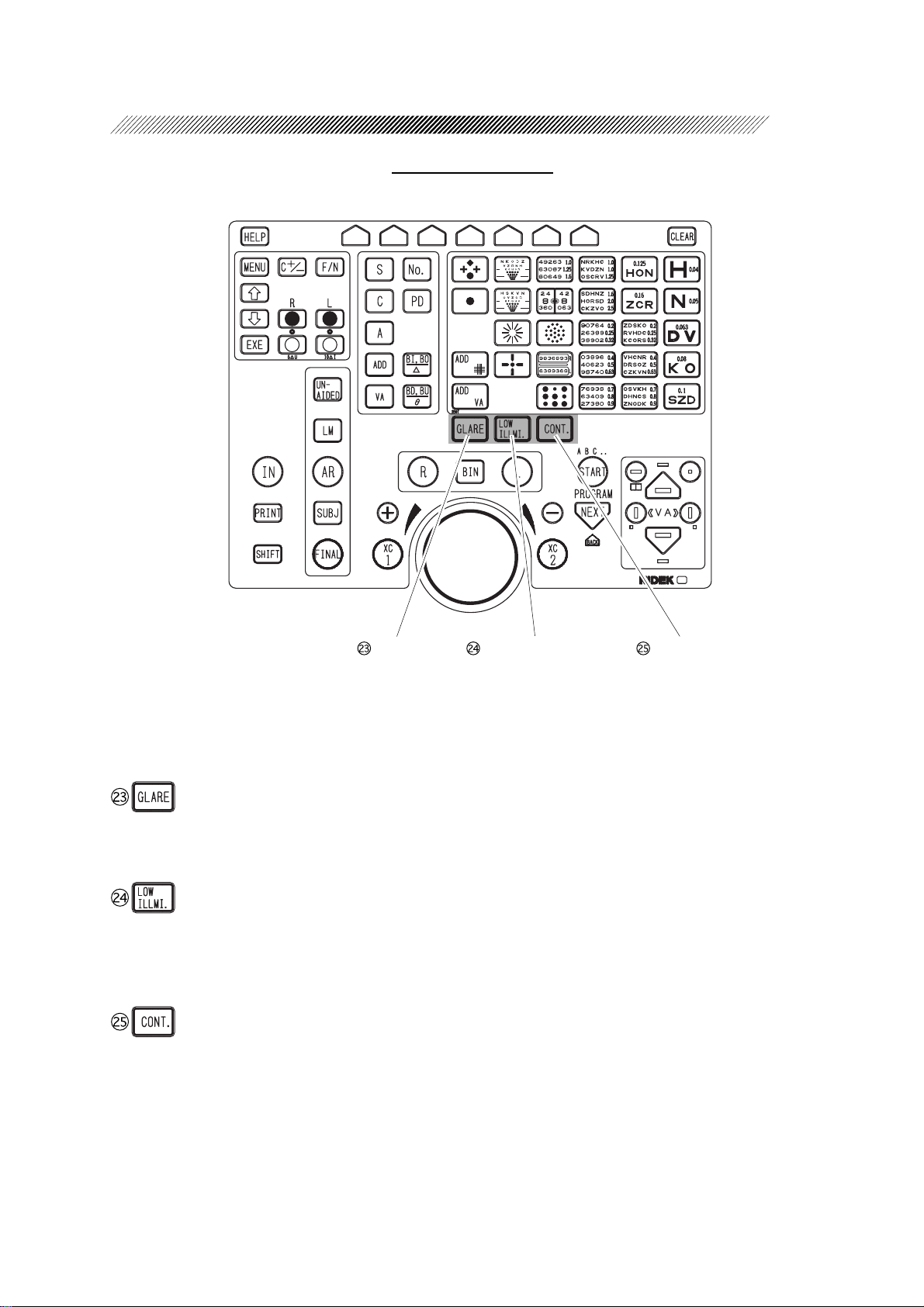
Glare key Low illumination key Contrast key
The following keys are used only when the RT-2100 is used in combination with the SSC-350
TYPE T/TCG.
Turns ON or OFF the glare lamp. (Only the
SSC-350 TYPE TCG)
Used to test at night.
Pressing the key switches between low
light and standard light illuminations.
Selects the contrast of charts.
Pressing the key changes the contrast in
the order of 25% → 12% → 6% → 100%
(standard light illumination). (Only the
SSC-350 TYPE TCG)
Page 30
3 - 13
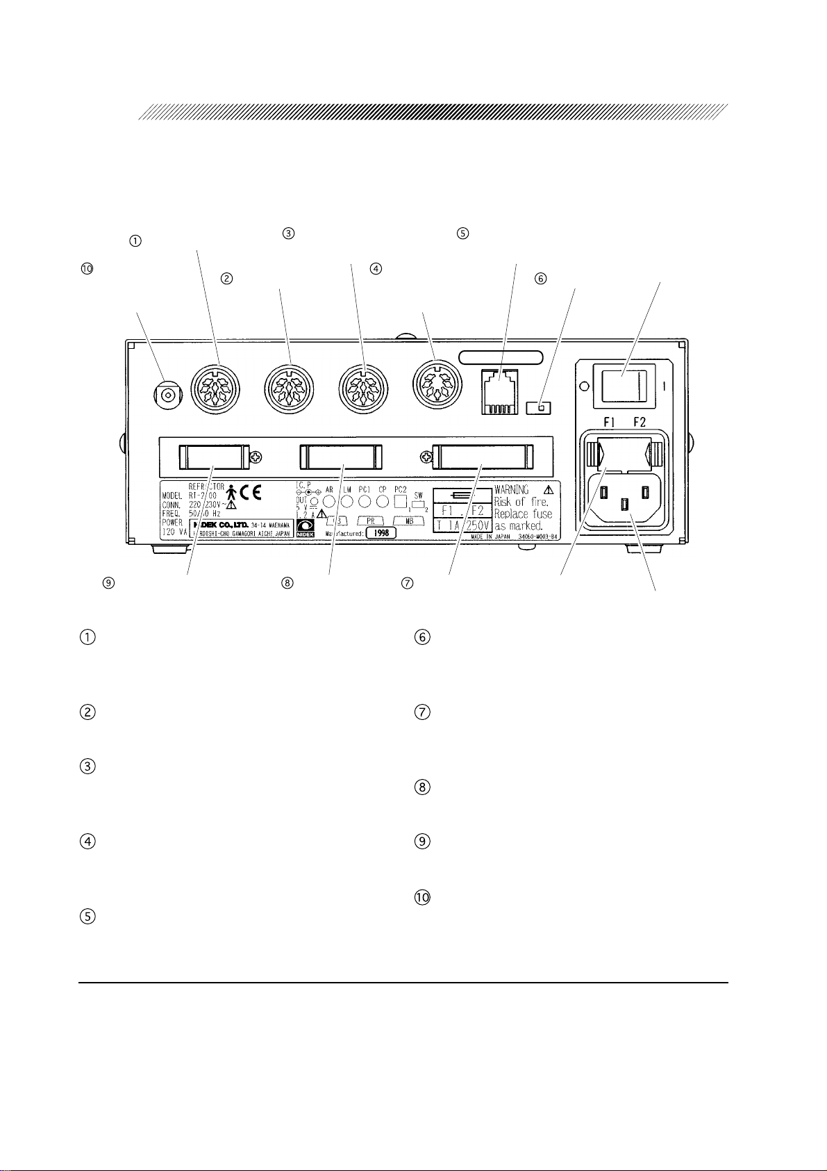
3.3 Relay Box
Normally, the relay box is contained in the system table.
Connector for AR*
Power connector
for IC card
Reader/Writer*
Connector for control box
8
Connector for AR*
8
Connector for LM*
8
Connector for external
computer*
Connector for
printer
8
8
Connector for
chart presenting
8
device*
Connector for
refractor head
Connector for
network (optional)*
Terminator
CB NO. NNNN
Fuse holder
8
Power switch
Power connector
Terminator
Port to connect the relay box to an Auto-Refractometer or IC card Reader/Writer.
Connector for LM*
8
Port to connect the relay box to a lensmeter.
Connector for external computer*
8
Port to connect the relay box to an external
computer.
Connector for chart presenting device
8
*
Port to connect the relay box to a chart presenting device.
Connector for network*
8
Port to connect the relay box to an external
Used only when more than one refractor is
used on a network. Normally, set at “1”.
Connector for refractor head
Port to connect the relay box to the refractor
head.
Connector for printer
Port to connect the relay box to the printer.
Connector for control box
Port to connect the relay box to the control box.
Power connector for IC card Reader/Writer*
Port to connect IC card Reader/Writer to a
power source.
computer for networking.
*8 Accessory equipment connected to the analog and digital interfaces must be certified according
to respective IEC standards (i. e. IEC 950 for data processing equipment and IEC 60601-1 for
medical equipment). Furthermore all configurations shall comply with the system standard
IEC 60601-1-1. Anyone who connects additional equipment to the signal input part or signal
output part configures a medical system, and is therefore responsible that the system complies
with the requirements of IEC 60601-1-1. If in doubt, consult NIDEK or your local representative.
8
Page 31

§
4
4.1 Operation Flow
4.2 Power-ON (p. 4-2)
4.3 Entering Data (p. 4-2)
4.3.1 Receiving data from the auto refractometers (p. 4-2)
→
→
4.3.2 Receiving data from the lensmeter (p. 4-3)
4.3.3 Manual entry with the dial (p. 4-4)
→
→
4.3.4 Entering data via an IC card (available only if the RT is equipped with the
IC card system) (p. 4-5)
→
4.3.5 Setting prism lenses (p. 4-7)
→
4.3.5.1 Switching coordinates between rectangular and polar (p. 4-7)
→
4.3.5.2 Setting rectangular coordinates (XY) (p. 4-7)
4.3.5.3 Setting polar coordinates (rθ) (p. 4-8)
→
→
4.3.5.4 Recording “Blur”, “Break” and “Recovery” (p. 4-8)
4.3.5.5 Removing and replacing prism lenses (p. 4-9)
→
4.3.5.6 Clearing prism data (p. 4-10)
→
OPERATING PROCEDURE
4.4 Initial Setups (p. 4-11)
4.5 Refraction with the Standard Program (p. 4-12)
4.5.1 Program A (p. 4-12)
→
4.6 Chart Presentation (p. 4-21)
4.6.1 Chart selection (p. 4-21)
→
4.6.2 VA chart maskings (p. 4-21)
→
4.7 Adjustment of Powers (Final Fit) (p. 4-24)
4.7.1 Auto adjustment of Far Powers (p. 4-24)
→
4.7.2 Fine adjustment after auto adjustment (Semi-auto adjustment) (p. 4-26)
→
→
4.7.3 Manual adjustment of powers (p. 4-27)
Printout
Power OFF
Page 32

4 - 2
4.2 Power-ON
Turn ON the power switch of the RT-2100 and a chart presenting device (CP-670/CP-690 or
SSC-300/SSC-330/SSC-350).
1. Power ON the connected chart presenting device.
2. Power ON the RT-2100.
Turn ON ( ) the Power switch on the relay
box.
The largest visual acuity (VA) chart will be
presented.
4.3 Entering Data
Enter objective measurements and/or lensometry data.
4.3.1 Receiving data from the auto refractometers
When the RT-2100 interfaces with the NIDEK Auto Refractometer (AR) and/or Auto Ref/
keratometer (ARK), the measured data will be automatically transferred to the R T-2100 by pressing
the “Print” button of the AR/ARK. The R T-2100 stores data in the memory of the relay box. If
the data is already in the memory, skip Steps 1 and 2 below.
1. Measure the patient’s eye with the AR/ARK.
See the AR/ARK operator’s manual.
2. After the measurement, press the “Print” button of the AR/ARK.
The measurements will be printed out and automatically stored in the relay box of the R T-2100.
The received data is registered by numbers, which can be found at the top of the printout. To
call up the stored data, use these numbers.
NOTE
• The maximum memory capacity is 9999 sequenced numbers. However, only the last
100 measurements will be memorized. Whenever the sequenced number exceeds
100, the data will be deleted beginning from the number 1.
• By connecting the optional memory box (RT6IF-80), the memory will be extended to
hold up to the most recent 150 measurements.
Page 33

4 - 3
3. Press
The number of the last reading from either
AR, ARK or LM will be shown on the display
as “Data No.”
4. Using the dial, change the “Data No.” to the
patient’s registration number. The number
is found at the top of the patient’s printout
of the AR or ARK measurements.
5. Transfer the data to the RT-2100.
Press .
• The refractor will be automatically set
• The KM data of the ARK measurements will
+0
.
according to the received data and the field
for subjective refinement automatically opens.
The elapsed time measurement from the point
where any data is entered to the SUBJ field
starts when the parameter “Auto test time” is
set at “Yes”. (Except when the elapsed time
measurement has already been started.)
not appear on the main window, but will
appear on the printout.
Data No. box
4.3.2 Receiving data from the lensmeter
When the NIDEK Lensmeter (LM) is interfaced with the R T-2100, the RT-2100 will automatically
receive the data from the instrument when the “Print” button of the LM is pressed. Data will be
stored in the memory of the relay box. If data is already in the memory, skip Steps 1 and 2.
1. Measure the patient’s glasses with the LM.
See the Operator’s Manual of the NIDEK Lensmeter (LM).
2. After measurement, press the “Print” button of the LM.
The measurements will be printed out and automatically stored in the relay box of the RT-2100.
The received data will be registered by numbers, which will be found at the top of the printout.
To call up the stored data, use these numbers.
Page 34

4 - 4
NOTE
• The maximum memory capacity is 9999 sequenced numbers. However, only the last
100 measurements will be memorized. Whenever the sequenced number exceeds
100, the data will be deleted beginning from number 1.
• By connecting the optional memory box (RT6IF-80), the memory will be extended to
hold up to the most recent 150 measurements.
3. Press
The number of the last reading from either the
AR, ARK or LM will be shown as “Data No.”.
4. Using the Dial, change the Data No. to the
patient’s registration number.
The number is found at the top of the patient’ s
printout of the LM measurement.
5. Transfer the data to the RT-2100.
Press .
The refractor settings will be automatically changed according to the received data and the
field for subjective refinement automatically opens. The elapsed time measurement from the
point where any data is entered to the SUBJ field starts when the “Auto test time” parameter is
set at “Yes”. (Except when the elapsed time measurement has already been started.)
+0
.
Data No. box
4.3.3 Manual entry with the dial
Entering values in the Manual Mode:
1. Specify the field for entering data.
Specify with or .
2. Specify the eye/eyes for entering data.
Press
3. Specify the mode.
Specify by pressing one of , , , , .
4. Enter the value.
Turn the dial to change the value.
for the right eye,
4
for the left eye, and for both eyes.
.
Page 35

(Entering values in the preset mode)
Using the dial, data may be manually entered without changing the refractor settings when the
system is placed in the preset mode.
1. Specify the field for entering data.
Specify with or .
4 - 5
2. Press
3. Specify the mode.
Specify by pressing one of , , , , .
The system will be placed in the preset mode.
4. Specify the eye/eyes for entering data.
Press
5. Enter the value.
Turn the dial to change the value.
6. Repeat Steps 3 to 5 until all data entry is complete. Then press
The refractor settings will now be automatically changed according to the preset data.
+0
.
for the right eye,
4
.
for the left eye, and for both eyes.
+0
again.
NOTE
• When data is manually entered into the “LM” or “UNAIDED” field by turning the
dial, it is necessary to select the starting data, “LM” or “AR” for the succeeding
subjective refinement and then press .
4.3.4 Entering data via an IC card (available only if the RT is
equipped with the IC card system)
By using the optional IC card Reader/Writer, data can be transmitted via IC card from the AR,
ARK or LM to the R T-2100 without connecting them directly.
However, the IC card does not carry keratometry (KM) data.
Page 36

4 - 6
[Writing AR, ARK, or LM data to an IC card]
A. Writing without printing out:
1. Measure the eye with the AR, ARK or measure the patient’s glasses with the LM.
2. Write data to an IC card.
Insert the card into the IC card slot of the AR, ARK or LM. After the data is written on the card,
the card will be ejected automatically.
B. Writing and printing out:
1. Insert the card into the IC card slot of the AR, ARK or measure the patient’s glasses with
the LM.
Be sure to insert it before measurements.
2. Measure the eye with the AR, ARK, or LM.
3. Press the “Print button” of the AR, ARK or LM.
Data will be printed out.
After the data is written, the card will be ejected automatically.
[Reading AR, ARK, or LM data on the RT-2100]
A. When there is no data in the control box:
When the mode is not shown in the upper-left corner of the main window, operate as follows.
1. Insert the card into the IC card slot of the system table.
After the data is read into the field for receiving LM or AR data, the IC card will be ejected
automatically. The data on the IC card will be cleared.
B. When there are some items of data in the control box:
When the mode is shown in the upper-left corner of the main window, operate as follows.
1. Insert the IC card into the IC card slot of the RT-2100.
2. Press
+0
.
3. Press either or .
After data is read into the field for receiving LM or AR data, the IC card will be ejected
automatically. The data on the IC card will be cleared.
Page 37

4.3.5 Setting prism lenses
4.3.5.1 Switching coordinates between rectangular and polar
Press the function key which corresponds to either XY or rθ .
This key toggles between rectangular (XY) and polar coordinates (rθ).
e.g.: R-eye: 1.0 ∆ BI, 1.0 ∆ BU ⇒ 1.40 ∆, BASE 45°
L-eye: 2.0 ∆ BO, 1.5 ∆ BD ⇒ 2.50 ∆, BASE 323°
4.3.5.2 Setting rectangular coordinates (XY)
1. Press .
Rotary prism lenses will be placed in the measuring windows.
The Prism Power will be highlighted on the main window.
4 - 7
2. Enter base in/out Prism Power.
Prism Powers (0.5 ∆ monocularly or 1.00 ∆ binocularly) may be entered by turning the dial.
Turn the Dial clockwise ⇒ Power increases to the BO (BASE OUT) side.
Turn the Dial counterclockwise ⇒ Power increases to the BI (BASE IN) side.
3. Press .
4. Enter base up/down Prism Power.
Prism Power (0.5 ∆ monocularly or 1.00 ∆ binocularly) may be entered by turning the dial.
Turn the Dial clockwise ⇒L-eye: Power increases to the BD (BASE DOWN) side.
R-eye: Power increases to the BU (BASE UP) side.
Turn the Dial counter clockwise ⇒L-eye: Power increases to the BU (BASE UP) side.
R-eye: Power increases to the BD (BASE DOWN) side.
Press or instead of the dial to change the power in 0.1 ∆ increments monocularly and
0.2 ∆ binocularly. Prism Power will change continuously while holding down the keys. (See p.
5-12)
To change the power in 2 ∆ increments monocularly and 4 ∆ binocularly, turn the dial while
pressing .
Page 38

4 - 8
4.3.5.3 Setting polar coordinates (r
1. Press .
Rotary prism lenses will be placed in the measuring windows.
The Prism Powers will be highlighted on the main window.
2. Change the prism absolute values.
Prism Powers (0.5 ∆ monocularly or 1.00 ∆ binocularly) may be changed by turning the dial.
Press or instead of the dial to change the prism in 0.1 ∆ increments monocularly and
0.2 ∆ binocularly.
3. Press .
4. Change the prism base direction.
Rotate the dial to change the value (1º monocularly or 2º binocularly).
The power changes in 5º increments by turning the dial while pressing .
θθ
θ
θθ
)
4.3.5.4 Recording “Blur”, “Break” and “Recovery”
When is pressed and “Blur/Break/Recov.”
of “Set parameter” has been set to “Yes”, the
display on the right will appear and the system
will be placed in the mode where the test to
detect phoria is performed.
• When the function key which corresponds to
PHOR is pressed, DIV will appear on the
display and the system will go into the mode
where the negative-relative convergence
(divergence) test is performed.
The measuring windows open and Prism
Power is 0.00 ∆. It is possible to enter Blur,
Break and Recovery values in this mode.
Page 39

• When the function key which corresponds
to DIV key is pressed, CONV will appear
on the screen and the system will go into the
mode where the positive relative convergence
test will be performed. The measuring
windows open and Prism Powers indicate
“0.00 ∆”.
• When the function key which corresponds
to CONV key is pressed, PHOR will appear
on the screen and the system will go back to
the mode for phoria testing. If the Prism
Powers have been set in the test, they will be
shown in the main window at this point.
• When a function key, which corresponds to
BLUR , BREK and RECV is pressed, the
key is highlighted and the base in/out Prism
Powers are stored.
4 - 9
• When the function key which corresponds to the highlighted BLUR , BREK and RECV is
pressed again, the stored power will be cleared and the function key will no longer be
highlighted.
For the procedures of the tests and value entry, see “6.6.14 Negative relative convergence test”
(p. 6-29) and “6.6.15 Positive relative convergence test” (p. 6-30).
4.3.5.5 Removing and replacing prism lenses
The rotary prism lenses can be instantly removed or set with a press of one key.
Press or again. While the rotary prism lenses are placed in the measuring
windows:
• The rotary prism lenses will be removed from the measuring windows.
• The reversed indication on the Main window will change to . The date
indication will change to ∆ - OFF , indicating the absence of rotary prism lenses.
• When is pressed, the BI, BO, or PRISM value is changeable.
When is pressed, the BD, BU or BASE value is changeable.
By pressing or again, the rotary prism lenses will be placed again.
Page 40

4 - 10
4.3.5.6 Clearing prism data
Prism Power of the right eye and left eye can be cleared separately .
Press :% ⇒ Prism Power of right eye will be cleared.
Press :% ⇒ Prism Power of left eye will be cleared.
Page 41

4.4 Initial Setups
1. Place the refractor head in front of the patient’s eyes.
1) Clean the forehead rest, face shields, and measuring windows prior to testing a patient. See
“§8 MAINTENANCE”. (p. 8-1)
2) Instruct the patient to lean against the forehead rest and look through the measuring windows.
2. Press .
The lenses for PD adjustment will be placed in the measuring windows and the front surface of
the patient’s eye will be illuminated.
3. Observe the patient’s eyes from the operator’s side.
Check to see that both the patient’s left and right eyes are located in the center of each measuring
window.
A. If eyes are not aligned horizontally , adjust the PD by turning the dial.
4 - 11
B. If eyes are not aligned vertically, attempt to reposition the patient. Instruct the patient to
straighten his/her head.
NOTE
• Even when the monocular PD for only one eye is changed, both the left and right
refractor heads move concurrently.
4. Adjust the vertex distance by turning the forehead rest knob.
1) Look through the VD check windows.
The windows are located on both sides of
the refractor head for observation of the
vertex distance. Align the longest line (13.75
mm mark) so that it appears in the “notch”
of the window.
2) Turn the forehead rest knob until the apex
of the patient’s cornea is aligned with a
desired calibration marking.
VD 20 mm
VD 18 mm
VD 13.75 mm
VD 16 mm
VD 12 mm
5. Press again.
The system will exit from the PD mode.
Adjust the chart position as follows only when the refractor (RT-2100) is secured to the NIDEK
motorized arm.
Press . The chart position will be adjusted according to the refractor’s height.
Page 42

4 - 12
4.5 Refraction with the Standard Program
With Program A, the system automatically calculates the subjective correction and final data.
4.5.1 Program A
Containing unaided and aided visual acuity tests, this program uses the Final Fit (Auto adjustment
function) to automatically adjust a prescription to suit the patient.
1. Specify Program A at “Program” in the “Set parameter”.
See “5.5 Parameter Settings”. (p. 5-10)
It is also possible to specify the program with the - combinations.
2. Enter objective measurements (AR data) and lensometry (LM) data if any .
See “4.3 Entering Data”. (p. 4-2)
3. Instruct the patient to look at the presented chart through the measuring windows of the
refractor.
Or occlude the left eye without using the refractor .
4. Perform the unaided visual acuity test.
Follow Steps 3 to 7 of “6.1 Unaided Visual Acuity Test” (p. 6-1)
5. Perform the aided visual acuity test.
See “6.2 Aided V isual Acuity Test” (p. 6-2).
6. Press .
The field for performing subjective measurement will open.
7. Press
An occluder will be placed in the left measuring window.
.
4
Page 43

8. Start Program A.
1) Press .
2) Instruct the patient to read the chart.
If the patient can not read the letters, it is
possible that the entered AR data is
incorrect, or the patient has some
abnormalities.
9. Perform the Red/Green test to refine
Spherical Power.
4 - 13
1) Press
Automatically SPH +0.50 D will be added
to “fog” the vision. The Red/Green chart
will be presented.
2) Turn the dial to release the “fog” one
increment at a time until the sharpness of
the letter on the red side and the green side
appear equal.
Letters on the red side are sharper.
→ Turn the dial clockwise one increment.
Letters on the green side are sharper.
→ Turn the dial counterclockwise one
0':6
.
increment.
NOTE
• Spherical refinement is performed, to bring the circle of least confusion onto the retina
before performing the following XC test for cylindrical refinement.
If the patient cannot see the red and green sides equally, turn the dial until the green
side is sharper.
Page 44

4 - 14
10. Refine Cylindrical axis.
1) Press
0':6
.
The dot chart will be presented.
A cross cylinder (XC) lens will be placed.
The type of the XC lens will be indicated as
AUTO , ±0.25 and ±0.50 . The placed
XC lens can be switched to other types with
the corresponding function key which is
located just below the indication.
2) Refine Cylindrical axis with the cross
cylinder lens.
• When specifying XC:
Ask a patient, “Which set of dots is
clearer, chart 1 or chart 2 ?”
:%
The chart 1 - presented by pressing
The chart 2 - presented by pressing
:%
If chart 1 is clearer
→Turn the dial counterclockwise one
increment. (Or press .)
If chart 2 is more clear
→Turn the dial clockwise one
increment.
(Or press .)
Repeat the above processes until both
charts appear equal.
• When specifying Auto XC:
Both chart 1 and chart 2 will be presented
simultaneously. Each chart position is
shown in the lower-left corner of the
display.
If chart 1 is clearer
→ Turn the dial counterclockwise one
increment. (Or press .)
If chart 2 is clearer
→Turn the dial clockwise one increment.
(Or press .)
Repeat the above processes until both charts appear equal.
Page 45

11. Refine Cylindrical Power.
4 - 15
1) Press
0':6
.
The axis of the cross cylinder lens (XC lens)
will be shifted.
2) Refine Cylindrical Power with the XC lens.
Follow the same procedure as 2) of Step 10.
12. Perform the Red/Green test to refine
Spherical Power.
1) Press
0':6
.
Automatically SPH +0.50 D lens will be
added to “fog” the vision. The Red/Green
chart will be presented.
2) Turn the dial to release the “fog” one
increment at a time until the sharpness of
the letters on the red side and the green side
appear equal.
Letters on the red side are sharper.
→ Turn the dial clockwise one increment.
Letters on the green side are sharper.
→ Turn the dial counterclockwise one
increment.
NOTE
• If the patient cannot see the red and green sides equally, turn the dial until the red side
appears sharper to avoid overminusing.
13. Adjust Spherical Power to the highest
possible positive value with the best possible
visual acuity.
1) Press
The isolated 20/20 line will be presented.
0':6
.
2) Use or to check the best possible
visual acuity .
Page 46

4 - 16
3) Adjust Spherical Power to the highest positive value with the best possible visual acuity.
Turn the dial counterclockwise to add SPH +0.25 D. If the chart appears to blur, turn the
dial clockwise one increment.
Subjective refinement of the right eye is complete.
14. Press
.
.
The right measuring window will automatically
be covered.
15. Follow the same procedure as Steps 8 to 13
to test the left eye.
Subjective refinement of the left eye is
complete.
16. Perform the binocular balance test.
1) Press
0':6
.
Polarizing filters will be placed in the
measuring windows;
Right eye 135º & left eye’s 45º
When the visual acuity is 20 or better,
positive power will be automatically added
to SPH to “fog” the vision. (See the “Fog
for Balance” parameter. [p. 5-13])
2) Adjust Spherical Power until the top and
bottom lines appear equally clear .
The top line is clearer.
→Press
and turn the dial
4
counterclockwise one increment.
The bottom line is clearer.
→Press
and turn the dial
.
counterclockwise one increment.
Binocular balance is achieved when the
patient can see both lines equally.
Unaided and corrected VA are shown by
pressing
or ..
4
Page 47

NOTE
• If the patient cannot see both lines equally ,
allow the dominant eye or the eye whose
LM data is higher to see clearer .
Binocular refinement is now complete.
17. Perform the stereo test.
4 - 17
1) Press
Polarizing filters will be placed in both
measuring windows.
Polarization angle:
The stereo test chart will be presented.
The fog which has been applied during the
binocular balance test will automatically be
released.
2) Confirm that the patient can see four sets of
lines stereoscopically .
Enter stereoparallax by pressing a corresponding function key.
For a patient who cannot see those lines stereoscopically, perform the binocular function
test as necessary. See “6.6 Binocular Vision Function Test”. (p. 6-7)
If a patient has stereoscopic vision with a high accuracy (normally 1´) and has no symptoms
of headache or eye strain, the patient’s phoria is usually negligible.
(If a patient can recognize the stereoscopic difference between the lines next to a circle and
star, his/her stereoparallax is 1´.) In this case, it is possible to skip the phoria, negative
relative convergence, and positive relative convergence tests.
* The stereo chart differs depending to the chart presenting device. See “6.6.10 Stereo test”.
0':6
.
Right eye 135° & left eye : 45°
(p. 6-25)
18. Adjust the power for spectacle correction.
NOTE
• When using the auto adjustment function, use the - combination after
pressing
0':6
. See “4.7 Adjustment of Powers” (p. 4-24).
Page 48

4 - 18
1) Press
0':6
.
2) Press or to present a desired
visual acuity chart.
3) Adjust the correction to the highest positive
power with the best possible visual acuity.
19. Check the visual acuity with the current correction (Final value for prescription).
If necessary, remove the refractor head and place the “FINAL” data in a trial frame to confirm
that the patient has the best corrected visual acuity with this lens combination.
1) Press
.
4
2) Check the visual acuity of the patient’s right eye.
Press or to change the isolated line.
3) Press
.
.
4) Check the visual acuity of the patient’s left eye.
Press or to change the isolated line.
5) Press .
6) Check binocular visual acuity.
Press or to change the isolated line.
20. Compare the lensometry (LM) data with the FINAL data.
1) Press .
Lensometry data will be placed in the measuring windows.
Ask the patient, “Which lens is more clear and comfortable ?”
Program A is complete if a near vision test is unnecessary. Go to Step 24.
Page 49

21. Measure Addition Power.
4 - 19
1) Press
2) Enter the patient’s age.
Select the patient’s age with the function key.
(See Appendix. D.)
Be sure to set the “Preset ADD” parameter
of “Set parameter” to “Yes” in advance.
The lens banks will be converged and fused
cross cylinder lenses (minus axis 90º) will
be placed in the measuring windows.
3) Pull down the near point rod and set the near
point card at a desired distance (normally
set at 40 cm).
4) Place the cross-grid chart on the near point
card in front of the patient.
0':6
.
5) Ask the patient, “Which lines are sharper, the horizontal or vertical ones? Or are they about
the same?”
The horizontal lines are sharper. → Turn the dial counterclockwise one increment until the
sharpness of both lines appears equal.
The vertical lines are sharper. → Turn the dial clockwise one increment until the sharpness
of both lines appears equal.
The sharpness of both lines are equal. → It is not necessary to change Addition Power .
NOTE
• If the patient cannot see the lines equally sharp, turn the dial until the horizontal lines
appear a little sharper .
Page 50

4 - 20
22. Test the patient’s near vision.
1) Press
0':6
. The fused cross cylinder lenses
will be removed.
2) Reverse the near point card and place the
letter chart in front of the patient.
3) Instruct the patient to read the smallest line
possible.
The values displayed on the screen at this
point will be recorded as the final data for
the prescription.
Program A is now completed.
23. Print out the prescription.
Press
24+06
.
24. Place the FINAL prescription lens in a trial frame if necessary.
Page 51

4.6 Chart Presentation
4.6.1 Chart selection
To present a desired chart, press the key corresponding to the chart.
The selected chart will be displayed on the display of the control box.
4.6.2 VA chart masking
To use the mask, press one of the masking keys on
the control box.
• How to use the vertical line mask
Press or .
While the vertical line is isolated;
Press or .
⇒ Isolation will move to the left or right.
If the isolation is on a column at one side
of the chart, short beeps will sound and it
will skip to the column of the other side of
the chart when the key is pressed again.
4 - 21
Masking keys
Press or .
⇒ Isolation moves up or down.
NOTE
• For the chart with four columns on the SSC-300/330, the vertical isolated line can only
be moved between the two columns in the middle.
• For the chart with five columns on the CP-670, the vertical isolated line can only be
moved between the leftmost, middle and rightmost columns.
• How to use the horizontal line mask
Press . ⇒ Only the top line will be
isolated.
Press . ⇒ Only the middle line will be
isolated.
Press . ⇒ Only the bottom line will be
isolated.
Page 52

4 - 22
While a horizontal line is isolated;
Press or . ⇒ Isolation will move up
or down.
• How to use the single letter mask
Press .
⇒ Only the letter in the upper-right corner of
the chart will be isolated.
Press and .
⇒ Only the letter in the upper-left corner of
the chart will be isolated.
Press and .
⇒ Only the letter in the lower-left corner of
the chart will be isolated.
Press and .
⇒ Only the letter in the lower-right corner of
the chart will be isolated.
While a single letter is isolated;
Press or .
⇒ Isolation will shift to the left or right.
When the key last pressed is pressed again
to shift it in the same direction with the
isolation located on one side of the chart,
short beeps will sound and it will skip to
the other side of the chart.
Press or .
⇒ Isolation moves up or down.
• How to use the Red/Green filter
Press and .
Red/Green filter will cover the presented VA
chart.
While the Red/Green filter is applied;
Press or .
⇒ The presented VA chart will change to
another.
Press and .
⇒ The filter will be released.
• How to release the masks and filter
By pressing any chart button, the applied mask
or filter will be released.
Page 53

Chart presentations using each masking key
(When using masking keys only)
4 - 23
Chart presentations using each masking key
(When using in combination with the masking keys)
Page 54

4 - 24
4.7 Adjustment of Powers (Final Fit)
This system provides an auto adjustment and a semi-auto adjustment function in which Spherical
and Cylindrical Powers are adjusted to the values that are comfortable for patients. In auto
adjustment, values are calculated from the subjective data, taking into consideration lensometry
data, the patient’s ability to adapt to correction (age), and the type of refractive error (myopia,
hyperopia, astigmatism, oblique astigmatism, anisometropia).
In semi-auto adjustment, the operator can manually change the values calculated in auto
adjustment.
In auto adjustment, the Final Fit is programmed to calculate much lower powers than an average
prescription. This is done intentionally to avoid overminusing the patient. It is necessary, after
auto adjustment, to perform semi-auto adjustment to ensure a proper final prescription.
NOTE
• Regard the values obtained in the Final Fit (auto adjustment function) only as a guide
for determining a final prescription. The final prescription should be determined by
the operator according to the patient’s responses.
• When using the auto adjustment function, it is necessary to measure or enter the correct
lensometry data or subjective data in advance. The Final Fit (auto-adjusted values)
may be adjusted to an unsatisfactory prescription for a patient if one of the following
conditions applies.
• Subjective data is not correct.
• The lensometry data has not been entered in the RT-2100.
• Incorrect data has been entered.
4.7.1 Auto adjustment of Far Powers
1. After obtaining subjective refinements for
both eyes, press while holding down
.
2. Check whether or not the patient wears
spectacles.
If the patient does not wear spectacles;
Press the function key that corresponds to “No”
and go to the next step.
Page 55

If the patient wears spectacles;
1) Press the function key that corresponds to
“Yes”. The system is now ready to receive
lensometry data.
2) Manually enter lensometry data. See “4.3.3
Manual entry with the dial”. (p. 4-4)
3) Press while holding down .
The field opens for entering the patient’s
ability to adapt to a change in corrective
lenses.
3. Select “HIGH” or “LOW” with the
corresponding function key.
In this field, select whether or not to adjust the
Spherical and Cylindrical Powers to lower
values. If “LOW” is selected, the powers will
be adjusted to 0.25 D lower ones than the ones
adjusted with “HIGH”. (There are cases where
the powers remain unchanged.)
If using age as a determining factor in a patient’s
ability to adapt to change, use age 40 as the
dividing line.
4 - 25
After the selection, calculations for auto
adjustment start.
A bar graph will appear, while the Final Fit
performs the calculations.
When calculations are complete, the adjusted powers will be displayed on the main window as
Final data 1 “FIN 1” and corrective lenses will be placed in the measuring windows. The 20/20
to 20/10 chart will be presented automatically.
The lensometry (LM) and subjective data will be displayed in the left and right sub-windows,
for comparison.
The subjective refinement is stored as “FULL”. To call up the data to the main window, press
the function key that corresponds to FULL on the lower left of the display .
Page 56

4 - 26
4.7.2 Fine adjustment after auto adjustment
(Semi-auto adjustment)
Perform fine adjustment manually by using the semi-auto adjustment function after the auto
adjustment of Far Powers.
NOTE
• In auto adjustment, the Final Fit is programmed to calculate the powers lower than an
average prescription. This is done intentionally to avoid overminusing the patient.
Therefore, it is necessary, after auto adjustment, to perform semi-auto adjustment to
ensure the best acuity for the patient.
1. After auto adjustment, ask the patient
whether he/she can see the chart clearly and
comfortably with the lens combination of
final data 1 ( FIN 1 ).
2. Perform fine adjustment of the powers.
If the patient cannot read letters on a presented chart with the current lenses or the corrective
lenses are too weak to correct the patient’s vision → Press
:%
.
If the patient feels that the lenses are too strong or he/she feels uncomfortable with those lenses.
→ Press
The powers are adjusted and are stored as new data, final data 2 ( FIN 2 ).*
:%
.
9
3. Repeat Steps 1 and 2 until the patient sees the chart comfortably and clearly.
Adjusted powers are stored as new data, final data 3 ( FIN 3 ).*
10
*9 Refer to “Appendix. A Descriptions of power adjustment” for descriptions of how the powers
or
:%
.
are fine-adjusted by pressing
*10
The RT-2100 stores up to five sets of (FIN) data. When storing any additional data, the RT-2100
:%
will delete the final data 2 ( FIN 2 ) and store additional data. The final data 3 ( FIN 3 ) will be
deleted next, and so on. The data stored as the final data 1 ( FIN 1 ) (Auto-adjusted data) will not
be deleted.
Page 57

4.7.3 Manual adjustment of powers
It is possible for the operator to adjust powers manually without using the auto adjustment function.
To change each power or axis, select one mode by using , or and change
values with the Dial.
Example of manual adjustment:
1) To present a chart for the patient, press or .
2) Adjust Spherical or Cylindrical Powers to the highest plus values while ensuring the patient
is still able to read the chart.
Manual adjustment is also available after auto adjustment.
• How to adjust data manually after auto adjustment
1) Select the function key that corresponds to FIN1 .
4 - 27
2) Press the function key that corresponds to COPY .
Data of the final data 1 FIN1 will be copied to the field of the final data 2 FIN2 .
3) Manually adjust the copied data.
4) Switch between FIN1 and FIN2 to check with which correction the patient can see the
best.
When adjusting the subjective data manually , select the function key that corresponds to FULL
in Step 1).
4.8 After Use Care
1. Turn OFF the power switch of the refractor.
2. Place the dust cover over the refractor.
NOTE
• Put the dust cover on whenever the instrument is not in use.
Incorrect measurements may result if the presented chart is dusty.
Page 58

§
5
5.1 Programming
The RT-2100 has five programs A, B, C, D and E.
A standard course of refraction is factory-written into Program A. Program B, C, D and E are
empty. All programs (A, B, C, D and E) are programmable.
5.1.1 Deleting programs
With this procedure, the entire contents of “A”, “B”, “C”, “D” or “E” will be cleared. Perform
OTHER FUNCTIONS
this when reprogramming the entire contents of the program.*
1. Select “Input program”.
11
1) Press
2) Open the “Set up menu” screen.
Press .
3) Use to move the cursor ( )
to “Input program”.
4) Press .
2. Select the program to delete.
1) Select “A”, “B”, “C”, “D” or “E” with the
dial.
2) Press .
3. Press , then clear.
All contents in the selected program will be
cleared.
%.'#4
.
*11 When reprogramming the entire content of Program A, it is necessary to set the “Program A”
parameter of “Set parameter” to “User”.
Page 59

5.1.2 Programming
1. Select “Input program”.
1) Open the “Set up menu” screen.
Press .
2) Use key to move the cursor ( )
to “Input program”.
3) Press .
2. Select the program in which data will be
written.
1) Select “A”, “B”, “C”, “D” or “E” with the
dial.
Please note that Program A is not
programmable unless the “Program A”
parameter is set at “User”.
5 - 2
2) Press .
3. Select the desired charts for the chosen testing sequence.
• Set auxiliary lenses and the amount of “fogging” applied in the binocular balance test as
necessary.
• Also set horizontal and vertical line masks, single letter mask, and the Red/Green filter
here.
* The following items can be written into a program by pressing the respective keys below.
• Chart keys......................select desired charts.
70
•
- ....................select fields for data reception or measurement storage.
#+&'&
(The auto adjustment of Far Powers can be programmed by
using the - combination.)
• ..............................sets the Far mode or Near mode.
• , , etc. ....select the modes whose data is to be refined (or changed).
•
,
, etc. ......select eyes to be tested. (If none are selected, they are not
.
4
specified.)
• , etc..............set Auxiliary lenses.
Page 60

5 - 3
:%
:%
•
,
........ set cross cylinder lenses.
• The dial after pressing ........sets the amount of fogging (In the binocular balance
test, a certain positive power will automatically be
added to SPH according to the patient’ s VA unless
the power is set with the dial.).
• , ... Programmed comments can be viewed by pressing these keys.
When a desired comment appears at the bottom of the screen, press
0':6
to store the comment for viewing. (Comments are not
programmed unless these keys are pressed.)
Programmable comments:
• Isolate best VA Refine sphere ⇒
0':6
• Turn dial to better image 1=2 ⇒
• Letters sharper in Red/Green R=G ⇒
• Add S +0.25 to best VA (R or L) R=L ⇒
• Turn dial to higher image R=L ⇒
• Turn dial to line up letters Even ⇒
• Patient reads letters ⇒
• Compare Old vs New ⇒
0':6
0':6
• Right, Left, About the same ⇒
0':6
0':6
0':6
0':6
0':6
0':6
NOTE
• To set cross cylinder lenses, press
:%
It is not possible to select the Auto XC lens or XC lens to be used during the test. To
select the lens type, set it at the “XC test” parameter of “Set parameter” in the “Set up
menu”. (See p. 5-12).
• It is possible to store up to 30 steps.
• It is possible to set the “fog” with both eyes open in a program. Follow the procedure
of “5.7 Fogging Function with Both Eyes Open”. (p. 5-19)
or
:%
.
4. Store the selected chart.
Press
* To set three short beeps which mark the limits of each test, press and
0':6
.
0':6
at the
same time.
5. Repeat Steps 3 and 4 until you have finished selecting all the charts in the desired order of
presentation.
It is possible to store up to thirty steps. For tips in programming test sequence, see “Appendix.
F Examples of Programming”.
6. Exit from the “Input program” mode.
Press to store the program.
Page 61

5.1.3 Starting a programmed refraction
Follow the procedure below to present the charts in a programmed order.
1. Select an intended program in the “Set parameter” mode of “Set up menu”.
See “5.5 Parameter Settings” (p. 5-10). Or use the - combination to select a desired
program.
2. Start the program.
Press . The first chart in the program will be presented and the refractor condition will be
set as programmed.
3. Present the next chart.
Press
the refractor will be set as programmed. Press the previously presented chart.
0':6
. Each time the key is pressed, the chart will be switched over to the next chart and
0':6
combination to go back to the
5 - 4
5.2 Printout
24+06
24+06
.
.
70
, , ,
#+&'&
The data is printed out by pressing
Select the contents to be printed at the “Print” parameter in the “Set parameter” mode in advance
(p. 5-14).
T o only print data in a specific field only, press the key for the respective field (
, or ) while pressing
[ON/OFF of printing CL data (CL conversion value)]
It is possible to print out CL data, converted from the obtained subjective measurements.
Select whether or not to print it at the “Print CL data” parameter in the “Set parameter” mode
(p. 5-14).
[ON/OFF of data clear function after printout]
It is possible to automatically clear the data displayed on the screen after printout. Select
whether to clear it or not at the “Print + clear” parameter in the “Set parameter” mode (p. 5-
14).
By choosing the function, the data displayed on the main window will be cleared after printout.
However, the last printed data for one patient will be stored in the system until the next
printout is performed. See “5.6.2 Calling up the most recent data” (p. 5-18).
[KM measurements]
To print the keratometry (KM) measurements converted to diopters, it is necessary to set the
parameter “I/F Format” of the ARK side at “All”.
Page 62

5 - 5
Sample printout:
ID No.
Patient's name & sex
Date and time
Working distance
Dominant eye
Unaided visual
acuity
LM measurement
Objective refraction
results
(AR measurement)
Subjective
refinement results
CL conversion
value
Near Powers
Interpupillary
Distance
Near pupil distance
Trial lens data
Near Point of
Convergence
Near Point of
Accommodation
Negative Relative
Accommodation
Positive Relative
Accommodation
Fusion/Suppression
Diplopia
Stereoscopic vision
Aniseikonia
KM measurement
Prescription
Comment
Page 63

5.2.1 Changing an ID No.
Follow the procedure below to change the ID No. which will be printed out on the top of the
printout.
1. Press .
The box for receiving an ID No. appears.
2. Enter a desired number with the function
keys.
It is possible to enter up to twelve digits from 1
to 999999999999.
To change an ID No., delete the desired digit
by pressing ← and then input the new number .
0 1 2 3 4 ← Out
5 - 6
While pressing ,
5 6 7 8 9 ←
3. Place the system back into the normal measurement mode.
Press again.
5.2.1.1 Outputting all the data displayed on the screen
All the data which is displayed on the screen is output to an external device.
1. Press to enter the ID No. entry mode.
2. Press the corresponding function key to OUT .
All the data which is being displayed on the screen will be output to an external device.
Page 64

5 - 7
5.2.2 Entering comments for printout
It is possible to print out comments together with measured data. Up to two lines of forty-eight
letters can be entered. Follow the procedure below to enter the comments.
1. Place the system into the mode which allows
comments to be input.
1) Open the “Set up menu” screen.
Press .
2) Move the cursor ( ) to “Comments”
with .
3) Press .
2. Move the cursor ( ) to a square in which a
letter is to be input.
Use to move the cursor.
3. Select a letter.
By turning the dial counterclockwise, the letter
to be entered changes horizontally in order,
starting from the upper-left of the following
table.
By turning the dial clockwise, the letter changes
in reverse order.
!”’()*+, ? ./01234567
89:;<=>?ABCDEFGHIJKL
MNOPQRSTUVWXYZ[]abcd
efghijklmnopqrstuvwx
yz
4. Press to enter the letter.
The cursor moves to the next square.
Table1 (Letter table)
5. Repeat Steps 2 to 4 until completing an entry.
6. Place the system back into the normal measurement mode.
Press .
It is also possible to return to the measurement mode by pressing while the cursor is
placed at the last square.
Page 65

5.2.3 Entering date and time
It is possible to print out the date and time when printing the measurement data. Follow the
procedure below to set the internal clock of the system to the correct time.
1. Place the system into the setting mode which
allows date and time to be entered.
1) Open the “Set up menu” screen.
Press .
2) Move the cursor ( ) to “Set clock” with
.
3) Press .
It is not possible to enter the “Set clock”
mode when the elapsed time has already
been measured.
5 - 8
2. Place the cursor ( ) at the value to be
changed.
Move the cursor with .
3. Input the value.
Change the number by turning the dial.
4. Repeat Steps 2 to 3 to set date and time.
5. Place the system back into the normal
measurement mode.
Press .
It is also possible to return to the measurement
mode by pressing , while the cursor is
placed at “minute”.
Page 66

5 - 9
5.3 Displaying a Data List
It is possible to display all measured data in
tabular list form.
1. Select “Data list”.
1) Open the “Set up menu” screen.
Press .
2) Move the cursor ( ) to “Data list”.
3) Press .
2. Select an intended data table with a function
key.
FAR ..........Used to display measurements
obtained in Far mode.
NEAR.......Used to display measurements
obtained in Near mode.
SCA ..........Used to display SPH, CYL,
AXIS, ADD, Visual
Acuity.
PRISM......Used to display Prism Powers and
“Blur”, “Break” and “Recovery”
data.
OTHER ....Used to display the other
measurement results.
END..........Used to return to the
measurement mode.
5.4 Setting Auxiliary lenses
Auxiliary lenses will automatically be placed according to a chart selected. T o set other lenses in
addition to these preset lenses, follow the procedure below.
1. Place the system into the setting mode which
allows auxiliary lenses to be selected.
1) Open the “Set up menu” screen.
Press .
Page 67

2) Move the cursor ( ) to “Aux. lenses”.
3) Press .
2. Select auxiliary lenses with the dial, or
.
3. Press .
The selected auxiliary lenses will be placed in
the measuring windows.
4. Place the system back into the normal
measurement mode.
Press or again.
5.5 Parameter Settings
5 - 10
To view or change the parameter settings, follow the procedure below.
1. Place the system into the mode which allows
parameter settings to be changed.
1) Open the “Set up menu” screen.
Press .
2) Move the cursor ( ) to “Set parameter”
with .
3) Press .
2. Select a parameter to be changed.
1) Select an on-screen prompt, “BACK” or
“NEXT” to scroll through the parameter
screens.
2) Move the cursor ( ) to a desired
parameter with or .
Page 68

5 - 11
3. Change the settings with the dial.
shows that the option is selected.
4. Change other parameter settings in the same manner as Steps 2 and 3.
5. Place the system back into the normal measurement mode.
Press .
[Parameter options and their settings]
SPH step : 0.12, 0.25
Factory setting: 0.25
This allows the user to select either 0.12 D or
0.25 D.
CYL mode : –, +
Factory setting: –
This allows the user to select the cylinder direction, + or – during cylindrical refinement.
AXIS step : 1, 5
Factory setting: 5
This allows the user to select either 1° or 5° during axis refinement.
SPH step (Shift) : 1.00, 2.00, 3.00
Factory setting: 1.00
This allows the user to refine Spherical Power in increments of 1.00 D, 2.00 D, or 3.00 D
during spherical refinement by pressing while turning the dial.
CYL step (Shift) : 1.00, 2.00, 3.00
Factory setting: 1.00
This allows the user to refine Cylindrical Power in increments of 1.00 D, 2.00 D, or 3.00
D during cylindrical refinement by pressing while turning the dial.
AXIS step (Shift) : 1 → 5, 5 → 1, 1 → 5, 5 → 15
Factory setting: 1 → 5, 5 → 1
This allows the user to select either 1° or 15° during axis refinement when the “AXIS
step” parameter is set to “5”. This step is available by turning the dial while pressing
.
1 → 5, 5 → 1 ⇒ Axis changes in increments of 1° by turning the dial while pressing
.
1 → 5, 5 → 15 ⇒ Axis changes in increments of 15° by turning the dial while pressing
.
When the “AXIS step” parameter is set to “1”, Axis changes in increments of 5° by
turning the dial while pressing .
Page 69

AXIS auto step : 0.00 D - 2.00 D
Factory setting: 0.00 D
Axis auto step is used while detecting the AXIS using a cross cylinder lens. If the obtained
Cylindrical Power is below the selected power, the AXIS step becomes 5°. If the obtained
Cylindrical Power is over the selected power, the AXIS auto step value becomes 1°. The
setting value changes in 0.25 D increments. If the AXIS auto step value is 0.00 D, the
AXIS step remains unchanged regardless of any Cylindrical Power.
XC test : Auto, ±0.25, ±0.50
Factory setting: Auto
This allows the user to select Auto, ±0.25 or ±0.50 when in the cross cylinder mode.
Auto ⇒ ±0.25 D Auto XC lens
±0.25 ⇒ ±0.25 D XC lens
±0.50 ⇒ ±0.50 D XC lens
XC mode S.E fix : Yes, No
Factory setting: Yes
This allows the user to select whether or not to maintain spherical equivalency by adjusting
Spherical Power during cross cylinder testing.
5 - 12
CYL mode S.E fix : Yes, No
Factory setting: No
This allows the user to select whether or not to maintain spherical equivalency by adjusting
Spherical Power while refining Cylindrical Power.
Prism display : X/Y, rθ
Factory setting: X/Y
This allows the user to select X/Y or rθ.
X/Y ⇒ Rectangular coordinates
rθ ⇒ Polar coordinates
Prism speed : 1.0 sec, 0.7 sec
Factory setting : 0.7 sec
This allows the user to select the time between prism changes while holding down or
. The user can select either 1.0 or 0.7 seconds.
Input prism : Yes, No
Factory setting: No
This allows the user to select whether or not to enter Prism Power automatically when
entering lensometry data from the LM (Lensmeter).
* When entering lensometry data from the LM-770, 820 or 870, be sure to set at “No”.
Page 70

5 - 13
Input fusion : Yes, No
Factory setting: Yes
This allows the user to select whether or not to enter fusion diagnosis, suppression or
diplopia, during the Worth test.
If the “Input fusion” parameter is set at “Yes”, the following message appears on the left of
the chart indicator during the binocular balance test.
How many lines do you see?
2 → Prism test
3 → Balance test
Blur/Break/Recov. : Yes, No
Factory setting: Yes
This allows the user to select whether or not to enter the Blur, Break and Recovery values
when the system is placed into the Prism mode.
Fog for Balance : Yes , No
Factory setting: Yes
This allows the user to select automatic “fog” (+ power) to make the patient’ s vision 30 25 in the binocular balance test.
Preset ADD : Yes, No
Factory setting: Yes
This allows the user to select whether or not to provide the on-screen ADD guide with the
patient’s age in the ADD mode. (ADD as a guide will be set at a rather low value for a
patient’s age)
SPH Far ⇒ Near : SPH, SPH + ADD
Factory setting: SPH + ADD
This allows the user to select the way SPH is set when the Far mode is switched to the
Near mode.
SPH ⇒ SPH in Far mode will be also used in Near mode.
SPH + ADD ⇒ ADD power will be added to SPH of the Far mode.
( – ) Addition : Yes, No
Factory setting: No
This allows the user to select whether or
not to enter the (–) addition while in the
ADD mode.
Working dist. (WD) : 35 cm - 70 cm
Factory setting: 40 cm
This allows the user to select the working
distance. The setting value changes in
increments of 5 cm.
Page 71

Print CL data : Yes , No
Factory setting: No
This allows the user to select whether or not to print out the data prescribed for a contact
lens, which has been converted from the obtained subjective refinements, together with
other data.
Print TL data : Yes, No
Factory setting: No
This allows the user to select whether or not to print out the TL data necessary for using
trial lenses. If this parameter option is set to “Yes”, TL data converted from the final data
will be printed out. If there is no final data in the system, TL data for subjective
measurements will be printed out.
Print + clear : Yes, No
Factory setting: Yes
This allows the user to select whether or not to clear measurements after printout.
Print : All, W/o AR, U.S.F, Off
Factory setting: All
This allows the user to determine the data to be printed.
All ⇒ Print out all the data
W/o AR ⇒ Print out all the data except objective refraction results
U.S.F. ⇒ Print out unaided VA, subjective refinement results, final data.
Off ⇒ No data printed
5 - 14
Print list : Yes, No
Factory setting: Yes
If this is set at “Yes”, the user may immediately view all test results by pressing
Press
again to print out all test data after verifying all necessary tests have been
24+06
performed. If any necessary test has not been performed, press the on-screen prompt
EXIT to return to the measurement screen.
Auto test time : Yes, No
Factory setting: Yes
This allows the user to select whether or not to indicate and print an elapsed time from the
point where any data has been entered to the SUBJ field. When this is set at “Yes”, the
elapsed time from the data entry to SUBJ field, instead of the current time indication, is
shown on the upper right of the display during refraction.
Program : A, B, C, D, E
Factory setting: A
This allows the user to select a desired program A, B, C, D or E for testing. To begin the
selected program, press .
24+06
.
Page 72

5 - 15
Program A : Fix, User
Factory setting: Fix
Program A is preprogrammed before
shipment. This allows the user to select
the programmed test sequence or to
reprogram for a desired sequence.
ADD SUBJ → FINAL : Yes, No
Factory setting: Yes
By pressing in the “FINAL” mode in the state that there is ADD data in the “SUBJ”
field, the data will be automatically corrected by subtracting the spherical equivalent and
shown in the “FINAL” field. If there is no ADD data in the “SUBJ” field, this setting is
ineffective.
Subj. start : AR, LM
Factory setting: AR
This allows the user to select data with which testing is started: AR or LM measurements.
When only one of the two measurements has been entered, the refractor will be set with
that data. This does not apply when the data has been manually entered with the dial.
Input Stereo : Yes, No
Factory setting: Yes
This allows the user to select whether or not to display the on-screen prompts for recording
the stereoparallax, and to include the results in a printout.
Background : White, Black
Factory setting: White
This allows the user to select a screen background color of either white or black.
Auto off : No, 5 min, 15 min, 30 min
Factory setting: 15 min
This allows the user to select not to use the auto-off function, or to select the auto-off time.
When a time of 5, 15, or 30 minutes is selected, the system will automatically perform the
auto-off function.
While the auto-off function is activated, the backlight of the display and light source of the
chart device will be shut off. To return the system to its original state, press any key.
Beep sound : High, Low, Off
Factory setting: High
This allows the user to adjust the tone volume of the keypad.
Page 73

F key for retino : Yes, No
Factory setting: Yes
When the parameter is set to “Yes”, R ret and L ret function keys, are displayed on the
main window’s bottom while the system is placed in the SPH mode. By pressing the keys,
the lenses for the retinoscope can be set in the measuring windows.
Lens for retino : +1.5 D, +2.0 D
Factory setting: +1.5 D
This allows the user to select a +1.50 D or +2.00 D spherical lens for retinoscope testing.
+1.5 D: Distance between the system and retinoscope = 67 cm
+2.0 D: Distance between the system and retinoscope = 50 cm
F. key for fog/link : Yes, No
Factory setting: No
This is for selecting whether or not to activate the function keys specifying the “fog” and
linkage OFF function when is pressed. When the parameter is set at “Yes”, the
function keys will appear only in SPH, CYL, AXIS or PRISM mode.
5 - 16
Chart link : Yes, No
Factory setting: Yes
This allows the user to select a NIDEK
chart presenting device or other
manufacturer’s chart presenting device.
Preset VA : 1 letter, H. line, No
Factory setting: H. line
This allows the user to select a single letter mask or horizontal line mask which is to be
placed on the expected VA chart from the patient’s AR or LM data, during the unaided or
aided visual acuity test.
1 letter ⇒ The expected VA chart with a single-letter isolated will be presented.
H. line ⇒ The expected VA chart with a horizontal-line isolated will be presented.
No ⇒ No VA chart will be presented.
Connected AR : AR, ARK
Factory setting: AR (AUTO REFRACTOMETER)
Select “ARK” only when the R T-2100 is interfacing with the ARK (auto ref/keratometer)
and you want to enter keratometry data as well as AR data. The entered keratometry data
only appears on the printout.
(Be sure to select “AR” when the RT-2100 and AR are interfacing through an optional
memory box or AR data is entered into the R T-2100 via IC card Reader/Writer. Only AR
data can be entered into the RT-2100 under the above conditions.)
Page 74

5 - 17
Memory func. : Yes, No (Memory box)
Factory setting: Yes
This allows the user to select “No (Memory BOX)” if the RT-2100 is equipped with an
optional memory box (RT6IF-80).
Memory box data : AR, AR + LM
Factory setting: AR
This allows the user to select which device data to read, when the RT-2100 is equipped
with an optional memory box (RT6IF-80).
AR: Connected AR (auto-refractometer) only.
AR/LM: Connected LM (lensmeter) only, or both AR and LM.
LM port (IC) : AR, LM
Factory setting: LM
This allows the user to select the devices to be connected to the lensmeter connector of the
relay box, when the RT-2100 is equipped with an IC card Reader/Writer.
IC card R/W : Yes, No
Factory setting: No
Set at “Yes” when the RT-2100 is equipped with an IC card Reader/Writer.
5.6 Recalling Data
5.6.1 Calling up final data
The system stores the most recent data found of the last fifty patients (final data obtained for
each patient). Follow the procedure below to display this data for one patient.*
1. Open the screen “Recall final data” to
display the final data on the Display.
1) Press
2) Press .
2. Select the desired data.
Press or to select the desired data.
3. Call up the data.
Press .
The subjective data will be called up.
+0
.
12
*12 In cases where there is no data in the FINAL field, the data in the SUBJ field (Best correction)
will be shown as final data. If there is no data in either field, AR data or LM data will be shown
as final data in the order of AR → LM precedence.
Page 75

5.6.2 Calling up the most recent data
The last printed data of each patient is stored within the system until another printout is made.
Follow the procedure below to call up the last data.
5 - 18
1. Press
2. Press .
The data will be called up on the display.
+0
.
Page 76

5 - 19
%.'#4
5.7 Fogging Function with Both Eyes Open
When the FOG function key is pressed while
the “SHIFT” key is pressed in the SPH, CYL,
AXIS or PRISM mode on the condition that a
single eye is specified, the already-set Spherical
Power of “fog” will be introduced instead of an
occluder. With this function, it is possible to
test a single eye while both measuring windows
are open.
Perform one of the following operations to clear
the fogging condition. The occluder will be
placed in the measuring window.
• Press the FOG function key .
• Press
turn it ON again.
• Press any chart key specifying auxiliary lenses
other than “ ” and “ ”.
• Select any auxiliary lens by pressing “ ”
or “ ” etc.
or turn OFF the power once and
To change the spherical power for fogging, press the ↑ or ↓ function key while pressing
on condition that a spherical lens is placed in either measuring window. The range is from
0.00 D to +9.00 D.
Factory setting: +1.75 D
* It is possible to set the “fog” while both measuring windows are open in the program (See p. 5-
2).
* The function key will not be available even though is pressed if the “F . key for fog/link”
parameter is not set at “Yes”.
Page 77

5.8 Linkage OFF Function
%.'#4
%.'#4
The linkage OFF function is to avoid auxiliary
lenses and modes (SPH, CYL and AXIS) from
being set in response to a corresponding chart
key being pressed.
When the linkage is turned OFF, the
corresponding auxiliary key and mode (SPH,
CYL and AXIS), to the pressed chart key will
not be set automatically, and a corresponding
VA to the pressed mask key will not be shown
automatically.
5 - 20
To turn OFF the linkage, press
pressing in SPH, CYL, AXIS or PRISM
mode.
In addition, only the presented chart will be
switched when or
To turn ON the linkage, press the LINK
function key while pressing again.
0':6
is pressed.
while
5.9 Clearing the Saved Data in Memory
All of the AR, ARK and LM data that are saved in the relay box are cleared.
1. Press
A Data No. of the data which was imported
most recently from the AR, ARK, or LM will
be shown in the Data No. box.
+0
.
2. Change the Data No. to “0”.
Turn the dial to change the Data No. to “0”.
(The data No. will be changed in increments of
100 by turning the dial while holding down
.)
3. Press
All the saved data of the AR, ARK, and LM in the relay box will be cleared.
.
Page 78

§
6
According to the chart presenting device, some of the letters and their order in the charts and keys
described in this section have been changed.
6.1 Unaided V isual Acuity Test
METHOD OF SINGLE TESTS
1. Press
The system will be placed in the mode to perform the unaided visual acuity test.
2. Press
The left measuring window will be closed.
If the system has AR data entered, the expected
VA chart will be presented automatically.*
See “Appendix. E Table for VA values as
presented on charts”.
3. Test unaided visual acuity of the right eye.
By changing the chart with or ,
obtain the best possible VA for the patient to
read the chart. VA of the last presented chart will be highlighted.
4. Press
The left measuring window will open and the right measuring window will be closed.
If the system has AR data entered, the expected VA chart will be presented automatically.*
70
#+&'&
4
.
.
.
13
.
13
5. Test unaided visual acuity of the left eye.
Follow the same procedure as in Step 3.
6. Press .
Both measuring windows will open.
7. Test binocular visual acuity.
Follow the same procedure as in Step 3. The higher VA chart obtained from either eye will
automatically be presented.
NOTE
• When testing with the ETDRS chart, it is impossible to change the chart and enter
visual acuity as described in Step 3. (CP-690 TYPE M and SSC-350 TYPE T/TCG)
[How to enter visual acuity]
1) Press to place the system in the VA mode.
2) Turn the dial to enter visual acuity.
The unaided visual acuity test is now completed.
*13 The expected VA chart will automatically be presented unless the “Preset VA” parameter is set
to “No” and there is no data in the “FINAL” field.
Page 79

6.2 Aided V isual Acuity Test
This allows the user to perform aided visual acuity testing. When lensometry data is entered,
refine visual acuity aided by the patient’ s lensometry data.
1. Press .
The system will be placed in the mode for the aided visual acuity test.
The appropriate lenses as indicated by the lensometry data will be placed in the measuring
windows.
2. Test the right, left and binocular visual acuity.
The expected VA chart from the received AR and lensometry data will be presented
automatically.*
Follow the same procedures as Steps 2 to 7 of “6.1 Unaided Visual Acuity Test”. (p. 6-1)
14
6 - 2
*14 The expected VA chart will automatically be presented unless the “Preset VA” parameter is set
to “No” and there is no data in the “FINAL” field.
Page 80

6 - 3
6.3 V isual Acuity Test Aided with Addition Power
When the Addition Power of the patient is entered, it is possible to test the visual acuity aided by
Addition Power.
1. Perform the Addition Power measurement.
See Step 21 on page 4-19.
2. Pull down the near point rod, and place the near point card in front of the patient.
3. Press .
Check the patient’s visual acuity (As for the
checking procedure, see Step 22 on page 4-20).
4. Press again.
The mode for testing VA aided by Addition
Power will be established.
If Addition Power has not been entered, the
mode will never be established.
5. Measure the VA of the right, left and both
eyes.
Press
and turn the dial to enter visual acuity . Entering
visual acuity with the masking keys (such as
or ) is disabled.
.
,
4
or to select an eye/eyes,
NOTE
• When pressing , , or in the middle of the above test mode, the
mode switched to will be the testing mode of the aided VA with the selected power.
Page 81

6.4 Cylinder Tests
6.4.1 Cylinder test with astigmatism clock dial
Chart: Astigmatism clock dial
Ideal appearance of the chart: The darkness of all bars is equal.
[Procedure for one test example] This example is for a minus (–) cylinder only.
6 - 4
1. Press
window.
2. Press .
The system will be placed in the CYL mode. If CYL is not 0, change the value to 0.
3. Press and turn the dial counterclockwise to “fog” the patient’s vision.
4. Reduce the fog until the patient’s VA becomes around 20/40*15.
Turn the dial clockwise until the numbers on the clock dial chart are just visible.
5. Ask the patient, “Does any bar appear especially darker and sharper than the others, or
are they about the same?”
All the bars appear equal. → The patient has no astigmatism. The test is now complete.
One of the bars appears darker. → Cylindrical axis is obtained by multiplying the smaller
4
e.g.: Bar 2 appears sharper.
2 × 30º = 60º
or
.
to close either measuring
number next to the bar (1-6) by 30º.
6. Press and set the AXIS to the obtained value by using the dial.
7. Press and turn the dial clockwise in increments of 0.25 D to add CYL value until the
darkness of all bars becomes equal.
If the position of the darkest bar changes when adding CYL value:
If the position of the darkest bar moves in the counterclockwise direction
→ Decrease the Axis value.
If the position of the darkest bar moves in the clockwise direction
→ Increase the Axis value.
*15 The numbers (1 - 12) beside the bars correspond to VA of 20/40.
Page 82

6 - 5
6.4.2 Cylinder test with XC lens
Use: Axis and Cylindrical Power refinement using the cross cylinder (XC) lens
Chart: Dots
Auxiliary lens: XC lens
Ideal appearance of the chart:Clearness of dots does not change
even though the XC lens is
reversed.
[Procedure for one test example]
1. Press to set the refractor condition with the AR data and then press
close either measuring window.
2. Refine Spherical Power using the Red/Green chart, if desired.
If the patient cannot see Red and Green equally, make Green appear sharper .
See “6.5.1 Red/Green test”.
3. Present the Dots chart.
Press .
The system will be placed in the AXIS mode. The cross cylinder lens will be set.
.
or
to
4
4. Refine Cylindrical axis.
See 2) of Step 10 of “4.5.1 Program A” (p. 4-14).
5. Place the system in the CYL mode.
Press .
The axis of the cross cylinder lens changes.
6. Refine Cylindrical Power.
See 2) of Step 11 of “4.5.1 Program A” (p. 4-15).
To perform the test with both windows open, press of the closed window.
6.5 Spherical Refinements
6.5.1 Red/Green test
Chart: Red/Green
Ideal appearance of the chart: The sharpness of the letters on the red side and the green side
appears equal.
or
Page 83

6 - 6
[Procedure for one test example]
1. Press
2. Press (or ) to select the Red/Green chart.
The system will be placed in the SPH mode.
3. Add Spherical Power to “fog” the vision.
Turn the dial counterclockwise by 2 increments to increase SPH by 0.50 D.
4. Turn the dial clockwise in increments to reduce the fog until the sharpness of the letters
on the red side and the green side appear equal.
Letters on the Red side are sharper. → Turn the dial clockwise.
Letters on the Green side are sharper. → Turn the dial counterclockwise.
or
4
to close either measuring window.
.
6.5.2 Cross Grid test for far vision
Use: Spherical refinement
Chart: Cross-grid
Applicable model: CP-690(670) TYPE T and F
Auxiliary lens: ±0.50 D cross cylinder lens (Fixed with the axis set at 90º.)
Ideal appearance of chart: The darkness of the horizontal and vertical lines is equal.
[Procedure for one test example]
1. Press .
2. Press
3. Present the Cross-grid chart.
Press .
±0.50 D cross cylinder lens will be placed in the specified measuring window.
4. Ask a patient, “Which lines are darker, the horizontal lines or vertical lines?”
The horizontal lines and vertical lines appear equal. ⇒ Spherical Power is properly refined.
The horizontal lines are darker. ⇒In the case of myopia, Spherical Power is overminused. In
The vertical lines are darker. ⇒ In the case of myopia, Spherical Power is underminused. In
4
or
.
to close either measuring window.
the case of hyperopia, Spherical Power is undercorrected.
the case of hyperopia, Spherical Power is overcorrected.
Page 84

6 - 7
Appearance of the
chart
{
|
Refined
Spherical
Power
Myopia:
overminused
Hyperopia:
undercorrected
Myopia:
underminused
Hyperopia:
overcorrected
Turn the dial counterclockwise one increment to add
SPH + 0.25 D until the vertical and horizontal lines
appear equally dark.
Turn the dial clockwise one increment to add SPH –
0.25 D until the vertical and horizontal lines appear
equally dark.
6.6 Binocular V ision Function Test
6.6.1 Binocular balance test
Use: Binocular balancing
Chart: Binocular balance
Auxiliary lens: Right eye 135º & left eye 45º polarizing filters
Ideal appearance:
Right eye Left eye Binocular ideal
How to correct
Sharpness of the top and
bottom lines is equal.
Right eye Left eye Binocular ideal
Sharpness of the top and
bottom lines is equal.
Right eye Left eye Binocular ideal
Sharpness of the top and
bottom lines is equal.
Singularly , the right eye sees only the top and middle lines. The left eye sees only the bottom and
middle lines.
[Procedure for one test example]
1. Present the binocular balance chart.
Press , or .
Polarizing filters will be placed in the measuring windows. The system will be placed in the
SPH mode.
Page 85

6 - 8
2. Press and turn the dial counterclockwise to make binocular VA between 20/30 - 20/
25, “fogging” the patient’s vision.
From the left respectively , the letters of this chart correspond to VA 20/50, 20/40, 20/30, 20/25,
and 20/20.
3. Ask the patient, “In comparing the top and bottom lines only, which is clear er, or are they
about the same?”
If the two lines are not equal, follow the steps below to refine:
T op line is clearer. → Press
right eye.
Bottom line is clearer. → Press
the left eye.
Perform the above adjustment until the top and the bottom lines appear equal. If the patient is
unable to see both lines equally after refining, allow the dominant eye to see clearer and document
the dominant eye.
4. Turn the dial clockwise to cancel the “fogged” vision if present while in Step 2.
Press and turn the dial clockwise.
and turn the dial counterclockwise to add SPH +0.25 D to the
4
and turn the dial counterclockwise to add SPH +0.25 D to
.
* If the “Input fusion” parameter has been set at “Yes” of “Set parameter” in the “Set up menu”,
the following message will appear on the left of the chart indication.
How many lines do you see?
2 → Prism test
3 → Balance test
In the case of or , count the middle line as one line.
Page 86

6 - 9
6.6.2 Polarized Red/Green test
Use: To check binocular balancing (Balancing the accommodation of the right and left eyes)
Chart: Polarized Red/Green
Applicable model: CP-690(670) TYPE T, F, ISO and UK / SSC-330(300) TYPE T and UK
Auxiliary lens: Right eye 135º & left eye 45º, polarizing filters
Appearance:
[Procedure for one test example]
1. Press to present the polarized Red/Green chart.
Polarizing filters will be placed in the measuring windows. The system will be placed in SPH
mode.
Right eye Left eye Binocular ideal
Sharpness of the top and
bottom lines is equal.
2. Ask the patient how four numbers and double circles appear.
(a) Sharpness of all four marks are equal.
(b) Sharpness of two marks on the red side are equal.
(c) Sharpness of two marks on the green side are equal.
Binocularly
well balanced
(d) The top line is sharper on the green side, and the bottom line is sharper on the red side.
→ Press
and add SPH +0.25 D to the right eye. (Turn the dial counterclockwise.)
4
(e) The top line is sharper on the red side, and the bottom line is sharper on the green side.
→ Press
and add SPH +0.25 D to the right eye. (Turn the dial counterclockwise.)
.
*16
*16 In the case of (c), both powers are overcorrected even though well balanced.
Therefore, it is recommended to add plus power to both eyes until the chart appears as (a) or
(b).
Page 87

6.6.3 Phoria test
Use: To detect exophoria, esophoria, hypophoria and hyperphoria.
Chart: Phoria
Auxiliary lens: Right eye 135º & left eye 45º polarizing filters, rotary prism to both eyes
6.6.3.1 For CP-690(670) TYPE U / SSC-330(300) TYPE U
6 - 10
Appearance:
[Procedure for one test example]
1. Press to present the phoria chart.
Polarizing filters will be placed in the measuring windows.
The system will be placed into the BASE (IN/OUT) prism mode. When is pressed again,
the prism base direction changes to BASE (UP/DOWN).
2. Ask the patient, “Can you see four bars ?”
Yes → Go to the next step of the test.
No → Impossible to continue the test.
3. Ask the patient, “Do they form a cross ?”
Yes → Orthophoria No → Heterophoria - Go to the next step of the test.
4. Ask the patient, “Do the vertical bars line up?”
Yes → The patient does not have exophoria or esophoria.
No → The patient does have exophoria or esophoria.
Right eye Left eye Binocular ideal
(Orthophoria)
5. Ask the patient, “Is the top bar on the right or left of the bottom bar?”
Right → The patient has esophoria.
Left → The patient has exophoria.
6. Ask the patient, “Do the horizontal bars line up?”
Yes → The patient has no hyperphoria or hypophoria.
No → The patient has hyperphoria or hypophoria.
NOTE
• Note that the rotary prism lenses will be removed from the measuring windows if the
already selected switch is pressed again in the prism mode.
ex. When is pressed in BASE (IN/OUT) prism mode, the rotary prism will be
removed.
Page 88

6 - 11
Appearance of chart Type of phoria How to correct phoria
{
|
}
~
Esophoria
Exophoria
Left eye
hyperphoria
Right eye
hyperphoria
Turn the dial clockwise to add BO (base out)
Prism Power until the vertical bars line up at the
middle of the horizont al line.
Turn the dial counterclockwise to add BI (base
in) Prism Power until the vertical bars line up at
the middle of the horizontal line.
Press . Turn the dial clockwise until
horizontal bars line up at the middle of the
vertical line. (Add BU [base up] Prism Power to
the right eye and add BD [base down] to the left
eye.)
Press . Turn the dial counterclockwise
until the horizontal bars line up at the middle of
the vertical line. (Add BD [base down] Prism
Power to the right eye and BU [base up] to the
Esophoria and
right eye
hyperphoria
Esophoria and
left eye
hyperphoria
Exophoria and
right eye
hyperphoria
Exophoria and
left eye
left eye.)
Correct horizontal phoria as shown in { and
then correct vertical phoria as show n in ~.
Correct horizontal phoria as shown in { and
then correct vertical phoria as show n in }.
Correct horizontal phoria as shown in | and
then correct vertical phoria as show n in ~.
Correct horizontal phoria as shown in | and
then correct vertical phoria as show n i n }.
hyperphoria
* Use or instead of the dial for fine adjustment
.
Page 89

6.6.3.2 For CP-690(670) TYPE T and F / SSC-330(300) TYPE T
6 - 12
Appearance:
1. Press to present the phoria chart.
Polarizing filters will be placed in the measuring windows.
The system will be placed into the BASE (IN/OUT) prism mode. When is pressed again,
the prism base direction changes to BASE (UP/DOWN).
2. Ask the patient, “Can you see four bars ?”
Yes → Go to the next step of the test.
No → Impossible to continue the test.
3. Ask the patient, “Do vertical line and horizontal lines form a cross?”
Yes → Orthophoria
No → The patient has heterophoria. Go to the next step of the test .
Right eye Left eye Binocular ideal
(Orthophoria)
4. Ask the patient, “Is the vertical line located near the left or right end of the horizontal
line?”
Near right end → Esophoria
Near left end → Exophoria
The vertical line is not located near the left or right end of the horizontal line
→ The patient does not have exophoria or esophoria.
5. Ask the patient, “Is the horizontal line located near the top or bottom of the vertical
bar?”
T op → The right eye has hyperphoria.
Bottom → The left eye has hyperphoria.
The horizontal line is not located near the top or bottom of the vertical line.
→ The patient does not have hypophoria or hyperphoria.
NOTE
• Note that the rotary prism lenses will be removed from the measuring windows if the
already selected switch is pressed again in the prism mode.
ex. When is pressed in BASE (IN/OUT) prism mode, the rotary prism will be
removed.
Page 90

6 - 13
Appearance of chart Type of phoria How to correct phoria
{
|
}
~
Esophoria
Exophoria
Left eye
hyperphoria
Right eye
hyperphoria
Turn the dial clockwise to add BO Prism Power
until the vertical line comes to the middle of the
horizontal line.
Turn the dial counterclockwise to add BI Prism
Power until the vertical line comes to the middle
of the horizontal line.
Press . Turn the dial clockwise until the
horizontal line comes to the middle of the v ertical
line. (Add BU Prism Power to the right eye and
add BD to the left eye.)
Press . Turn the dial counterclockwise
until the horizontal line comes to the middle of
the vertical line. (Add BD Prism Power to the
right eye and add BU to the left eye.)
Esophoria and
Right eye
hyperphoria
Esophoria and
Left eye
hyperphoria
Exophoria and
Right eye
hyperphoria
Exophoria and
Left eye
hyperphoria
Correct esophoria as shown in { and then
correct hyperphoria as shown in ~.
Correct esophoria as shown in { and then
correct hyperphoria as shown in }.
Correct exophoria as shown in | and then
correct hyperphoria as shown in ~.
Correct exophoria as shown in | and then
correct hyperphoria as shown in }.
* Use or instead of the dial for fine adjustment.
Page 91

6.6.4 Phoria with fixation test
Use: To detect heterophoria by giving stimuli for fusion
Chart: Phoria with fixation dot chart
Applicable model:CP-690(670) TYPE T, U, ISO and M / SSC-330(300) TYPE U / SSC-350
TYPE T and TCG
Auxiliary lens: Right eye 135° & left eye 45º, polarizing filters, binocular rotary prism
Appearance:
Right eye Left eye Binocular ideal
(Orthophoria)
Right eye Left eye Binocular ideal
(Orthophoria)
Right eye Left eye Binocular ideal
6 - 14
(Orthophoria)
1. Press (or ) to present the phoria with fixation dot chart.
Polarizing filters will be placed in the measuring windows.
The system will be placed into the BASE (IN/OUT) prism mode. When (or ) is
pressed again, the prism base direction changes to BASE (UP/DOWN).
2. Ask the patient, “Can you see four bars ?”
Yes → Go to the next step of the test.
No → Impossible to continue the test.
3. Ask the patient, “Do they form a cross ?”
Yes → Orthophoria
No → The patient has heterophoria. Go to the next step of the test.
4. Ask the patient, “Do the vertical bars line up?”
Yes → The patient does not have exophoria or esophoria.
No → The patient has exophoria or esophoria.
5. Ask the patient, “Is the top bar on the right or left of the bottom bar?”
Right → The patient has esophoria.
Left → The patient has exophoria.
6. Ask the patient, “Do the horizontal bars line up?”
Yes → The patient has no hyperphoria or hypophoria.
No → The patient has hyperphoria or hypophoria.
Page 92

6 - 15
NOTE
• Note that the rotary prism lenses will be removed from the measuring windows if the
already selected switch is pressed again in the prism mode.
ex. When is pressed in BASE (IN/OUT) prism mode, the rotary prism will be
removed.
Appearance of chart Type of phoria How to correct phoria
{
|
}
~
Esophoria
Exophoria
Left eye
hyperphoria
Right eye
hyperphoria
Esophoria and
right eye
Turn the dial clockwise to add BO Prism Power
until the vertical bars are in li ne.
Turn the dial counterclockwise to add BI Prism
Power until the vertical bars are in l ine.
Press . Turn the dial clockwise until the
horizontal bars are in line. (Add BU Prism
Power to the right eye and add BD to the left
eye.)
Press . Turn the dial counterclockwise
until both horizontal bars line up. (Add BD Prism
Power to the right eye and add BU to the left
eye.)
Correct horizontal phoria as shown in { and
then correct vertical phoria as show n in ~.
hyperphoria
Esophoria and
left eye
hyperphoria
Exophoria and
right eye
hyperphoria
Exophoria and
left eye
hyperphoria
Correct horizontal phoria as shown in { and
then correct vertical phoria as show n in }.
Correct horizontal phoria as shown in | and
then correct vertical phoria as show n in ~.
Correct horizontal phoria as shown in | and
then correct vertical phoria as show n in }.
* Use or instead of the dial for fine adjustment.
Page 93

6.6.5 Von Graefe test (for horizontal phoria)
Use: To detect horizontal phoria
Chart: Vertical line
Applicable model:CP-690(670) TYPE U and M / SSC-330(300) TYPE U [As for the other
models, use the chart containing the minimum letter or a little bigger letter
which can be read by the patient.]
Auxiliary lens: 6 ∆ BU to the right eye, rotary prism to the left eye
Appearance:
Right eye Left eye Binocular ideal
Right eye Left eye Binocular ideal
6 - 16
[Procedure for one test example]
1. Press or to present the vertical line chart.*
6 ∆ BU will be placed in the right measuring window.
The system will be placed into the BASE (IN/OUT) prism mode.
2. Press to close the left measuring window.
3. Press to open the left measuring window.
4. Ask the patient, “Can you see two circles with a column of letters in each of them? Do the
letters line-up, like buttons on a shirt ?”
If they are not in line, add Prism Powers until they appear in line at the instant the occluder is
removed. To correct, follow the procedure shown on the next page. (Use the “Flashing
Technique” *18 as shown in Steps 2 and 3, if desired.)
*17 If the V ertical line chart is not provided on your chart presenting device:
1) Present the chart containing the minimum letter size or a little bigger letter which can be
read by the patient.
2) Isolate the intended line or letter with an isolating mask.
17
3) Press .
4) Press and that corresponds to the right measuring window.
6 ∆ BU prism will be placed in the right measuring window.
*18 Flashing Technique
Press to close the left measuring window, and subsequently press to open the left
measuring window .
Page 94

6 - 17
NOTE
• Note that the rotary prism lens will be removed from the measuring windows if the
already selected switch is pressed again in the prism mode.
ex.When is pressed in BASE (IN/OUT) prism mode, the rotary prism will be
removed.
Appearance of chart Type of phoria How to correct phoria
The upper column is on
{
the left.
Press . Turn the dial clockwise to add
.
The upper column is on
|
the right.
Esophoria
Exophoria
BO Prism Power until the two columns line
up.
Press . Turn the dial counterclockwise
to add BI Prism Power until the two columns
line up.
.
* Use or instead of the dial for fine adjustment.
6.6.6 Von Graefe test (for vertical phoria)
Use: To detect vertical phoria
Chart: Horizontal line
Applicable model:CP-690(670) TYPE U and M / SSC-330(300) TYPE U [As for the other
models, use the chart which includes the minimum letter or a little bigger
letter which can be read by the patient.]
Auxiliary lens: Rotary prism to the right eye, 10 ∆ BI to the left eye
Appearance:
Right eye Left eye Binocular ideal
Right eye Left eye Binocular ideal
Page 95

6 - 18
[Procedure for one test example]
1. Press
or to present the horizontal line chart.*
19
10 ∆ BI prism lens will be placed in the left measuring window.
The system will be placed into the BASE (UP/DOWN) prism mode.
2. Ask the patient, “Can you see two circles with a row of letters in each of them? Are the
letters in line, like headlights on a car?”
If they are not in line, add Prism Power, following the procedure shown in the table below.
NOTE
• Note that the rotary prism lens will be removed from the measuring window if the
already selected switch is pressed again in the prism mode.
ex.When is pressed in BASE (UP/DOWN) prism mode, the rotary prism will
be removed.
Appearance of chart Type of phoria How to correct phoria
{
The left row is higher.
4
4
|
The right row is higher.
Right eye
Press . Turn the dial counterclockwise
to add BD (base down) Prism Power to the
hyperphoria
right eye until the two rows of letters line-up.
Press . Turn the dial clockwise to add
Left eye
BU Prism Power to the right eye until the two
hyperphoria
rows of letters line-up.
* Use or instead of the dial for fine adjustment.
*19 If the Horizontal line chart is not provided on your chart presenting device:
1) Present the chart containing the minimum letter size or a little bigger letter which can be
read by the patient.
2) Isolate the intended line or letter with an isolating mask.
3) Press .
4) Press and that corresponds to the left measuring window. 10∆BI prism will be
placed in the left measuring window.
Page 96

6 - 19
6.6.7 Vertical coincidence test
Use: To detect aniseikonia (image size difference) and to correct vertical phoria
Chart: Vertical coincidence
Applicable model: CP-690(670) TYPE T, U, F, ISO and M / SSC-330(300) TYPE T and U
Auxiliary lens: Right eye 135º & left eye 45º polarizing filters, binocular rotary prism
Appearance:
[Procedure for one test example]
1. Press to present the vertical coincidence chart.
Polarizing filters will be placed in both measuring windows.
The system will be placed into the BASE (UP/DOWN) Prism mode.
2. Ask the patient, “Can you see a square ( ) with a dot in the center? Are the left frame
and the right frame the same size, or is one smaller than the other?”
[Example]
Right eye Left eye Binocular ideal
3.5% aniseikonia
Width of one line corresponds to 3.5% aniseikonia
* The message “Sides equal?” appears on the left of the chart indication. It is possible to
input the test result (Yes/No) with a corresponding function key or print it out with other
data.
As a rule, when the aniseikonia is due to anisometropia (refractive power is greater than
2.00 D between the left and the right eyes), a spectacle lens prescription is suitable for axial
anisometropia and contact lens prescription is suitable for refractive anisometropia.
[Procedure for one example to correct vertical phoria]
1. Press to present the vertical coincidence chart.
Polarizing filters are placed in both measuring windows.
The system will be placed into the BASE (UP/DOWN) Prism mode.
2. Ask the patient, “Can you see a square ( ) with a dot in the center? Are the left and
right frame aligned ?”
If they are not aligned, add Prism Power, following the procedure shown in the following table
on the next page.
Page 97

NOTE
• Note that the rotary prism lenses will be removed from the measuring windows if the
already selected switch is pressed again in the Prism mode.
ex. When is pressed in BASE (UP/DOWN) Prism mode, the rotary prism will
be removed.
Appearance of chart Type of phoria How to correct phoria
{
The left frame is
higher.
Right eye
hyperphoria
Press . Turn the Dial counterclockwise
until the left and the right frames are aligned.
(Add BD [base down] Prism Power to the right
eye and BU [base up] Prism Power to the left
eye.)
6 - 20
|
The right frame is
higher.
Left eye
hyperphoria
Press . Turn the Dial clockwise until the
left and right frames are a ligned.
(Add BU [base up] Prism Power to the right eye
and BD [base down] Prism Power to the left
eye.)
* Use or instead of the dial for fine correction.
Page 98

6 - 21
6.6.8 Horizontal coincidence test
Use: To detect aniseikonia (image size difference) and to correct horizontal phoria
Chart: Horizontal coincidence
Applicable model: CP-690(670) TYPE F
Auxiliary lens: Right eye 135º & left eye 45º polarizing filters, binocular rotary prism
Appearance:
[Procedure for one example of detecting aniseikonia]
1. Press to present the horizontal coincidence chart.
Polarizing filters will be placed in the both measuring windows.
The system will be placed into the BASE (IN/OUT) Prism mode.
2. Ask the patient, “Can you see a square ( ) with a dot in the center? Are the top and
bottom frames the same size? Or is one smaller than the other?”
Right eye Left eye Binocular ideal
[Example]
3.5% aniseikonia
Width of one line corresponds to 3.5% aniseikonia
* The message “Top and bottom equal?” appears on the left of the chart indication. It is
possible to input the test result (Yes/No) with a corresponding function key or print it out
with other data.
As a rule, when the aniseikonia is due to anisometropia (refractive power is greater than
2.00 D between the left and the right eyes), a spectacle lens prescription is suitable for axial
anisometropia and contact lens prescription is suitable for refractive anisometropia.
Page 99

6 - 22
[Procedure for one example to correct horizontal phoria]
1. Press to present the horizontal coincidence chart.
Polarizing filters are placed in both measuring windows.
The system will be placed into the BASE (IN/OUT) Prism mode.
2. Ask the patient, “Can you see a square ( ) with a dot in the center? Are the left and
right frame aligned ?”
If they are not aligned, add Prism Power, following the procedure shown in the following table.
NOTE
• Note that the rotary prism lenses will be removed from the measuring windows if the
already selected switch is pressed again in the Prism mode.
ex.When is pressed in BASE (IN/OUT) Prism mode, the rotary prism will be
removed.
Appearance of chart Type of phoria How to correct phoria
{
The top frame is
shifted to the left.
Exophoria
Press . Turn the dial counterclockwise
until the top and bottom frame s are aligned.
|
The top frame is
shifted to the
right.
Esophoria
Press . Turn the dial clockwise until the
top and bottom frames are aligned.
* Use or instead of the dial for fine adjustment.
Page 100

6 - 23
6.6.9 Schober test
Use: To correct heterophoria
Chart: Schober
Applicable model: CP-690(670) TYPE T, F and ISO / SSC-330(300) TYPE T
Auxiliary lens: Red filter on the right eye, green filter on the left eye, binocular rotary prism
Appearance:
[Procedure for one example to correct horizontal phoria]
1. Press (or ) to present the Schober chart.
The red filter will be placed in the right measuring window and the green filter in the left
measuring window.
The system will be placed into the BASE (IN/OUT) Prism mode. When (or ) is
pressed again, the prism base direction will change to the BASE (UP/DOWN).
Right eye Left eye Binocular ideal
Right eye Left eye Binocular ideal
2. Ask the patient, “Can you see a green circle and a red cross?”
Yes → Go to the next step of the test.
No → Impossible to continue the test.
3. Ask the patient, “Is the cross in the center of the circle?”
Yes → Orthophoria
No → The patient has heterophoria. Go to the next step of the test.
4. Ask the patient, “Is the cross right or left of the center of the circle?”
Right → Esophoria
Left → Exophoria
It is located in the center. → The patient has no horizontal phoria.
5. Ask the patient, “Is the cross above or below the center of the circle?”
Upward → The left eye has hyperphoria.
Downward → The right eye has hyperphoria.
It is vertically in the middle. → The patient has no vertical phoria.
 Loading...