

Page 1
USER'S GUIDE
The MAX Family
MAX 30 OXYGEN CONCENTRATOR
[Original language is English]
Federal Law (US) restricts this device to sale
by, or on the order of, a licensed physician.
This oxygen concentrator should be used only
WARNING
___________________________________________________________________________________
under the supervision of a licensed physician.
CONTENTS GLOSSARY OF SYMBOLS _____
GLOSSARY OF SYMBOLS 1
1. GENERAL SAFETY GUIDELINES 2
1.1 Method for Waste Disposal 3
1.2 Method for Disposing of the Device 3
2. Description 3
2.1 Front panel (Fig. 2.1) 3
2.2 Rear panel (Fig. 2.2) 3
3. STARTING-UP / INSTALLATION 3
3.1 Use in direct oxygen therapy 3
4. CLEANING-MAINTENANCE 4
4.1 Cleaning 4
4.2 Everyday disinfection 4
4.3 Maintenance 4
5. USEFUL INFORMATION 4
5.1 Accessories and spare parts 4
5.2 Materials in direct or indirect contact
with patient 5
5.3 Operating principles 5
5.4 Alarms - Safety devices 5
5.5 Indicators 6
5.6 Expected Life 6
5.7 Technical characteristics 6
5.8 Standards 7
5.9 Preventative Maintenance 7
5.10 Troubleshooting 8
6. EMC, Electromagnetic statements 9
DANGER: Do not smoke when using
oxygen or when near this device.
ON (Mains Power switched on)
OFF (Mains Power switched off)
Type B Device
Class I Electrical Protection
DO NOT EXPOSE TO OPEN FIRE
DO NOT USE OIL OR GREASE
Technical Information
Consult the accompanying documents
Keep in a vertical position
Fragile – Handle with care
QMS certified to Annex II of 93/42/EEC by
the approved organization 0413
______________________________________________________________________________________________________________
2010-9801CE-C October 2017 Page 1 of 12
Page 2

1. GENERAL SAFETY GUIDELINES
Only persons who have read and understood this entire manual should be allowed to operate the Max 30 Oxygen
Concentrator (hereafter known as the device).
The WARNINGS below indicate a potentially hazardous situation. If conditions are not avoided a situation
could occur that results in serious injury or death.
• Oxygen is not a flammable gas, but it accelerates the combustion of materials. Do not use in explosive
atmosphere. To avoid risk of fire and explosion the concentrator should be kept away from Flames, Heat
sources, Incandescent sources, Smoking Materials, Matches, Oil, Grease, Solvents, Aerosols, etc. Do not allow
oxygen to accumulate on upholstery or other fabric such as bedding or personal clothing. If concentrator is
operating while not connected to patient, position cannula so that the gas flow is diluted in the ambient air.
• Improper patient connection to and use of the cannula may result in injury including strangulation. Avoid
situations that might cause the cannula or hose to become entangled about the patient’s neck. Additional
monitoring is required for patients unable to communicate discomfort.
• Use of other accessories not described in this User's Guide are not recommended. Patient benefit may be
diminished. Do not lubricate any fittings associated with accessories.
• No modification to the equipment is allowed. To do so may affect patient benefit.
• Contraindications; those who continue to smoke (because of the increased fire risk and the probability that the
poorer prognosis by smoking will offset the treatment benefit).
• Device must have power to operate. In the event of power loss and for continued operation a backup source is
recommended.
• DO NOT disassemble due to danger of electrical shock. Refer servicing to qualified service personnel.
• To avoid the risk of electric shock, this equipment must only be connected to a supply mains with protective
earth. If not available, contact a qualified electrician. Do not defeat this safety feature.
The CAUTIONS below indicate a potentially hazardous situation. If conditions are not avoided a situation could
occur that results in property damage or minor injury or both.
• Use the power cord provided, and check that the electrical characteristics of the power socket used match those
CCONFORMITY WITH IEC60601-1:2005
(3RD EDITION)
“The manufacturer, assembler, installer or distributor are not considered to be responsible themselves for the consequences
on the safety, reliability and characteristics of a device unless the:
If the replacement parts used for the periodic servicing by an approved technician do not comply with the manufacturer’s
specifications, the manufacturer is not responsible in the event of an accident or non-performance.
This device complies with the requirements of the FDA Quality System Regulation and 93/42/EEC European directive but
its operation may be affected by other devices being used near by, such as diathermy and high frequency electrosurgical
equipment, mobile telephones, CB and other portable devices, microwave ovens, induction plates or even remote control
toys or any other electromagnetic interferences which exceed the levels specified by the EN 60601-1-2 standard.
indicated on the manufacturer’s plate on the rear panel of the device.
• We recommend against the use of extension cords and adapters, as they are potential sources of sparks and fire.
• The device has an audible alarm to warn the user of problems. In order that the alarm may be heard, the
maximum distance that the user can move away from it must be determined to suit the surrounding noise level.
• The device must only be used for oxygen therapy and only on a medical prescription. The indicated daily
duration and flow must be followed, otherwise it may present a risk to the health of the patient. If the patient
should feel any discomfort, they should consult the physician or respiratory technician.
• Do not position device so that it is difficult to access the mains power cord, so that it accessible for disconnect.
• Do not use in a specifically magnetic environment (MRI, X-ray, etc.). May cause device malfunction.
• Note: Medical Device Regulations require users and service providers to report to the manufacturer any incident
that could, if repeated, result in injury to any person.
• Assembly, fitting, extensions, adjustments, modifications or repairs have been performed by persons authorized
by the party in question.
• Electrical installation of the corresponding premises complies with local electrical codes. (e.g. IEC/NEC)
• Device is used in accordance with the instructions for use.
UNPACKING and PACKAGING
The device is packaged to protect it from damage while being transported and stored. After the device is removed from the
package, inspect for damage. If damage is detected, please contact your equipment provider. Operating environmental
condition guidelines are discussed later in Section 5.7 of this User’s Guide.
______________________________________________________________________________________________________________
2010-9801CE-C October 2017 Page 2 of 12
Page 3
1.1 Method for Waste Disposal
All waste from the device (Patient Circuit, Filters, Etc.) must be disposed of using methods appropriate to the civil authority
of the location where disposed.
1.2 Method for Disposing of the Device
This device has been supplied by an environmentally aware manufacturer. A majority of the parts in the device are
recyclable.
Follow local governing ordinances and recycling plans regarding disposal of the device or components normally used in
operation. Any accessories not original to the device must be disposed of in accordance with the individual product
markings for disposal. Furthermore, as part of the marking directive 93/42/EEC, the serial number of the device disposed of
must be sent to Nidek Medical if the unit has the marking.
2. DESCRIPTION
The device is intended to supply supplemental oxygen to persons requiring oxygen therapy. It is not intended to be life
supporting or life sustaining. It produces an oxygen enriched product by concentrating the oxygen contained in room air. It
can be used to administer oxygen with nasal cannulas or another type of device.
Note: the performances described pertain to the use of the device with accessories recommended by Nidek Medical
Products, Inc. Refer to section 5.1.
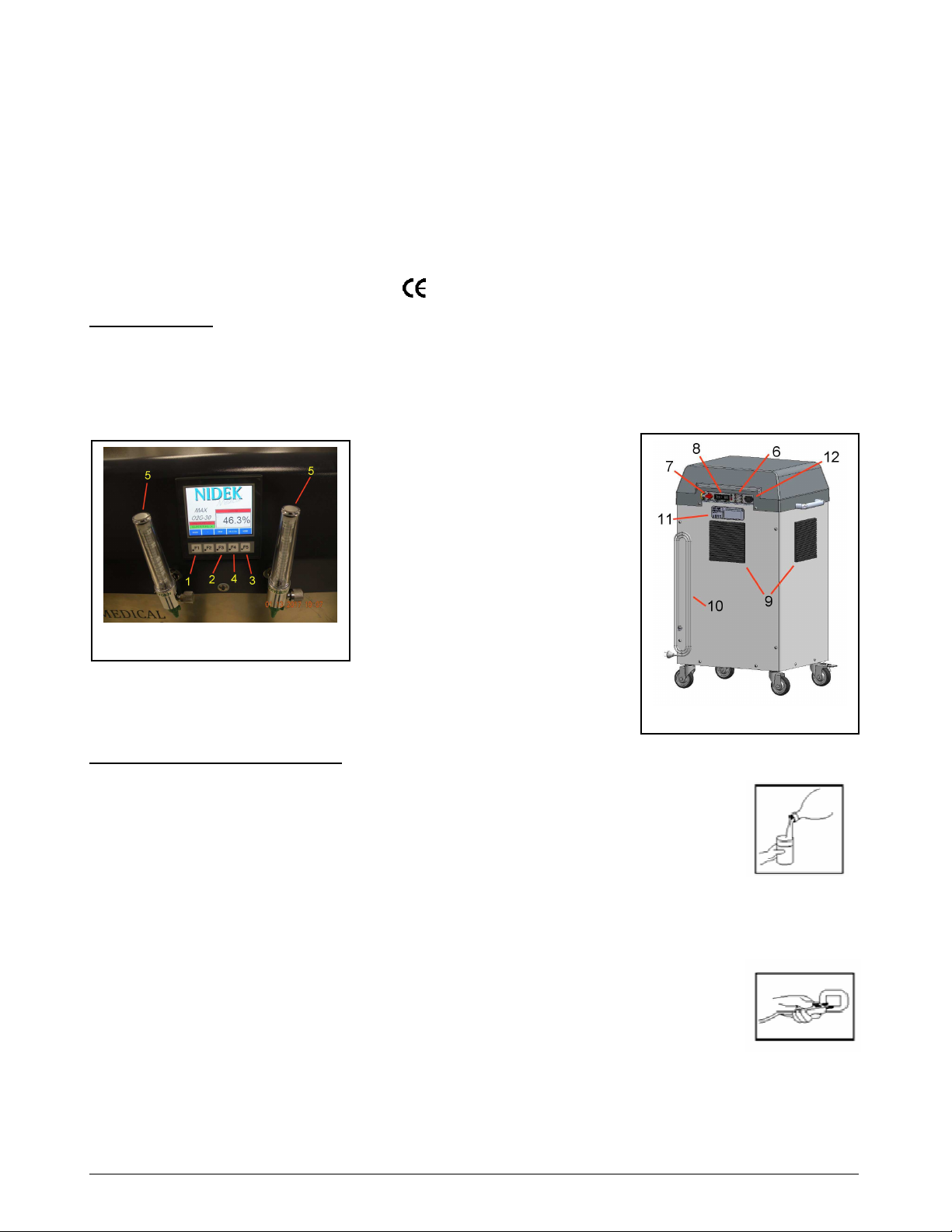
2.1 Front panel (Fig. 2.1)
1. Start Button
2. Stop Button
3. Home Button
4. Utility Button
5. Flow Meters
2.2 Rear panel (Fig. 2.2)
6. Circuit Breakers
Figure 2.1
7. Mains Switch
8. Hour Meters (x 2)
9. Cabinet Air Filter (x 3)
10. Mains Power Supply
11. Manufacturer's Technical Label
12. Alarm Battery (9V)
Figure 2.2
3. STARTING UP / INSTALLATION
3.1 Use in direct oxygen therapy
a. Ensure that the Mains Switch (Fig. 2.2–7) is in the “O” (OFF) position.
b. Connect the oxygen tube to one of the Flow Meters (Fig. 2.1-5)
• If used with a high flow humidifier bottle:
• Unscrew the flask and fill it with distilled water up to the line. Then screw the lid on
the humidifier flask until there are no leaks.
• Connect the oxygen tube to the humidifier outlet nozzle. The tube between the
cannula and the device should be limited to 20 meters (60 feet) long in order to ensure that the oxygen
flow rate remains within specification values.
• Ensure that all of the parts are connected correctly so as to avoid leaks
• Connect humidifier bottle directly to the flow meter.
c. Plug the Mains Power Supply (Fig. 2.2-10) into a power outlet of the correct voltage and
frequency as defined on the manufacturer's technical label (Fig. 2.2-11).
d. Turn the Mains Switch (Fig. 2.2-7) to the “I” (ON) position. Press the START button (Fig. 2.1-
1) on the front of the display panel. The panel displays will remain red until the oxygen
concentration exceeds the set point. Once the set point is reached, the displays will turn green
and indicate the concentration on the display panel. (See section 5.5 Indicators for further information)
Note: the required oxygen concentration is normally obtained within five minutes after the unit is started.
e. Adjust the Flow Meter (Fig. 2.1-5) to the prescribed value.
Note: View the Flow Meter from straight on for accurate settings.
______________________________________________________________________________________________________________
2010-9801CE-C October 2017 Page 3 of 12
Page 4

f. Check that the oxygen flows out of the administration device (nasal cannulas or other) by placing
the orifice(s) on the surface of a glass of water. The flow should disturb the surface of the water.
g. Adjust the nasal cannula to suit your face.
h. At the end of the treatment, press the Stop Button (Fig. 2.1-2) to shut the device down. If the
device will not be restarted, then place the Mains Switch (Fig. 2.2-7) in the “O” (OFF) position to
shut the device down. The oxygen enriched air flow continues for approximately one minute after
the device is stopped.
Note: After turning the unit off, the user must wait 5-10 minutes before turning it back on. System pressure
must dissipate before the unit will properly restart.
4. CLEANING - MAINTENANCE
4.1 Cleaning
Only the outside of the device is to be cleaned, with a soft, dry cloth or, if necessary, a damp sponge, then thoroughly dried
with wipes and an alcohol based solution. Acetone, solvents or any other inflammable products must not be used. Do not
use abrasive powders.
The removable cabinet air filters (Fig. 2.2-9) are located on each side and on the back of the machine. Each must be cleaned
in warm water and household detergent weekly or after approximately 100 hours of use. More frequent cleaning is
recommended in dusty environments. Dry before reinstalling.
4.2. Daily disinfection
Because there is a final product filter inside the device, daily disinfection concerns only the external oxygen therapy
accessories: humidifier bottles and nasal cannulas (refer to the respective instructions for use).
The device must be switched off when alcohol based solutions are used.
a. The following minimum guidelines must be observed:
Humidifier: (If prescribed by a physician)
Clean according to the manufacturer's instructions. If no instructions are provided, do the following:
Daily:
• Empty the water from the humidifier.
• Rinse the humidifier flask under running water.
• Fill humidifier up to the mark with distilled water.
Regularly:
• Disinfect the humidifier parts by immersing them in a disinfectant solution (In general, we recommend using a
solution of 1 part vinegar diluted with 10 parts water).
• Rinse and dry.
• Check that the humidifier lid seal is in good condition.
Oxygen tubing and nasal cannula: Follow the manufacturer’s instructions.
b. For each new patient:
Follow the instructions from the humidifier manufacturer. The device must be cleaned and disinfected as per the above
instructions. The cabinet air filters (Fig. 2.2-9) should be washed or replaced. The entire oxygen administration circuit
(oxygen therapy nasal cannulas, etc.) must be changed.
4.3 Maintenance
No special maintenance needs to be carried out by the patient. Your equipment supplier performs periodic maintenance
operations to assure continued reliable service from the device.
5. USEFUL INFORMATION
5.1 Accessories and spare parts
The accessories used with the device must:
• be oxygen compatible,
• be biocompatible,
• Comply with the general requirements of the FDA Quality System Regulation or the 93/42/EEC European
Directive as appropriate.
The connectors, tubes, nasal cannulas, or masks must be designed for oxygen therapy usage.
The accessories with a Nidek Medical part number reference, or included in the set of accessories supplied with the device,
comply with these requirements. Contact your equipment supplier to obtain these accessories.
______________________________________________________________________________________________________________
2010-9801CE-C October 2017 Page 4 of 12
Page 5

Note: The use of certain administration accessories which are not specified for use with this concentrator may reduce its
performance and void the manufacturer’s responsibility (ISO 8359).
AVAILABLE ACCESSORIES IF PRESCRIBED BY A PHYSICIAN
• Humidifier: Part Ref. 9251-8774 (6-15LPM)
• Cannula with 2 m (7 ft.) tubing: Part Ref. 9251-8780 (up to 15LPM)
• Extension Tubing 7.7 m (25ft): Part Ref. 9012-8781
• Tubing Adapter: Part Ref. 9012-8783
• Flow Meter (0-15lpm) Part Ref. 9800-1047
The items listed above are available from Nidek Medical Products, Inc.
5.2 Materials in direct or indirect contact with the patient
• Concentrator enclosure/handles Aluminum / Kydex
• Mains power supply PVC
• Cabinet air filters Polyester
• Mains Switch/Power Cord Nylon/PVC
• Casters Polyurethane
• Oxygen outlet/Cabinet Screws Stainless Steel/Brass
• Printed labels Polycarbonate
• Pipe/Tubing Aluminum, PVC, polyurethane and/or silicone
• Humidifier Polypropylene
• Inlet Filters Polypropylene
5.3 Operating principles
The compressor sends filtered ambient air to an electronic valving system, which allows compressed air to pass to the
column in production. The columns contain a molecular sieve, whose function is to adsorb the nitrogen and thus allow
oxygen to pass. During this process, the column which is being "regenerated" is connected to the ambient air and flow of
oxygen enriched product is passed through it (from the column "in production"). In this way, when one column is in
production, the other is in a nitrogen desorption or "regeneration" phase. The oxygen enriched product then passes through
a bacterial filter located prior to the booster pump. The oxygen enriched product finally passes thru a booster pump to
increase the pressure to 50psi (3.4bar) and out to the oxygen discharge fitting.
5.4 Alarms - Safety devices
5.4.1 Alarms
• No voltage detection: In the event of a loss of mains power, a continuous audible alarm is activated. The alarm
can be tested by actuating the Mains Switch (Fig 2.2-7) when the mains power supply is not plugged into the wall
receptacle. Periodically check to alarm to make sure the 9V alarm battery is OK.
• Oxygen concentration: The oxygen monitor measures the concentration and activates an audible and visual
alarm if it falls below the alarm set point percentage. (See section 5.5 Indicators for more information on visual
alarm)
• Maintenance of the device alarms: No special maintenance is required. The alarm set point is factory set and the
setting cannot be adjusted. All OCSI models are set at 87% ± 3%. The equipment supplier checks that the device is
still operating correctly when the routine checks are performed on the device.
5.4.2 Safety devices
Compressor motors (x 4):
• Thermal safety is ensured by a thermal switch situated in the stator winding (145 ± 5° C).
Electrical protection of the device:
• A 15A circuit breaker (Fig. 2.2-6) is incorporated into the back cabinet of all models. There are also 5 additional
5A circuit breakers for each of the compressors and the control board.
• Class I device protection (EN60601-1 standard)
Safety valve:
• The device is fitted on the low pressure compressor outlet and is calibrated to 3.4 bar (50 psig). It is also fitted with
a safety valve on the high pressure compressor outlet that is calibrated to 7.0 bar (115 psig).
______________________________________________________________________________________________________________
2010-9801CE-C October 2017 Page 5 of 12
Page 6

Fig 5.5.2
- Panel Display (Utilit
y Screen)
5.5 Indicators
Fig 5.5.1 - Panel Display (Home Screen)
Oxygen Concentration Status Indicator
The Oxygen Concentration Status Indicator is an electronic module capable of checking the effective oxygen
concentration supplied by the concentrator. The oxygen monitor measures the concentration and activates an audible
and visual alarm if it falls below the alarm set point percentage. When the device is started, the display located on the
front panel will show the oxygen concentration percentage. It should take approximately 5 minutes for the percentage
to reach the set point. Once this happens, the heading bar will turn green and your device is ready to use.
5.5.1 Green Headings
The display panel will show the oxygen concentration and pressure headings in red until the set points are reached.
When all headings are green, the device is ready to provide oxygen enriched air to the patient.
5.5.2 Red Headings
The HOME and PROCESS screens will show red headings if something is operating outside of normal conditions.
The HOME screen shows the following: outlet pressure low, concentration low, and temperature high. The PROCESS
screen shows the following: low pressure permissive, low pressure acceptable, low pressure above minimum, high
pressure demand, high pressure OK, low oxygen concentration and high temperature. Please see section 5.10 of this
guide for troubleshooting your device.
5.6 Expected Service Life
The expected service life of this device is 10 years, with proper maintenance.
5.7 Technical characteristics
Physical Properties
• Dimensions: L x W x H: 530 x 610 x 1120 mm (21 x 24 x 44 in.)
• Caster diameter: 100 mm (4.0 in.)
• Tilt angle (transport with humidifier fitted): 70°
• Weight: 113 kg / 250 lbs
• Noise level within ISO 80601-2-69:2014 guidelines
______________________________________________________________________________________________________________
2010-9801CE-C October 2017 Page 6 of 12
Flow values:
• Continuously Adjustable Variable Area Flow-meter, up to two outlets: 1 to 15 lpm each
Accuracy of flow supplied:
• In compliance with the ISO 60601-2-69:2014 standard, the flow supplied is equal to the flow set on the flowmeter,
accurate to within ± 10% or 200 ml/min, whichever is the larger of the two.
Average oxygen content:
• 2 lpm: > 90% (Values at 21°C and at one atmosphere pressure)
• 30 lpm: from 87% to 95.5% (Values at 21°C and at one atmosphere pressure)
• Minimum recommended flow: 2 lpm (outlets combined)
• Maximum recommended flow: 30 lpm (outlets combined)
The variation of the maximum recommended flow does not exceed ± 10 % of the indicated value when a back
pressure of 6.9 kPa (1 psig) is applied to the output of the device. The maximum outlet pressure is: 50psig (3.4bar)
Page 7

Electrical power supply:
MAX 30lpm 230V MAX 30LPM 230V
Frequency
Model 3005 3010
Average
Power
Protection
Class
Mains
Protection
Filters:
• On both sides and back of the device: THREE cabinet air filters (Fig. 2.2-9).
• At the compressor input: THREE inlet air filters (technician only).
• Before the oxygen outlet: a final product filter < 0.3 µm. (technician only)
Air circulation:
• Multiple tubeaxial fans (x10) cool the compressor compartment and the heat exchanger coils.
Environmental limit conditions:
The performance of the device (especially the oxygen concentration) are quoted at 21°C (70°F) and one atmosphere.
Performance may change with temperature and altitude.
• The device must be stored, transported and used in the vertical position only.
• Ambient temperature of between 10°C and 40°C (50ºF to 105°F) operation.
• Storage temperature from -20°C to 60°C (0°F to 140°F).
• Relative humidity of between 15 % and 95 % operation and storage, both non-condensing.
• Altitude (21°C): Up to 1500m (5000ft) without degradation;
Consult your equipment provider for further information regarding 1500 m to 4000m (5000 to 13000ft).
Complies with EN60529-1:2001 IPX1 rating; spilling of a glass of water.
50Hz 60Hz
2100 Watts 2000 Watts
Class I Class I
15A 15A
5.8 Standards – Max 30
ISO 80601-2-69:2014 Oxygen concentrators for medical use.
EN60601-1[UL60601-1:2005 Medical Device Electrical Safety]
CAN/CSA-C22.2No.601.1-M90 w/A1&A2: Electrical Safety- Medical Devices.
EN60601-1-2:2014 Electromagnetic Compatibility
Max 30 Serial No. __________________________
Date first used: __________________________
Maintained by: __________________________
Your equipment provider address: ________________________
Telephone: ______________________
5.9 Preventative Maintenance:
a. Wash THREE cabinet air filters (Fig. 2.2-9) weekly.
b. Inspect THREE inlet air filters during each service. Replace filters annually, or more often depending on environment.
c. Check oxygen concentration every 15,000 hours or 3 years to verify the continuing OCSI function.
d. Periodically check the 9V battery to ensure the proper operation of the power loss alarm.
The manufacturer’s instructions for the preventive maintenance of the devices are defined in the service manual, part ref:
2010-9800 NUVO MAX Installation and Service Manual. Check with your service provider for any updates to
recommended schedules. The work must be carried out by suitably trained technicians certified by the manufacturer. Use
original spare parts only (see section 4.3 Maintenance in this User’s Guide). Upon request, the supplier can provide circuit
diagrams, spare parts lists, technical details or any other information of use to qualified technical personnel for parts of the
device which are designated as being the manufacturer’s responsibility or by the manufacturer as repairable.
Medical Device Regulations require users and service providers to report to the manufacturer any incident that could, if
repeated, result in injury to any person.
______________________________________________________________________________________________________________
2010-9801CE-C October 2017 Page 7 of 12
Page 8

ed air flow is interrupted at the
5. 10. Troubleshooting.
Observations Possible Causes Solutions
The I-O (ON/OFF) button is in the “I” (ON)
position but the device does not operate.
The alarm test does not work.
(See Section 5.4.1 in this User’s Guide)
The I-O (ON/OFF) button is in the “I” (ON)
position, the compressor is operating and there is
a flow but the green light is not lighted.
Mains Power cable (Fig. 2.2-10)
is not correctly plugged into the
Check the cable connection.
wall outlet.
9V Battery is dead
Internal electrical fault.
Replace 9V battery and retest.
Contact your equipment supplier.
Faulty indicator. Contact your equipment supplier.
The I-O (ON/OFF) button is in the “I” (ON)
position but there is no flow. The audible alarm
sounds continuously.
The I-O (ON/OFF) button is in the “I” (ON)
position, the compressor is operating and there is
a flow but the audible alarm sounds
continuously.
Pneumatic connection broken or
other pressure problem.
Internal electrical fault.
Pneumatic circuit fault or low
purity.
Stop the device by pressing the I-O
(ON/OFF) button.
Contact your equipment supplier.
Stop the device by pressing the I-O
(ON/OFF) button.
Contact your equipment supplier.
Stop the device by pressing the I-O
The compressor stops in mid-cycle, then starts
again after a few minutes.
Compressor thermal safety
device has been activated.
Dirty Filters.
Fan is not working.
(ON/OFF) button and wait for it to cool
down.
Clean cabinet filter. Restart.
If the device does not start, contact your
equipment supplier.
The oxygen enrich
nasal cannula outlet.
The flow at the nasal cannula outlet is irregular.
Tube disconnected or humidifier
cap is not tight.
Cannula tubing is kinked or
restricted.
Check that tubing connections are secure
and that the humidifier is sealed.
Straighten the tubing; contact your
equipment supplier if damaged.
Maintenance Items
Cabinet Air Filter: Part Ref: 9600-1053; (Fig. 2.2-9) Wash weekly; Replace as needed.
Inlet Air Filter Element: Part Ref: 9800-1027; Inspect at each service visit; Replace annually.
9V Battery Part Ref: 7206-0027; Inspect at each service visit; Replace annually.
Please record all maintenance activity in the Maintenance Log found in the service manual and online at
www.nidekmedical.com under the 'Maintenance Log' tab.
______________________________________________________________________________________________________________
2010-9801CE-C October 2017 Page 8 of 12
Page 9

be connected to an uninterruptable power supply (UPS).
6. EMC, Electromagnetic Statements
______________________________________________________________________________________________________________
2010-9801CE-C October 2017 Page 9 of 12
Page 10

NOTES:
__________________________________________________________________________________
__________________________________________________________________________________
__________________________________________________________________________________
__________________________________________________________________________________
__________________________________________________________________________________
__________________________________________________________________________________
__________________________________________________________________________________
__________________________________________________________________________________
__________________________________________________________________________________
__________________________________________________________________________________
__________________________________________________________________________________
__________________________________________________________________________________
__________________________________________________________________________________
__________________________________________________________________________________
__________________________________________________________________________________
__________________________________________________________________________________
__________________________________________________________________________________
__________________________________________________________________________________
__________________________________________________________________________________
__________________________________________________________________________________
__________________________________________________________________________________
__________________________________________________________________________________
__________________________________________________________________________________
__________________________________________________________________________________
__________________________________________________________________________________
______________________________________________________________________________________________________________
2010-9801CE-C October 2017 Page 10 of 12
Page 11

NOTES:
__________________________________________________________________________________
__________________________________________________________________________________
__________________________________________________________________________________
__________________________________________________________________________________
__________________________________________________________________________________
__________________________________________________________________________________
__________________________________________________________________________________
__________________________________________________________________________________
__________________________________________________________________________________
__________________________________________________________________________________
__________________________________________________________________________________
__________________________________________________________________________________
__________________________________________________________________________________
__________________________________________________________________________________
__________________________________________________________________________________
__________________________________________________________________________________
__________________________________________________________________________________
__________________________________________________________________________________
__________________________________________________________________________________
__________________________________________________________________________________
__________________________________________________________________________________
__________________________________________________________________________________
__________________________________________________________________________________
__________________________________________________________________________________
__________________________________________________________________________________
______________________________________________________________________________________________________________
2010-9801CE-C October 2017 Page 11 of 12
Page 12

EU Representative
Nidek Medical Products, Inc.
3949 Valley East Industrial Drive
Birmingham, Alabama 35217 U.S.A.
Tel: 205-856-7200 Fax: 205-856-0533
______________________________________________________________________________________________________________
2010-9801CE-C October 2017 Page 12 of 12
mdi Europa GmbH
Langenhagener Str. 71
30855 Hannover-Langenhagen
Germany
Tel: +49-511-39-08 95 30
Fax: +49-511-39-08 95 39
info@mdi-europa.com
www.mdi-europa.com
 Loading...