

Page 1

NIDEK
GREEN LASER PHOTOCOAGULA T OR Model GYC-1000
INTEGRATED/ATTACHABLE SLIT LAMP DELIVERY UNIT
INTEGRATED WITH or ATTACHABLE TO THE NIDEK SL-1800
OPERA TOR’S MANUAL
(SUPPLEMENT TO THE GYC-1000 OPERATOR’S MANUAL)
Page 2

NIDEK CO., LTD. : 34-14, Maehama, Hiroishi-cho, Gamagori, Aichi 443-0038, Japan
(Manufacturer) Telephone: (0533) 67-6611
Facsimile: (0533) 67-6610
NIDEK CO., LTD : 6th Floor, Takahashi Bldg., No.2, 3-chome, Kanda-jinboucho
(Tokyo Office) Chiyoda-ku, Tokyo 101-0051, Japan
Telephone: (03) 3288-0571
Facsimile: (03) 3288-0570
Telex: 2226647 NIDEK J
NIDEK INCORPORATED : 47651 Westinghouse Drive, Fremont, California 94539, U. S. A.
(United States Agent) Telephone: (510) 226-5700
Facsimile: (510) 226-5750
NIDEK SOCIETE ANONYME : Europarc 13, rue Auguste Perret, 94042 CRETEIL, France
(Authorized Representative) Telephone: (01) 49 80 97 97
Facsimile: (01) 49 80 32 08
2005. 5
17102-P902B
Printed in JAPAN
Page 3
BEFORE USE OR MAINTENANCE OF THE PHOTOCOAGULATION
SYSTEM, READ THIS MANUAL AND OPERATOR’S MANUAL OF THE
MAIN BODY.
THIS OPERA TOR’S MANUAL ONLY CONTAINS INFORMA TION TO
UNDERST AND THE OPERA TING PROCEDURES AND MAINTENANCE
OF THE INTEGRA TED/ATT ACHABLE SLIT LAMP DELIVER Y UNIT
(NIDEK SL-1800).
This manual contains information to understand the photocoagulation system that is comprised
when the NIDEK GREEN LASER PHOTOCOAGULA TOR Model GYC-1000 (main body)
is connected with the INTEGRATED/ATTACHABLE SLIT LAMP DELIVERY UNIT
(NIDEK SL-1800).
This manual provides general descriptions of the photocoagulation system, cautions
for safety , specifications, accessories, operating procedures, and maintenance procedures.
As for the detailed operating procedures of the main body or other optional delivery
units, refer to the particular operator’s manual.
IEC 60601-1 is applied to the contents described in this manual. To understand how to
correctly use the photocoagulation system, this manual and the operator’s manual of the main
body are needed. Especially, cautions for safety and operating procedures should be understood
thoroughly before using the laser system. Be sure to store this manual with the main body and
refer to it whenever necessary .
Use of the photocoagulation system is limited to the treatment of eye disease by qualified
physicians only . The physicians are responsible for the application of the photocoagulation
system and the technical selection of the treatment of various eye diseases.
If you find any problems during, or have any questions about operation, please contact NIDEK
or your authorized distributor.
[Note on display of the exposure time and the interval time (in the repeat mode)]
When the exposure time or the interval time (in the repeat mode) on the display of the control box of
the GYC-1000 is less than “1.00” or “1.0”, “0” before the decimal point is displayed small. (Example:
if the setting is “0.30”, the display shows “ ”.)
Page 4

Table of Contents
§
1 INTRODUCTION .......................................................................................................1-1
1.1 Outline of the Slit Lamp Delivery Unit .........................................................................1-1
1.2 Indications for Use .....................................................................................................1-2
1.3 Classifications of the Slit Lamp Delivery Unit ...............................................................1-2
1.4 Symbol Information ....................................................................................................1-3
§
2 SAFETY ......................................................................................................................... 2-1
2.1 Storage, T ransport, and Installation Precautions...........................................................2-1
2.2 W iring and Connection Precautions .............................................................................2-2
2.3 Usage Precautions......................................................................................................2-3
2.4 After Use Precaution, Maintenance, and Checks .........................................................2-5
2.5 Disposal.....................................................................................................................2-6
2.6 Safety Devices ...........................................................................................................2-6
2.7 Nominal Ocular Hazard Distance (NOHD).................................................................2-6
2.8 Labels........................................................................................................................2-7
§
3 SYSTEM DESCRIPTION............................................................................................ 3-1
3.1 NIDEK SL-1800 Integrated Delivery Unit.................................................................. 3-1
3.2 NIDEK SL-1800 Attachable Delivery Unit.................................................................3-5
3.3 Common Accessories of the Integrated and Attachable Delivery Units .........................3-7
3.4 Options......................................................................................................................3-8
Page
§
4 INST ALLATION, STORAGE, AND TRANSPOR T .................................................. 4-1
4.1 Installation ..................................................................................................................4-1
4.1.1 Configuring the slit lamp delivery unit..................................................................4-1
4.1.2 Installing the photocoagulation system ................................................................4-4
4.1.3 Optical adjustment ............................................................................................4-9
4.2 Storing the Attachable Delivery Unit ..........................................................................4-12
4.3 Transporting the Integrated Delivery Unit...................................................................4-17
§
5 OPERA TING PROCEDURES.....................................................................................5-1
5.1 Operation Flow..........................................................................................................5-1
5.2 Starting the Photocoagulation System ..........................................................................5-2
5.3 Preparing for Laser Emission ......................................................................................5-3
5.4 Laser Emission ...........................................................................................................5-7
5.5 Indications of Misoperation....................................................................................... 5-11
5.6 Emergency Stop....................................................................................................... 5-11
Page 5

§
6 MAINTENANCE.......................................................................................................... 6-1
6.1 Replacing the Fuses....................................................................................................6-1
6.1.1 For the motorized optical table ..........................................................................6-1
6.1.2 For the slit lamp power supply ...........................................................................6-2
6.2 Replacing the Illumination Lamp ..................................................................................6-3
6.3 Replacing the Fixation Lamp .......................................................................................6-4
6.4 Indication of Failure of the Slit Lamp Power Supply ....................................................6-5
6.5 Cleaning .....................................................................................................................6-6
6.5.1 Cleaning the exterior..........................................................................................6-6
6.5.2 Cleaning the optical parts...................................................................................6-6
6.5.3 Cleaning the fiber optic cable .............................................................................6-7
§
7 SPECIFICA TIONS AND CONFIGURATION ........................................................... 7-1
7.1 Specifications .............................................................................................................7-1
7.2 Standard Configuration ...............................................................................................7-3
7.2.1 Standard configuration for the integrated delivery unit .........................................7-3
7.2.2 Standard configuration for the attachable delivery unit.........................................7-3
7.3 Options......................................................................................................................7-3
Words in This Manual..................................................................................End of this manual
Page 6
§
1
1.1 Outline of the Slit Lamp Delivery Unit
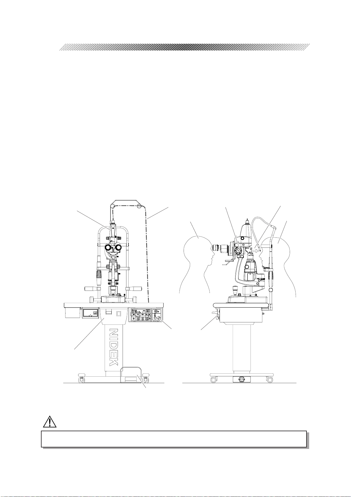
This delivery unit is connected to the NIDEK GREEN LASER PHOTOCOAGULATOR, Model
GYC-1000 (main body) to comprise the photocoagulation system and to treat affected areas
using the slit lamp, NIDEK SL-1800.
The integrated delivery unit which incorporates the SL-1800 comprises the photocoagulation system in
connection with the GYC-1000 main body .
The attachable delivery unit is mainly the photocoagulation unit and the protective filter unit. They are
attached to your slit lamp (NIDEK SL-1800) to comprise the integrated delivery unit. The comprised
integrated delivery is connected to the GYC-1000 to comprise the photocoagulation system.
This photocoagulation system allows the operator to select between photocoagulation with the green
laser beam (wavelength: 532 nm) and observation of the affected area with the slit lamp.
INTRODUCTION
Photocoagulation unit
Motorized optical table
Fiber optic cable
Operator
GYC-1000
main body
Slit lamp SL-1800
Laser emission
Patient
Foot switch
<Front view>
<Right side view>
CAUTION
• United States Federal law restricts this device to sale by or on the order of a physician.
Page 7

1.2 Indications for Use
The Nidek Green Laser Photocoagulator Model GYC-1000 Integrated/Attached Slit Lamp Delivery
Unit is intended to be used in ophthalmic surgical procedures, including retinal and macular
photocoagulation, iridotomy and trabeculoplasty .
1.3 Classifications of the Slit Lamp Delivery Unit
[Classification under the provision of 93/42/EEC (MDD)] Class IIb
As long as this delivery unit is connected to the main body , this delivery unit is classified as a
Class IIb unit.
[Class of the laser system] Class 4
As long as this delivery unit is connected to the main body , this unit is classified as a Class 4
system.
A Class 4 laser is capable of producing injuries to the eye with direct laser exposure, or by diffuse
reflections (0.5 W or more).
1 - 2
[Protection method against electric shock] Class I
As long as this delivery unit is connected to the main body , this delivery unit is classified as a
Class I system.
A Class I system is a system in which the protection against electric shock does not rely on
basic insulation only, but which includes an additional safety precaution in such a way that
means are provided for the connection of accessible conductive parts to the protective (earth)
conductor in the fixed wiring of the installation in such a way that accessible conductive parts
cannot become live in the event of a failure of the basic insulation.
[Degree of protection against electric shock] Type B applied part
As long as this delivery unit is connected to the main body , this delivery unit is classified as a
system with a Type B applied part.
A system with a Type B system provides an adequate degree of protection against electric
shock particularly regarding;
- allowable leakage currents
- reliability of the protective earth connection (if present)
[Degree of protection by the enclosure]
This delivery unit is classified as a IP20.
An IP20 system is protected against an ingress of solid foreign objects, such as a finger
having a diameter of 12.5 mm or greater . However , it is an ordinary system without protection
against an ingress of liquids. Be careful not to expose water to this delivery unit.
[Sterilization methods recommended by the manufacturer]
This delivery unit does not have any part to be sterilized or disinfected.
Page 8
1 - 3
[Degree of safety in the presence of flammable anesthetics and/or flammable cleaning agents]
This delivery unit should be used in an environment where no flammable anesthetics and/or flammable
cleaning agents are present.
[Mode of operation]
As long as this delivery unit is connected to the main body , this unit is an intermittent operating
system.
* During use of the slit lamp, care should be taken not to let the lamp house be excessively heated by
continuous use of the illumination of high intensity. As a guideline, if the illumination of the maximum
intensity is used for 10 minutes, turn off the illumination and wait for 20 minutes to cool the lamp
house.
[Classification by transportability]
This delivery unit is classified as the transportable system.
1.4 Symbol Information
This symbol indicates the master switch setting. When the switch is in this position,
the power is not supplied to the photocoagulation system.
This symbol means that the system is classified as a system with a type B applied part.
This symbol indicates that important descriptions related to operation or maintenance
are contained in the operator’s manual and that an operator must refer to the operator’s
manual prior to operation and maintenance.
Page 9
§
2
In this manual, signal words are used to designate the degree or level of safety alerting. The
definitions are as follows.
WARNING: Indicates a potentially hazardous situation which, if not avoided,
could result in death or serious injury.
CAUTION: Indicates a potentially hazardous situation which, if not avoided,
may result in minor or moderate injury or in a property damage
accident.
Even situations indicated by WARNING and CAUTION may result in serious injury
under certain conditions. Safety precautions must be strictly followed at all times.
2.1 Storage, Transport, and Installation Precautions
SAFETY
CAUTION
• In storage, transport, and installation, verify that the following conditions are met:
- Not exposed to direct sunlight or ultraviolet rays
- Not exposed to rain or water
- No chemicals or organic solvents are present
- No poisonous gas, sulfur, salt, or lar ge amount of dust is contained in the air
- Level and stable without vibration and shock
- The following are the specified environmental conditions for storage and transport (packed
condition), and installation (unpacked condition)
For storage and transport:
T emperature: 14 to 122 ºF (- 10 to 50 ºC) / Humidity: 10 to 95 % (non-condensing)
For installation:
T emperature: 50 to 86 ºF (10 to 30 ºC) / Humidity: 30 to 85 % (non-condensing)
• In transport of the photocoagulation system, observe the following instructions:
- T o avoid injury or malfunction, remove the delivery unit from the main body and store them
in the carrying case or shipping carton (keep the shipping carton used for delivery)
- T o avoid shift of the optical axis, do not subject the main body or the delivery unit of the
combination system to physical shock even if they are packed in the carrying case or shipping
carton.
- T o avoid condensation, keep the change in temperature as little as possible.
Page 10
2 - 2
CAUTION
• In installation of the photocoagulation system, observe the following instructions:
- T o avoid troubles from condensation, let the photocoagulation system sit until the condensation
has dissipated before installation.
- To avoid malfunction from change in temperature and condensation, do not install the
photocoagulation system where it is exposed to the direct flow of air conditioning.
- T o avoid adverse effect on the lens or mirror , do not install the photocoagulation system in a
high temperature, high humidity, or dusty environment.
- T o let the photocoagulation system dissipate heat properly , install it so that the air vent on the
rear panel and the wall or the foreign object are more than 10 cm apart.
• Attach or remove the delivery unit to the main body with the key switch off ( ).
If the delivery unit is attached ore removed with the key switch on ( ), an error may occur.
2.2 Wiring and Connection Precautions
CAUTION
• In handling the power cord and cables, observe the following instructions:
- T o avoid short circuit or fire from broken wire, perform the connection and disconnection
holding the plug, and do not coil the power cord and connecting cables forcefully in a short
curvature, or crush or pinch them with heavy objects.
- T o avoid short circuit or fire, replace the broken wire with a new one.
- Never pull the power cord or a connecting cable to transport the system.
• In handling the power cord, observe the following instructions:
- T o avoid malfunction or electric shock, use a grounded power outlet which meets the power
requirements specified in the label on the main body .
- T o avoid malfunction or fire, do not overload the electrical outlet.
• In handling the connecting cable of the photocoagulation system, observe the following
instructions:
- T o avoid malfunction or failure of the system, connect the cable plug to the DELIVER Y
connector on the front panel of the main body .
• In handling the fiber optic cable, observe the following instructions:
- T o avoid damage or deterioration in laser delivery performance, do not let any part of the
fiber optic cable bend with a radius of 10 cm (4.5 in) or more.
- T o avoid deterioration in laser delivery performance, be careful not to soil or damage the tip
of the plug of the fiber optic cable plug, especially when inserting the plug into the FIBER
connector.
- Connect the cable plug to the FIBER connector on the front panel of the main body .
Page 11

2.3 Usage Precautions
WARNING
• Use of controls or adjustments, or performance of procedures other than those specified herein
may result in hazardous radiation exposure.
• In handling of the delivery unit, observe the following instructions:
- Only service technicians properly trained by Nidek may install and configure the
photocoagulation system. Only qualified physicians may perform emission of the green laser
for treatment.
- T o avoid hazardous radiation exposure, do not perform operation which is not described or
different from the procedure specified in the operator’s manual.
- T o avoid electric shock, do not modify nor touch the internal structure.
- T o maintain the performance of laser emission, never soil or scratch the lens or mirror .
• Before starting the photocoagulation system, observe the following instructions:
- T o avoid ignition or explosion from the laser emission, verify that there is no flammable
anesthetic gas in the operating room.
- T o protect the eyes of personnel in the operating room, instruct them to wear recommended
safety goggles (or the equivalent) before the operation and not to look at the laser beam
directly during the operation.
Recommended goggles ......Model YL-300 for frequency doubled Nd: Y AG: D315-532
L8 YL DIN
(Produced by YAMAMOTO KOGAKU CO., L TD. Japan)
- To prevent accidents, perform the check following 5.3 Checks Before Use and 5.4
Function Checks (p. 5-3) in the operator’s manual of the main body and record each
result in the list (p. 5-5) when starting operation of the photocoagulation system.
2 - 3
• During operation of the photocoagulation system, observe the following instructions:
- T o avoid unintended exposure to the laser beam, do not gaze at the aiming beam that is
emitted from the laser aperture or direct it toward personnel. Always pay attention to the
direction in which it is emitted.
- T o avoid accident caused by unauthorized personnel, do not leave the photocoagulation
system unattended while it is operational. If the operator has to be away from the system,
turn the key switch to the off position, remove the key , and store it in the customary place.
• During operation of the photocoagulation system, observe the following instructions:
- Do not use the photocoagulation system simultaneously with other electronic equipment to
avoid electromagnetic interference with the action of the system
- Do not use the photocoagulation system simultaneously in the same room with other equipment
such as a life-support equipment that has serious effects on the life of patient and the treatment,
or other measurement or treatment equipment that involves small signal.
- Do not use cables and accessories that are not specified for the photocoagulation system
because that may deteriorate the electromagnetic compatibility .
- Do not use the photocoagulation system simultaneously with portable radio frequency
communication systems because it may have an adverse effect on the system.
Page 12
2 - 4
CAUTION
• In use of the slit lamp, observe the following instructions:
- T o avoid damage to the retina of the patient, only trained physician may perform observation
using the slit lamp. Do not emit unnecessarily intense laser beam.
- T o avoid the blue hazard, set the illumination for observation to the minimum level initially ,
and then increase it until the desired intensity can be obtained. After the observation, lower
the illumination intensity to the minimum level again.
- W ipe the forehead rest, the chinrest, and the grips of the slit lamp every time before observing
a patient to keep them clean.
• For laser emission, observe the following instructions:
- When the green laser beam (wavelength: 532 nm) of the GYC-1000 is emitted into tissue,
following symptoms may occur. Pay attention to the direction of the aiming beam to avoid
emitting the laser beam into the eye or onto skin inadvertently .
- Skin symptoms........... Damage to the cornea, etc. or blindness
- Eye symptoms............ Pain or burn
- T o avoid exposure to the reflected laser beam, verify that there is no reflective object in the
optical path before laser emission.
- T o avoid excessive reaction, set the laser to a low output power initially , and then increase it
until the desired effect can be obtained. Always set the output power to the minimum after
the laser emission.
- To avoid damage to the cornea or the crystalline lens, if the indirect lens is used for laser
emission, take the magnification into consideration and take care not to make the spot size
larger than approximately 200 µm.
- T o avoid exposure to the accidentally emitted laser beam, always place the photocoagulation
system in the condition in which the laser cannot be emitted (standby mode) except when
emitting the laser.
- Confirm that the photocoagulation system is in a proper condition for laser emission by the
following procedures: (if any abnormality is found in step 2, ask Nidek for check and
adjustment.
1. Project the aiming spot on an even surface
that is not specular.
2. V erify that the intensity of the illumination
spot is even around the center as shown in
the figure on the right and that lowering of
the intensity or vignetting does not occur.
• When the green laser beam is emitted in photocoagulation using the slit lamp, the color of the
green laser beam can be seen slightly in the view field occasionally .
This occurs when the beam that is reflected from the contact lens enters the optical system for
observation. The symptom differs according to the type of contact lens, and condition in which
the green laser beam enters the contact lens.
The light intensity is attenuated to a safe level by the protective filter that is incorporated in the slit
lamp.
If an intense light is seen, stop the use of the system immediately , and ask NIDEK for checking
of the system.
Page 13

2.4 After Use Precaution, Maintenance, and Checks
CAUTION
• After use of the photocoagulation system, observe the following instructions:
- T o avoid the tracking phenomenon, if the system will not be used for a long period of time,
disconnect the power cord from the grounded power outlet.
- T o maintain the performance of laser emission, when the photocoagulation system is not
being used, turn off the power and put dust cover over it.
• For maintenance of the photocoagulation system, observe the following instructions:
- T o avoid accidents caused by improper repair of the system, only service technicians properly
trained by NIDEK may repair the system.
- T o maintain the performance of laser emission, take care not to scratch or accumulate dust
on the optical parts such as lens and mirror.
- To protect the exterior or maintain the operability of the system, do not use organic or
abrasive solvents for cleaning.
2 - 5
• For check of the photocoagulation system, observe the following instructions:
- T o maintain the performance of laser emission, ask NIDEK or your authorized distributor
for calibration of output power and exposure time of the laser beam, and for measurement
of the earth resistance and leakage current once a year .
- T o avoid infection, wipe the surface of the delivery unit (especially the inside parts of the
headband and overband) with a clean cloth dampened with alcohol before returning it to
NIDEK for repair or maintenance.
• In replacing the illumination lamp of the slit lamp, observe the following instructions:
- T o avoid burn, replace the burned-out illumination lamp when it has been cooled enough.
- T o avoid troubles, use the illumination lamp of the specified rating.
- T o avoid reduction of life time of the lamp, do not touch the glass part of it with bare hands.
If the glass part is touched with bare hands, wipe the part with a clean cloth dampened with
alcohol.
Page 14
2 - 6
2.5 Disposal
CAUTION
• When disposing of the delivery unit, follow the local governing ordinances and recycling plans.
(For details, ask NIDEK or your authorized distributor .)
• When disposing of packing materials, sort them by material and follow local governing ordinances
and recycling plans.
• When disposing of the GYC main body and the Slit lamp, see the operator’s manual for each.
2.6 Safety Devices
[LASER EMISSION indicator]
During the photocoagulation system operation (while the key switch is in the ON ( ) position), the
LASER EMISSION indicator on the slit lamp delivery unit lights up to call the operator’s attention.
[Protective filter]
T o protect the operator’ s eye from the reflected light of the green laser beam, “electrically powered”
protective filter is available.
If the filter is not set in the observation optical path when the foot switch is pressed to emit the green
laser beam, “Err2” indication appears on the control box.
[Manual reset function]
After the photocoagulation system is stopped due to the stop signal from the remote connector, the
line power being cut, or an unintended cause, etc., the system does not restart automatically even
when all the problems are solved and the system is ready to be restarted. It depends on the
operator’s decision whether to restart the system or not. T o restart the system, turn the key switch
to the OFF ( ) position (manual reset), and then to the ON ( ) position again.
2.7 Nominal Ocular Hazard Distance (NOHD)
The nominal ocular hazard distance (NOHD) of the laser beam of the slit lamp delivery unit is as
follows:
NOHD = 14.6 m
Page 15
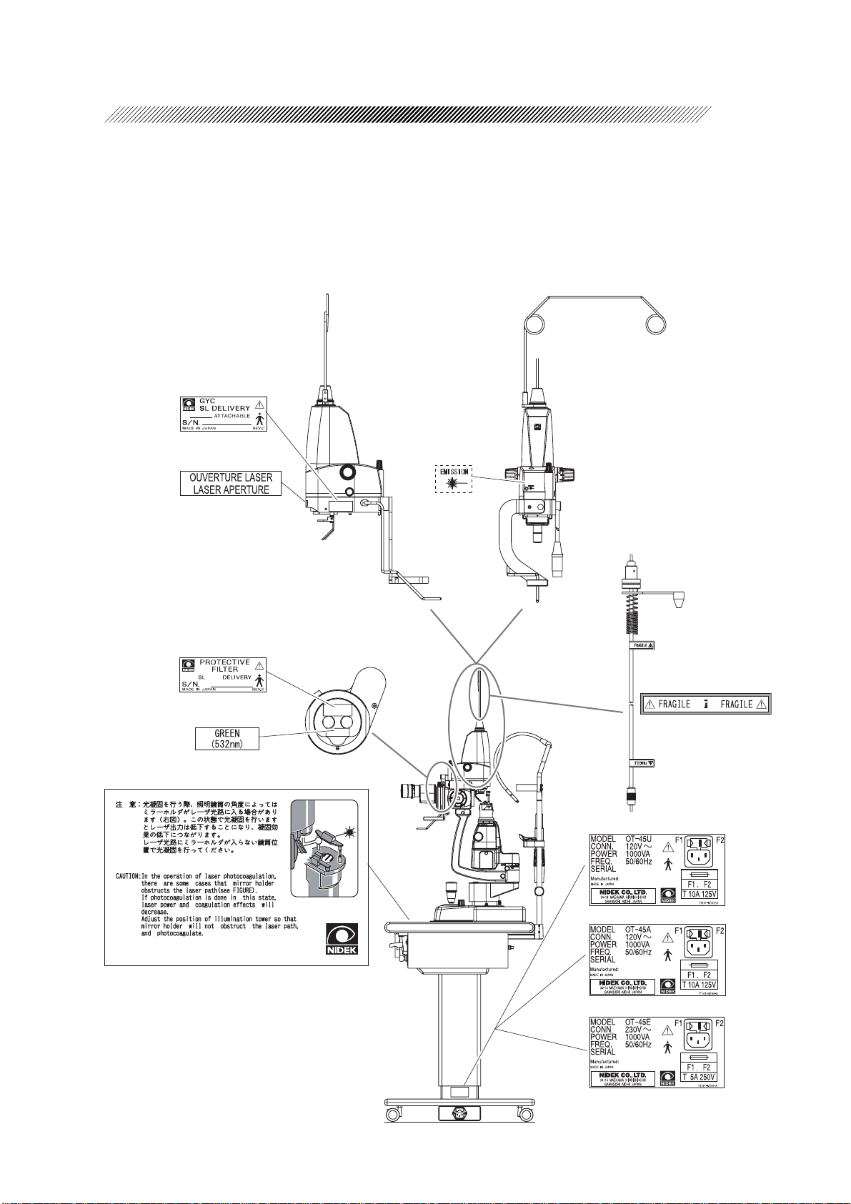
2.8 Labels
In order to call the operator’s attention, the appropriate warning labels are attached to the specified
locations on the slit lamp delivery unit.
2 - 7
This label is not attached to
the product for the US market.
[For the US market]
[For 100V area]
[For the French market and 200V area]
Page 16
§
3
3.1 NIDEK SL-1800 Integrated Delivery Unit
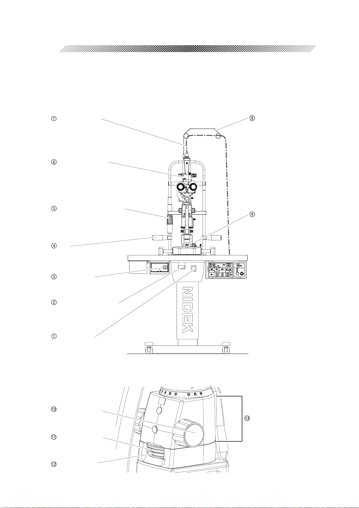
[SL-1800 Integrated Delivery Unit: Physician’s side]
SYSTEM DESCRIPTION
Fiber optic cable
Emission indicator
Chinrest elevation control
Grip
Power switch
Fiber optic cable guide
Illumination control
UP and DOWN lever for
motorized optical table
Master switch
[SL-1800 Integrated Delivery Unit: Slit/filter operation part]
Slit width control
Slit length control
Filter selector
Slit rotation control
Page 17
3 - 2
Master switch
Used to turn on or off the power of the slit lamp
and motorized optical table.
UP and DOWN lever for motorized
optical table
Used to move the motorized optical table up
and down.
When the lever is raised, the table moves up.
When it is lowered, the table moves down.
Power switch
Used to turn on or off the power of the slit lamp.
When it is turned on, the switch lights up.
Grip
Have the patient hold the grips to keep him/her
in a stable posture.
Chinrest elevation control
Used to adjust the vertical position of the patient’s
chin.
Emission indicator
Lights when the key switch of the main body is
turned to the on ( ) position.
Fiber optic cable
Delivers the laser beam from the main body to
the delivery unit. Its plug is connected to the FIBER connector on the main body .
* Handle the fiber optic cable with care because
optical fiber runs inside it.
Fiber optic cable guide
Lightens the load of the fiber optic cable on itself
when it runs from the main body to the slit lamp
delivery unit.
Illumination control
Used to adjust the intensity of the illumination
light of the slit lamp. It can be changed continuously .
Slit width control
Used to adjust the slit width. The slit width can
be changed continuously in the range from 0 to
16 mm.
Slit length control
The upper ring is the slit length control. Turning
this ring changes the slit length to 0.4, 6.5, 10.5,
16, or continuously in the range from 2 to 14
mm.
Filter selector
The lower ring is the filter selector. The following
filters can be selected by turning this ring.
[Index] [Filter] [Purpose]
Blue Blue
Green Red-free Red-free
Red Heat absorb Heat absorb
White Free aperture -------
Fluorescence and
color exciter
Slit rotation control
The part indicated with the bracket in the figure
on the left page moves 90º to left and right each.
Moving it rotates the slit up to 90º in the horizontal direction from the vertical direction.
It clicks when the slit becomes vertical.
Page 18
3 - 3
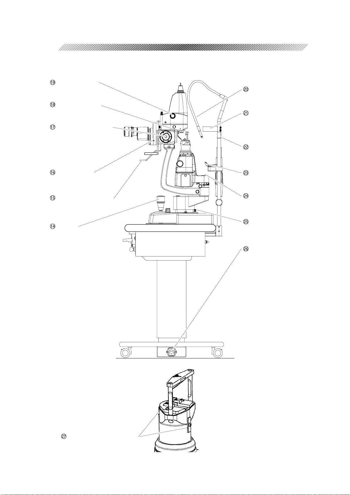
[Side view]
Spot size control
Connecting cable
Magnification changer
Fixation lamp
Forehead rest
Eye level marker
Protective filter
Micromanipulator lever
Joystick
Chinrest
Hole for mounting the
focusing rod
Base fixing knob
Fuse holder
Illumination focusing plates
Page 19

3 - 4
Joystick
Used to move the slit lamp.
The slit lamp moves up and down by rotating the
joystick. The slit lamp moves horizontally by sliding it side to side or back and forth. In addition,
the horizontal fine movement of the slit lamp can
be performed by tilting it.
Micromanipulator lever
Used for fine positioning of the aiming beam spot
and green laser beam. When this lever is released,
the spot is returned to the center of the visual
field.
Protective filter
Used to protect the operator’s eye against a reflected laser beam from a target tissue.
Magnification changer
Used to change the magnification of the microscope.
[Magnification] [Actual visual field]
32× φ 7.5 mm
20× φ 11.5 mm
12.5× φ 18.4 mm
8× φ 29.5 mm
5× φ 46.0 mm
Connecting cable
Its connector is connected to the DELIVERY
connector on the connector panel of the main
body .
Spot size control
Used to adjust the spot size of the laser beam in
the range between 50 and 990 µm.
The spot size is indicated on the control box of
the main body .
Fixation lamp
Used to fix the patient’ s visual axis by adjusting
its arm.
Forehead rest
Patient’ s forehead rests on this forehead rest.
Eye level marker
The patient’s eyes are aligned to this height.
Chinrest
Patient’s chin is placed on this.
Hole for mounting the focusing rod
Remove the cap and insert the end of the focusing rod. If the focusing rod is not used, cover the
hole with the cap.
Base fixing knob
Used to fix the horizontal movement of the slit
lamp by tightening this.
Fuse holder
The holder to set the fuses of the motorized optical table.
Fuse rating: <100V area> 250 VAC, T 6A
<200V area> 250VAC, T 3.15A
* As for the replacement of fuses, see [6.2.1
For the motorized optical table] (p. 6-2).
Illumination focusing plates
Used to adjust the focus of the illumination light.
Loosen the screws on the plates and move the
plates vertically for the adjustment. When the
proper focus is achieved, tighten the screws.
Page 20
3 - 5
3.2 NIDEK SL-1800 Attachable Delivery Unit
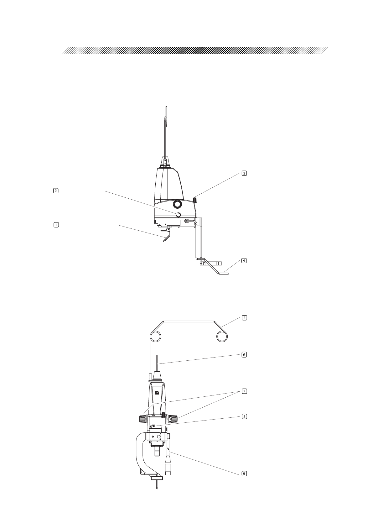
[SL-1800 Integrated Delivery Unit: Photocoagulation Unit]
<Photocoagulation unit - left side>
Retaining knob
Filter connector
Laser reflective mirror
[SL-1800 Integrated Delivery Unit: Slit/filter operation part]
<Photocoagulation unit - Physician’s side>
Micromanipulator lever
Fiber optic cable guide
Fiber optic cable
Spot size control
Emission indicator
Connecting cable
Page 21

3 - 6
Laser reflective mirror
Delivers the aiming and green laser beams into
the eye.
* Do not soil, scratch, or let dust accumulate on
the mirror..
Filter connector
Used to connect the plug of the protective filter
to the connector .
Retaining knob
Used to retain the photocoagulation unit on the
slit lamp.
Micromanipulator lever
Used for fine positioning of the aiming beam spot
and green laser beam. When this lever is released,
the spot is returned to the center of the visual
field.
Emission indicator
Lights when the key switch of the main body is
turned to the on ( ) position.
Connecting cable
Its connector is connected to the DELIVERY
connector on the connector panel of the main
body.
Fiber optic cable guide
Lightens the load of the fiber optic cable on itself
when it runs from the main body to the slit lamp
delivery unit.
Fiber optic cable
Delivers the laser beam from the main body to
the delivery unit. Its plug is connected to the FIBER connector on the main body .
* Handle the fiber optic cable with care because
optical fiber runs inside it.
Spot size control
Used to adjust the spot size of the laser beam in
the range between 50 and 990 µm.
The spot size is indicated on the control box of
the main body .
Page 22

3 - 7
[SL-1800 Attachable Delivery Unit: Protective filter unit]
Connecting cord
The connecting cord is used for driving the protective filter and detecting whether the protective filter unit is inserted into the observation path or not. The plug is connected to the filter connector on the delivery unit.
3.3
Common Accessories of the Integrated and Attachable Delivery Units
[Arm rest]
[Head belt]
Arm rest
Operator’s arm is rested on it so that position adjustment of the contact or aspheric lens is easier.
The height can be adjusted by changing the combination of the pieces.
Head belt
Used to fix the patient’s head to the forehead rest of
the slit lamp.
Page 23

3.4 Options
3 - 8
Carrying case
When the attachable delivery unit is transported
or not used for a long period of time, store it in
this case.
Safety goggles
During the combination system operation, all
personnel except the operator and patient must
wear these goggles.
Page 24

§
4
4.1 Installation
4.1.1 Configuring the slit lamp delivery unit
The following is the method of configuring the slit lamp delivery unit by attaching the attachable slit lamp
delivery unit to your slit lamp NIDEK SL-1800.
1. Attach the protective filter unit to the slit lamp.
1) Move the slit lamp delivery unit fully to the operator’s side and the microscope and illumination
arms to different directions.
2) Loosen the fixing screw A to take off the
INSTALLATION, STORAGE, AND TRANSPORT
binocular tube from the slit lamp.
3) Insert the convex mount of the protective filter
unit into the concave mount of the slit lamp,
and tighten the fixing screw A of the slit lamp.
Fixing screw A
Fixing screw B
4) Insert the mount of the binocular tube into the
concave mount of the protective filter unit, and
tighten the fixing screw B of the protective filter
unit.
2. Mount the photocoagulation unit on top of the slit lamp.
CAUTION
• When mounting the photocoagulation unit, take care not to damage the laser reflective mirror.
The performance of the laser may deteriorate.
1) While holding the photocoagulation unit, loosen
the retaining knob. Then remove the protective
cover of the laser reflective mirror.
Protective filter unit
Retaining knob
Protective cover
Page 25

2) Insert the guide pins of the photocoagulation
unit into the guide holes of the slit lamp, and
Photocoagulation unit
tighten the retaining knob to fix the
photocoagulation unit to the slit lamp.
Guide holes
Guide pin
Hole for retention
Retaining knob
3) Coil the connecting cable and fiber optic cable and place them on the optical table.
4) Connect the connecting cord of the protective
filter unit to the FILTER connector of the
photocoagulation unit.
Filter connector
Connecting cord
4 - 2
Page 26

4 - 3
3. Attach the fiber optic cable and the fiber optic cable guide to the photocoagulation unit.
CAUTION
• Pay attention to the following points when
handling the fiber optic cable:
1. Do not coil it with a radius of under 10
cm (4.5 in).
2. Do not soil or scratch the tip of the plug.
1) Loosen and remove the guide ring from the
photocoagulation unit. Attach the fiber optic
cable guide to the removed guide ring and fix it
with screws.
2) Run the fiber optic cable through the loops of
the fiber optic cable guide and guide ring.
3) Hold the fiber optic cable guide and the guide
ring with a hand. Remove the protective cap
on the plug of the fiber optic cable and screw
the plug into the top of the photocoagulation
unit with the other hand.
10 cm or more
Do not soil or
scratch here.
Fiber optic cable guide
Fix with screws
Fiber optic cable
Plug
Guide ring
4) Hold the root of the fiber optic cable guide with
a hand. Screw the guide ring into the
photocoagulation unit with the other hand.
* Match the key of the plug and the notch on the
connector.
* Turn both the plug and the guide ring clock-
wise.
4. Place the arm rest on the motorized optical table of the slit lamp.
5. Attach the head belt on the root of the forehead rest of the slit lamp.
Page 27

4.1.2 Installing the photocoagulation system
1. V erify the power supply of the main body and the slit lamp delivery unit.
V erify that the power outlet meets the power requirements labeled on the GYC main body .
CAUTION
• If the power outlet does not meet the power requirements, the combination system may be
damaged, or it may not perform properly .
2. Place the GYC main body in a place near the slit lamp for convenient use.
1) Select a method of installing the main body from the three methods described below according to
the type of the delivery unit.
4 - 4
CAUTION
• If a cart or table extension is prepared, confirm that it is level and stable before placing the
main body on them.
The main body may fall.
• Leave a clearance of 10 cm or more for the rear surface of the GYC main body.
Otherwise, air infusion for cooling down of the laser cannot be properly performed and
damage of the device may result.
• When installing the GYC main body , never pull the cables or crush them with the casters.
Physical shock to cables may cause a malfunction of the combination system.
[A: When using the box under the top board of the motorized optical table]
(For the integrated delivery unit)
Hold the right and left sides of the main body
with both hands. Then store it in the box from
the rear panel.
* Remove all the cords and cables from the main
body before storing it.
Box
GYC-1000
Main body
Page 28

4 - 5
[A: When using a cart] (For the attachable delivery unit)
Prepare a cart which has enough space for the GYC main body (approximately W: 30cm × D:
40cm).
[B: When using the table extension (option)] (For the attachable delivery unit)
Attach the table extension to the motorized optical
table.
Loosen the screws (3 pcs.) so that the fixing part
of the table extension can hold the edge of the
motorized optical table.
Securely fit the fixing part to the motorized optical
table until it comes in contact with the edge of
the motorized optical table. Then tighten the
screws (3 pcs.).
Lightly put pressure on the table extension with
your hands to verify that the main body can be
placed on it safely .
Place the main body on the table extension.
Screws
Motorized optical table of the Slit lamp
Table extension
2) Set the motorized optical table or the cart near the power outlet verified in step 1. Then lock the
caster as necessary .
Page 29

3. Connect the plugs to the GYC main body.
CAUTION
• Securely connect each plug to the specified inlet or connector .
If the plug is connected to a wrong connector or connected improperly , system malfunction
or damage to the system may result.
• Attach the delivery unit to or remove it from the main body with the key switch off ( ).
With the key switch on ( ), an error may occur .
Fiber optic cable plug
4 - 6
Slit lamp delivery
unit cable plug
Power cord
Foot switch Short plug
1) Connect the female plug of the power cord to the inlet of the main body .
2) Place the foot switch in an appropriate position and connect the cable plug of the foot switch to the
FOOT SW connector .
3) Connect the short plug (or the remote switch) to the REMOTE connector .
4) Connect the connecting cable plug of the slit lamp delivery unit to the DELIVERY connector.
5) Remove the rubber cap from the plug of the
fiber optic cable, and connect the plug to the
FIBER connector.
Rubber cap
CAUTION
• Pay attention to the following points when
handling the fiber optic cable:
1. Do not coil it with a radius of under 10
cm (4 in).
2. Do not soil or scratch the tip of the plug.
10 cm or more
Do not soil or scratch here.
4. Connect the plugs of the power cords of the main body and the motorized optical table to the
power outlets verified in step 1 (p.4-4).
Page 30

4 - 7
5. Release each fixed part of the slit lamp.
Release each fixed part illustrated in the figure on
the right.
Illumination tower
fixing knob
Microscope arm
fixing knob
Base fixing knob
6. Place the control box on a convenient place.
Remove the control box from the front panel of the main body . Place it on the motorized optical table
so that it is convenient for use and does not fall.
7. T urn on the power of the photocoagulation system.
1) Turn on ( | ) the master switches of both the main body and motorized optical table.
2) Turn on the illumination switch of the slit lamp.
Illumination switch
Master switch
8. Start operation of the photocoagulation system.
STANDBY
Turn the key switch of the main body to the on
(
) position.
The photocoagulation system enters the
ST ANDBY mode in approximately 20 seconds.
Master switch
Key switch
Page 31

9. Perform the check of the photocoagulation system.
Perform the check referring to 5.4 Function Check (p. 5-3) and record each result in the 5.5 Function
check list (p. 5-5) in the Operator’s Manual for the main body .
10. If necessary , adjust the focus of the slit lamp delivery unit.
If the focus of the laser spot is moved, adjust the focus referring to 4.1.3 Optical adjustment (p. 4-
9).
11. Stop operation of the photocoagulation system.
Turn the key switch of the main body to the off ( ) position.
12. T urn off the power of the photocoagulation system.
1) Turn off the power switch of the slit lamp.
4 - 8
2) Turn off ( ) the master switches of both the main body and motorized optical table.
13. Remove the key from the key switch of the main body and store it in a customary place.
14. Put the dust covers over the main body and the slit lamp delivery unit.
Page 32

4 - 9
4.1.3 Optical adjustment
When the focal point or laser spot position is moved by an inertial force during the transport, follow the
procedures below to perform the adjustment.
1. If the photocoagulation system is operational, go to step 4.
2. T urn on the power of the photocoagulation system.
Turn on ( | ) the master switches of both the main body and motorized optical table.
Then, turn on the power of the slit lamp.
3. Start operation of the photocoagulation system.
1) Turn the key switch of the main body to the on (
The photocoagulation system goes into the ST ANDBY mode in approximately 20 seconds.
2) Keep pressing the AIMING switch on the control box to turn off ( ) the aiming beam.
4. Adjust the diopter of the eyepiece and pupillary distance (PD).
Perform steps from 1) to 5) of step 3 of [5.3 Preparing for Laser Emission] (p. 5-3)
* Leave the focusing rod inserted to the slit lamp.
5. V erify the optical axis and focusing condition of the illumination light.
1) Set the magnification of the slit lamp to 32, and
the slit width to the minimum. Then, set the
illumination light vertical or horizontal using the
slit rotation control to check that the overlapped
part of the illumination light is at the center of
the visual field.
) position.
NOTE
• If the overlapped part of the illumination light
is shifted from the center of the visual field,
ask NIDEK for adjustment.
The overlapped part shall be
at the center of the visual field.
Page 33

2) Shape the illumination light into a slit and observe the outline of the illumination light.
3) If the outline is blurred, sharpen it by moving the illumination focusing plates.
1. T o adjust the outline of the illumination light reflected from the upper illumination mirror, loosen
the plate A and move it vertically. Fix the plate A where the outline of the illumination light
becomes clear.
2. T o adjust the outline of the illumination light reflected from the lower illumination mirror, loosen
the plate B and move it vertically . Fix the plate B where the outline of the illumination light
becomes clear.
Upper illumination mirror
Lower illumination mirror
4 - 10
Plate A
Plate B
6. Check and adjust the position of the laser beam spot.
1) Press the AIMING switches on the
control box to set the appropriate intensity of
the aiming beam.
2) Set the spot size to 50 µm with the spot size
control.
Laser spot
3) Set the illumination light vertical and horizontal
using the slit rotation control to check that the
position of the laser beam spot is at the position
where the illumination light overlaps.
If so, go to step 7.
The outline must be clear.
<Top>
<Right side>
4) If the laser beam spot is shifted vertically, adjust
the position with the screw C illustrated in the
figure on the right. If the laser beam spot is shifted
horizontally , adjust the position with the screw
D.
* Both screws C and D are under the cap.
5) After adjusting the screws C and D, return to
step 3).
Screw C: For adjusting
the vertical error
Screw D: For adjusting
the horizontal error
Page 34

4 - 11
7. Adjust the focus of the laser beam spot.
Look into the microscope and check if the outlines
of the illumination light and the laser spot projected
on the focusing rod can be seen clearly .
NOTE
• If the outline of the laser spot is blurred, ask
NIDEK for adjustment.
Outline of the laser spot
8. Set the light intensity of the slit lamp to the minimum level.
Set the light intensity of the slit lamp to the minimum level (not turning off) with the illumination control.
* Cooling down the illumination lamp by doing this ensures a long life of the illumination lamp.
It also prevents the illumination lamp from burning out because a large current is not suddenly
carried the next time the power is turned on.
9. Remove the focusing rod from the slit lamp.
Remove the focusing rod from the mounting hole of the slit lamp. Cover the mounting hole with the
cap.
* Store the focusing rod in the drawer of the motorized optical table.
10. Go back to step 12 of [4.1.2 Installing the photocoagulation system] (p. 4-8).
Page 35

4 - 12
4.2 Storing the Attachable Delivery Unit
The method of storing the attachable delivery unit to the storage box (or the optional carrying case) is
described below .
1. Verify that the powers of the main body and the integrated delivery unitlation system are
off.
Confirm that the master switches of the main body and the delivery unit are both turned off.
2. Disconnect the fiber optic cable from the main body .
CAUTION
• Pay attention to the following points in
handling of the fiber optic cable so that it is
not coiled with radius of under 10 cm.
1. Do not coil the fiber optic cable with a
radius of under 10 cm (4 in).
2. Do not soil or scratch the end surface
of the plug.
1) Disconnect the fiber optic cable from the
FIBER connector.
Attach the rubber cap to the plug of the fiber
optic cable.
2) Remove the fiber optic cable from the fiber optic
cable guide. Coil and place it on the motorized
optical table.
3. Disconnect the fiber optic cable and the
connecting cable of the delivery unit from the
main body.
10 cm or more
Plug of fiber optic cable
Do not soil or
scratch here.
Rubber cap
1) Disconnect the plug of the connecting cable of
the slit lamp delivery unit from the DELIVERY
connector.
2) Coil the connecting cable of the delivery unit
and place it on the motorized optical table.
Cable plug of the slit
lamp delivery unit
Page 36

4 - 13
3. Coil the fiber optic and connecting cables disconnected from the main body .
CAUTION
• Pay attention to the following points when
handling the fiber optic cable:
1. Do not coil it with a radius of under 10
cm (4 in).
2. Do not soil or scratch the tip of the plug .
1) Hold the root of the fiber optic cable guide with
a hand. Screw the guide out of the
photocoagulation unit with the other hand.
2) Hold the fiber optic cable guide with a hand.
Loosen and disconnect the plug of the fiber optic
cable from the photocoagulation unit with the
other hand.
3) Hold the fiber optic cable guide and the plug of
the fiber optic cable with a hand. Put the
protective cap on the plug of the fiber optic
cable.
10 cm or more
Guide ring
Do not soil or
scratch here.
Fiber optic cable guide
Fiber optic cable
Plug
* Remove the plug and
the guide ring turning
them counterclockwise.
4) Release the fiber optic cable from the loop and
guide ring.
5) When the fiber optic cable is disconnected, coil
it in an appropriate radius and place it in a
convenient place.
6) Disassemble the fiber optic cable guide into the
guide and the guide ring. Then attach the guide
ring on the top of the photocoagulation unit.
Protective cap
Fiber optic cable guide
(Photocoagulation unit side)
Fiber optic cable guide
Loosen the screws and
disassemble the fiber
optic cable guide into the
guide and the guide ring.
Attach only the guide ring.
* Attach the guide ring by
turning it clockwise.
Page 37

5. Remove the photocoagulation unit from the top of the slit lamp.
CAUTION
• Pay attention not to scratch the surface of the laser beam reflective mirror of the
photocoagulation unit.
Any scratch may deteriorate the performance of the laser emission.
1) Disconnect the connecting cord of the
protective filter unit from the filter connector of
the photocoagulation unit.
Filter connector
4 - 14
Connecting cord
2) Loosen the retaining knob of the
photocoagulation unit and remove the
photocoagulation unit from the slit lamp.
Photocoagulation unit
Retaining knob
Page 38

4 - 15
3) While holding the protective cover attached to
the photocoagulation unit covering the laser
beam reflective mirror, turn the retaining knob
to fix the protective cover.
* Put the removed photocoagulation unit in a
convenient place.
4) Return the microscope and illumination arms that have been slid aside in separate directions to the
center. Then move the slit lamp to the center of the base.
6. Remove the protective filter unit from the slit lamp.
Retaining knob
Protective cover
1) Loosen the screw B of the filter unit illustrated
Screw A
in the figure on the right. Remove the binocular
part from the slit lamp temporarily .
2) Loosen the screw A illustrated in the figure on
the right. Remove the protective filter unit from
the slit lamp.
* Place the removed protective filter unit in a
convenient place.
3) Attach the protruding mount of the binocular
part to the recessed mount of the slit lamp.
Tighten the screw A.
7. Remove the head belt from the forehead rest of the slit lamp.
Roll the remove head belt and put it in a convenient place.
Screw B
Protective filter unit
Page 39

8. Store each unit of the attachable delivery unit in the storage box.
1) Open the storage case.
2) Store the arm rest as shown in the figure below . In the room left beside the arm rest, store the head
belt.
3) Store the photocoagulation unit as shown in the figure below .
Store the main body of the unit as shown in the figure below .
Store the fiber optic cable in the circular groove around the arm rest.
Store the connecting cable of the photocoagulation unit in the room left beside the arm rest.
4) Hold the fiber optic cable with the fiber optic cable guide.
5) Store the protective filter unit and head belt as shown in the figure below .
4 - 16
6) Close the storage case.
Protective filter unit
Fiber optic cable guide
Fiber optic cable
Arm rest
Connecting cable
Head belt
Photocoagulation unit
Page 40

4 - 17
4.3 Transporting the Integrated Delivery Unit
T o transport the integrated delivery unit with the main body stored in the box under the motorized
optical table, perform the following procedure.
1. T urn off the powers of the slit lamp delivery unit.
1) Lower the UP and DOWN lever for the
motorized optical table and set the top board
of the table to the lowest position.
Grip
2) Turn off the illumination switch of the slit lamp.
Then turn off the master switch of the motorized
optical table.
3) Disconnect the plug of the power cord from
the power outlet. Coil the power cord and hang
it on the grip of the motorized optical table.
Illumination switch
Master switch
UP and DOWN lever
2. Fix the each part of the slit lamp.
1) Move the slit lamp to the center of the base
and lower the microscope part to the lowest
position with the joystick.
2) Tighten the base fixing knob to fix the slit lamp.
3) Fix the illumination tower and microscope arm
with the respective fixing knobs.
4) Maximize the slith width with the slit width
control.
3. Prepare for transporting the control box.
1) Store the cable of the control box inside the
main body .
Slit width control
Illumination tower
fixing knob
Microscope arm
fixing knob
Base fixing knob
Store the cable in the slit.
2) Fix the control box to the front panel of the
main body with the magnet on the back.
Page 41

4. Put away the disconnected cables as follows.
1) Disconnect the plug of fiber optic cable from the FIBER connector of the main body referring to
step 2 (p.4-12).
4 - 18
CAUTION
10 cm or more
• Pay attention to the following points when
handling the fiber optic cable:
1. Do not coil it with a radius of under 10
cm (4 in).
2. Do not soil or scratch the tip of the plug.
2) Disconnect the connecting cable plug of the slit
lamp delivery unit from the delivery connector
referring to step 3 (p.4-12).
3) Hang the coiled connecting cable of the slit lamp
delivery on the joystick of the slit lamp.
5. Release the caster locks of the motorized optical table.
Do not soil or scratch here.
Grips
Raise the caster lock lever and release the caster
Lock release
lock.
Caster lock
6. Move the slit lamp delivery unit paying attention not to give physical shock to it.
CAUTION
• While moving the slit lamp delivery unit, take care not to tilt it 10º or more.
The unit may fall when it tilts 10º or more causing failure of the delivery unit and
injury to the personnel.
• The microscope arm of the slit lamp cannot be fixed securely with fixing screw.
While moving the delivery unit, keep the swing of the microscope arm as little as possible.
Page 42

§
5
5.1 Operation Flow
Power: ON ........................................ [5.2 Starting the Photocoagulation System, 1.] (P.5-2)
W earing the safety goggles ................. [5.2 Starting the Photocoagulation System, 2.] (P. 5-2)
Key switch: ON ( ) ......................... [5.2 S tarting the Photocoagulation System, 3.] (P . 5-2)
Preparing the patient ........................... [5.3 Preparing for Laser Emission, 4.] (P.5-3)
Observing the target area ................... [5.3 Preparing for Laser Emission, 5.] (P.5-3)
OPERATING PROCEDURES
Setting the laser emission condition ..... [5.4 Laser Emission, 1.] (P.5-7, 5-8)
Next patient
Laser emission ................................... [5.4 Laser Emission, 3.] (P.5-9)
Aiming OFF ...................................... [5. 4 Lase r Emission, 4.] (P.5-10)
Key switch: OFF ( ) ...................... [5 .4 La ser Emission, 9.] (P.5-10)
T aking off the safety goggles ............... [5.4 Laser Emission, 10.] (P .5-10)
→ Spot size, color selection, aiming level
→ Exposure time, laser beam power output
→ Single / Repeat mode, counter reset
Power: OFF ...................................... [5.4 Laser Emission, 1 1.] (P.5-10)
Page 43

5.2 Starting the Photocoagulation System
1. Turn on ( | ) the master switch of the main body.
The indicator “ ” on the left of “LINE” on the
control box lights up.
5 - 2
Master switch
“ ”
2. Instruct all personnel present in the operating room except the operator and patient to wear
safety goggles for a green laser beam.
WARNING
• The safety goggles vary according to the laser type and its use. Be sure to use the recommended
goggles.
Recommended goggles ........ Model YL-300 for frequency doubled Nd: YAG: D
315-532 L8 YL DIN (Produced by YAMAMOTO
KOGAKU CO., LTD. Japan)
3. Insert the key into the key slot on the main body and turn it to the on ( ) position.
At this time, perform the operation check referring to 5.4 Function Checks (p. 5-3) in the Operator’s
Manual for the main body and record each result in the 5.5 Function check list (p. 5-5) in the
Operator’s Manual for the main body .
The photocoagulation system goes into the STANDBY mode approximately 20 seconds after indicating
“ ” and “ ” on the control box.
Key switch
Page 44

5 - 3
5.3 Preparing for Laser Emission
1. Turn on ( | ) the master switch of the motorized
optical table and then turn on the illumination
switch of the slit lamp.
2. Adjust the heights of the motorized optical
table and chair so that the posture of the
physician is appropriate for surgery .
3. Adjust the eyepiece power and pupillary distance (PD) for the physician.
1) Remove the cap from the mounting hole for the
focusing rod. Insert the focusing rod into the
mounting hole so that its flat surface faces the
microscope.
2) Project the illumination light of the proper length,
width and intensity onto the focusing rod.
3) Fully turn the eyepiece diopter control to the +
side and look into the microscope.
* For eyeglass wearers, push in the eye cups.
4) While observing the slit image with one eye,
slowly turn the diopter adjustment ring to the side until the slit image is focused sharply.
Perform the same procedure with the other eye.
Master switch
Power switch
Focusing rod
WARNING
• Be sure to adjust the eyepiece power for each eye and do not turn the eyepiece power
control from the (-) side to the (+) side.
Otherwise, the eyepiece power cannot be properly adjusted, and an adverse effect
following laser emission may result.
5) Adjust the pupillary distance (PD) by moving the binocular tubes so that the slit images observed
by both eyes become one.
6) Remove the focusing rod in the reverse order of step 1) and put the cap on the mounting hole.
* Keep the removed focusing rod in the drawer of the motorized optical table.
Page 45

4. T urn off the aiming beam.
Keep pressing the AIMING switch on the control
box until the mark “ ” lights up on the AIMING
level indicator.
5 - 4
“ ”
AIMING switch
5. Clean the parts which the patient’s skin touches.
Wipe the forehead rest, chinrest, and grips with a clean gauze or absorbent cotton dampened with
alcohol.
* When using the chinrest paper, remove a piece of paper .
6. Have the patient sit in front of the slit lamp.
1) Have the patient put his or her chin on the
Fixation lamp
Forehead rest
chinrest and touch his or her forehead to the
forehead rest.
2) Turn the chinrest elevation control to align the
Eye level marker
Head belt
patient’s eye with the eye level marker .
3) Adjust the height of the chair so that the surgery
can be performed comfortably .
4) Have the patient hold the grips to stabilize the
patient’s position.
5) Fix the patient’s head with the head belt.
6) Fix the patient’s visual axis with the fixation
lamp.
Chinrest
Chinrest
elevation control
Page 46

5 - 5
[Cautions in use of the slit lamp]
• Be sure to set the illumination light intensity to the minimum level (not turning off) at the
beginning, and increase it as necessary .
Make a habit of returning the intensity to the minimum level after every examination.
The patient may suffer from excessive brightness at the beginning of the examination, and
a high-intensity light may cause thermal or photochemical damage (blue light hazard) to the
patient’s retina.
• Pay attention to the following when handling the slit lamp.
- Reduce the illumination light intensity as much as possible.
- If a more intense illumination light than the slit lamp can provide is needed, dilate the
patient’s pupil.
- Reduce the size of the illuminated area as much as possible (slit width and length).
- Set the angle between the illumination light and visual axis as high as possible.
- Use the color filter, and in special cases, the dif fuser.
• Especially pay attention to the intensity of the illumination light when examining infants, aphakic
patients and patients with eye disease.
7. Observe the patient’s eye befor e the laser emission.
1) Manipulate the joystick to bring the slit light onto the patient’s eye.
2) Turn the illumination control to adjust the intensity of the slit light.
3) Roughly focus the slit light on the patient’s cornea by manipulating the joystick.
4) Put the contact lens on the patient’s eye or place the aspheric lens in front of the patient’ s eye. Then
observe the patient’s eye through the microscope manipulating the joystick.
When using the contact lens, apply surface anesthesia to the patient’ s eye. If necessary , use the
corneal protection agent.
Page 47

5) Change the conditions of the observation with the slit lamp as necessary .
1. Select the magnification of the microscope with the magnification changer. (5×, 8×, 12.5×, 20×,
or 32×)
2. Adjust slit width with the slit width control. (0 to 16 mm (maximum))
3. Adjust slit length with the slit length control. (0.4, 6.5, 10.5, 16, and continuously from 2 to 14
mm.)
4. Adjust slit angle with the slit rotation control. (0 to ±90º (maximum))
5. Select the filter with the filter setting wheel.
(Blue, Red-free, Heat absorb, or Free aperture)
Magnification changer
5 - 6
Slit width control
Slit rotation control
Slit length control
Filter selector
NOTE
• During use of the slit lamp, care should be taken not to let the lamp house be excessively
heated by continuous use of the illumination of high intensity. As a guideline, if the illumination
of the maximum intensity is used for 10 minutes, turn off the illumination and wait for 20
minutes to cool the lamp house.
Page 48

5 - 7
5.4 Laser Emission
1. Set each photocoagulation condition.
All the photocoagulation conditions are set on the control box and the slit lamp delivery unit.
All the photocoagulation conditions are shown on the control box.
Aiming level indicator
COUNTER display
Reset switch
POWER display
AIMING switches
POWER switches
Emergency stop switch
TIME switches
INTERVAL display
Spot size controlSPOT SIZE display
TIME display
INTERVAL switch
[a. Output power (on the cornea)]
The output power of the green laser beam is set with the POWER control . The output
power can be set between 50 and 500 mW in 10mW increments and between 500 and 1700 mW
in increments of 50 mW .
[b. Exposure time]
The exposure time of the green laser beam is set with the TIME switch .
The exposure time can be set in the range between 0.01 and 0.10 seconds in increments of 0.01
second, 0.10 and 0.50 seconds in increments of 0.05 second, 0.50 and 1.00 seconds in increments
of 0.10 second, and 1.00 and 3.00 seconds in increments of 1.00 second.
[c. Single/Repetition mode]
The single or repetition mode is selected by pressing the INTER VAL switch as necessary .
In the repetition mode, the repetition time (between 1.0 and 0.1 seconds in increments of 0.1
second) is indicated on the INTER VAL display on the control box. In the single mode, there is no
indication.
[d. Aiming level]
The intensity of the aiming beam is set with the AIMING switch .
The intensity of the aiming beam is increased with the switch, and it is decreased with the
switch.
Page 49

[e. Counter reset]
The indication on the counter is reset to “0” by pressing the RESET switch as necessary .
[f. Spot size]
The spot size is adjusted by turning the spot size control knob on the delivery unit. The spot
size can be set in the range between 50 and 990 µm in increments of 10 µm.
CAUTION
• If the indirect lens is used for laser emission, take the magnification into consideration and
take care not to make the spot size larger than approximately 200 µm.
If the spot size is excessively large, the energy density becomes high on the cornea and the
crystalline lens and they may be damaged.
2. Place the photocoagulation system in the READY mode.
“ ”
Press the ST ATUS switch to change the system
state to READY.
When the photocoagulation system is placed in the
READY mode, “ ” indication lights up
on the control box.
* Change from the STANDBY mode to the
READY mode takes approximately two
seconds.
* When the aiming beam is off “ ”, the
photocoagulation system does not change to the
READY mode.
STATUS switch
5 - 8
CAUTION
• Always place the photocoagulation system in the STANDBY mode by pressing the
ST A TUS switch whenever the laser beam is not being emitted.
This prevents an accidental emission of the laser beam even if the foot switch is pressed
inadvertently .
Page 50

5 - 9
3. Emit the green laser beam by pressing the foot
switch.
1) Adjust the positions of the joystick,
micromanipulator lever, and contact lens.
2) When the emission position is determined, press
the foot switch.
The green laser beam is emitted, and the number
of green laser emissions is indicated on the
COUNTER display .
While the green laser emitting, a series of beep
sounds is heard.
CAUTION
COUNTER display
• During laser emission, take care not to
obstruct the laser path with the mirror
holder of the illumination tower.
Otherwise, the photocoagulation effect
will decrease.
• If a series of beep sounds is produced, but the green laser beam is not being emitted
even though the foot switch is pressed, check whether the system is in the READY
mode and the aiming beam is being emitted.
The system is designed not to allow emission emit the green laser beam if all the
conditions mentioned above are not met.
• If a series of beep sounds is not produced and the green laser beam is not being emitted
even though the foot pedal is pressed, check whether the foot switch is connected to
the main body.
The green laser beam cannot be emitted if the foot switch is not connected to the
main body .
Mirror holder
Page 51

5 - 10
4. When laser emission is completed, place the
photocoagulation system in the STANDBY
STATUS switch
“ ”
mode.
1) Press the STATUS switch to place the
system in the STANDBY mode.
“ ” indication lights up on the
control box.
2) Keep pressing the AIMING switch to
turn off the aiming beam.
“ ” indication lights up on the control box.
”
“
AIMING switch
5. Decrease the light intensity of the slit lamp.
Set the light intensity to the minimum level (not turning off) with the illumination control of the
slit lamp.
6. Release the patient from the slit lamp delivery unit.
Release the head belt and let the patient remove his or her chin from the chin rest.
7. When performing laser emission on the next patient, go back to step 4 of [5.3 Preparing for
Laser Emission] (p. 5-3) while the photocoagulation system is in the ST ANDBY mode.
8. T urn off the power of the slit lamp delivery unit.
Turn off ( ) the power switch of the slit lamp first, and then, turn off ( ) the master switch of the
motorized optical table.
9. Stop operation of the photocoagulation system.
Turn the key switch to the off ( ) position. Then, remove the key and store it in a customary place.
10. Instruct all personnel present to take off the safety goggles.
11. T urn off ( ) the master switch of the main body .
Page 52

5 - 11
5.5 Indications of Misoperation
The GYC-1000 produces a series of beep sounds
to let you know of misoperation.
In such cases, the following abbreviated indications
appear on the TIME display on the control box.
T o correct the misoperation, follow the suggestions
below .
Indications Contents Suggestions
Abbreviated indication
The STATUS switc h i s press ed t o pl ace
"A.P."
"F.S."
"S.S."
the s ys tem in the REA DY m ode even
though t he ai m i ng beam is t urned O FF .
The AIMING switch is pressed to
emi t the aim ing beam even though t h e
fiber-opt i c c abl e is not c onnect e d.
The foot switch is pressed to emit the
green laser beam even though the sys tem
is placed in t he STANDBY m ode.
5.6 Emergency Stop
When any trouble occurs with the patient or the
photocoagulation system, press the Emergency stop
switch (“STOP” is indicated) to stop the
photocoagulation system immediately during
operation.
The safety shutter is activated to shut down the optical
path of the laser beam, and all the power supplied
to the system is instantly turned OFF .
T o restart the laser system, turn the key switch to
the OFF ( ) position, and turn it to the ON ( )
position again.
Press the AIMING switch to
emit the aimi ng beam .
Connect t he fibe r-optic c abl e to t he
main body.
Press the STATUS switch to place
the system in the READY mode.
Emergency stop switch
(“STOP”)
Page 53

§
6
6.1 Replacing the Fuses
6.1.1 For motorized optical table
If the pilot lamp does not light up by turning on the master switch of the motorized optical table even
though the power cord is plugged in the power outlet, the fuses of the motorized optical table may be
burned out. In such cases, replace fuses with new ones following the procedures below .
1. T urn off the master switch of the motorized optical table.
2. Disconnect the power cord from the power outlet.
3. Take out the fuse carrier .
MAINTENANCE
T ake out the fuse carrier while pushing the fixing
lip with a flatblade screwdriver.
4. Replace the burned-out fuses with new ones.
The fuse rating is:
For 100V region: AC 125 V, T10A (φ5 × 20 mm) × 2 pcs.
For 200V region: AC 250 V, T5A (φ5 × 20 mm) × 2 pcs.
CAUTION
• Always use only the specified fuses.
Failure to do so may cause a malfunction of the slit lamp delivery unit or a fire.
• Always replace both fuses together.
• If the fuses immediately burn out again, disconnect the power cord from the power outlet
and contact NIDEK or your authorized distributor.
Fuse carrier
Fixing lip
5. Attach the fuse carrier in the reverse order of step 3.
6. Check the fuses by the following procedures.
1) Connect the female connector of the power cord to the inlet on the motorized optical table, and
connect the male connector to the power outlet.
2) Turn on ( | ) the master switch and verify that the pilot lamp lights up.
Page 54

6 - 2
6.1.2 For the slit lamp power supply
1. T urn off the power switch. Disconnect the power cord fr om the inlet of the slit lamp power
supply.
2. Take out the fuse carrier.
T ake out the fuse carrier while pushing both right
and left fixing lips with flatblade screwdrivers.
3. Replace the burned-out fuses with new ones.
Remove the burned-out fuses from the fuse carrier
and set new ones.
CAUTION
• Always use only the specified fuses.
Failure to do so may cause a malfunction of
the slit lamp delivery unit or a fire.
• Always replace both fuses together .
• The fuse carrier is also used as a voltage
selector. Never change the number on the
voltage indicator.
If the voltage setting does not correspond
to the power supply voltage, a malfunction
or a fire may result.
4. Put the fuse carrier back into its position.
Fuses
Fuse carrier
Fuse rating:100 / 120V area ........ T0.4A
230 / 240V area ........ T0.2A
Voltage indicator
5. Insert the power cord to the inlet of the slit power supply and the power outlet.
6. Perform the operation check.
Turn on ( | ) the illumination switch and verify that the switch itself lights up.
Page 55

6 - 3
6.2 Replacing the Illumination Lamp
1. T urn off ( ) the illumination switch and disconnect the power cord from the the slit lamp.
Loosen this knob.
2. Loosen the knob and open the cover on the
lamp housing.
3. Replace the burned-out lamp with a new one.
1) Rotate the spring that holds the lamp socket to
right or left and take out the lamp socket.
2) Make sure that the burned-out lamp has cooled.
Then remove it from the socket.
Spring
3) Insert the new lamp into the socket securely .
4) While holding the lamp socket inserted into the
Lamp
housing securely with a hand. Fix the lamp
socket by rotating the spring with the other hand.
Lamp socket
Lamp rating: 6V / 20 W: PG22 (Halogen lamp)
CAUTION
• Before replacement, wait until the burned-out lamp is cooled enough to be replaced or wear
gloves to replace the lamp.
Y ou may get burnt because the temperature around the lamp housing is high.
• Never touch the lamp glass with bare hands. If you touch the lamp glass accidentally , wipe it
gently with a clean cloth dampened with alcohol.
4. While holding the cover of the lamp housing closed with a hand. T urn the knob with the other
hand.
5. Connect the power cord to the slit lamp power supply .
6. V erify that the illumination lamp lights up.
Turn on ( | ) the illumination switch, open the slit, and verify that the illumination light is projected.
Page 56

6 - 4
6.3 Replacing the Fixation Lamp
If the fixation lamp does not light up, purchase the fixation lamp and replace the old one following the
procedure below .
1. T urn off ( ) the illumination switch and disconnect the power cord from the the slit lamp.
2. Replace the burned-out fixation lamp with a
new one.
1) Remove the white cap on the tip of the fixation
lamp by rotating it.
White cap
Fixation lamp
2) T ake out the burned-out fixation lamp. Insert
the pin of the new fixation lamp into the socket
as far as it goes.
Tighten the cap.
3) Put the white cap on the tip of the fixation lamp.
Loosen the cap.
3. Connect the power cord to the inlet of the power supply box and the power outlet.
4. V erify that the fixation lamp lights up.
Turn on ( | ) the illumination switch and verify that the fixation lamp lights up.
Page 57

6 - 5
6.4 Indication of Failure of the Slit Lamp Power Supply
The pilot lamp on the left of the illumination switch
lights up when the circuit failure of the power supply
circuit occurs. The polit lamp lights up differently
according to the types of failure.
If the pilot lamp lights up during use of the
photocoagulation system, check the condition of the
pilot lamp lights up, turn off ( ) the illumination
switch, and disconnect the power cord. Then
contact NIDEK or your authorized distributor .
<Condition of the pilot lamp> ......................... <Failure>
Continuous lighting ............................................. Out of synchronicity or high internal temperature
Blinking (1 Hz cycle) .......................................... Low voltage in the circuit (lower than 5.8 V AC)
Blinking (5 Hz cycle) .......................................... High input voltage in the circuit
(higher than 15.5 VAC)
Blinking (Repeated two blinks and interval) ......... Excessive current to the illumination lamp
(approx. more than 4A)
Blinking (Repeated three blinks and interval) ....... Large amount of change in the output voltage
Pilot lamp
Illumination switch
Page 58

6 - 6
6.5 Cleaning
6.5.1 Cleaning the exterior
Clean the dirty part or the parts where the patient
contacts (such as the forehead rest, chin rest, and
grip of the slit lamp delivery unit) as necessary.
Use a dry , clean, and soft cloth or a tightly-wrung
cloth dampened with neutral detergent.
6.5.2 Cleaning the optical parts
Blow off dirt from the optical parts such as the lens and mirror of the slit lamp delivery unit with a
blower.
For stubborn stains, consult NIDEK or your authorized distributor .
Forehead rest
Chinrest
Grip
CAUTION
• Pay attention not to scratch the lens or mirror when cleaning.
Scratches on the optical parts may deteriorate the performance of laser emission.
Page 59

6 - 7
6.5.3 Cleaning the fiber optic cable
If the tip of the plug of the fiber optic cable contact other object when connecting or disconnecting it, be
sure to clean it according to the procedure described below . Using the fiber optic cable while the tip of
it is soiled may damage it and make it unusable.
1. Soak clean gauze in rubbing alcohol or distilled water .
2. While touching the tip of the plug of the fiber optic cable to the gauze, clean the tip by
rotating the fiber optic cable lightly .
CAUTION
• Do not apply too much stress on tip of the
plug while cleaning it.
The fiber optic cable inside the plug may
be broken.
3. Touch another part of the tip to the gauze and clean the probe a few times in the same
manner as in step 2 to make sure that the tip is properly cleaned.
4. Check the condition of the tip of the fiber optic
cable plug.
1) Start operation of the photocoagulation system
in a normal procedure.
2) Project the aiming spot on an even surface that
is not specular and check the intensity of the
whole spot.
* If the intensity of the aiming spot is even
around the center and no decrease in intensity
or vignetting is found as figure on the right,
the condition of the tip of the fiber optic cable
plug is proper.
or
NOTE
• If decrease intensity or vignetting is found in the check above, contact NIDEK or your
authorized distributor.
Page 60

§
7
7.1 Specifications
1. Slit Lamp Delivery Unit (SL-1800 Type)
1-1. Connectable photocoagulation system:
GYC-1000
1-2. Green laser output: 50 to 1700 mW (at the aperture of the delivery unit)
T olerance of output power
50 to 9 0 mW: ±20 %
100 to 1700 mW: ±15 %
1-3. Aiming beam output: Maximum: 0.2 mW to 0.4 mW
Minimum: 1/8 or less of the maximum value
1-4. Spot size: 50 to 990 µm (parfocal)
T olerance of spot size: ± 20%
1-5. Spot size indication: Main body control box: 3 digits LED
1-6. Spot position movable range: More than 6 mm in diameter
1-7. Beam divergence: 0.2 rad. (Spot size: approx. 50 µm) to 0.01 rad. (Spot size:
approx. 990 µm)
T olerance of beam divergence: ±20% (0.2 to 0.01 rad.)
1-8. Dimension: 88 (W) × 214 (D) × 316 (H) mm
1-9. W eight: Approximately 1.5 kg
1-10. Fiber optic cable: Length: approximately 2.5 m
SPECIFICA TIONS AND CONFIGURATION
2. Protective filter
2-1. Guard wavelength: 532 nm (Green laser beam)
2-2. Opening/Closing: Electrically powered
2-3. Dimension: Electrically powered type: 98.5 (W) × 29 (D) × 106.5 (H) mm
2-4. W eight: Approximately 280 g
3. Microscope
3-1. Magnification method: Rotary drum at 5 levels
3-2. Objective lens: f = 125 mm
3-3. Eyepiece lens: 12.5 ×
3-4. Magnifications: 5 ×, 8 ×, 12.5 ×, 20 ×, and 32 ×
3-5. Compensation range: ± 8 D
3-6. Pupillary distance range: 50 to 75 mm
4. Illumination
4-1. Projective magnification: 1.3 ×
4-2. Slit width: 0 to 16 mm (continuously variable)
4-3. Slit length: 0.4, 6.5, 10.5, 16, and continuously from 2 to 14 mm.
Page 61

4-4. Filters: Blue, Green (red-free), Heat absorbing, and Transparent
* The index, name and purpose of the filters are as follows:
Index Filter name Purpose
Blue Blue filter Fluorescence,
color exciter
Green Red-free filter Red-free
Red Heat absorbing filter Heat absorption
White (Free aperture) –
4-5. Slit rotation: ± 90º
4-6. Lamp: 6V / 20 W : PG22 (Continuously variable)
5. Motorized optical table
5-1. Elevation range: 653 to 851 mm (height of the surface of the top board)
703 to 901 mm (only for NIDEK Inc.)
5-2. Elevation speed: 16.5 mm/second (60 Hz), 13.2 mm/second (50 Hz)
7 - 2
6. Power source
6-1. Slit lamp power source Input voltage: AC 100 / 120 / 230 / 240 V ± 10 % 50/60 Hz
Fuse rating: 100 / 120V area .......T0.4A
230 / 240V area.......T0.2A
Maximum power consumption: 40V A
Output voltage: DC 0 to 12V (continuously variable)
6-2. Motorized optical table power source
Input voltage: AC 100 / 115 / 230 V ± 10 % 50/60 Hz
Fuse rating: 100 / 115V area .......T10A
230V area................T5A
Power consumption: 1000V A (including the outlet)
7. Dimensions and weight of the integrated delivery unit
7-1. Dimensions: 700 (W) × 450 (D) × 1300 to 1500 (H) mm
7-2. W eight: Approximately 45 kg
8. Environmental conditions
8-1. In transport/storage: T emperature: 14 to 122ºF (–10 to 50ºC)
Humidity: 10 to 95% (non-condensing)
8-2. In use T emperature: 50 to 86ºF (10 to 30ºC)
Humidity: 30 to 85% (non-condensing)
8-3. Others: No harmful dust or smoke
Page 62

7 - 3
7.2 Standard Configuration
7.2.1 S tandard configuration for the integrated delivery unit
• Slit lamp (NIDEK SL-1800 type)..................................................................................1
• Motorized optical table .................................................................................................. 1
• Photocoagulation unit..................................................................................................... 1
• Protective filter unit ........................................................................................................ 1
• Standard accessories
- Grip (2 pcs.) ..........................................................................................................2
- Focusing rod .......................................................................................................... 1
- Arm rest.................................................................................................................1
- Head belt ............................................................................................................... 1
- Fiber optic cable ....................................................................................................1
- Spare fuses for motorized optical table.................................................................... 2
<100/115 area> AC 250 V , T 6 A (φ5 × 20 mm) × 2 pcs.
<230 area> AC 250 V, T 3.15 A (φ5 × 20 mm) × 2 pcs.
- Spare illumination lamp (6 V, 20 W , PG22) ............................................................. 1
- Spare fixation lamp ................................................................................................. 1
- Dust cover ............................................................................................................. 1
- Operator’ s Manual ................................................................................................. 1
7.2.2 S tandard configuration for the attachable delivery unit
• Slit lamp delivery unit ..................................................................................................... 1
• Protective filter unit ........................................................................................................ 1
• Standard accessories
- Focusing rod ....................................................................................... 1
- Arm rest.............................................................................................. 1
- Head belt ............................................................................................ 1
- Fiber optic cable .................................................................................1
- Dust cover .......................................................................................... 1
- Operator’ s Manual .............................................................................. 1
- Storage box ........................................................................................1
7.3 Options
• Carrying case
• Contact lens *
• Aspheric lens *
• Safety goggles (Y AMAMOTO KOGAKU CO., L TD. Japan Model YL-300 for frequency doubled
Nd: YAG: D315-532 L8 YL DIN)
1
1
*1 Ask Nidek for various types of contact and aspheric lenses.
Page 63

Page 64

Words in This Manual
To understand the contents of this manual easily, the following words are used.
Before reading this manual, grasp the meaning of the following words.
Aiming beam............................ Red laser beam for aiming. The aiming beam is “OFF” when it
is not being emitted.
Exposure time..........................Length of time that the green laser beam is emitted. (Unit: sec.)
Green laser beam ....................Green laser beam for photocoagulation.
Laser beam .............................. Green laser beam and aiming beam.
Main body................................ Main body of the green laser photocoagulator system GYC-
1000.
Output power .......................... Output power of the green laser beam on the cornea. (Unit:
mW)
PD ............................................. Pupillary distance
Single mode/Repetition mode
....................................In the single mode, 1 shot of the green laser beam is emitted in
the set exposure time when the foot switch is pressed. In the
repetition mode, the green laser beam is repeatedly emitted in
the set exposure time at certain intervals while the foot switch
is pressed.
Spot size ...................................Diameter of the spot of the laser beam. (Unit: µm)
 Loading...