

Page 1
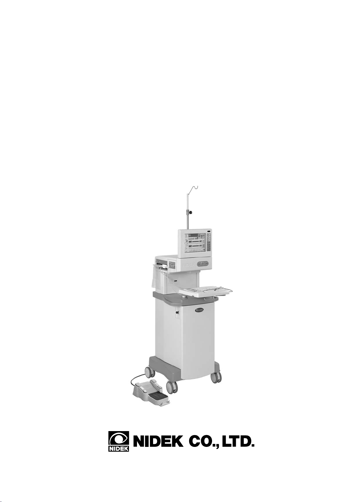
NIDEK
OPHTHALMIC SURGICAL SYSTEM
Model CV-24000
OPERATOR’S MANUAL
Page 2

* Specifications are subject to change without notice for improvement.
NIDEK CO., LTD. : 34-14, Maehama, Hiroishi-cho, Gamagori, Aichi 443-0038, Japan
(Manufacturer) Telephone: (0533) 67-6611
Facsimile: (0533) 67-6610
NIDEK CO., LTD : 6th Floor, Takahashi Bldg., No.2, 3-chome, Kanda-jinboucho
(Tokyo Office) Chiyoda-ku, Tokyo 101-0051, Japan
Telephone: (03) 3288-0571
Facsimile: (03) 3288-0570
Telex: 2226647 NIDEK J
NIDEK INCORPORATED : 47651 Westinghouse Drive Fremont, California 94539, U. S. A.
(United States Agent) Telephone: (510) 226-5700
Facsimile: (510) 226-5750
NIDEK SOCIETE ANONYME : Europarc 13, rue Auguste Perret, 94042 CRETEIL, France
(Authorized Representative) Telephone: (01) 49 80 97 97
Facsimile: (01) 49 80 32 08
2005. 3
18214-P902I
Printed in JAPAN
Page 3
BEFORE USE OR MAINTENANCE, READ THIS MANUAL.
THIS MANUAL CONTAINS ONLY INFORMATION TO UNDERSTAND
THE OPERATING PROCEDURES AND MAINTENANCE.
The Operator’s Manual contains information necessary for the operation of the NIDEK
OPHTHALMIC SURGICAL SYSTEM Model CV-24000.
This manual includes the operating procedures, cautions for safety, specifications and
maintenance instructions.
This manual complies with IEC 60601. This manual is required to correctly use this system.
Especially , the cautions for safety and operating procedures must be thoroughly understood
before using the instrument. Keep this manual handy to verify use whenever necessary .
Use of this system is limited to the cataract and vitreous surgery by qualified physicians only .
The physicians are responsible for the application of this system to various surgical techniques.
If you encounter any problems or have questions about the instrument, contact NIDEK or
your authorized distributor.
[NOTE]
There are 3 types of the CV-24000. To make a distinction, each system is abbreviated
according to the specifications and abbreviated names such as A type (or A), AP type
(or AP), and P type (or P) are used in this manual to simplify descriptions (see below).
In addition, it is possible to select the language indicated on the screen between English
and Japanese, however, in this manual, English version is presented.
Model name Types Abbreviations
For c a taract s urgery A type (or A)
CV-24000
For c atarac t and vit reous s urgeri es AP ty pe (or AP)
For vitreous surgery P type (or P )
Page 4

§
§
Table of Contents
1
INTRODUCTION .......................................................................................................1-1
1.1 Outline .......................................................................................................................1-1
1.2 Principles ................................................................................................................... 1-2
1.3 Classifications.............................................................................................................1-4
1.4 Symbol Information ....................................................................................................1-5
2
SAFETY ........................................................................................................................ 2-1
2.1 Storing, Transport, and Installation .......................................................................... 2-1
2.2 Wiring and Connection ............................................................................................2-3
2.3 During Use ............................................................................................................... 2-4
2.3.1 In general......................................................................................................... 2-4
2.3.2 Sterilization ..................................................................................................... 2-5
2.3.3 About the US handpiece and US tip ............................................................... 2-6
2.3.4 About ultrasound oscillation ........................................................................... 2-7
2.3.5 About use of the diathermy function ...................................................................2-8
2.3.6 About use of the vitreous cutter..........................................................................2-9
2.4 After Use, Maintenance, and Check............................................................................2-9
2.4.1 Cleaning and sterilization....................................................................................2-9
2.4.2 Others ............................................................................................................2-10
2.5 Disposal...................................................................................................................2-11
2.6 Safety Devices .........................................................................................................2-12
2.7 Labels......................................................................................................................2-13
§
§
3
SYSTEM DESCRIPTION............................................................................................ 3-1
4
OPERATING PROCEDURES ...................................................................................4-1
4.1 Preparation Before Surgery ...................................................................................... 4-1
4.1.1 Sterilization of instruments ............................................................................. 4-1
4.1.2 Setup................................................................................................................ 4-3
4.2 Setting and Testing Each Cassette ............................................................................ 4-5
4.2.1 For anterior single cassette --For A and AP types...........................................4-5
4.2.2 For anterior dual cassette -- For A and AP types..............................................4-14
4.2.3 For anterior/posterior dual cassette --For AP type ...........................................4-18
4.2.4 For posterior dual cassette (Posterior setting) --For A P type ............................4-26
4.2.5 For posterior dual cassette (ANT/POST setting) --For AP type .......................4-32
4.2.6 For posterior dual cassette (Dual setting) --For P type .....................................4-39
4.2.7 For posterior dual cassette (Single setting) --For P type ...................................4-45
4.2.8 Selectable mode after test................................................................................4-49
4.2.9 switch .........................................................................................4-49
Page 5

4.3 Operation Screens....................................................................................................4-50
4.3.1 Anterior mode screen (main screen) --For AP and P types ...............................4-50
4.3.2 Dia mode screen (anterior mode) --For AP and P types ...................................4-53
4.3.3 Irr mode screen (anterior mode) --For A and AP types ....................................4-55
4.3.4 US mode screen (anterior mode) --For A and AP types ...................................4-56
4.3.5 US Propedal mode screen (anterior mode) --For A and AP types ....................4-59
4.3.6 I/A mode screen (anterior mode) --For A and AP types ...................................4-64
4.3.7 I/A Propedal mode screen (anterior mode) --For A and AP types.....................4-67
4.3.8 V it mode screen (anterior mode) --For A and AP types....................................4-70
4.3.9 Posterior mode screen (main screen) For A P and P types.................................4-72
4.3.10 Dia mode screen (posterior mode) --For A P and P types ...............................4-75
4.3.11 Vit mode screen (posterior mode) --For AP and P types ................................4-77
4.3.12 Asp mode screen (posterior mode) --For AP and P types ..............................4-80
4.3.13 US PPL mode screen (posterior mode) --For A P type...................................4-82
4.3.14 Scis mode screen (posterior mode) --For AP and P types ..............................4-85
4.3.15 Small screens ................................................................................................4-87
4.3.15.1 FGX small screen..............................................................................4-88
4.3.15.2 Illum1, Illum2 small screen .................................................................4-89
4.3.16 Custom setting screen.................................................................................... 4-90
4.3.17 Program contents screen ...............................................................................4-94
4.3.17.1 Changing settings on the anterior screen .............................................4-95
4.3.17.2 Changing settings on the posterior screen .........................................4-105
4.3.18 File screen .................................................................................................. 4-111
4.4 Cleaning the Instruments ......................................................................................... 4-114
§
§
5
TROUBLESHOOTING .............................................................................................. 5-1
5.1 Error During Cassette Test .......................................................................................5-1
5.2 Error During System Test.........................................................................................5-3
5.3 Error During Use ......................................................................................................5-8
6
MAINTENANCE ......................................................................................................... 6-1
6.1 List of Consumables and Maintenance Parts ........................................................... 6-1
6.2 Replacement of Printer Paper................................................................................... 6-1
6.3 Replacement of Halogen Lamp................................................................................6-2
6.4 Replacement of Fuses...............................................................................................6-3
6.5 Cleaning ................................................................................................................... 6-5
6.5.1 Cleaning the exterior .......................................................................................6-5
6.5.2 Cleaning the LCD touch panel ........................................................................6-6
Page 6

§
7
SPECIFICATIONS ...................................................................................................... 7-1
7.1 Specifications of Each Part ......................................................................................7-1
7.2 Power Requirements and Others .............................................................................. 7-5
§
8
ACCESSORIES............................................................................................................8-1
8.1 Configurations for A Type........................................................................................8-1
8.2 Configurations for AP Type .....................................................................................8-2
8.3 Configurations for P Type ........................................................................................ 8-3
8.4 Option....................................................................................................................... 8-4
8.4.1 Anterior mode ................................................................................................. 8-4
8.4.2 Posterior mode ................................................................................................ 8-4
8.4.3 Foot pedal........................................................................................................ 8-4
Words in this manual .................................................................................... end of the manual
Page 7

§
1
1.1 Outline
NIDEK OPHTHALMIC SURGICAL SYSTEM Model CV-24000 is a system for cataract and
vitreous surgeries and has 3 available types, for cataract surgery , for cataract and vitreous surgeries,
and for vitreous surgery.
The system for cataract surgery (A type) has the functions such as the irrigation control, vacuum
pressure/aspiration flow control, ultrasound power control, anterior vitrectomy, and diathermy.
The system for cataract and vitreous surgeries (AP type) has the functions such as the posterior
vitrectomy, fluid/gas exchange, intraocular scissors driving, and intraocular illumination in
addition to the functions of the system for cataract surgery.
The system for vitreous surgery (P type) has the functions such as the vacuum pressure/aspiration
flow control, posterior vitrectomy, fluid/gas exchange, intraocular scissors driving, intraocular
illumination, and diathermy.
INTRODUCTION
These 3 systems are comprised of a main body, foot pedal, and accessories. To enhance the
usability of each function of the system, the CV-24000 adopts the followings:
(1) A color LCD touch panel and infrared wireless remote control*
values and check of the system condition.
(2) An automatic loading-type tube cassette enables you to perform quick setting and cleaning
of tubes.
(3) A built-in printer makes it possible to print surgery data of US Time/US Ener gy, vacuum
pressure, etc.
The CV-24000 is the user-friendly system whose functions of cataract and vitreous surgeries
and their operabilities are successfully combined.
1
achieve easy input of setting
*1 An infrared wireless remote control is for A and AP types only , not for P type.
Page 8

1 - 2
1.2 Principles
(a) Phacoemulsification
When a voltage is applied to an oscillator inside the US handpiece, the oscillator is vibrated
according to the amplitude and frequency of the AC voltage.
The obtained vibration is transmitted to the US tip via a trumpetlike part called as a horn.
In phacoemulsification, the AC voltage is applied to the oscillator at a ultrasound range of
frequency, and the obtained ultrasound vibration is amplified by the horn and transmitted to
the US tip. Then, the end of US tip fragmentates the lens nucleus and the emulsification is
achieved.
(b) Irrigation
The irrigation solution flows into the eye via a tube and handpiece by gravitation. Because
the irrigation pressure changes according to the height between the eye to be operated and the
fluid level of the irrigation bottle, the pressure can be controlled by raising or lowering the
motorized pole, which the irrigation bottle is hung on, with the switch operation.
Furthermore, the built-in pinch valve supplies and stops the irrigation solution.
(c) Aspiration
When the peristaltic pump rotates, the fluid inside the aspiration tube is pressed out by the
roller, the vacuum pressure is generated, and substance inside the eye is aspirated. In other
words, as the volume of pressed-out fluid is equal to the flow rate, it can be controlled by the
rotation speed of pump.
In addition, the pressure sensor monitors and controls the vacuum pressure.
(d) Vitrectomy
When the air pressure generated by the built-in air compressor or external compressed air
source is intermittently supplied to the vitrectomy cutter, the inner blade at the tip of the cutter
is vibrated. The cutting speed is controlled by the intermittent period of the supplied air
pressure which is controlled by the special solenoid valve.
(e) Intraocular scissors
The scissors are opened or closed when the air pressure generated by the built-in air compressor
or external compressed air source is intermittently supplied to the intraocular scissors. The
cutting speed is controlled by the intermittent period of the supplied air pressure which is
controlled by the special solenoid valve. It is also possible to open or close the scissors by the
air pressure according to the pressing amount of foot pedal.
Page 9

(f) Fluid/gas exchange
When the compressed air adjusted by the built-in small pump is conveyed to the inside of the
eye via sclera, the air pressure presses the fluid out of the vitreous cavity and the pressed-out
fluid is drained. Then, the fluid is exchanged with gas.
(g) Intraocular illumination
The illumination adopts the halogen lamp as a light source, whose infrared ingredients are
eliminated by the filter inside the illumination unit in advance. The illumination is led to the
inside of the eye by the acrylic light guide probe.
(h) Diathermy
The Joule heat is generated when the electrical current is applied to tissue. Diathermy is to
dehydrate, coagulate the tissue with the Joule heat, stop bleeding, or prevent bleeding of the
incised area.
(i) Fragmentation
This is used for the pars plana lensectomy. From the incision made at the pars plana, the
special US tip is inserted into the vitreous cavity and the lens is fragmented and aspirated by
the ultrasound oscillation of the US tip.
1 - 3
Page 10

1 - 4
1.3 Classifications
[Protection method against electric shock] Class I
CV-24000 is classified into a Class I system.
A Class I system is a system in which the protection against electric shock does not rely on
basic insulation only, but which includes an additional safety precaution in such a way that
means are provided for the connection of accessible conductive parts to the protective (earth)
conductor in the fixed wiring of the installation in such a way that accessible conductive parts
cannot become live in the event of a failure of the basic insulation.
[Degree of protection against electric shock] Type BF applied part, Type B applied part
The diathermy of CV-24000 is classified into a Type BF applied part and others are classified
into a Type B applied part.
A Type BF applied part is isolated from other parts of the medical/electrical equipment to
such a degree that no current higher than the patient leakage current allowable in single fault
condition flows if 1.1 times of maximum rated supply voltage is applied between the applied
part and earth.
A Type B applied part contains an internal electrical power source providing an adequate
degree of protection against electric shock particularly regarding;
- allowable leakage currents
- reliability of the protective earth connection (if present)
[Degree of protection by the enclosure]
The main body of the CV -24000 is classified as IP20, and the foot switch is classified as IPX8.
An IP20 system is protected against an ingress of solid foreign objects, such as a finger having a
diameter of 12.5mm or greater, however , it is an ordinary system without protection against an
ingress of liquids. Be careful not to get water on the main body and control box.
An IPX8 system is a waterproof system provided with an enclosure preventing the effects caused
by immersion in water.
[Sterilization methods recommended by the manufacturer]
Non-sterilized instruments of CV-24000 should be autoclaved under 132ºC.
[Degree of safety in the presence of flammable anesthetics and/or flammable cleaning agents]
CV-24000 should be used in an environments where no flammable anesthetics and/or
flammable cleaning agents are present.
[Mode of operation]
CV-24000 is an intermittent operation system.
[Classification by transference]
CV-24000 is classified into a transportable system.
Page 11
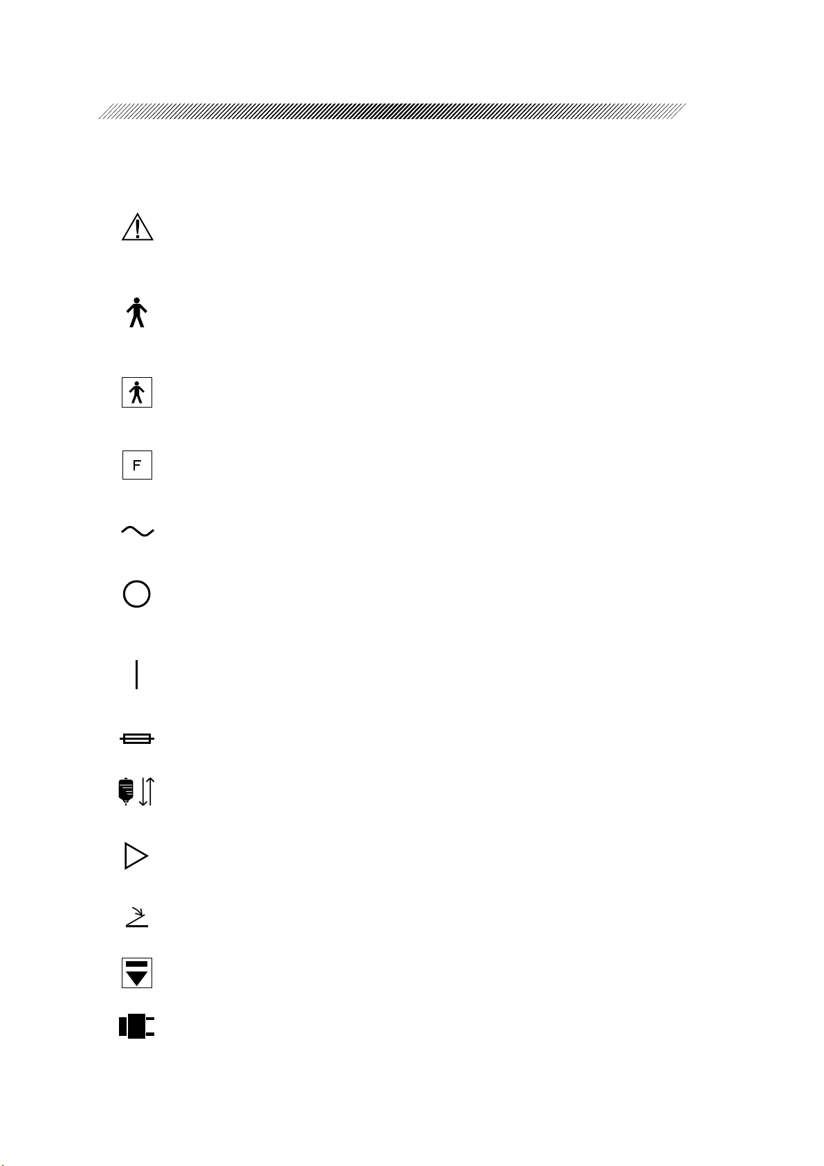
1.4 Symbol Information
This symbol indicates that important descriptions related to operation or maintenance
are contained in the operator’s manual and that an operator must refer to the operator’s
manual prior to operation and maintenance.
This symbol indicates that the degree of protection against electric shock is a type B
applied part.
This symbol indicates that the degree of protection against electric shock is a type BF
applied part.
This symbol indicates that the applied part is non-grounding type according to the high
frequency.
1 - 5
This symbol indicates that the system should be operated only with alternating current.
This symbol indicates the master switch setting. When the switch is flipped to the
symbol side, the power is not supplied to the system.
This symbol indicates the master switch setting. When the switch is flipped to the
symbol side, the power is supplied to the system.
This symbol indicates the fuse rating.
This symbol indicates the function to raise or lower the irrigation pole.
This symbol indicates the slot where the memory card is inserted. When inserting the
memory card, align the symbol on the memory card with the one on the main body.
This symbol indicates the connector to which the foot pedal shall be connected.
This symbol indicates the switch to eject a cassette.
This symbol indicates the switch to display the Dia mode screen.
Page 12

1 - 6
This symbol indicates the switch to display the Irr mode screen. The symbol on the
cassette indicates the connection line with the irrigation bottle.
This symbol indicates the switch to display the US mode screen. The symbol on the
cassette indicates the connection line with the US handpiece.
This symbol indicates the switch to display the I/A mode screen. The symbol on the
cassette indicates the connection line with the I/A handpiece.
This symbol indicates the switch to display the Vit mode screen.
This symbol indicates the switch to display the Asp mode screen.
This symbol indicates the switch to display the Scis mode screen.
This symbol indicates the switch to indicate the setting of the intraocular illumination.
This symbol indicates the switch to indicate the setting of the gas exchange.
This symbol indicates the effective number of use and means the prohibition of reuse.
This symbol indicates the method of sterilization and means that the radiation sterilization
has been performed.
This symbol indicates the time period over which the part can be used safely.
Page 13

§
2
In this manual, Signal Words are used to designate a degree or level of safety alerting,
whose definitions are as follows.
WARNING: Indicates a potentially hazardous situation which, if not avoided,
could result in death or serious injury.
CAUTION: Indicates a potentially hazardous situation which, if not avoided,
may result in minor or moderate injury or property damage accident.
Some items described in WARNING and CAUTION may cause a serious
accident according to the circumstances. Follow all the instructions mentioned below
since they are very important.
2.1 Storing, Transport, and Installation
SAFETY
CAUTION
• Prior to storage, verify that the storage area meets the following conditions:
- Not exposed to ultraviolet rays and direct sunlight.
- Not splashed with rain or water .
- No chemical agents and organic solvent are present.
- No salt, sulfur content, toxic gas or large amounts of dust is contained in the air .
- Level and stable without vibration and shock.
- The following environmental conditions in storage and transport ( packed condition) specified
in the specification are met.
Temperature: -10 to 60ºC / Humidity: 30 to 90% (non-condensing)
Atmospheric pressure: 700 to 1060 hPa
• Lower the irrigation pole to the lowest position before transporting the system.
In addition, fold the irrigation hook and store it inside the pole.
Failure to do so may bump the pole or catch the hook.
• Transport the system after hanging the foot pedal and cords on their special hooks on the
stand.
If the system is transported without the foot pedal and cords properly stored, the cords
may be caught causing a fall of system and break of cords.
Page 14

2 - 2
CAUTION
• Hold the handle on the stand when transporting the system. Avoid sudden operation at
the start/stop of transportation.
Otherwise, the system may fall down and an injure or system malfunction may result.
• Never drag the system by holding the power cord or cable of the foot pedal when
transporting the system.
Otherwise, the system may fall down and an injure or system malfunction may result.
• If the temperature differs substantially before and after the transport, condensation may
occur in the system. After transport, confirm that the system is at room temperature
before turning on the power of the system.
If the power is turned on while the condensation is happening, malfunction or electric
shock may result from short-circuit.
• Prior to installation, verify that the installation area meets the following conditions:
- Level and stable without vibration and shock.
- Not exposed to liquids such as water.
- No flammable gases (including anesthetic gas) or solvents is present.
- No large amount of dust is contained in the air .
- Not exposed to direct air-conditioning flow .
- Not exposed to direct sunlight or ultraviolet rays.
- The following environmental conditions in installation (unpacked condition) are met.
T emperature: 10 to 30ºC / Humidity: 30 to 75% (non-condensing)
Atmospheric pressure: 860 to 1060 hPa
• Install the system where it is not exposed to strong electromagnetic waves during operation.
Strong electromagnetic waves may cause the system to malfunction.
• Install the system so as not to block the ventilation hole on the cover of the main body.
The cooling fan cannot radiate heat properly and the system may be adversely affected.
Page 15

2.2 W iring and Connection
CAUTION
• Use a grounded power outlet which meets the power requirements labeled on the system.
Otherwise, the system may not perform sufficiently or may be damaged. If the power outlet is
not a grounded type and a leakage of current occurs because of a system malfunction, an
electric shock may result.
Moreover, it may cause electromagnetic interference for other devices or hum noise.
• Do not overload the electrical outlet.
Abnormal heat generation may occur and result in fire.
• Always pull the plug, not the cord, when unplugging the power cord.
The cable core may break, and an ignition or electric shock due to a short-circuit may
result.
• Be sure not to get the power cord pinched under a heavy object such as the system.
The cable sheath may break, and a short-circuit or electric shock may result.
2 - 3
• If the inside wires of the power cord are exposed, do not continue using the system but
unplug the power cord and contact NIDEK or your authorized distributor.
An electric shock or fire may occur.
• Never remove the cover that holds the power cord except in order to replace the fuse.
If the power cord is disconnected during the operation, the result of the surgery may be
seriously affected.
• After inserting the cable plug of the foot pedal, lock the plug with the ring to hold it.
If the cable plug becomes loose during the operation, the result of the surgery may be
seriously affected.
• Securely connect the plug of connecting cables for the handpiece, etc. and the luer connector
for the tube, etc. following the instructions on this operator’s manual.
Otherwise, the system may not work normally and an accident or malfunction may occur.
• Hold the plug, not the cable or cord, to when connecting or disconnecting the US handpiece or
diathermy cord.
If the inside wires of the cable or cord break, ultrasound oscillation and diathermy become
impossible.
Page 16

2 - 4
2.3 During Use
2.3.1 In general
CAUTION
• Never use this system for purposes other than cataract surgery.
If any accident occurs because of use for other purposes, NIDEK assumes no
responsibility.
• Prior to the first use of the system each day, perform the system test and function checks referring
to the Pre-operation check manual (18214-P912A). NIDEK assumes no responsibility if failure
occurs during the operation of each mode without performing the test and checks.
• If any abnormality occurs to the system, do not touch the inside of the system. Unplug the power
cord from the power outlet and contact NIDEK or your authorized distributor .
• In case of failure of the system, take backup measures for the surgery to be performed.
• Do not modify or touch the inside of the system.
T o do so may cause an electric shock or system malfunction.
• This system is provided with a T ype B applied part. A void the combined use of this system and
other systems which contact the patient during use.
• Do not touch the LCD touch panel with anything other than fingers during operation. Do not
touch 2 or more places at the same time.
T ouching with a hard or sharp object (such as ball-point pen) may scratch the panel. If 2 or
more places are touched at the same time, a system malfunction may occur .
• Make sure that the LCD touch panel is not exposed to the direct sunlight or ultraviolet
rays during operation.
The LCD touch panel may be damaged.
• Contents of cassette pack and connection set are disposable items. Never open the package
until just before use. Be sure to dispose of them after use and never reuse them.
• Use the specified infusion tube (another package including the cassette pack) only.
Using unspecified infusion tube may cause an insufficient irrigation flow and the anterior
chamber or eyeball to collapse.
• When using the optional I/A tip (φ 0.5mm), pay special attention to the aspiration pressure
so that it does not become so high.
If the I/A tip (φ 0.5mm) is used at the setting of the aspiration pressure over 300 mmHg,
the anterior chamber may become shallow at the time of aspiration.
Page 17

2 - 5
CAUTION
• Never let a hard substance contact the ends of tips (especially US tip), diathermy forceps,
vitrectomy cutter and intraocular scissors.
They may be deformed or cannot be used any longer.
• The height of IV pole indicated on the screen is intended for use of a 500 mL glass bottle.
Using other bottles may cause a gap between the indication and actual heights.
• Never splash water onto the main body . Besides, be sure not to splash water onto the foot
pedal as much as possible.
Otherwise, a system malfunction or electric shock may result.
• Tray is to place the surgical instruments such as handpiece, etc. during surgery.
Do not place heavy objects or rest your weight on the tray.
Otherwise, it may be deformed or the system may fall down.
2.3.2 Sterilization
WARNING
• Be sure to sterilize all accessories that need to be sterilized before the surgery.
Otherwise, the physician, patient or assistant may be infected.
CAUTION
• Sterilize the accessories according to the specified method. (For details, refer to “4.1.1
Sterilization of instruments” (p.4-1).)
If not, they may be deformed or damaged.
• Confirm that no dirt or foreign object is on the instruments before sterilization. If dirt or
foreign object is found, remove it be cleaning.
(For the details of cleaning, see “4.4 Cleaning the Instruments” (p.4-109).)
• Autoclave the parts observing their useful lifetime and the number of times they can be
used that are written on the package.
If the useful lifetime or the number of uses is exceeded, the parts may have problems
and may interfere with the surgery.
Page 18

2 - 6
2.3.3 About the US handpiece and US tip
CAUTION
• Never modify the US handpiece or the US tip by bending, cutting, or engraving them.
The US handpiece or the US tip may break or malfunction.
• When autoclaving the US handpiece, always use a vacuum drying type sterilizer.
Using a sterilizer other than that of a vacuum drying type may damage or accelerate the
deterioration of the US handpiece.
• Use only the NIDEK US tip for the US handpiece. Never use the I/A tip or other manufacturers’
US tips.
Normal ultrasound oscillation may not be achieved. NIDEK assumes no responsibility
for accidents caused by use of unspecified tips.
• Confirm that the plug of the US handpiece is completely dry before connecting it to the
US connector.
Failure to do so may cause an electric shock and damage to the US handpiece.
• Connect the US tip to the US handpiece, and the cable plug of the US handpiece to the US
connector of the main body securely.
Insecure connections may cause ultrasound oscillation failure and poor electrical contact.
• Never immerse the US handpiece and plug in a liquid.
Ultrasound oscillation failure or poor electrical contact may result.
• Use the US handpiece at ordinary temperatures. After autoclaving, leave it for approximately
15 minutes or more and check that it has cooled down before use.
Otherwise, burns may occur .
• If abnormal heat is generated from the US handpiece or US tip, do not touch the internal
structure of the system. Disconnect the US handpiece from the system and contact NIDEK or
your authorized distributor.
The untrasound may not be oscillated and burns may occur to the patient or the user .
Page 19

2.3.4 About ultrasound oscillation
CAUTION
• Never touch the US tip during ultrasound oscillation.
Injuries may occur.
• Never let the end of the US tip contact other medical devices (instrument for nuclear
segmentation, etc.) during ultrasound oscillation.
The US tip or other medical devices may break and generate pieces of metal.
• Before ultrasound oscillation, check the setting values (ultrasound output power, aspiration
pressure, aspiration flow rate, US control mode, etc.). During ultrasound oscillation,
observe the motion of the US tip.
Otherwise, the US tip may be damaged beyond repair.
• When oscillating the ultrasound, make sure that the US tip operates with sufficient irrigation
and aspiration (the US tip must be in the test chamber filled with the irrigation solution or
in the eye).
Ultrasound oscillation without irrigation and aspiration may damage the US tip beyond
repair.
2 - 7
• During ultrasound oscillation, do not move the US tip close to a side of the incision or
perpendicular to the dome of the cornea.
The area around the incision may be burned.
• If the ultrasound is oscillated while the US tip is in the viscoelastic, the viscoelastic
blocks the irrigation flow. It causes insufficient cooling of the US tip and, as a result, a
burn.
Create a space filled with the irrigation solution between the lens and the viscoelastic in
advance. Perform ultrasound oscillation with the irrigation and aspiration ports in the
space.
• In phacoemulsification, a phenomenon, known as cavitation, may occur in which the ultrasonic
vibration forms bubbles from the gas in the irrigation solution that flows through the US handpiece.
If this bubbles enter the patient’s eye, they may obstruct the physician’ s view and interfere with
surgery . To control the formation of bubbles, use the pulse mode or other methods not to use
ultrasound more than necessary . If the bubbles enter the patient’ s eye, aspirate them using the
devices such as the US tip to secure the physician’s view .
Page 20

2 - 8
2.3.5 About use of the diathermy function
WARNING
• When using the diathermy function for patients with a cardiac pacemaker or its electrode
implanted, consult the cardiac surgeon or manufacturer of the pacemaker.
The function of the pacemaker may be affected or the pacemaker may be damaged.
CAUTION
• The diathermy forceps and pencil, and the cord that are standard accessories can be used
exclusively for the CV-24000. Do not connect them to unspecified terminals or other
manufacturer’s bipolar/monopolar device.
Especially , if the diathermy cord is connected to the monopolar output terminal, unexpected
output voltage may be generated and serious adverse events may occur .
• Never modify the diathermy forceps, pencil, or cord by bending, cutting, or engraving them.
The diathermy forceps, pencil, or cord may break or malfunction.
• Connect the diathermy forceps or pencil and the cord securely.
Insecure connections may cause coagulation failure and poor electrical contact.
• When using the diathermy function, observe the following conditions to avoid a burn or
electric shock:
- Use the diathermy forceps and pencils, and the cords that are in the standard accessories.
- Make sure that the diathermy cord is not deformed (change in shape or cracks).
- Flammable gas should not be in the air.
- The diathermy power selected should be as low as possible for the intended purpose.
- The patient should not come into contact with metal parts which are earthed or which
have an appreciable capacitance to earth (for example operating table supports, etc.).
- The diathermy cord should be positioned in such a way that contact with the patient
or other cords is avoided.
- When physiological monitoring equipment is used simultaneously on the same patient,
any monitoring electrodes should be placed as far as possible from the patient’s eye.
- Use monitoring systems incorporating high frequency current-limiting devices.
Page 21

2.3.6 About use of the vitreous cutter
CAUTION
• Observe the following points when using the vitreous cutter to avoid trouble during the surgery:
- Confirm the connections of the drive/aspiration tube and the leur adapter beforehand.
- Before using the vitreous cutter, put the needle part in the water and check the operation. If
it malfunctions, replace it.
• Even after the check described above, performance of the vitreous cutter may decrease due to
failure of the system infrequently . Before moving the tip of the cutter away from the incision,
check that the incision has been made completely .
If the tip of the cutter is moved away from the incision when the incision is incomplete, retinal
tear may result.
2 - 9
2.4 After Use, Maintenance, and Check
2.4.1 Cleaning and sterilization
CAUTION
• Observe the following points in the first cleaning after use:
- Use distilled water for the first cleaning instead of tap water to avoid rust or stain.
- T o avoid rust, use only enzyme detergent for cleaning. (Refer to the user’s guide attached to
the detergent before use.)
- T o avoid rust, wash the cleaned parts sufficiently and dry them as quickly as possible.
• Observe the following points in the first sterilization after use:
- T o avoid rust, use only glutaral preparation for cleaning. Do not use other preparations such
as phtharal preparation. (Refer to the user’s guide attached to the preparation before use.)
- T o avoid inflammation by touching the sterilized parts, wash them sufficiently and dry them
as quickly as possible. (Refer to the user’s guide attached to the preparation before use.)
• Observe the following points in the ultrasonic cleaning:
- Do not subject the US handpiece and diathermy cord to the ultrasonic cleaning to avoid
break of terminal or deterioration of the electrical characteristics that may occur depending
on the conditions.
- To protect the ends of the US tip, I/A tip, and diathermy forceps, put the rubber cap on
them before using the ultrasonic cleaning for them.
Page 22

2 - 10
CAUTION
• Observe the following points in the cleaning and sterilization of the US handpiece and diathermy
cord:
- T o avoid contact failure from short circuit or rust, do not immerse the parts in the detergent
or sterilizing solution.
- Wipe the exterior of the US handpiece and the diathermy cord with gauze or absorbent
cotton soaked in the detergent or sterilizing solution and wrung sufficiently . Do not wipe
them with excessive force.
- T o avoid break of wire, wipe the areas where the cable and cord are attached with special
care.
- To avoid break of wire, do not press or pull the cables and cords forcefully when wiping
them.
2.4.2 Others
CAUTION
• If the system will not be used for a long period of time, unplug the power cord from the power
outlet.
If dust settles on the plug of the power cord, the dust absorbs moisture and may cause a
short-circuit and fire.
• If the system is not being used, turn OFF the power and put the dust cover on the system.
Dust settles on the system and makes it dirty.
• Use the specified fuses only.
Otherwise, the system may not perform sufficiently and a system malfunction or fire may
result.
• Use the specified lamp for intraocular illumination.
Otherwise, the system may not perform sufficiently and a system malfunction or fire may
result.
• Use the specified printer paper.
Otherwise, data cannot be printed out or the printer paper may be jammed.
Page 23

2 - 11
CAUTION
• When sending the system back to NIDEK for repair or maintenance, wipe the surface of
the system (except the LCD touch panel) with a gauze dampened with glutaral preparation.
Wipe the LCD touch panel with a gauze dampened with alcohol.
Then, wipe the part which has been cleaned with glutaral preparation with a gauze dampened
with sodium hypochlorite.
Failure to do so may cause personnel who repair or preform maintenance to become infected.
• Ask NIDEK for inspection of the system once a year.
According to the frequency of use, the part which drives the irrigation pole may need to be
greased.
• Only service technicians properly trained by NIDEK can modify and repair the system.
NIDEK assumes no responsibility for accidents caused by improper repair.
2.5 Disposal
CAUTION
• Follow local governing ordinances and recycling plans regarding disposal or recycling of
device components when disposing of the system.
Especially , the disposing method of lithium batteries varies according to the government.
This system has electric circuit boards with lithium batteries in the main body. When
disposing of the board, follow the instruction of the government.
• When disposing of packing materials, sort them by the materials and follow local governing
ordinances and recycling plans.
• When disposing of the main body and foot pedal, wipe the surface of them with a gauze
dampened with rubbing solution such as glutaric aldehyde.
Failure to do so may cause personnel who are involved in the disposal to become infected.
• When disposing of accessories such as tips, tubes, handpiece, forceps and scissors, follow
the recommended disposal procedure for medical wastes such as needles from an injection
or blood infusion tubes as specified by your local medical institution and ordinances
against environmental pollution.
Page 24

2 - 12
2.6 Safety Devices
[TEST mode]
This mode is to check the conditions of each part of the system before surgery , and performing
this test prevents troubles from occurring during surgery.
CV-24000 automatically checks the following items according to the inserted cassette by
pressing each switch in the “Test” box indicated on the LCD touch panel.
• Cataract surgery...............................Motion check of irrigation and aspiration
* When the US handpiece is connected to the
system, ultrasound output is also checked.
• Vitreous surgery ..............................Motion check of aspiration
* When the US handpiece is connected to the
system, ultrasound output is also checked.
• Cataract & Vitreous surgeries
.................Anterior screen: Motion check of irrigation and
aspiration
* When the US handpiece is connected to the
system, ultrasound output is also checked.
Posterior screen: Motion check of aspiration
* When the US handpiece is connected to the
system, ultrasound output is also checked.
If an abnormality is found by checking these items, error and contents are indicated on the
display.
[Self-diagnostic function]
The system automatically checks the connecting condition of each part and own functions
even during surgery. If an abnormality occurs, error and contents are indicated on the display
and the beep sound is produced. (The beep sound stops by pressing the part indicated as an
error.)
[Aspiration pump]
A peristaltic pump system which controls the aspiration flow rate by pressing the aspiration
tube is adopted in order to achieve the ease of operation and stable aspiration.
Page 25
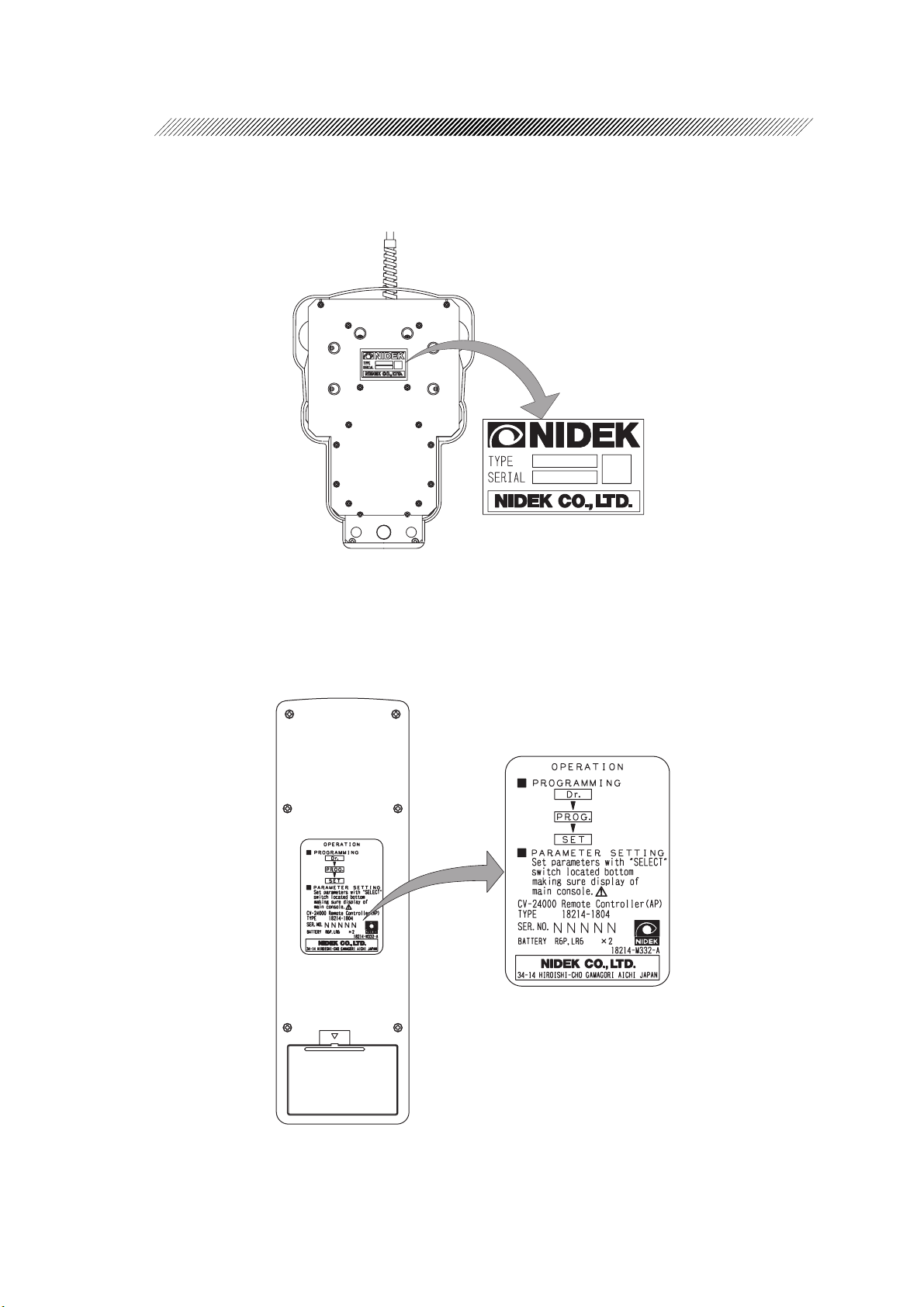
2.7 Labels
In order to call the operator’s attention, the appropriate warning labels are affixed to the designated
locations on the system.
[Rear side of the main body (AP type)]
2 - 13
450
For AC 100V/AC 115V
For AC 230V
550
Page 26
2 - 14
[Bottom side of the foot pedal]
[Rear side of the remote control (AP type)]
Page 27

2 - 15
This page is intentionally left blank.
Page 28
§
SYSTEM DESCRIPTION
3
[Front side of the main body (AP type)]
LCD touch panel
Photodetector of
remote control
Switch panel
Plugs for light guide
Speaker
Tray
Tray UP/DOWN knob
Storage box
Caster lock
Page 29
3 - 2
LCD touch panel
Displays various operation screens, setting
values of each mode, and present system conditions.
By pressing the indicated operation switch, it
is possible to change the mode and input/
change the setting value.
Photodetector of remote control
Receives the infrared signal from the remote
control.
Do not block the anterior part of this photodetector . (P type does not have this function.)
Switch panel
Indicates available modes for each system
type. By pressing these switches on this panel,
the corresponded mode is selected.
Available modes for each system are as follows.
Tray UP/DOWN knob
Used to adjust the height of tray . While raising this knob with one hand, adjust the height
of tray by holding the tray arm with the other
hand.
Releasing this knob fixes the adjusted height.
Storage box
The door of this storage box can be opened
and closed with the knob.
Caster lock
Used to transport the system and fix the position of the system. The caster is locked by
lowering the lever, and it is released by raising the lever .
Type Available m ode s
A type Dia, Irr, US, I/A, Vit
AP type
P type
Dia, Irr, US, I/A, Vit, Scis,
Illum1, Illum2, ON/OFF of FGX
Dia, Asp, Vit, Scis, Illum1,
Illum2, ON/OFF of FGX
Plugs for light guide
For AP and P types, the connector of the light
guide for intraocular illumination is inserted
here.
Speaker
This is for a voice guidance, operation sound,
and beep sound.
T ray
The remote control, each handpiece for US,
I/A, and irrigation, vitrectomy cutter, intraocular scissors, and light guide probe are placed
here.
Be sure not to place heavy object or rest your
weight on this tray.
Page 30
3 - 3
[Rear side of the main body (AP type)]
Back light control
Irrigation pole
Irrigation pole height
fixing knob
Irrigation pole UP/DOWN
switch
Memory card slot
Volume control
PRINT/FEED switch
Printer cover
Hook for foot pedal cable
Hook for foot pedal
Hook for power cord
Connector for external
pressure source
Inlet with fuse
Inlet with fuse
Inlet with the built-in fuse carrier.
The power cord is connected here.
When the power is not supplied to the system, there is a fear that fuses inside the carrier may be burnt.
Foot pedal connector
Pilot lamp
Power switch
Connector for external pressure source
When using a compressed air or nitrogen gas
cylinder as a driving source for the vitrectomy
cutter and intraocular scissors with AP or P
type, the external pressure source is connected
here.
Page 31

3 - 4
Memory card slot
A memory card for storing data of surgery
conditions is inserted here.
Irrigation pole UP/DOWN switch
Used to adjust the height of irrigation pole.
By pressing the side, the irrigation pole is
raised, and it is lowered by pressing the
side.
Irrigation pole height fixing knob
When the adjustable range of the height is not
enough with the irrigation pole UP/DOWN
switch, loosen this knob and adjust the height
of irrigation pole.
Irrigation pole
This is for hanging an irrigation bottle.
The height of bottle can be adjusted with the
electric switch.
The irrigation bottle is hung on the hook at
the top of this pole.
Printer cover
A printer is built in this cover. When “PUSH
OPEN” at the top of this cover is pressed, the
cover opens and it becomes possible to re-
place the printer paper.
Hook for foot pedal cable
A foot pedal cable is hung on here when the
system is transported and stored.
Hook for foot pedal
A foot pedal is hung on here when the system
is transported and stored.
Hook for power cord
A power cord is hung on here when transporting and storing the system.
Foot pedal connector
A connector of the foot pedal is connected
here.
Back light control
Used to adjust the light quantity of the back
light for LCD touch panel. Turning this control clockwise brightens the back light, and
turning this control counterclockwise darkens the back light.
Volume control
Used to adjust the volume of speaker. Turning this control clockwise turns up the volume, and turning this control counterclockwise turns down the volume.
PRINT/FEED switch
When the PRINT switch is pressed, the surgery data displayed on the LCD touch panel
is printed out.
When the FEED switch is pressed, the printer
paper is fed. This switch is also used when
the printer paper is replaced.
Pilot lamp
Lights up when the power is supplied to the
system by turning ON ( | ) the power switch.
Power switch
Used to turn ON/OFF the power of the system. Pressing the “ | ” side turns ON the
power, and pressing the “ ” side turns OFF
the power.
Page 32

3 - 5
[Left side of the main body (AP type)]
FGX connector
Cassette slot
CASSETTE EJECT
switch
TESTING CASSETTE
indicator
DIA connector
VIT connector
US connector
SCIS connector
Page 33

TESTING CASSETTE indicator
Blinks during a test.
CASSETTE EJECT switch
To eject the cassette, press this switch. After
the lock of cassette is unloaded, the cassette
can be pulled out.
Cassette slot
A cassette is inserted here.
FGX connector
When fluid/gas used with AP or P type is exchanged, a tube connector for fluid/gas exchange is connected here via a microfilter.
DIA connector
A banana plug of the diathermy connecting
cord is connected here.
3 - 6
VIT connector
A connector of the tube for driving the
vitrectomy cutter is connected here.
US connector
A connector plug of the connecting cable for
US handpiece is connected here when the US
handpiece is used with A or AP type.
SCIS connector
When the intraocular scissors is used with AP
or P type, a connector for driving the intraocular scissors is connected here.
Page 34

3 - 7
[Foot pedal]
Upper left switch
Left kick switch
Lower left switch
Main pedal
Upper right switch
Right kick switch
Lower right switch
Functions of each switch on the foot pedal can be changed with program setting. Here, the
factory settings are described. (As for the change of foot switch patterns and the operation of
each foot pedal position, see pages 3-10 and 3-11.)
* The factory setting is indicated with “Preset” on the LCD touch panel.
Lower left switch
Used to switch the mode.
In the anterior mode, every time this switch
is pressed, the mode during surgery is changed
Upper left switch
When this switch is pressed while the diathermy
output is possible, the diathermy is output with
the set output power.
in the following order; Dia → Irr → US → I/
A → Dia → .
In the posterior mode, the mode during surgery is changed in the following order; V it →
Upper right switch
While this switch is pressed, the irrigation pole
is raised.
ASP → Vit → .
Left kick switch
Used to reflux.
Page 35

3 - 8
Right kick switch
In the anterior mode, the modulation is changed in the following order; US1 → US2 → (US3 →)
US1 → , when the US mode is selected. When the I/A mode is selected, the modulation is
changed in the following order; I/A1 → I/A2 → (I/A3 →) I/A1 → .
In the Vit mode, the state of vitrectomy cutter is changed between READY and OFF with this
switch.
In the posterior mode, this switch changes the state of vitrectomy cutter between READY and
OFF when the V it mode is selected. When the SCIS mode is selected, the insert mode is changed
between ON and OFF with this switch.
If the US mode is selected, the ultrasound oscillation is changed between ON and OFF with this
switch.
*Whether US3 or I/A3 mode can be used or not depends on the program setting.
Lower right switch
While this switch is pressed, the irrigation pole is lowered.
Main pedal
Controls the operation such as start/stop of irrigation, aspiration, ultrasound oscillation, vitrectomy
cutter, and diathermy in the anterior mode.
In the posterior mode, it controls the operation of aspiration, vitrectomy cutter, intraocular scissors, and diathermy.
Followings are the operation of each foot pedal position.
[In anterior mode]
Mode
Position
0
1
2
3
Mode
Position
0
1
2
3
Dia Irr US US (Propedal)
-- - -
- Irrigation Irrigation Irrigation + Aspiration
Diathermy Irrigation + Aspiration Irrigation + Aspiration + US
I/A I/A (Propedal) Vit
Irrigation Irrigation + Aspiration Irrigation
Irrigation + Aspiration Irrigation + Aspiration Irrigation + Aspiration + Cutter
↑
↑
↑↑
-- -
Irrigation + Aspiration + US Irrigation + Aspiration + US
Irrigation + Aspiration
* ON/OFF of “FreeFlow” has higher priority in the irrigation setting.
* Cutter operation in V it mode depends on the setting of Ready/Off.
↑
Page 36

3 - 9
[In posterior mode]
Mode
Position
OFF
ON
Mode
Position
OFF
ON
Dia Vit Asp
---
Diathermy Aspiration + Cutter Aspiration
US Scis Auto Scis Proportional
-- -
Aspiration + US Scissors cutting operation Scissors linear operation
* Cutter operation in V it mode depends on the setting of Ready/Off.
* Ultrasound oscillation in US mode is performed only when the right kick switch is ON during
ultrasound oscillation.
Page 37

3 - 10
[Foot switch patterns]
To change the function of each foot switch, press the switch or
to switch on the screen indicating each foot switch
function, then select the desired pattern. (As for the changing method, see pages 4-97
and 4-103.)
The table below shows the function of switches in each pattern.
Upper left switch
Left kick switch
Lower left switch
Main pedal
Upper right switch
Right kick switch
Lower right switch
Switch
Upper left switch Diathermy output Diathermy output Diathermy output Diathermy output Reflux
Left kick switch Reflux
Lower left switch M ode s wi t ching Mode switc hi ng
Upper right swi t ch
Right kick switch
Lower right swi t ch
Pattern
Preset Pattern 1 Pattern 2 Pattern 3 Pattern 4 Pattern 5
FreeFlow
ON/OFF
Anterior: Switching the Modulation, Cutter READY/OFF
Posterior: Cutter READY/OFF, Scissors insert mode ON/OFF, US oscillation ON/OFF
Reflux
FreeFlow
ON/OFF
POLE UP
POLE DOWN
FreeFlow
ON/OFF
Reflux Mode switc hi ng M ode switc hi ng
FreeFlow
ON/OFF
FreeFlow
ON/OFF
Reflux
Switch
Upper left switch Diat hermy output Diathermy output Diatherm y output
Left kick switch Reflux Vit1 ⇔ Vit2 Vit1 ⇔ Vit2
Lower left switch Vit1 ⇔ Vit2 Mode switching
Upper right s wit ch
Right kick switch
Lower right s wit ch
Pattern
Anterior: Switching the Modulation, Cutter READY/OFF
Pos t eri or: Cut t er RE A DY / OF F , Scis sors ins ert mode ON/OFF, US oscillat i on ON/ OF F
*Pattern 6 *Pattern 7 *Pattern 8
FGX
ON/OFF
POLE UP
POLE DOWN
* Pattern 6 to 8 are for vitreous surgery.
Page 38

3 - 11
[Switch of main pedal position]
The position of main pedal is switched between Position 0 and Position 3 according to
the pressing amount. (The illustration below shows each switching position.)
You feel a click just before the position is switched by holding the main pedal down.
The reason why there is an overlap between positions is to surely perform the switching
operation with the main pedal by setting different switching positions between the
pressing and releasing of the pedal.
%
Page 39

[Remote control]
Type of remote control varies between A and AP types. Switches whose name and positions
are the same have the same functions. (P type does not have a remote control.)
Each switch is positioned on the color-coded sheet according to its function.
Here, the descriptions are mainly for AP type.
3 - 12
[AP type] [A type]
Page 40

3 - 13
LCD monitor
Displays the name of pressed switch. Normally, the shift code (“RC 1”, “RC 2”, “RC 3”, “RC
4”) of the remote control is indicated.
Owing to the auto-power-off function, the power is turned OFF when no operation is executed
for 30 minutes. The “OFF” indication starts blinking 1 minute before the power is automatically
turned OFF.
The “BATT” indication appears when the amount of remaining battery time becomes small.
DR./PROG./SET switch
Used to change Doctor/Program.
When the DR. switch is pressed, the selected DR. being highlighted appears in the small screen
for the change of Doctor . Keep pressing the DR. switch until the desired Doctor is highlighted,
and press the SET switch to determine.
To change the Program, use the PROG. switch in the same manner.
* “Preset” means the factory setting.
* DR. cannot be changed on the screens during surgery.
POWER switch
Turns ON/OFF the power of the remote control.
ANT/POST switch (only for AP type)
Displays the main screen for Anterior/Posterior mode.
The main screen for Anterior mode appears by pressing the ANT switch, and the one for Posterior mode appears by pressing the POST switch.
When these switches are pressed on the screen during surgery , both switches works as the “Exit”
switch.
TEST switch*
2
Used to start the system test.
Mode selection switch*
2
Used to display each mode screen. The function is the same as switches on the switch panel
which is on the right side of LCD touch panel.
* ASP switch and SCIS switch are only for AP type.
PRINT/CLEAR switch
By pressing the PRINT switch, the surgery data can be printed out.
By pressing the CLEAR switch, the surgery data is cleared.
*2 By pressing the TEST switch, the message “US, V it, Dia?” is displayed on the screen in the anterior
mode, and the message “PPL, V it, Dia?” is displayed in the posterior mode. T o start the system test,
wait 3 seconds, or press the TEST switch again. To start a test of a specific mode, press the switch
of the mode to test while the message is displayed (within 3 seconds).
Page 41

3 - 14
IV POLE/FREE FLOW switch
Pressing the up switch of IV POLE raises the irrigation pole, and it is lowered when the down
switch is pressed.
Every time the FREE FLOW switch is pressed, FreeFlow is switched between ON and OFF.
PARAMETER SELECT switch
Used to change the setting of items which are not indicated on the small screens on the LCD
touch panel. Changeable items are as follows;
• Dia Power • US Power • Vacuum • Cut Rate • Scis Pressure
(When the propedal is set, US Power and Vacuum can be set for each position.)
Keep pressing the SELECT switch until the blue triangle cursor showing the changeable item
moves to the desired item, and press the up or down switch to change the setting. To clear the
blue triangle cursor, wait for 5 seconds without any operation or press the SET switch.
FGX / ILLUM 1 / ILLUM 2 switch (only for AP type)
Every time the FGX switch is pressed, FGX is switched between ON and OFF.
Every time the ILLUM 1 or ILLUM 2 switch is pressed, the illumination is switched between
ON and OFF.
(Functions of FGX, ILLUM 1, and ILLUM 2 switches are the same as switches on the switch
panel which is on the right side of LCD touch panel.)
Small frame SELECT/SET switch
Used to indicate the small screen and change the setting of items.
Keep pressing the SELECT switch until the highlighted area moves to the desired item, and
press the up or down switch to change the setting.
To clear the small screen, wait for 5 seconds without any operation or press the SET switch.
Page 42

§
4
4.1 Preparation Befor e Surgery
CAUTION
• The words [SCRUB] or [CIRCULATOR] in the instructions indicate the personnel
responsible to perform the task.
[SCRUB]: The operator or assistant who is in the sterile area.
[CIRCULATOR]: The personnel who operate the system in the nonsterile area.
Be sure to follow the instruction, [SCRUB] or [CIRCULATOR].
4.1.1 Sterilization of instruments
(Perform sterilization considering the time required to sterilize and dry instruments before surgery .)
1. [CIRCULATOR] places all the accessories to be sterilized on the tray after washing them.
OPERATING PROCEDURES
[Accessories to be sterilized]
• Irrigation handpiece • I/A handpiece
• I/A tip • US handpiece
• US tip • Wrench for tip
• Diathermy forceps or pencil • Other necessary instruments
• Diathermy cable
CAUTION
• It is recommended to place the handpiece and tips in the sterilization case for
sterilization.
Since they are the precision parts, there is a fear of loss or damage.
2. [CIRCULA T OR] sterilizes the instruments together with the tray .
(1) Method
Perform the autoclave sterilization.
[CIRCULA T OR]
Page 43

(2) Sterilizer
Use a vacuum drying type sterilizer .
CAUTION
• Never fail to use a vacuum drying type sterilizer for autoclaving of the US handpiece.
Any sterilizers other than the vacuum drying type degrades the performance of the US
handpiece.
(3) Sterilizing temperatur e and time
Because the relationship between temperature and time in autoclave sterilization depends on the
characteristics of the autoclaving system and items to be sterilized, and the number of them, we
cannot provide you with reliable conditions for the sterilization. V erify the autoclave sterilizer and
the temperature and time of sterilization in your medical facility .
For reference, the following is standard number for the sterilization industry:
Sterilizing temperature at 132ºC................ 12 minutes.
CAUTION
4 - 2
• Autoclave instruments at a temperature of 132ºC or lower.
Otherwise, the instruments may be damaged because of overheating.
• Items in the sterilization case and parts of them covered with gauze, etc. are kept from the
steam to some extent. Therefore, they need sterilizing longer than under normal conditions.
(4) Drying
After the sterilization, dry the instruments for at least 10 minutes (20 minutes is recommended).
CAUTION
• Drying is the final and an important process of autoclaving. If the drying is not enough, an
adequate sterilization result cannot be expected. Therefore infection will be possible.
3. After cooling the sterilized instruments enough, store them in a clean, dry place without load
on them.
Page 44

4 - 3
4.1.2 Setup
CAUTION
• Prior to the first use of the system each day, perform the system test and function checks
referring to the Pre-operation check manual (18214-P912A).
NIDEK assumes no responsibility if failure occurs during the operation of each mode
without performing the test and checks.
1. [CIRCULATOR] sets the system on a convenient position for surgery.
When the system is set, lock the caster.
2. [CIRCULATOR] sets the foot pedal on the convenient position.
If the cable plug of the foot pedal is not connected, connect it to the foot pedal connector on the rear
side of the system.
3. As for AP or P type, [CIRCULATOR] pr epares the external pr essur e sour ce if necessary.
If the system requires the external pressure source, connect the external pressure source to the external
pressure source connector on the rear side of the system.
* Adjust the air pressure of external pressure source to 450 - 550 kPa.
4. [CIRCULA TOR] plugs the power cord in the power outlet.
5. [CIRCULATOR] turns ON ( | ) the power switch on the r ear side of the system.
The pilot lamp lights up.
6. [CIRCULATOR] verifies that the sterilization package has no wetness and break. Then,
[CIRCULA T OR] opens the package and hand the cassette to [SCRUB].
CAUTION
• If wetness or break is found, replace the sterilization package with another one.
• When opening the sterilization package and handing the contents to [SCRUB], pay
attention not to let them get nonsterilized.
Page 45

4 - 4
7. [SCRUB] receives the cassette from [CIRCULATOR]. [SCRUB] connects the cassette to
the connection set that is appropriate for the surgery to be performed. Then [SCRUB]
hands the cassette to [CIRCULA T OR].
1) [SCRUB] places the cassette on a sterile and stable place.
2) When using a cassette other than the anterior single cassette, [SCRUB] replaces the connection
set.
i ) [SCRUB] removes the protective cover from the anterior single cassette.
i i) [SCRUB] connects the appropriate connection set to the position where the protection cover
was removed while paying attention to the port from the cassette so that it is not contaminated.
* After the connection set is replaced, a lug is locked so that it cannot be removed. NIDEK
does not assure the operation of system if the connection set is forcefully removed.
* Do not connect the connection set while the cassette is inserted into the system.
3) [SCRUB] hands only the cassette to [CIRCULATOR].
NOTE
• Procedure from here varies according to the cassette to be used in connection of tubes and
test types. Verify the cassette type and refer to the description about the setting and test.
- Setting and test for the anterior single cassette <A, AP> ......................... p. 4- 5
- Setting and test for the anterior dual cassette <A, AP>....................... p. 4-9
- Setting and test for the anterior/posterior dual cassette <AP> ............ p. 4-13
-
Setting and test for the posterior dual cassette
(Posterior setting) <AP> ...........................................................................
-
Setting and test for the posterior dual cassette
(ANT/POST setting) <AP> .......................................................................
- Setting and test for the posterior dual cassette (Dual) <P> ................. p. 4-34
- Setting and test for the posterior dual cassette (Single) <P> .................... p. 4-40
• Record the result of each test in the checklist of the Pre-operation check manual (18214P912A).
p. 4-21
p. 4-27
Page 46

4 - 5
*
4.2 Setting and Testing Each Cassette
4.2.1 For anterior single cassette -- For A and AP types
Connected to VIT connector of the system.
Not connected.
*1: Protective cover
(supplied with cassette)
*1: Infusion tube
*1: Drainage bag
(attached to cassette)
*2: Wrehch for tip
*2: Irrigation handpiece (short)
*2: Irrigation handpiece (long)
*2: I/A handpiece
*1: I/A tube (bonded to cassette)
*2: US handpiece 40kHz
*2: US tip (various types)
*2: Vitrectomy cutter
*1: Accessories supplied with cassette
*2: Irrigation sleeve
*2: Other accessories and instruments
*1: Silicone sleeve
*2: I/A tip 0.3 dia.
1: Test chamber
Page 47

NOTE
• If aspiration is not performed properly during surgery, confirm the connection of the
tube first. If that does not solve the problem, replace the cassette and perform the cassette
and system tests again.
In addition, inform one of NIDEK’s sales representative of the occurrence of the problem
and the lot number of the I/A tube.
• If the drain bag becomes full during surgery, replace the cassette immediately and
perform the cassette and system tests again.
The drained water may run through the system and cause malfunction.
1. Securely insert the anterior single cassette
into the cassette slot.
1) [CIRCULATOR] opens the disposable
cassette pack. [SCRUB] takes out a cassette
and hands it to [CIRCULA T OR].
4 - 6
2) Insert the anterior single casssette into the
cassette slot on the left side of the system as far
as it goes. [CIRCULA T OR]
* After the cassette is inserted, it is
automatically tested. W ait until the cassette
test is completed.
Luer of the mark
(Connect the infusion tube)
2. After the cassette test, [CIRCULAT OR] connects the infusion tube.
1) Open the package of infusion tube and take
out the infusion tube.
2) Close the clamp of infusion tube and remove
the cap from the tip of spike. Then, securely fit
the spike onto the rubber stopper of the irrigation
bottle.
3) Connect the luer of infusion tube to the luer of
the mark on the cassette. (See step 1.)
Page 48

4 - 7
3) Remove the protector from the needle and stick
the needle straight to the rubber plug on the
irrigation bottle.
4) Pinch the dropper slowly with fingers and
release it so that the irrigation solution fills half
of the dropper.
Rubber plug
Needle
Air shut-off cap
Dropper
Infusion tube
Clamp
* Leave it open.
Connect to the luer of the
3. [SCRUB] receives a set of autoclaved instruments from [CIRCULAT OR].
4. [SCRUB] sets the I/A handpiece.
1) Screw the I/A tip with the silicone rubber tube
on into the I/A handpiece.
mark
2) When the I/A tip is screwed as far as it goes,
remove the silicone rubber tube.
3) Hold the wrench for the tip as illustrated on the
right. Tighten the root of the I/A tip firmly with
the wrench for the tip.
CAUTION
• If the tip wrench is held incorrectly, the user’s
hand may get injured with the US tip.
I/A handpiece
Silicone rubber
tube
Wrench for tip
I/A tip
Page 49

4) Put the silicone sleeve on the I/A tip. Then
hold the thick part of the sleeve and screw it.
5) Adjust the position relationship of the silicone
sleeve and I/A tip.
* The following is the standard:
The distance (= ) between the end of the
4 - 8
silicone sleeve and the port of the I/A tip is
approximately the same as the diameter of
the port.
The angle that the irrigation port of the sleeve
and the port of the I/A tip make is 90º.
6) As necessary, put the test chamber on the tip
of the I/A handpiece.
CAUTION
• Put the test chamber on the end of the I/A
handpiece when it is not used to protect the
I/A tip.
7) Connect the I/A tubes to the I/A handpiece as
illustrated on the right as necessary .
Silicone sleeve
Test chamber
Irrigation tube
Aspiration tube
Page 50

4 - 9
5. Set the US handpiece.
1) [SCRUB] screws the US tip with the silicone
rubber tube on into the US handpiece.
2) When the US tip is inserted as far as it goes,
[SCRUB] removes the silicone rubber tube.
3) [SCRUB] tightens the root of the US tip firmly
with the wrench for the tip.
US handpiece
Silicone rubber
tube
CAUTION
• If the root of the US tip is not tightened
enough, failure of ultrasound oscillation may
happen.
• If the tip wrench is held incorrectly, the user’s
hand may get injured with the US tip.
4) [SCRUB] puts the silicone sleeve on the US
tip. Then hold the thick part of the sleeve and
screw it.
Wrench for tip
US tip
Silicone sleeve
Page 51

5) [SCRUB] adjusts the position relationship of
the silicone sleeve and US tip.
* The following is the standard:
The distance (= ) between the end of the
silicone sleeve and the aspiration port of the
US tip is approximately the same as the
diameter of the port.
The angle that the irrigation port of the sleeve
and the aspiration port of the US tip make
is 90º.
4 - 10
6) As necessary, [SCRUB] puts the test chamber
Test chamber
on the tip of the US handpiece as necessary .
CAUTION
• Put the test chamber on the tip of the US handpiece when it is not used to protect the US tip.
•
Be careful not to make the end of the US tip contact the test chamber and pierce a hole in it.
7)
[SCRUB] hands the plug of the US handpiece
to the [CIRCULATOR].
8) [CIRCULAT OR] aligns the red mark on the
cable plug and the connector. Then insert the
plug straight to the connector.
Red mark
9) [SCRUB] connects the I/A tubes to the US
handpiece as illustrated on the right as
necessary .
Cable plug
Irrigation tube
Aspiration tube
Page 52

4 - 11
6. [CIRCULATOR] performs the system test.
Press the switch in the “T est” box on the main screen to perform the test of irrigation/
aspiration. (If the plug of US handpiece is connected, ultrasound oscillation is also checked.)
* T o operate with the remote control, press the TEST swich.
CAUTION
• Disconnect the plug of US handpiece when the test of ultrasound oscillation is not
performed.
If the ultrasound oscillation is performed in the air while the plug is connected, the
US handpiece may be damaged.
• Slightly hold the tip of test chamber during the system test so that the tip of the test
chamber does not get sucked into its inside.
If the tip of the test chamber gets sucked into its inside during the system test, test
error may result.
7. If necessary, set and test the diathermy.
1) [SCRUB] connects the diathermy cable to the
diathermy forceps or pencil and hand the other
side of the cable to [CIRCULA TOR].
The connection can be made in either way
because it has no polarity .
2) [SCRUB] hands the banana plugs of the
diathermy cord to [CIRCULATOR].
3) [CIRCULATOR] connects the received
banana plugs to the DIA connectors on the left
side of the system.
The connection can be made in either way
because they have no polarity .
Diathermy cord
Diathermy pencil or
forceps
Banana plug
Page 53

4) As necessary, [SCRUB] has the [CIRCULATOR] press the switch in the “T est” box on
the main screen, and verify the operation of diathermy unit.
* T o operate with the remote control, press the TEST swich and then the Dia switch. (Press the
Dia switch while the message “US, V it, Dia?” is displayed.)
NOTE
• The diathermy test is just checking whether the diathermy unit inside the system properly
works. Break in the diathermy cable or failure of diathermy forceps/pencil cannot be verified.
8. As necessary, perform the test of ultrasound oscillation.
NOTE
• Perform the test of ultrasound oscillation when the US handpiece or US tip is replaced
during surgery.
4 - 12
[CIRCULATOR] presses the switch in the “Test” box on the main screen to verify the
ultrasound oscillation.
* To operate with the remote control, press the TEST swich and then the US switch. (Press the US
switch while the message “US, V it, Dia?” is displayed.)
9. If necessary, perform the motion test of vitrectomy cutter.
1) [CIRCULAT OR] opens the sterilized package of vitrectomy cutter and has [SCRUB] take out
the cutter .
2) [CIRCULAT OR] hands the driving tube of
vitrectomy cutter to [SCRUB].
3) [SCRUB] connects the driving tube of the
vitrectomy cutter to the VIT connector on the
left side of the system.
Align the luer of the tube and the center of the
connector. Then insert the luer into the
connector while turning to clockwise.
Driving tube of the
vetrectomy cutter
Page 54

4 - 13
4) [SCRUB] connects the female luer of the
aspiration tube to the male luer of the shorter
aspiration tube of the vitrectomy cutter.
5) [SCRUB] inserts the needle of the vitrectomy
cutter into the irrogation sleeve as far as it goes
and connects the irrigation sleeve to the
irrigation tube as illustrated on the right.
Aspiration tube of
the vitrectomy cutter
Aspiration tube
Irrigation tube
Irrigation tube
Vitrectomy cutter
6) [SCRUB] immerses half of the needle tip of
vitrectomy cutter in the irrigation solution.
7) [SCRUB] has [CIRCULATOR] press the switch in the “T est” box on the main screen,
and visually checks the motion of vitrectomy cutter.
* To operate with the remote control, press the TEST swich and then the V it switch. (Press the V it
switch while the message “US, V it, Dia?” is displayed.)
Page 55

4.2.2 For anterior dual cassette -- For A and AP types
(
Connected to VIT connector of the system.
Not connected.
*2: Ant dual connection set
*1: Cassette (dual)
4 - 14
*1: Infusion tube
*1: Drainage bag
(attached to cassette)
*2: I/A tube
(bonded to connection set)
*3: Irrigation handpiece (short)
*3: Irrigation handpiece (long)
*3: I/A handpiece
*3: I/A tip 0.3 dia.
*1: PEA tube (bonded to cassette)
*3: Wrench for tip
*1: Silicone sleeve
*3: US handpiece 40 kHz
*3: US tip (various types)
*3: Vitrectomy cutter
*3: Irrigation sleeve
*1: Accessories supplied with cassette
*2: Accessories supplied with Ant dual connection set
*3: Other accessories and instruments
*1: Test chamber
One is packed with
the connection set.)
Page 56

4 - 15
NOTE
• If aspiration is not performed properly during surgery, confirm the connection of the
tube first. If that does not solve the problem, replace the cassette and perform the
cassette and system tests again.
In addition, inform one of NIDEK’s sales representative of the occurrence of the problem
and the lot number of the I/A tube.
• If the drain bag becomes full during surgery, replace the cassette immediately and
perform the cassette and system tests again.
The drained water may run through the system and cause malfunction.
1. Insert the anterior dual cassette into the cassette slot.
1) [SCRUB] takes the cassette and Ant dual connection set out of the sterilization package opened
by [CIRCULATOR] and hands them to [CIRCULATOR].
2) [CIRCULAT OR] connects the Ant dual connection set to the cassette.
3) [CIRCULAT OR] securely inserts the anterior dual cassette into the cassette slot on the left side
of the system.
* After the cassette is inserted, it is automatically tested. W ait until the cassette test is completed.
2. After the cassette test, [CIRCULAT OR] connects the infusion tube.
See step 2 (pp. 4-6 to 4-7) for connection of the infusion tube.
3. [SCRUB] receives a set of sterilized instruments from [CIRCULA TOR].
4. [CIRCULATOR] r eceives the plug of US handpiece from [SCRUB] and connects it to the
US connector on the left side of the system.
See step 4 (pp. 4-7 to 4-8) for setting the I/A handpiece.
* Connect the I/A tube from the I/A side of the cassette to the I/A handpiece.
5. [SCRUB] assembles the handpiece.
See step 4 (pp. 4-7 to 4-8) for setting the I/A handpiece.
* Connect the I/A tube from the I/A side of the cassette to the I/A handpiece.
Page 57

6. [CIRCULATOR] performs the system test.
[CIRCULA TOR] presses the switch in the “Test” box on the main screen to perform
the test of irrigation/aspiration for each line of US and I/A sides. (If the plug of US handpiece is
connected, ultrasound oscillation is also checked.)
* T o operate with the remote control, press the TEST swich.
7. As necessary, set and test the diathermy.
1) See 1) to 3) of step 7 (p.4-11) and set for the diathermy .
2) As necessary, [SCRUB] has [CIRCULATOR] press the switch in the “T est” box on the
main screen, and verifies the operation of diathermy unit.
* To operate with the remote control, press the TEST swich and then the Dia switch. (Press the
Dia switch while the message “US, V it, Dia?” is displayed.)
NOTE
4 - 16
• The diathermy test is just checking whether the diathermy unit inside the system properly
works. Break in the diathermy cable or failure of diathermy forceps/pencil cannot be verified.
8. If necessary, perform the test of ultrasound oscillation.
NOTE
• Perform the test of ultrasound oscillation when the US handpiece or US tip is replaced
during surgery.
1) Confirm that the I/A tube from the US side of the cassette is connected to the US handpiece.
2) [CIRCULATOR] presses the switch in the “Test” box on the main screen to verify the
ultrasound oscillation.
* To operate with the remote control, press the TEST swich and then the US switch. (Press the US
switch while the message “US, V it, Dia?” is displayed.)
Page 58

4 - 17
9. If necessary, perform the motion test of vitrectomy cutter.
1) See 1) to 3) of step 9 (p.4-12) and set the vitrectomy cutter to the system.
2) [SCRUB] inserts the needle of the vitrectomy cutter into the irrogation sleeve as far as it goes.
3) [SCRUB] connects the irrigation tube from the I/A side of cassette to the irrigation sleeve, and
connects the aspiration tube from the I/A side of cassette to the relay point of the aspiration tube of
vitrectomy cutter.
4) [SCRUB] immerses half of the needle tip of vitrectomy cutter in the irrigation solution.
5) [SCRUB] has [CIRCULATOR] press the switch in the “T est” box on the main screen,
and visually checks the motion of vitrectomy cutter.
* To operate with the remote control, press the TEST swich and then the V it switch. (Press the V it
switch while the message “US, V it, Dia?” is displayed.)
Page 59

4.2.3 For anterior/posterior dual cassette -- For AP type
t
*
Connected to VIT connector of the system.
4 - 18
*2: Ant/Post connection se
*1: Cassette (dual)
*1: Infusion tube
*1: Drainage bag
(attached to cassette)
Not connected.
*1: I/A tube
(bonded to cassette)
Connected to VIT connector of the system.
*2: Irrigation tube (bonded to connection set)
*3: 3-way valve
*3: Vitrectomy cutter
*3: Gas line filter
*3: Extension tube φ 1.5 x φ 2.8 x 60 cm
*3: Irrigation handpiece (short)
*3: Irrigation handpiece (long)
*3: I/A handpiece
*3: I/A tip 0.3 dia.
*3: Wrench for tip
*1: Silicone sleeve
*1: Test chamber
*3: US handpiece 40 kHz
*3: US tip (various types)
*3: Irrigation sleeve
*3: Extension tube 180 cm
*3: Irrigation cannula
*3: Extension tube φ 1.5 x φ 2.8 x 60 cm
*3: Extension tube φ 1.5 x φ 2.8 x 60 cm
*3: Luer adapter
*3: US handpiece 40 kHz
*3: Back flash needle
3: US tip (for trans-PP) 30º
[18271-6220]
*1: Accessories supplied with cassette
*2: Accessories supplied with Ant/Post connection set
*3: Other accessories and instruments
*3: Vitrectomy cutter
Page 60

4 - 19
NOTE
• If aspiration is not performed properly during surgery, confirm the connection of the
tube first. If that does not solve the problem, replace the cassette and perform the
cassette and system tests again.
In addition, inform one of NIDEK’s sales representative of the occurrence of the problem
and the lot number of the I/A tube.
• If the drain bag becomes full during surgery, replace the cassette immediately and
perform the cassette and system tests again.
The drained water may run through the system and cause malfunction.
1. Insert the anterior/posterior dual cassette into the cassette slot.
1) [SCRUB] takes the cassette and Ant/Post dual connection set out of the sterilization package
opened by [CIRCULA TOR] and hands them to [CIRCULATOR].
2) [CIRCULAT OR] connects the Ant/Post dual connection set to the cassette.
3) [CIRCULAT OR] securely inserts the anterior/posterior dual cassette into the cassette slot on the
left side of the system.
* After the cassette is inserted, it is automatically tested. W ait until the cassette test is completed.
2. After the cassette test, [CIRCULAT OR] connects the infusion tube.
1) Open the package of infusion tube and take out the infusion tube.
2) Close the clamp of infusion tube and remove the cap from the tip of spike. Then, securely fit
the spike onto the rubber stopper of the irrigation bottle.
3)
Connect the luer of infusion tube to marked luer on the cassette, and open the clamp of infusion tube.
3. [SCRUB] receives a set of sterilized instruments from [CIRCULA TOR].
4. [CIRCULA TOR] r eceives the plug of US handpiece from [SCRUB] and connect it to the US
connector on the left side of the system.
Align the red mark of the plug of US handpiece with that of the US connector on the left side of the
system, and directly insert the plug as far as it will go.
Page 61

5. [SCRUB] assembles the handpiece.
1) After putting the US tip and silicone sleeve to the US handpiece, put the test chamber on the
silicone sleeve. Put the I/A tip and silicone sleeve to the I/A handpiece.
* If the US handpiece is not used, put the test chamber to the I/A handpiece.
2) Connect the I/A tube coming from the ANT side of cassette to the US handpiece.
* If the US handpiece is not used, connect the I/A tube coming from the ANT side of cassette
to the I/A handpiece.
6. Connect the vitrectomy cutter .
1) [CIRCULATOR] opens the sterilized package of vitrectomy cutter and lets [SCRUB] take out
the cutter .
2) [CIRCULATOR] connects the driving tube of vitrectomy cutter to the VIT connector on the left
side of the system.
3) [SCRUB] connects the end of aspiration tube of vitrectomy cutter to the ASP connector on the
POST side of cassette.
* If necessary, use the 3-way valve at the relay point of the aspiration tube of vitrectomy
cutter . (If not necessary, connect luers of relay point.)
4 - 20
7. [SCRUB] connects the irrigation cannula.
Connect the irrigation cannula to the tip of irrigation tube coming from the POST side of cassette via
the 3-way valve.
Page 62

4 - 21
8. Connect the line for fluid/gas exchange.
1) [SCRUB] connects the extension tube for fluid/gas exchange to the 3-way valve which is connected
to the irrigation cannula, and hands the other side of tube to [CIRCULATOR].
2) [CIRCULATOR] connects the extension tube for fluid/gas exchange received from [SCRUB] to
the FGX connector on the left side of the system via the gas line filter .
CAUTION
• If the irrigation solution flows into the system from the FGX connector and is left inside of
the system, the system may be damaged.
In such a case, contact NIDEK or your authorized distributor immediately and ask
for maintenance.
9. [CIRCULATOR] performs the system test.
[When performing the phacoemulsification]
1) Call up the anterior mode screen (main screen).
2) Press the switch in the “Test” box on the main screen to perform the test of
irrigation/aspiration on the ANT side. (If the plug of US handpiece is connected, ultrasound
oscillation is also checked.)
* To operate with the remote control, press the TEST swich.
3) When the test on the ANT side is completed, the test is suspended and the
switch appears.
4) If there is no problem in the connection on
the POST side, [SCRUB] immerses the needle
tip of vitrectomy cutter in the irrigation solution.
5) Press the switch to perform the aspiration test on the POST side.
* It is also possible for [SCRUB] to perform the aspiration test on the POST side by pressing the
main pedal or the TEST switch of the remote crontrol instead of [CIRCULATOR] pressing the
switch.
Page 63

4 - 22
[When performing the fragmentation]
1) Call up the posterior mode screen (main screen).
2) Press the switch in the “Test” box on the main screen to perform the test of
irrigation/aspiration on the ANT side. (If the plug of US handpiece is connected, ultrasound
oscillation is also checked.)
* T o operate with the remote control, press the TEST swich.
3) When the test on the ANT side is completed, the test is suspended and the
switch appears.
4) If there is no problem in the connection on
the POST side, [SCRUB] immersse the PPL
tip of US handpiece in the irrigation solution.
5) Press the switch to perform the test of aspiration on the POST side.
* It is also possible for [SCRUB] to perform the aspiration test on the POST side by pressing the
main pedal or the TEST switch of the remote crontrol instead of [CIRCULATOR] pressing the
switch.
NOTE
• If the system or ultrasound oscillation is tested on the posterior mode screen (main
screen), it is impossible to use the system for the phacoemulsification. To perform the
phacoemulsification, the system and ultrasound oscillation shall be tested on the anterior
mode screen (main screen).
Page 64

4 - 23
10. If necessary, set and test the diathermy.
1) [SCRUB] connects the diathermy cable to the diathermy forceps or diathermy pencil and hands
the other side of the cable to [CIRCULATOR].
2) [CIRCULATOR] connects the received diathermy cable to the DIA connector on the left side of
the system.
3) [SCRUB] has [CIRCULATOR] press the switch in the “T est” box on the main screen,
and verify the operation of diathermy unit.
* To operate with the remote control, press the TEST swich and then the Dia switch. (Press the
Dia switch while the message “US, V it, Dia?” or “PPL, V it, Dia?” is displayed.)
NOTE
• The diathermy test is just checking whether the diathermy unit inside the system properly
works. Break in the diathermy cable or failure of diathermy forceps/pencil cannot be
verified.
11. If necessary, perform the test of ultrasound oscillation.
NOTE
• Perform the test of ultrasound oscillation when the US handpiece or US tip is replaced
during surgery.
[Anterior screen: when performing the phacoemulsification]
1) [CIRCULATOR] connects the plug of US handpiece to the US connector on the left side of the
system.
2) [SCRUB] connects the I/A tube coming from the ANT side of cassette to the US handpiece.
3) After putting the US tip and silicone sleeve to the US handpiece, [SCRUB] puts the test chamber
on the silicone sleeve.
4) [CIRCULATOR] presses the switch in the “Test” box on the anterior main screen to
verify the ultrasound oscillation.
* To operate with the remote control, press the TEST swich and then the US switch. (Press the US
switch while the message “US, V it, Dia?” is displayed.)
Page 65

4 - 24
[Posterior screen: when performing the fragmentation]
1) [CIRCULAT OR] connects the plug of US handpiece to the US connector on the left side of the
system.
2) [SCRUB] connects the extension tube to the aspiration port of the US handpiece and the 3-way
valve at the relay point of vitrectomy cutter on the POST side.
3) [SCRUB] switches the aspiration line on the POST side to the US handpiece side using the 3-
way valve.
4) [SCRUB] attaches the PPL tip to the US
handpiece.
5) [SCRUB] immerses the PPL tip in the irrigation
solution.
6) [CIRCULAT OR] presses the switch
in the “T est” box on the posterior main screen
to verify the ultrasound oscillation.
* To operate with the remote control, press
the TEST swich and then the US switch.
(Press the US switch while the message
“PPL, V it, Dia?” is displayed.)
12. If necessary, perform the motion test of vitrectomy cutter.
1) [CIRCULATOR] opens the sterilized package of vitrectomy cutter and has [SCRUB] take out
the cutter .
2) [CIRCULATOR] connects the driving tube of vitrectomy cutter to the VIT connector on the left
side of the system.
3) [SCRUB] connects the end of aspiration tube of vitrectomy cutter to the ASP connector on the
POST side of cassette.
* If necessary, use the 3-way valve at the relay point of the aspiration tube of vitrectomy cutter .
Page 66

4 - 25
4) [SCRUB] immerses the needle tip of
vitrectomy cutter in the irrigation solution.
5) [SCRUB] has [CIRCULATOR] press the
switch in the “T est” box on the main
screen, and visually checks the motion of
vitrectomy cutter.
* To operate with the remote control, press
the TEST swich and then the Vit switch.
(Press the V it switch while the message “US,
V it, Dia?” or “PPL, Vit, Dia?” is displayed.)
13. If necessary, set the intraocular scissors.
1) [SCRUB] hands the driving tube of intraocular scissors to [CIRCULATOR].
2) [CIRCULATOR] connects the driving tube connector of intraocular scissors to the SCIS connector
on the left side of the system.
Page 67

4 - 26
*
4.2.4 For posterior dual cassette (Posterior setting) -- For AP type
*2: Post dual connection set
*1: Cassette (dual)
*1: Drainage bag
(attached to cassette)
Connected to VIT connector of the system.
*3: Gas line filter
*1: Infusion tube
*2: Extension tube φ 2.9 x φ 4.9 x 60 cm
*1: Aspiration tube (bonded to cassette)
*1: Irrigation tube (bonded to cassette)
*3: Extension tube 180 cm
*3: Irrigation cannula
*3: 3-way valve
*3: Extension tube φ 1.5 x φ 2.8 x 60 cm
*3: US handpiece 40 kHz
*3: Extension tube φ 1.5 x φ 2.8 x 60 cm
*3: Back flash needle
*3: Vitrectomy cutter
*3: Luer adapter
*1: Accessories supplied with cassette
*2: Accessories supplied with connection set (posterior dual)
*3: Other accessories and instruments
3: US tip (for trans-PP) 30º
Page 68

4 - 27
NOTE
• If aspiration is not performed properly during surgery, confirm the connection of the
tube first. If that does not solve the problem, replace the cassette and perform the
cassette and system tests again.
In addition, inform one of NIDEK’s sales representative of the occurrence of the problem
and the lot number of the I/A tube.
• If the drain bag becomes full during surgery, replace the cassette immediately and
perform the cassette and system tests again.
The drained water may run through the system and cause malfunction.
1. [CIRCULATOR] verifies that the setting of P/D Cassette on the custom setting screen is
“Posterior”.
1) Press the switch on the posterior main screen to call up the custom setting screen.
2) Verify that the switch on the right side of “P/D Cassette” is highlighted.
* If the switch is not highlighted, press the switch to highlight.
3) Press the switch to return to the posterior main screen.
2. Insert the posterior dual cassette into the cassette slot.
1) [SCRUB] takes the cassette and post dual connection set out of the sterilization package opened
by [CIRCULATOR] and hands them to [CIRCULATOR].
2) [CIRCULAT OR] connects the post dual connection set to the cassette.
3) [CIRCULAT OR] securely inserts the posterior dual cassette into the cassette slot on the left side
of the system.
* After the cassette is inserted, it is automatically tested. Wait until the cassette test is
completed.
3. After the cassette test, [CIRCULAT OR] connects the infusion tube.
1) Open the package of infusion tube and take out the infusion tube.
2) Close the clamp of infusion tube and remove the cap from the tip of spike. Then, securely fit
the spike onto the rubber stopper of the irrigation bottle.
3) Connect the luer of infusion tube to marked luer on the cassette, and open the clamp of infusion tube.
Page 69

4. [SCRUB] receives a set of sterilized instruments from [CIRCULA TOR].
5. [SCRUB] connects the irrigation cannula.
Connect the irrigation cannula to the tip of irrigation tube coming from the IRR side of cassette via the
3-way valve.
6. Connect the line for fluid/gas exchange.
1) [SCRUB] connects the extension tube for fluid/gas exchange to the 3-way valve which is connected
to the irrigation cannula, and hands the other side of tube to [CIRCULA TOR].
2) [CIRCULATOR] connects the extension tube for fluid/gas exchange received from [SCRUB] to
the FGX connector on the left side of the system via the gas line filter .
CAUTION
• If the irrigation solution flows into the system from the FGX connector and is left inside of
the system, the system may be damaged.
In such a case, contact NIDEK or your authorized distributor immediately and ask
for maintenance.
4 - 28
7. Connect the aspiration line.
Connect the aspiration tube line coming from the cassette to the US handpiece or the back flash
needle.
[A. When connecting the US handpiece]
1) [SCRUB] hands the plug of US handpiece to [CIRCULATOR].
2) [CIRCULATOR] receives the plug of US handpiece from [SCRUB] and connect it to the US
connector on the left side of the system.
3) [SCRUB] attaches the PPL tip to the US handpiece.
4) [SCRUB] connects the aspiration tube to the US handpiece
* If necessary, connect the US handpiece via the extension tube and 3-way valve.
[B. When connecting the back flash needle]
1) [SCRUB] connects the aspiration tube to the back flash needle via the luer adapter.
* If necessary, connect the aspiration tube via the extension tube and 3-way valve.
Page 70

4 - 29
8. Connect the vitrectomy cutter.
1) [CIRCULATOR] opens the sterilized package of vitrectomy cutter and has [SCRUB] take out
the cutter .
2) [CIRCULATOR] connects the driving tube of vitrectomy cutter to the VIT connector on the left
side of the system.
3) [SCRUB] connects the end of aspiration tube of vitrectomy cutter to the VIT connector of cassette.
* If necessary, use the 3-way valve at the relay point of the aspiration tube of vitrectomy cutter .
(If not necessary , connect luers of relay point.)
9. [SCRUB] immerses the tip of instrument, which is connected to the aspiration tube line, in
the irrigation solution.
Immerse the tip of either US handpiece or the back
flash needle, which is connected to the aspiration
tube line, in the irrigation solution.
10. [CIRCULAT OR] performs the system test.
1) Press the
aspiration on the ASP side. (If the plug of US handpiece is connected, ultrasound oscillation is also
checked.)
* T o operate with the remote control, press the TEST swich.
switch in the “Test” box on the main screen to perform the test of
NOTE
• If the height of irrigation pole is low, an error may occur in the system test. In such a case,
raise the height of irrigation pole 20 to 30 cm and then, perform the system test again.
2) When the test on the ASP side is completed, the test is suspended and the switch
appears.
3) If there is no problem in the connection on
the VIT side, [SCRUB] immerses the needle
tip of vitrectomy cutter in the irrigation solution.
Page 71

4) Press the switch (or pressing the main pedal of foot pedal by [SCRUB]) to
perform the aspiration test on the VIT side.
* It is also possible to for [SCRUB] to perform the aspiration test on the VIT side by pressing the
main pedal or the TEST switch of the remote control instead of [CIRCULATOR] pressing the
switch.
1 1. If necessary, set and test the diathermy.
1) [SCRUB] connects the diathermy cable to the diathermy forceps or diathermy pencil and hands
the other side of the cable to [CIRCULATOR].
2) [CIRCULATOR] connects the received diathermy cable to the DIA connector on the left side of
the system.
3) [SCRUB] has [CIRCULATOR] press the switch in the “T est” box on the main screen,
and verify the operation of diathermy unit.
* To operate with the remote control, press the TEST swich and then the Dia switch. (Press the
Dia switch while the message “PPL, V it, Dia?” is displayed.)
4 - 30
NOTE
• The diathermy test is just checking whether the diathermy unit inside the system properly
works. Break in the diathermy cable or failure of diathermy forceps/pencil cannot be
verified.
12. If necessary, perform the test of ultrasound oscillation.
NOTE
• Perform the test of ultrasound oscillation when the US handpiece or US tip is replaced
during surgery.
1) [CIRCULATOR] connects the plug of US handpiece to the US connector on the left side of the
system.
2) [SCRUB] connects the aspiration tube coming from the cassette to the US handpiece.
3) [SCRUB] attaches the PPL tip to the US
handpiece and immerse the tip in the irrigation
solution.
Page 72

4 - 31
4) Press the switch in the “T est” box on the main screen to verify the ultrasound oscillation.
([CIRCULATOR])
* To operate with the remote control, press the TEST swich and then the US switch. (Press the
US switch while the message “PPL, V it, Dia?” is displayed.)
13. If necessary, perform the motion test of vitrectomy cutter.
1) [CIRCULATOR] opens the sterilized package of vitrectomy cutter and has [SCRUB] take out
the cutter .
2) [CIRCULATOR] Connect the driving tube of vitrectomy cutter to the VIT connector on the left
side of the system.
3) [SCRUB] connects the end of aspiration tube of vitrectomy cutter to the VIT connector of the
cassette.
* If necessary, use the 3-way valve at the relay point of the aspiration tube of vitrectomy
cutter. (If not necessary, connect luers of relay point.)
4) [SCRUB] immerses the needle tip of
vitrectomy cutter in the irrigation solution.
5) [SCRUB] has [CIRCULATOR] press the switch in the “T est” box on the main screen,
and visually checks the motion of vitrectomy cutter.
* To operate with the remote control, press the TEST swich and then the V it switch. (Press the V it
switch while the message “PPL, V it, Dia?” is displayed.)
14. If necessary, set the intraocular scissors.
1) [SCRUB] hands the driving tube of intraocular scissors to [CIRCULATOR].
2) [CIRCULATOR] connects the driving tube connector of intraocular scissors to the SCIS connector
on the left side of the system.
Page 73

4 - 32
t
*
4.2.5 For posterior dual cassette (ANT/POST setting) -- For AP type
Connected to VIT connector of the system.
Not connected.
*2: Post dual connection se
*1: Cassette (dual)
*1: Infusion tube
*1: Drainage bag
(attached to cassette)
Connected to VIT connector of the system.
*3: Vitrectomy cutter
*3: Gas line filter
*3: 3-way valve
*3: I/A handpiece
*3: Irrigation handpiece (short)
*3: Irrigation handpiece (long)
*3: I/A tip 0.3 dia.
*3: Wrench for tip
*1: Silicone sleeve
*1: Test chamber
*3: US handpiece 40 kHz
*3: US tip (various types)
*3: Irrigation sleeve
*3: Extension tube 180 cm
*2: Extension tube φ 2.9 x φ 4.9 x 60 cm
*3: Irrigation cannula
*3: Extension tube φ 1.5 x φ 2.8 x 60 cm
*3: Extension tube φ 1.5 x φ 2.8 x 60 cm
*3: Extension tube φ 1.5 x φ 2.8 x 60 cm
*4: Luer adapter
*3: US handpiece 40 kHz
*3: Back flash needle
3: US tip (for trans-PP) 30º
*1: Accessories supplied with cassette
*2: Accessories supplied with connection set (posterior dual)
*3: Other accessories and instruments
*3: Vitrectomy cutter
Page 74

4 - 33
NOTE
• If aspiration is not performed properly during surgery, confirm the connection of the
tube first. If that does not solve the problem, replace the cassette and perform the cassette
and system tests again.
In addition, inform one of NIDEK’s sales representative of the occurrence of the problem
and the lot number of the I/A tube.
• If the drain bag becomes full during surgery, replace the cassette immediately and
perform the cassette and system tests again.
The drained water may run through the system and cause malfunction.
1. [CIRCULATOR] verifies that the setting of P/D Cassette on the custom setting screen is
“ANT/POST”.
1) Press the switch on the posterior main screen to call up the custom setting screen.
2) Verify that the switch on the right side of “P/D Cassette” is highlighted.
* If the switch is not highlighted, press the switch to highlight.
3) Press the switch to return to the posterior main screen.
2. Insert the posterior dual cassette into the cassette slot.
1) [SCRUB] takes the cassette and post dual connection set out of the sterilization package opened
by [CIRCULATOR] and hands them to [CIRCULATOR].
2) [CIRCULAT OR] connects the post dual connection set to the cassette.
3) [CIRCULAT OR] securely inserts the posterior dual cassette into the cassette slot on the left side
of the system.
* After the cassette is inserted, it is automatically tested. W ait until the cassette test is completed.
3. After the cassette test, [CIRCULAT OR] connects the infusion tube.
1) Open the package of infusion tube and take out the infusion tube.
2) Close the clamp of infusion tube and remove the cap from the tip of spike. Then, securely fit the
spike onto the rubber stopper of the irrigation bottle.
3) Connect the luer of infusion tube to marked luer on the cassette, and open the clamp of infusion tube.
Page 75

4 - 34
4. [SCRUB] receives a set of sterilized instruments from [CIRCULA TOR].
5. [CIRCULATOR] r eceives the plug of US handpiece fr om [SCRUB] and connects it to the
US connector on the left side of the system.
Align the red mark of the plug of US handpiece with that of the US connector on the left side of the
system, and directly insert the plug as far as it will go.
6. [SCRUB] assembles the handpiece.
1) After putting US the tip and silicone sleeve to the US handpiece, put the test chamber on the
silicone sleeve. Put the I/A tip and silicone sleeve to the I/A handpiece.
* If the US handpiece is not used, put the test chamber to the I/A handpiece.
2) Connect the I/A tube coming from the ANT side of cassette to the US handpiece.
* If the US handpiece is not used, connect the I/A tube coming from the ANT side of
cassette to the I/A handpiece
7. Connect the vitrectomy cutter .
1) [CIRCULATOR] opens the sterilized package of vitrectomy cutter and has [SCRUB] take out
the cutter .
2) [CIRCULATOR] connects the driving tube of vitrectomy cutter to the VIT connector on the left
side of the system.
3) [SCRUB] connects the end of aspiration tube of vitrectomy cutter to the VIT connector .
* If necessary, use the 3-way valve at the relay point of the aspiration tube of vitrectomy cutter .
(If not necessary , connect luers of relay point.)
8. [SCRUB] prepares another set of irrigation bottle and infusion set and connects the irrigation
cannula.
1) [CIRCULATOR] opens the package of infusion tube and takes out the infusion tube.
2) [CIRCULATOR] closes the luer of infusion tube and removes the cap from the tip of spike.
Then, [CIRCULATOR] securely fits the spike onto the rubber stopper of the irrigation bottle.
3) [SCRUB] connects the irrigation cannula to the luer of irrigation bottle via the 3-way valve.
* If necessary, connect the extension tube between the infusion tube and 3-way valve.
Page 76

4 - 35
9. Connect the line for fluid/gas exchange.
1) [SCRUB] connects the extension tube for fluid/gas exchange to the 3-way valve which is connected
to the irrigation cannula, and hands the other side of tube to [CIRCULATOR].
2) [CIRCULATOR] connects the extension tube for fluid/gas exchange received from [SCRUB] to
the FGX connector on the left side of the system via the gas line filter .
CAUTION
• If the irrigation solution flows into the system from the FGX connector and is left inside of
the system, the system may be damaged.
In such a case, contact NIDEK or your authorized distributor immediately and ask
for maintenance.
10. [CIRCULAT OR] performs the system test.
[When performing the phacoemulsification from anterior segment]
1) Call up the anterior mode screen (main screen).
2) Press the switch in the “Test” box on the main screen to perform the test of
irrigation/aspiration on the IRR/ASP side. (If the plug of US handpiece is connected, ultrasound
oscillation is also checked.)
* T o operate with the remote control, press the TEST swich.
3) When the test on the IRR/ASP side is completed, the test is suspended and the
switch appears.
4) If there is no problem in the connection on
the VIT side, [SCRUB] immerses the needle
tip of vitrectomy cutter in the irrigation solution.
5) Press the switch to perform the aspiration test on the VIT side.
* It is also possible to for [SCRUB] to perform the aspiration tests on the VIT side by pressing the
main pedal or the TEST switch of the remote control instead of [CIRCULATOR] pressing the
switch.
Page 77

4 - 36
[When performing the fragmentation]
1) Call up the posterior mode screen.
2) Press the switch in the “Test” box on the main screen to perform the test of
irrigation/aspiration on the ANT side. (Even if the plug of US handpiece is connected, ultrasound
oscillation is not checked.)
* T o operate with the remote control, press the TEST swich.
3) When the test on the ANT side is completed, the test is suspended and the
switch appears.
4) If there is no problem in the connection on
the POST side, [SCRUB] immerses the PPL
tip of US handpiece in the irrigation solution.
5) Press the switch to perform the aspiration test on the POST side.
* It is also possible for [SCRUB] to perform the aspiration tests on the POST side by pressing the
main pedal or the TEST switch of the remote control instead of [CIRCULATOR] pressing the
switch.
NOTE
• If the system or ultrasound oscillation is tested on the posterior screen (main screen), it
is impossible to use the system for the phacoemulsfication. To perform the
phacoemulsification, the system and ultrasound oscillation shall be tested on the anterior
screen (main screen).
11. If necessary, set and test the diathermy.
1) [SCRUB] connects the diathermy cable to the diathermy forceps or diathermy pencil and hands
the other side of the cable to [CIRCULATOR].
2) [CIRCULATOR] connects the received diathermy cable to the DIA connector on the left side of
the system.
Page 78

4 - 37
3) If necessary, [SCRUB] has [CIRCULATOR] press the switch in the “T est” box on the
main screen, and verifies the operation of diathermy unit.
* To operate with the remote control, press the TEST swich and then the Dia switch. (Press the
Dia switch while the message “US, V it, Dia?” or “PPL, V it, Dia?” is displayed.)
NOTE
• The diathermy test is just checking whether the diathermy unit inside the system properly
works. Break in the diathermy cable or failure of diathermy forceps/pencil cannot be
verified.
12. If necessary, perform the test of ultrasound oscillation.
NOTE
• Perform the test of ultrasound oscillation when the US handpiece or US tip is replaced
during surgery.
[Anterior screen: when performing the phacoemulsification]
1) [CIRCULATOR] connects the plug of US handpiece to the US connector on the left side of the
system.
2) [SCRUB] connects the I/A tube coming from the IRR/ANT side of cassette to the US handpiece.
3) After putting the tip and silicone sleeve to the US handpiece, [SCRUB] put a test chamber filled
with irrigation solution on the silicone sleeve.
4) [CIRCULATOR] presses the switch in the “Test” box on the anterior main screen to
verify the ultrasound oscillation.
* To operate with the remote control, press the TEST swich and then the US switch. (Press the US
switch while the message “US, V it, Dia?” is displayed.)
[Posterior screen: when performing the fragmentation]
1) [CIRCULATOR] connects the plug of US handpiece to the US connector on the left side of the
system.
2) [SCRUB] connects the US handpiece to the 3-way valve at the relay point of vitrectomy cutter on
the VIT side via the extension tube.
3) [SCRUB] switches the aspiration line on the ASP side of cassette to the US handpiece side using
the 3-way valve.
4) [SCRUB] attaches the PPL tip to the US handpiece.
Page 79

5) [SCRUB] immerses the tip of PPL tip in the
irrigation solution.
6) [CIRCULAT OR] presses the switch
in the “T est” box on the posterior main screen
to verify the ultrasound oscillation.
* To operate with the remote control, press
the TEST swich and then the US switch.
(Press the US switch while the message
“PPL, V it, Dia?” is displayed.)
13. If necessary, perform the motion test of vitrectomy cutter.
1) [CIRCULATOR] opens the sterilized package of vitrectomy cutter and has [SCRUB] take out
the cutter .
2) [CIRCULATOR] connects the driving tube of vitrectomy cutter to the VIT connector on the left
side of the system.
4 - 38
3) [SCRUB] connects the end of aspiration tube of vitrectomy cutter to the VIT connector of cassette.
* If necessary, use the 3-way valve at the relay point of the aspiration tube of vitrectomy cutter .
(If not necessary , connect luers of relay point.)
4) [SCRUB] immerses the needle tip of
vitrectomy cutter in the irrigation solution.
5) [SCRUB] has [CIRCULATOR] press the switch in the “T est” box on the posterior main
screen and visually checks the motion of vitrectomy cutter.
* To operate with the remote control, press the TEST swich and then the V it switch. (Press the V it
switch while the message “US, V it, Dia?” or “PPL, V it, Dia?” is displayed.)
14. If necessary, set the intraocular scissors.
1) [SCRUB] hands the driving tube of intraocular scissors to [CIRCULATOR].
2) [SCRUB] connects the driving tube connector of intraocular scissors to the SCIS connector on
the left side of the system.
Page 80

4 - 39
t
4.2.6 For posterior dual cassette (Dual setting) --For P type
*1: Cassette (dual)
*1: Infusion tube
*2: Post dual connection se
*1: Drainage bag
(attached to cassette)
*2: Extension tube φ 2.9 x φ 4.9 x 60 cm
Connected to VIT connector of the system.
*3: Gas line filter
*1: Aspiration tube (bonded to cassette)
*1: Irrigation tube (bonded to cassette)
*3: Extension tube 180 cm
*3: Irrigation cannula
*3: Vitrectomy cutter
*3: Extension tube φ 1.5 x φ 2.8 x 60 cm
*3: Luer adapter
*3: Back flash needle
*1: Accessories supplied with cassette
*2: Accessories supplied with connection set (posterior dual)
*3: Other accessories and instruments
Page 81

4 - 40
NOTE
• If aspiration is not performed properly during surgery, confirm the connection of the
tube first. If that does not solve the problem, replace the cassette and perform the cassette
and system tests again.
In addition, inform one of NIDEK’s sales representative of the occurrence of the problem
and the lot number of the I/A tube.
• If the drain bag becomes full during surgery, replace the cassette immediately and
perform the cassette and system tests again.
The drained water may run through the system and cause malfunction.
1. [CIRCULATOR] verifies that the setting of P/D Cassette on the custom setting screen is
“Dual”.
1) Press the switch on the posterior main screen to call up the custom setting screen.
2) Verify that the switch on the right side of “P/D Cassette” is highlighted.
* If the switch is not highlighted, press the switch to highlight.
3) Press the switch to return to the posterior main screen.
2. Insert the posterior dual cassette into the cassette slot.
1) [SCRUB] takes the cassette and post dual connection set out of the sterilization package opened
by [CIRCULATOR] and hands them to [CIRCULATOR].
2) [CIRCULAT OR] connects the post dual connection set to the cassette.
3) [CIRCULAT OR] securely inserts the posterior dual cassette into the cassette slot on the left side
of the system.
* After the cassette is inserted, it is automatically tested. Wait until the cassette test is completed.
3. After the cassette test, [CIRCULAT OR] connects the infusion tube.
1) Open the package of infusion tube and take out the infusion tube.
2) Close the clamp of infusion tube and remove the cap from the tip of spike. Then, securely fit the
spike onto the rubber stopper of the irrigation bottle.
3) Connect the luer of infusion tube to marked luer on the cassette, and open the clamp of infusion tube.
Page 82

4 - 41
4. [SCRUB] receives a set of sterilized instruments from [CIRCULA TOR].
5. [SCRUB] connects the irrigation cannula.
Connect the irrigation cannula to the tip of irrigation tube coming from the IRR side of cassette via the
3-way valve.
6. Connect the line for fluid/gas exchange.
1) [SCRUB] connects the extension tube for fluid/gas exchange to the 3-way valve which is connected
to the irrigation cannula, and hands the other side of tube to [CIRCULATOR].
2) [CIRCULATOR] connects the extension tube for fluid/gas exchange received from [SCRUB] to
the FGX connector on the left side of the system via the gas line filter .
CAUTION
• If the irrigation solution flows into the system from the FGX connector and is left inside of
the system, the system may be damaged.
In such a case, contact NIDEK or your authorized distributor immediately and ask
for maintenance.
7. Connect the aspiration line.
[SCRUB] connects the aspiration tube to the back flash needle via the luer adapter .
* If necessary, connect the aspiration tube via the extension tube and 3-way valve.
8. Connect the vitrectomy cutter .
1) [CIRCULAT OR] opens the sterilized package of vitrectomy cutter and has [SCRUB] take out
the cutter.
2) [CIRCULAT OR] connects the driving tube of vitrectomy cutter to the VIT connector on the left
side of the system.
3) [SCRUB] connects the end of aspiration tube of vitrectomy cutter to the VIT connector of cassette.
* If necessary, use the 3-way valve at the relay point of the aspiration tube of vitrectomy cutter .
(If not necessary , connect luers of relay point.)
Page 83

4 - 42
9. [SCRUB] immerses the tip of instrument, which is connected to the aspiration tube line, in
the irrigation solution.
Immerse the tip of the back flash needle, which is
connected to the aspiration tube line, in the
irrigation solution.
10. [CIRCULAT OR] performs the system test.
1) Press the switch in the “Test” box on the main screen to perform the test of
irrigation/aspiration on the IRR/ASP side. (If the plug of US handpiece is connected, ultrasound
oscillation is also checked.)
* T o operate with the remote control, press the TEST swich.
NOTE
• If the height of irrigation pole is low, an error may occur in the system test. In such a case,
raise the height of irrigation pole 20 to 30 cm and then, perform the system test again
2) When the test on the ASP side is completed, the test is suspended and the
switch appears.
3) If there is no problem in the connection on
the VIT side, [SCRUB] immerses the needle
tip of vitrectomy cutter in the irrigation solution.
4) Press the switch to perform
the aspiration test on the VIT side.
* It is also possible for [SCRUB] to perform
the aspiration tests on the VIT side by pressing
the main pedal or the TEST switch of the
remote control instead of [CIRCULA T OR]
pressing the switch.
Page 84

4 - 43
11. If necessary, set and test the diathermy.
1) [SCRUB] connects the diathermy cable to the diathermy forceps or diathermy pencil and hands
the other side of the cable to [CIRCULATOR].
2) [CIRCULAT OR] connects the received diathermy cable to the DIA connector on the left side of
the system.
3) [SCRUB] has [CIRCULAT OR] press the switch in the “T est” box on the main screen,
and verifies the operation of diathermy unit.
* To operate with the remote control, press the TEST swich and then the Dia switch. (Press the
Dia switch while the message “PPL, V it, Dia?” is displayed.)
NOTE
• The diathermy test is just checking whether the diathermy unit inside the system properly
works. Break in the diathermy cable or failure of diathermy forceps/pencil cannot be
verified.
12. If necessary, perform the motion test of vitrectomy cutter.
1) [CIRCULAT OR] opens the sterilized package of vitrectomy cutter and has [SCRUB] take out
the cutter.
2) [CIRCULAT OR] connects the driving tube of vitrectomy cutter to the VIT connector on the left
side of the system.
3) [SCRUB] connects the end of aspiration tube of vitrectomy cutter to the VIT connector of the
cassette.
* If necessary, use the 3-way valve at the relay point of the aspiration tube of vitrectomy
cutter. (If not necessary, connect luers of relay point.)
4) [SCRUB] immerses the needle tip of
vitrectomy cutter in the irrigation solution.
5) [SCRUB] has [CIRCULATOR] press the
switch in the “T est” box on the posterior
main screen and visually checks the motion of
vitrectomy cutter.
* To operate with the remote control, press the
TEST swich and then the V it switch. (Press
the V it switch while the message “PPL, V it,
Dia?” is displayed.)
Page 85

13. If necessary, set the intraocular scissors.
1) [SCRUB] hands the driving tube of intraocular scissors to [CIRCULAT OR].
2) [CIRCULAT OR] connects the driving tube connector of intraocular scissors to the SCIS connector
on the left side of the system.
4 - 44
Page 86

4 - 45
t
4.2.7 For posterior dual cassette (Single setting) --For P type
*2: Post dual connection se
*1: Cassette (dual)
Connected to VIT connector of the system.
*1: Infusion tube
*1: Drainage bag
(attached to cassette)
Leave this disconnected or make a short circuit
on the Irr side.
*3: Gas line filter
*3: Extension tube 180cm
*3: 3-way valve
*3: Extension tube φ 1.5 x φ 2.8 x 60 cm
*3: Extension tube φ 1.5 x φ 2.8 x 60 cm
*3: Luer adapter
*1: Accessories supplied with cassette
*2: Accessories supplied with connection set (posterior dual)
*3: Other accessories and instruments
*3: Vitrectomy cutter
*3: Irrigation cannula
*3: Back flash needle
Page 87

4 - 46
NOTE
• If aspiration is not performed properly during surgery, confirm the connection of the
tube first. If that does not solve the problem, replace the cassette and perform the
cassette and system tests again.
In addition, inform one of NIDEK’s sales representative of the occurrence of the problem
and the lot number of the I/A tube.
• If the drain bag becomes full during surgery, replace the cassette immediately and
perform the cassette and system tests again.
The drained water may run through the system and cause malfunction.
1. [CIRCULATOR] verifies that the setting of P/D Cassette on the custom setting screen is
“SINGLE”.
1) Press the switch on the posterior main screen to call up the custom setting screen.
2) Verify that the switch on the right side of “P/D Cassette” is highlighted.
* If the switch is not highlighted, press the switch to highlight.
3) Press the switch to return to the posterior main screen.
2. Insert the posterior dual cassette into the cassette slot.
1) [SCRUB] takes the cassette and post dual connection set out of the sterilization package opened
by [CIRCULATOR] and hands them to [CIRCULA TOR].
2) [CIRCULAT OR] connects the post dual connection set to the cassette.
3) [CIRCULAT OR] securely inserts the posterior dual cassette into the cassette slot on the left side
of the system.
* After the cassette is inserted, it is automatically tested. Wait until the cassette test is completed.
3. After the cassette test, [CIRCULAT OR] connects the infusion tube.
1) Open the package of infusion tube and take out the infusion tube.
2) Close the clamp of infusion tube and remove the cap from the tip of spike. Then, securely fit the
spike onto the rubber stopper of the irrigation bottle.
3) Connect the luer of infusion tube to marked luer on the cassette, and open the clamp of infusion tube.
Page 88

4 - 47
4. [SCRUB] receives a set of sterilized instruments from [CIRCULA TOR].
5. Connect the vitrectomy cutter .
1) [CIRCULAT OR] opens the sterilized package of vitrectomy cutter and has [SCRUB] take out
the cutter.
2) [CIRCULAT OR] connects the driving tube of vitrectomy cutter to the VIT connector on the left
side of the system.
3) [SCRUB] connects the end of aspiration tube of vitrectomy cutter to the VIT connector of cassette.
* If necessary, use the 3-way valve at the relay point of the aspiration tube of vitrectomy cutter .
(If not necessary , connect luers of relay point.)
6. [CIRCULATOR] performs the system test.
1) Connect the luers of the irrigation and aspiration tubes coming from the cassette.
2) Press the switch in the “Test” box on the main screen to perform the test.
* T o operate with the remote control, press the TEST swich.
3) When the test on the IRR/ASP side is completed, the test is suspended and the
switch appears.
4) Press the switch to perform the test on the VIT side.
* It is also possible for [SCRUB] to perform the aspiration tests on the VIT side by pressing the
main pedal and the TEST switch of the remote control instead of [CIRCULATOR] pressing
the switch.
5) If there is no problem in the connection on
the VIT side, [SCRUB] immerses the needle
tip of vitrectomy cutter in the irrigation solution.
Page 89

7. Connect the irrigation cannula and the line for fluid/gas exchange.
1) [SCRUB] connects the irrigation cannula to the luer of irrigation tube via the 3-way valve.
2) [SCRUB] connects the extension tube for fluid/gas exchange to the 3-way valve which is connected
to the irrigation cannula, and hands the other side of tube to [CIRCULATOR].
3) [CIRCULAT OR] connects the extension tube for fluid/gas exchange received from [SCRUB]
to the FGX connector on the left side of the system via the gas line filter .
CAUTION
• If the irrigation solution flows into the system from the FGX connector and is left inside
of the system, the system may be damaged.
In such a case, contact NIDEK or your authorized distributor immediately and ask
for maintenance.
8. If necessary, set and test the diathermy.
4 - 48
1) [SCRUB] connects the diathermy cable to the diathermy forceps or diathermy pencil and hands
the other side of the cable to [CIRCULATOR].
2) [CIRCULAT OR] connects the received diathermy cable to the DIA connector on the left side of
the system.
3) [SCRUB] has [CIRCULAT OR] press the switch in the “T est” box on the main screen,
and verifies the operation of diathermy unit.
* To operate with the remote control, press the TEST swich and then the Dia switch. (Press the
Dia switch while the message “PPL, V it, Dia?” is displayed.)
NOTE
• The diathermy test is just checking whether the diathermy unit inside the system properly
works. Break in the diathermy cable or failure of diathermy forceps/pencil cannot be verified.
9. If necessary, set the intraocular scissors.
1) [SCRUB] hands the driving tube of intraocular scissors to [CIRCULAT OR].
2) [CIRCULAT OR] connects the driving tube connector of intraocular scissors to the SCIS connector
on the left side of the system.
Page 90

4 - 49
4.2.8 Selectable mode after test
Dia mode and Scis mode are always usable.
* However, if an error is detected in the Dia test, it becomes impossible to use the Dia mode.
Irr mode is usable if a cassette is inserted.
US mode becomes usable if the test is performed while the plug of US handpiece is connected
to the US connecter and the ultrasound oscillation passes the test. If the test is performed and its
result is pass without connecting the plug, the US mode does not become usable.
When the tests of system and ultrasound oscillation are performed on the anterior screen, the
US mode becomes selectable on the anterior screen, however, it cannot be selected on the
posterior screen. Besides, when the tests of system and ultrasound oscillation are performed on the
posterior screen, the US mode becomes selectable on the posterior screen, however, it cannot be
selectable on the anterior screen.
Other modes become usable when the system test is performed and the result is pass.
4.2.9 switch
It becomes possible to select all modes without test by pressing the switch.
* However, if a cassette is not inserted, some modes which need the irrigation/aspiration (Irr ,
US, I/A, Vit, or Asp mode) can not be selected.
The switch is a function for emergency use. Basically , be sure to select each mode after
performing the test. (NIDEK assumes no responsibility for malfunctions during surgery in a case
where the switch is pressed.)
In addition, if the system is used without the test, following malfunctions may occur.
→ As the leakage and clogging in the irrigation/aspiration lines cannot be detected in
advance, a malfunction may occur during surgery.
→ As the air in the irrigation/aspiration lines is not properly deflated, the start-up of
aspiration or surge phenomenon may be adversely affected.
→ As the data to control load of the ultrasound oscillation cannot be obtained, default data
inside the system is used. In such a case, there is a fear that the ultrasound output may be
weakened
Page 91

4 - 50
4.3 Operation Screens
4.3.1 Anterior mode scr een (main screen) --For AP and P types
This screen is for the anterior mode. When the power switch is turned ON ( | ), the opening screen
appears, and then, the following screen automatically appears. This screen is called as main screen.
When the system is equipped with the posterior unit (factory-installed option), the screen is changed to
the main screen for the posterior mode by pressing the switch on the right bottom.
1. Select the program on this screen.
Selected Dr./Program name is indicated in the message area at the top of display.
If no program is selected, the “Preset” data is selected.
Selectable programs are 20 programs (5 doctors × 4 programs).
2. Press the mode switch to select the surgery mode.
The dimmed mode switch on the left side of the main screen cannot be used since the test has
not been passed.
Page 92

4 - 51
3. The irrigation pole is raised or lowered by pressing the IV Pole / switch.
The irrigation pole can be also raised or lowered by pressing the irrigation pole UP/DOWN
switch on the rear side of the system or pressing the upper/lower right switch on the foot pedal.
4. Every time the switch is pressed, the irrigation valve is opened/closed.
5. US Time, US Energy and surgery data can be cleared by pressing the switch.
6. Verify the functions and conditions of each part.
It is possible to verify the functions and conditions of diathermy, US handpiece, cassette, and
foot pedal in the lower portion of the message area on the screen.
a) V erify the condition of diathermy.
Output %
Red: The diathermy is not output even if the switch of the
foot pedal is pressed.
Green: The set diathermy is output by the foot switch op-
eration.
Blue: Under execution of the set diathermy output
If any mode is selected, the diathermy is output by pressing the upper left switch (factory-set)
on the foot pedal even if the Dia mode is not selected.
b) Verify the connection of the plug of US handpiece.
When the plug of US handpiece is connected, this indication
is colored.
Page 93

c) V erify the condition and type of inserted cassette.
The cassette has not been inserted.
The anterior single cassette has been set.
The anterior dual cassette has been set.
The anterior/posterior cassette has been set.
The posterior dual cassette has been set.
d) Verify the conditions and settings of the foot pedal and each switch.
i) Verify the conditions of the foot pedal and each switch.
4 - 52
This becomes red when
the left kick switch is ON.
This becomes red when the
upper left switch is ON.
This becomes red when the
lower left switch is ON.
This shows the position of
main pedal between 0 and 3.
ii) Verify the settings of the foot pedal and each switch.
Functions of each switch on the foot pedal can be changed. T o check the functions of each
switch, press mentioned in i) above. Then, the functions of each switch and illustration
are indicated for 5 seconds.
This becomes red when
the right kick switch is ON.
This becomes red when the
upper right switch is ON.
This shows the pressing
amount of the main pedal
between 0 and 100 %.
This becomes red when the
lower right switch is ON.
Page 94

4 - 53
4.3.2 Dia mode screen (anterior mode) --For AP and P types
1. Press the switch to select the Dia mode.
2. Set the output of diathermy in the 0 to 100 % range by pressing the Dia Power /
switch.
Pressing an arbitrary position on the bar graph with a finger sets the output of diathermy in 5 %
increments.
Page 95

4 - 54
3. Press the switch to indicate the selection switches, and select “Panel” or “Power
Linear” for the diathermy output control.
To return to the previous screen, press the switch or wait for 5 seconds without touching
the LCD touch panel.
4. The diathermy is output by pressing the foot pedal to Position 2 or more.
5. The output of diathermy is stopped when the foot pedal is released.
Page 96

4 - 55
4.3.3 Irr mode screen (anterior mode) --For A and AP types
1. Press the switch to select the Irr mode.
2. The irrigation valve is opened and the irrigation solution flows by pressing the foot pedal
to Position 1 or more.
3. The irrigation valve is closed and the flow of irrigation solution stops when the foot pedal
is released.
Page 97

4 - 56
4.3.4 US mode screen (anterior mode) --For A and AP types
Page 98

4 - 57
1. Press the switch to select the US mode.
2. If necessary, select the / (/ ) switch and change each setting value.
Every time the US switch on the switch panel or right kick switch on the foot pedal is pressed, the
modulation of US mode is selected in the following order; → → ( →) → .
* The switch becomes selectable by changing the setting on the program contents screen.
3. If necessary, press the / switch in the “US Power” box to set the ultrasound
power in the 0 to 100 % range.
Pressing an arbitrary position on the bar graph with a finger sets the ultrasound power in 5 %
increments.
* When “Power Linear” is selected, the max US power differs according to the setting on the
program contents screen.
4. If necessary, press the / switch in the “V acuum” box to set the vacuum pressur e
in the 0 to 500 mmHg range.
Pressing an arbitrary position on the bar graph with a finger sets the vacuum pressure in 50
mmHg increments.
5. To change the linear/panel contr ol r elated to the US mode, pr ess the left end switch in the
lowest box to indicate the “Linear Control Setting” box. Then, select the control method
from among 4 types.
1) T o set the panel control for the vacuum pressure, aspiration flow rate, and ultrasound output,
press the switch.
2) To set the linear control for the vacuum pressure, press the switch.
3) To set the linear control for the aspiration flow rate, press the switch.
4) To set the linear control for the ultrasound power, press the switch.
5) To return to the previous screen, press the switch or wait for 5 seconds without touching
the LCD touch panel.
6. To change the aspiration flow rate, press the
Actual aspiration flow rate
Set value
switch in the lowest box to indicate the
“Flow Setting” box. Then, set the aspiration
flow rate.
1) The aspiration flow rate is set in the 0 to 50 mL/min range with the / switch.
2) To return to the previous screen, press the switch or wait for 5 seconds without touching
the LCD touch panel.
Page 99

4 - 58
7. T o change the contr ol mode of the ultrasound
oscillation, press the switch to indicate
the “US Pulse Setting” box, and select either
Selected control method
Actual pulse rate
Duty
or
On Time
control method (and setting value).
Pulse rate
1) Press the switch to select the continuous control, press the switch to select
the pulse control, or press the switch to select the incremental control.
* If the incremental control is selected, the pulse rate is increased by depressing the foot pedal
starting from the setting pulse rate up to 90 pps.
2) To set the pulse rate in the pulse control or the incremental control, press the /
switch. (The pulse rate can be set in 1 pps increments from 1 to 20 pps, 5 pps increments
from 20 to 50 pps, and 10 pps increments from 50 to 90 pps.)
* When the pulse rate is set in the pulse control, the pulse rate (pps) and the duty (%) are
displayed. (If the set pulse rate is within 25 and 90 pps, the duty can be changed. For the
actual value, see the table on p.7-2.)
* When the pulse rate is set in the incremental control, the pulse rate (pps) and “On Time”
(time of ultrasound oscillation per 1 pulse: msec) are displayed. If the set pulse rate is
within 25 and 90 pps, pressing the / switch may not change the display to maintain
consistency with the pulse control.
3) To return to the previous screen, press the switch or wait for 5 seconds without touching
the LCD touch panel.
8. To change the setting of AFC between On and Off, press the switch in the lowest box
to indicate the “Advanced Flow Control Setting” box. Then, set On or Off of AFC.
When AFC is set to ON, the rise of vacuum pressure after the US tip is occluded is quickened.
To return to the previous screen, press the switch or wait for 5 seconds without touching
the LCD touch panel.
9. Press the foot pedal to Position 1. The irrigation valve opens and the irrigation solution
flows.
10. Press the foot pedal to Position 2. The aspiration pump works and starts aspirating.
11. Press the foot pedal to Position 3. The ultrasound output starts.
12. If necessary, press the switch on the left side of the foot pedal to reflux.
* The switch for reflux is factory-set to the left kick switch.
Page 100

4 - 59
4.3.5
US Propedal mode screen (anterior mode) --For A and AP types
US propedal mode is a mode which enables the selection of the vacuum pressure, aspiration
flow rate, ultrasound output, pulse rate, and pulse/linear control for each position of the foot
pedal. With this mode, it is possible to perform more ef fective phacoemulsification. (When this
mode is selected, AFC function cannot be used.)
* To use the US propedal mode, it is necessary to set the “Pro Pedal” to ON on the program
contents screen.
 Loading...