

Page 1

NIDEK
OPHTHALMIC SURGICAL SYSTEM
[PHACOEMULSIFICATION • VITREOUS SURGERY]
Model CV-24000
SERVICE MANUAL
December 21, 2001
XCV4**RDA001B/E Total 142 pages
Page 2

Page 3

Table of Contents
§
1 CAUTIONS .................................................................................................................. 1-1
1.1 Cautions in using the manual ................................................................................... 1-1
1.2 Cautions in repairing ................................................................................................ 1-1
§
2 TROUBLESHOOTING .............................................................................................. 2-1
§
3 SUB-TROUBLESHOOTING ..................................................................................... 3-1
3.1 Pilot lamp does not illuminate.................................................................................. 3-1
3.1.1 Check of P.S. board ......................................................................................... 3-2
3.2 Nothing appears on screen ....................................................................................... 3-3
3.2.1 Communication error of screen ....................................................................... 3-4
3.3 Back light can not be adjusted.................................................................................. 3-4
3.4 Touch panel does not work ....................................................................................... 3-5
3.5 Seat switch does not work ........................................................................................ 3-6
3.6 Remote control does not work ................................................................................. 3-7
3.7 Sounds do not come out ........................................................................................... 3-8
3.8 Volume can not be adjusted ...................................................................................... 3-8
3.9 Irrigation pole does not move by irrigation UP/DOWN switch ............................... 3-9
3.10 Printer does not work normally ............................................................................ 3-11
3.11 Memory inside of main body does not work correctly ......................................... 3-12
3.12 Memory card does not work correctly .................................................................. 3-12
3.13 Cassette test is not passed .................................................................................... 3-13
3.14 Cassette can not be removed ................................................................................ 3-14
3.15 SYSTEM (cataract) test is not passed .................................................................. 3-16
3.15.1 SINGLE CASSETTE .................................................................................. 3-16
3.15.2 ANT DUAL CASSETTE ............................................................................ 3-20
3.16 US test is not passed ............................................................................................. 3-24
3.17 DIA test is not passed ........................................................................................... 3-24
3.18 SYSTEM (vitrectomy) test is not passed ............................................................. 3-25
3.18.1 ANT/POST DUAL CASSETTE ................................................................. 3-25
3.18.2 POST DUAL CASSETTE .......................................................................... 3-29
3.19 PPL test is not passed ........................................................................................... 3-32
3.20 Foot switch does not work ................................................................................... 3-33
3.21 Irrigation does not move correctly ....................................................................... 3-35
3.22 Aspiration does not work correctly ...................................................................... 3-36
3.23 US oscillation is not performed correctly............................................................. 3-38
3.24 Diathermy output is abnormal .............................................................................. 3-39
3.25 Cutter does not work (for using built-in compressor) .......................................... 3-40
3.25.1 Check of air pressure piping for cutter (only for ANTERIOR) .................. 3-41
3.25.2 Check of air pressure piping for cutter (for both of ANT/POST) ............... 3-42
Page
Page 4

3.26 Cutter does not work (in the case of using external air pressure) ........................ 3-44
3.27 Scissors do not work correctly ............................................................................. 3-46
3.27.1 Check of air pressure piping for using built-in compressor ........................ 3-46
3.27.2 Check of air pressure piping for using external air pressure ....................... 3-48
3.28 FGX does not work correctly ............................................................................... 3-50
3.29 Illumination does not work correctly ................................................................... 3-52
3.30 Check of power (P.S. board)................................................................................. 3-54
§
4 REPLACEMENT ......................................................................................................... 4-1
4.1 Replacement of top cover ......................................................................................... 4-1
4.2 Replacement of rear cover ........................................................................................ 4-1
4.3 Replacement of lower part of left cover ................................................................... 4-2
4.4 Replacement of lower part of right cover ................................................................. 4-2
4.5 Replacement of front cover ...................................................................................... 4-3
4.6 Replacement of inverter ........................................................................................... 4-3
4.7 Replacement of display board .................................................................................. 4-4
4.8 Replacement of main board...................................................................................... 4-4
4.9 Replacement of limit switch ..................................................................................... 4-5
4.10 Replacement of driving (AC) motor ...................................................................... 4-6
4.11 Replacement of control unit ................................................................................... 4-7
4.12 Replacement of P.S. board...................................................................................... 4-8
4.13 Replacement of US unit ......................................................................................... 4-9
4.14 Replacement of compressor ................................................................................. 4-10
4.15 Replacement of printer ......................................................................................... 4-10
4.16 Replacement of noise filter .................................................................................. 4-11
4.17 Replacement of power switch .............................................................................. 4-11
4.18 Replacement of transformer ................................................................................. 4-12
4.19 Replacement of BU CONNECT board (BA06) ................................................... 4-12
4.20 Replacement of VR board (BA21) ....................................................................... 4-13
4.21 Replacement of RECEIVER board (BA02) ......................................................... 4-13
4.22 Replacement of speaker ....................................................................................... 4-14
4.23 Replacement of irrigation pole UP/DOWN switch (EA56) ................................. 4-15
4.24 Replacement of PRINT/FEED switch (BA29)..................................................... 4-15
4.25 Replacement of POLE CONTROL board (BA07) ............................................... 4-16
4.26 Replacement of microswitch (SW56, 58) ............................................................ 4-16
4.27 Replacement of EJECT switch board (BA29) ..................................................... 4-17
4.28 Replacement of TUBE SENS board (BA28) ....................................................... 4-17
4.29 Replacement of DRIVER board (BA05) .............................................................. 4-18
4.30 Replacement of CASSETTE SENS board (BA27) .............................................. 4-18
4.31 Replacement of FGX/SCIS board (BA08) ........................................................... 4-19
4.32 Replacement of ILL/SCIS SELECT board (BA09) ............................................. 4-19
4.33 Replacement of solenoid valve ............................................................................ 4-20
4.34 Replacement of pressure sensor for control (EA86) ............................................ 4-21
4.35 Replacement of pressure sensor (EA84) .............................................................. 4-22
4.36 Replacement of condenser (C1) for AC motor (driving motor) ........................... 4-22
4.37 Replacement of VACUUM SENS board (BA26) ................................................ 4-23
4.38 Replacement of CARD board (BA24) ................................................................. 4-23
4.39 Replacement of valve unit (1 set and 2 sets) ........................................................ 4-24
4.40 Replacement of pressure sensor for FGX output (EA88) .................................... 4-24
Page 5

4.41 Replacement of seat switch .................................................................................. 4-25
4.42 Replacement of load cell unit (EA31) .................................................................. 4-25
4.43 Replacement of aspiration motor (EA39) ............................................................ 4-26
4.44 Replacement of pilot lamp ................................................................................... 4-27
§
5 ADJUSTMENT ............................................................................................................ 5-1
5.1 Transformer output (check at secondary side) ......................................................... 5-1
5.2 Output voltage check of P.S. board (BA04) ............................................................. 5-1
5.3 Output voltage check of BU CONNECT board (BA06) .......................................... 5-1
5.4 Output voltage check of MAIN board (BA03)......................................................... 5-2
5.5 Output voltage check of DRIVER board (BA05) .................................................... 5-2
5.6 Output voltage check of FGX/SCIS board (BA08) .................................................. 5-2
5.7 Output voltage check of US unit (E100) .................................................................. 5-2
5.8 Voltage adjustment of FGX/SCIS board (BA08) ..................................................... 5-3
5.9 Output voltage check of DISPLAY board (BA02) ................................................... 5-3
5.10 Adjustment of irrigation height detection potentiometer ....................................... 5-4
5.11 Adjustment of control unit ..................................................................................... 5-4
5.12 Adjustment of FGX/SCIS mode ............................................................................ 5-5
5.13 Adjustment of pinch valve ..................................................................................... 5-6
5.14 Adjustment of load cell positioning ....................................................................... 5-6
5.15 Adjustment of aspiration motor (EA39) positioning.............................................. 5-7
§
6 WIRING DIAGRAM ................................................................................................... 6-1
6.1 Block diagram .......................................................................................................... 6-1
6.2 Display unit diagram ................................................................................................ 6-2
6.3 Main unit diagram .................................................................................................... 6-3
6.4 P.S. unit diagram....................................................................................................... 6-4
6.5 Driver unit diagram .................................................................................................. 6-5
6.6 BU CONNECT unit diagram ................................................................................... 6-6
6.7 POLE CONTROL unit diagram ............................................................................... 6-7
6.8 FGX/SCIS unit diagram ........................................................................................... 6-8
6.9 ILL/FGX SELECT unit diagram .............................................................................. 6-9
§
7 TOOLS AND SOLVENTS .......................................................................................... 7-1
7.1 Tools ......................................................................................................................... 7-1
7.2 Solvents .................................................................................................................... 7-1
§
8 ERROR CODE ............................................................................................................. 8-1
Page 6

§
1
CAUTIONS
1.1 Cautions in using the manual
• This manual is for the service work of the Phacoemulsification System, Model CV-24000.
• Before using this manual, thoroughly read and understand the operator’s manual for CV-24000.
• This manual does not contain the contents written in the operator’s manual.
• The specifications are subject to change without notice for improvement. For the important
change, see the technical bulletin issued for the change concurrently.
1.2 Cautions in repairing
• For repairing, make sure to wear rubber gloves to protect from the infection of bacteria.
• Never touch the things which are used for surgery and not yet sterilized.
• When checking the motion, ensure to use the sterilized handpiece.
• Repairing the system is prohibited except the personnel who received the training.
• For maintenance, turn OFF the power and disconnect the socket from the power unless this
manual specifies “Turn ON the power”.
• Prepare a case for removed screws and parts not to miss or drop them into the system.
• For loosening and tightening threadlocker-applied screws, apply the threadlocker again.
Page 7
§
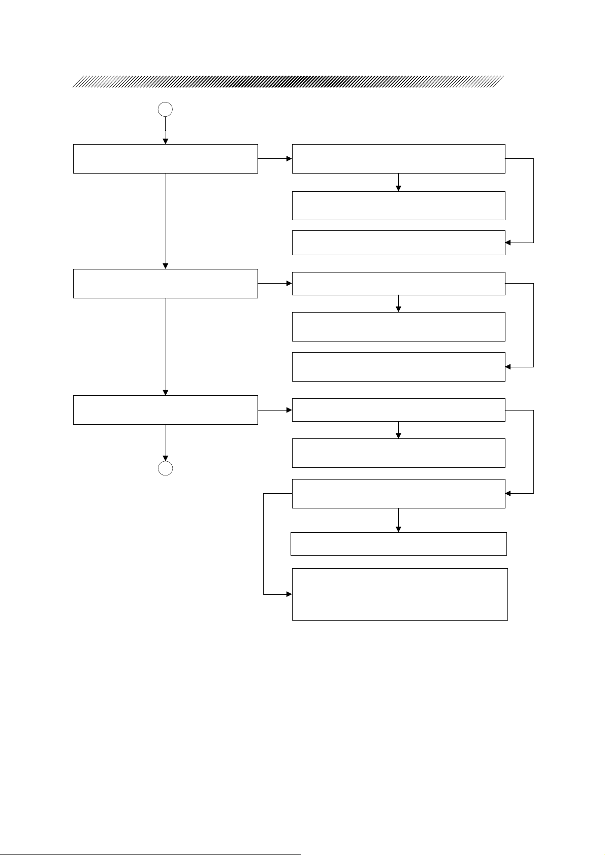
2
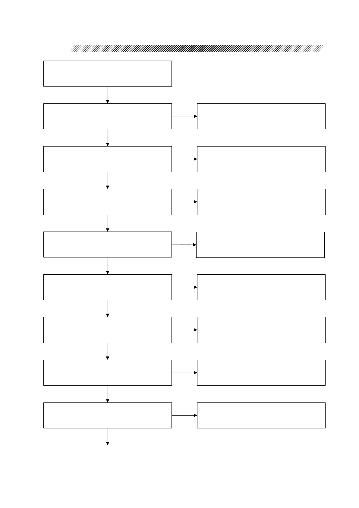
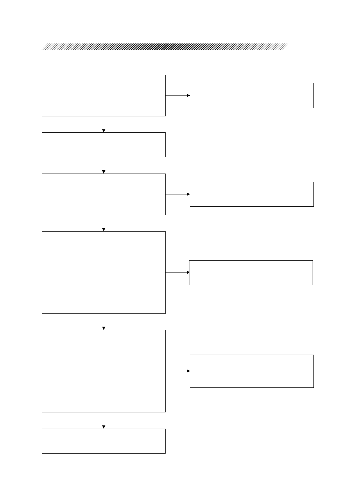
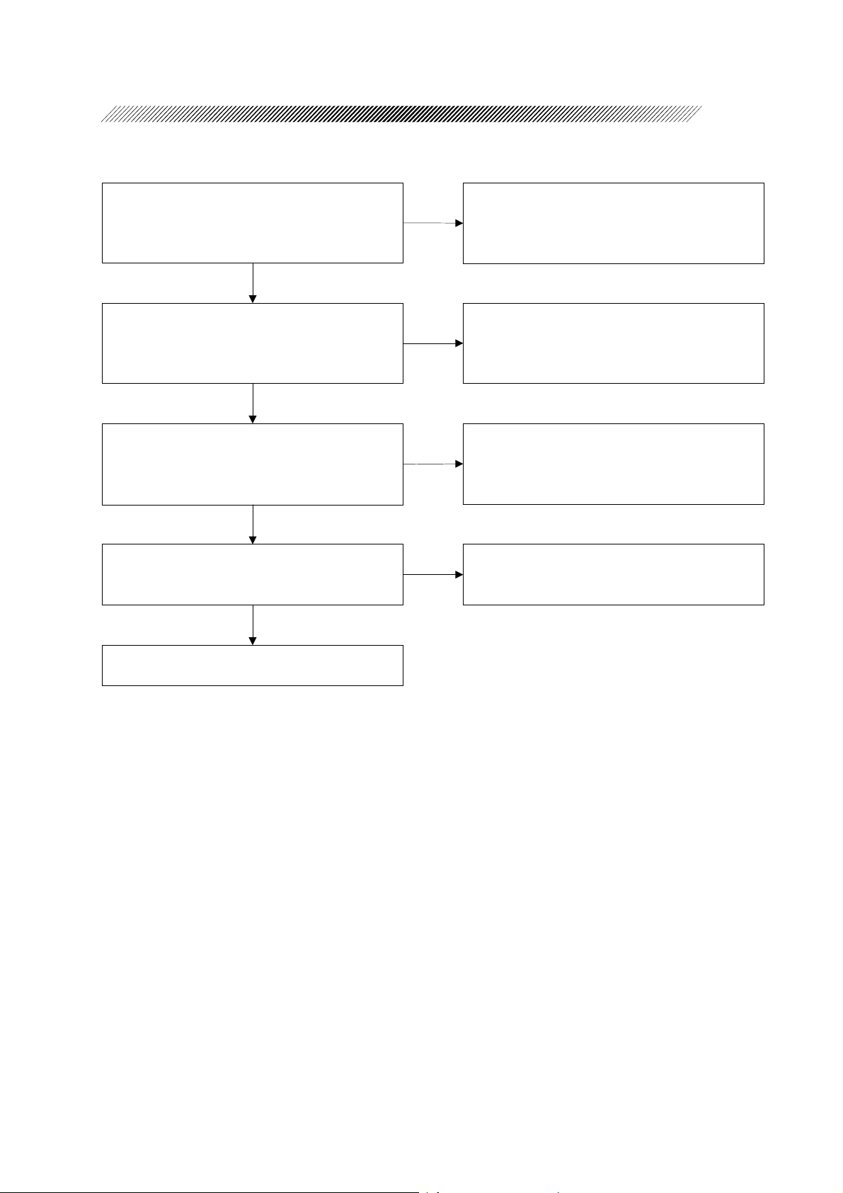
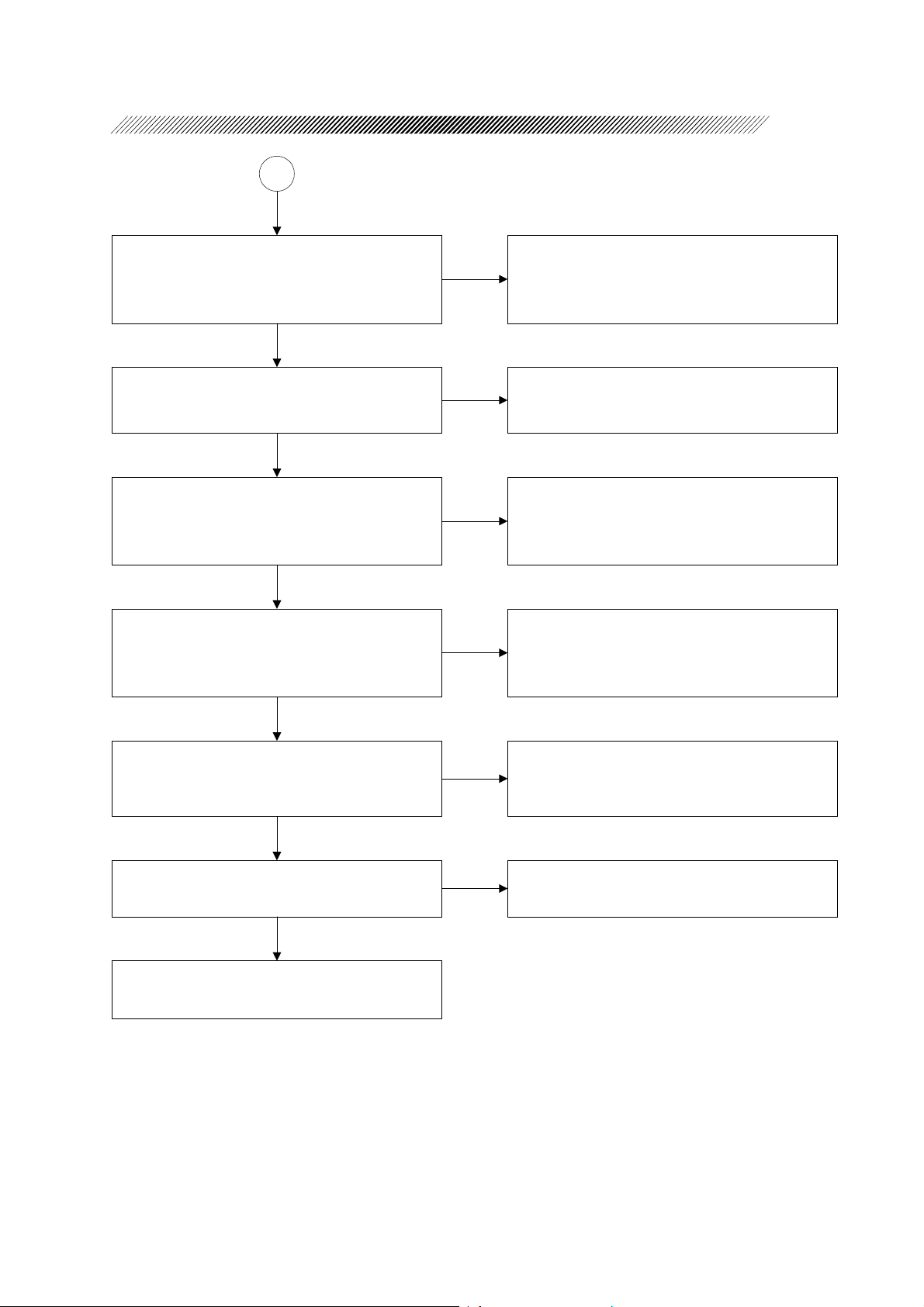
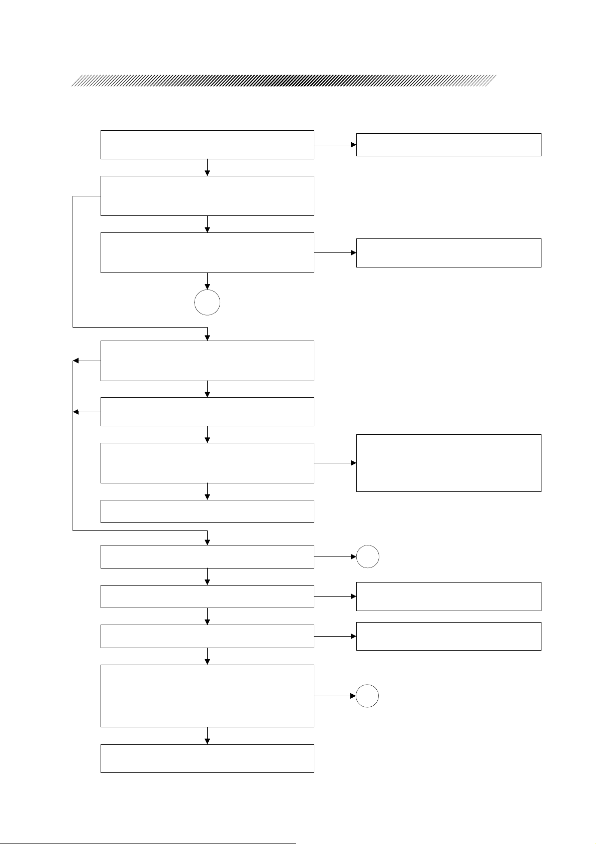
Turn ON the power.
TROUBLESHOOTING
Is an error indicated?
YES
Does the pilot lamp illuminate?
YES
Does an operation screen appear?
YES
Can the back light be adjusted by the knob on the
rear panel?
YES
Does the touch panel work?
NO
Check the indicated error.
NO
3.1 Pilot lamp does not illuminate
NO
3.2 Nothing appears on screen
NO
3.3 Back light can not be adjusted
NO
3.4 Touch panel does not work
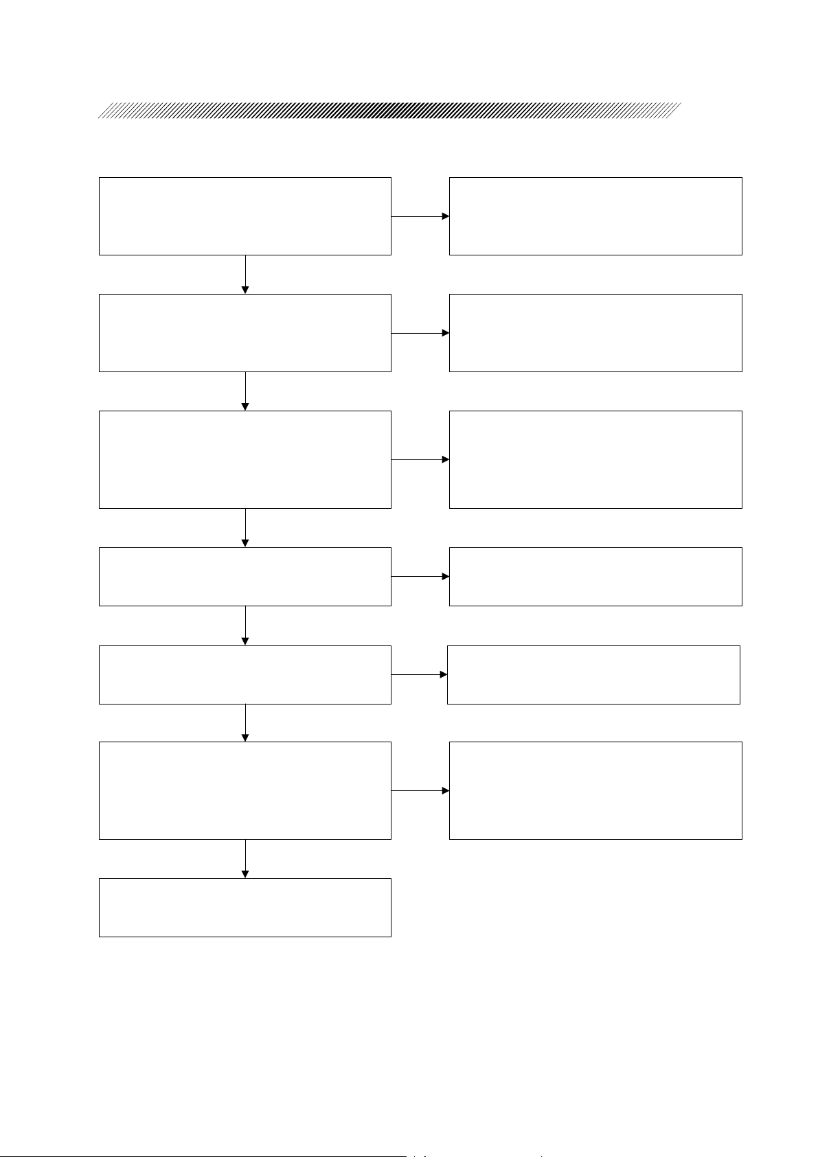
YES
Does the set switch work?
YES
Does the remote control work?
YES
Do sounds come out of speaker?
YES
NO
3.5 Seat switch does not work
NO
3.6 Remote control does not work
NO
3.7 Sounds do not come out
Page 8
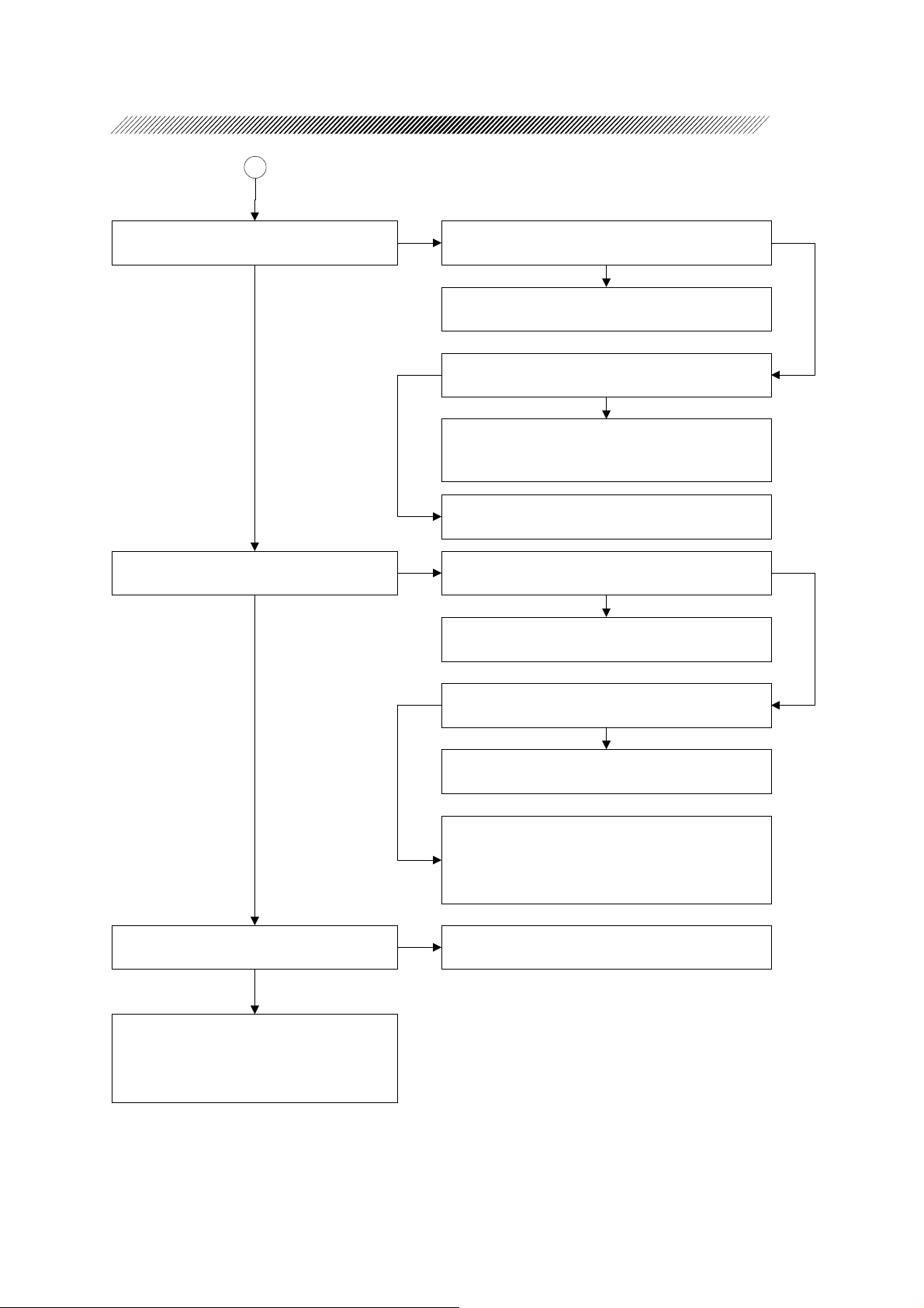
2 - 2
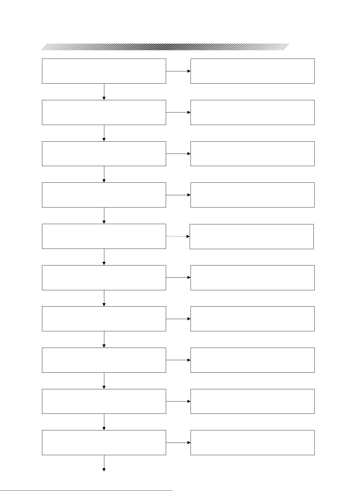
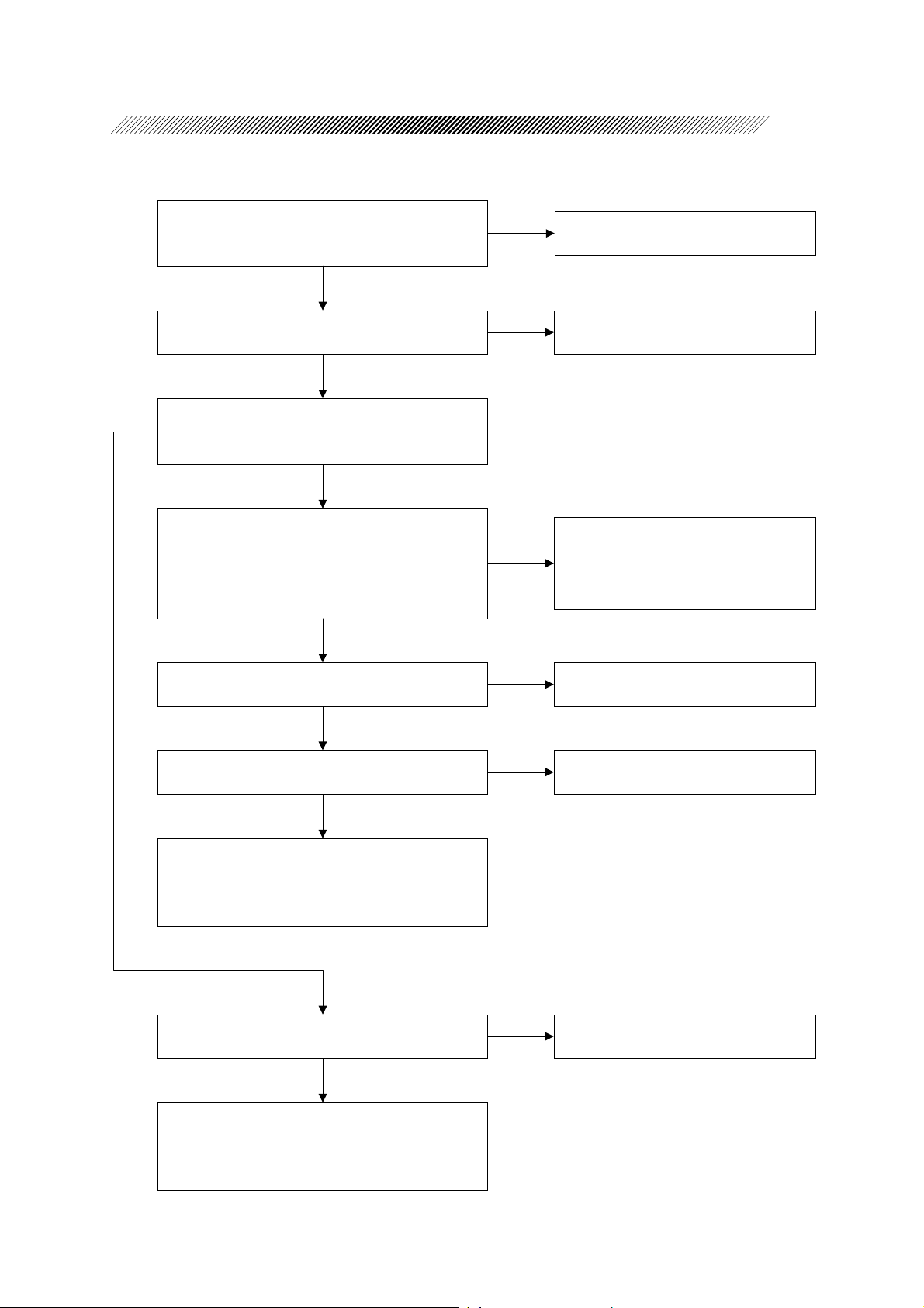
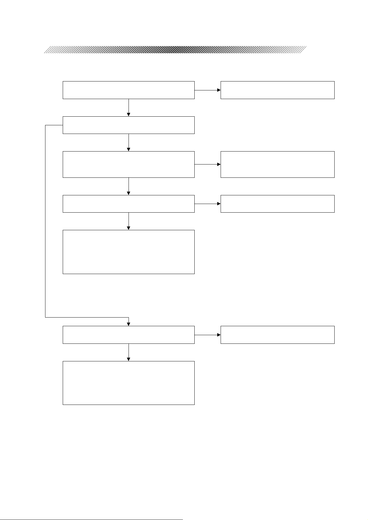
Can the volume of speaker be adjusted by the
volume control on the rear panel?
YES
Does the irrigation pole move by irrigation pole
UP/DOWN switch on the rear panel?
YES
Does the printer work normally?
YES
Is data stored or read to the main body correctly?
YES
Is data stored or read to memory card correctly?
NO
3.8 Volume can not be adjusted
NO
3.9 Irrigation pole does not move by irrigation
pole UP/DOWN switch
NO
3.10 Printer does not work normally
NO
3.11 Memory inside of main body does not work
correctly
NO
3.12 Memory card does not work correctly
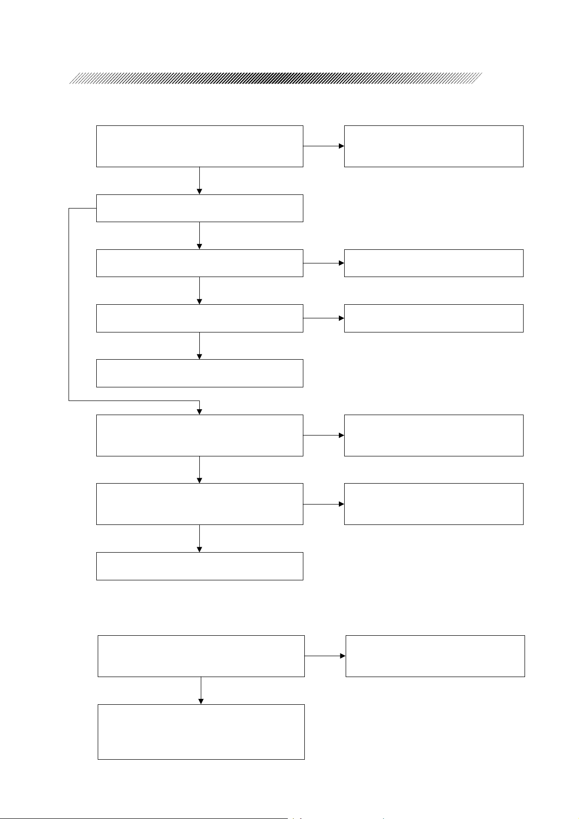
YES
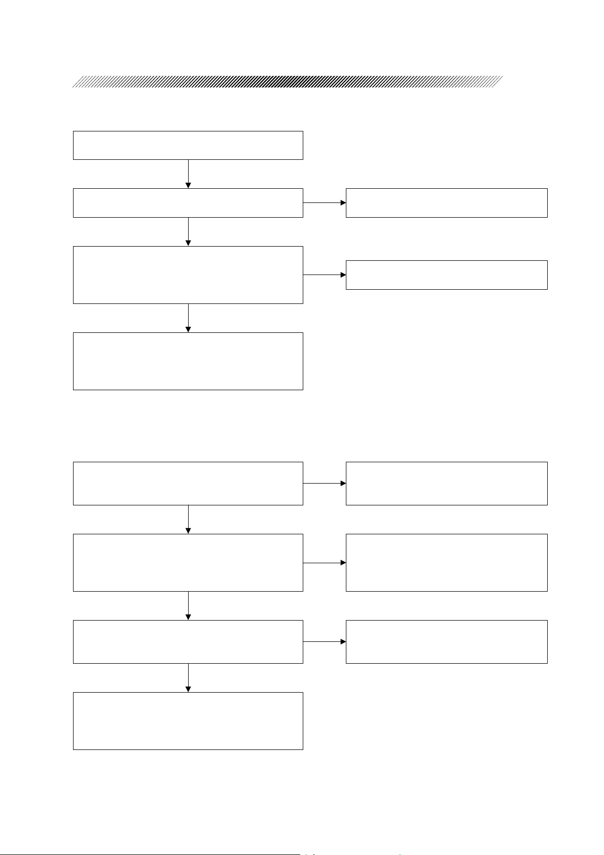
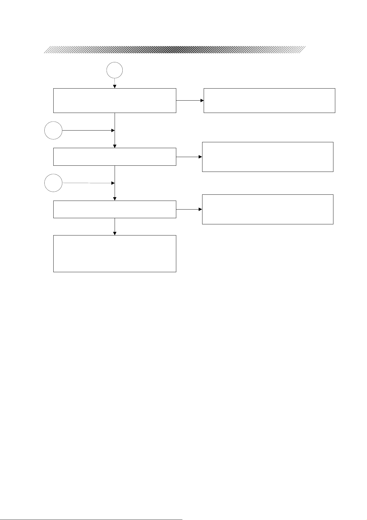
Does the system start a cassette test and pass it
by inserting cassette?
YES
Can the cassette be removed by EJECT switch
while the cassette is inserted?
YES
Start the SYSTEM (cataract) test.
Is it passed?
YES
Start the US test.
Is it passed?
YES
NO
3.13 Cassette test is not passed
NO
3.14 Cassette can not be removed
NO
3.15 SYSTEM (cataract) test is not passed
NO
3.16 US test is not passed
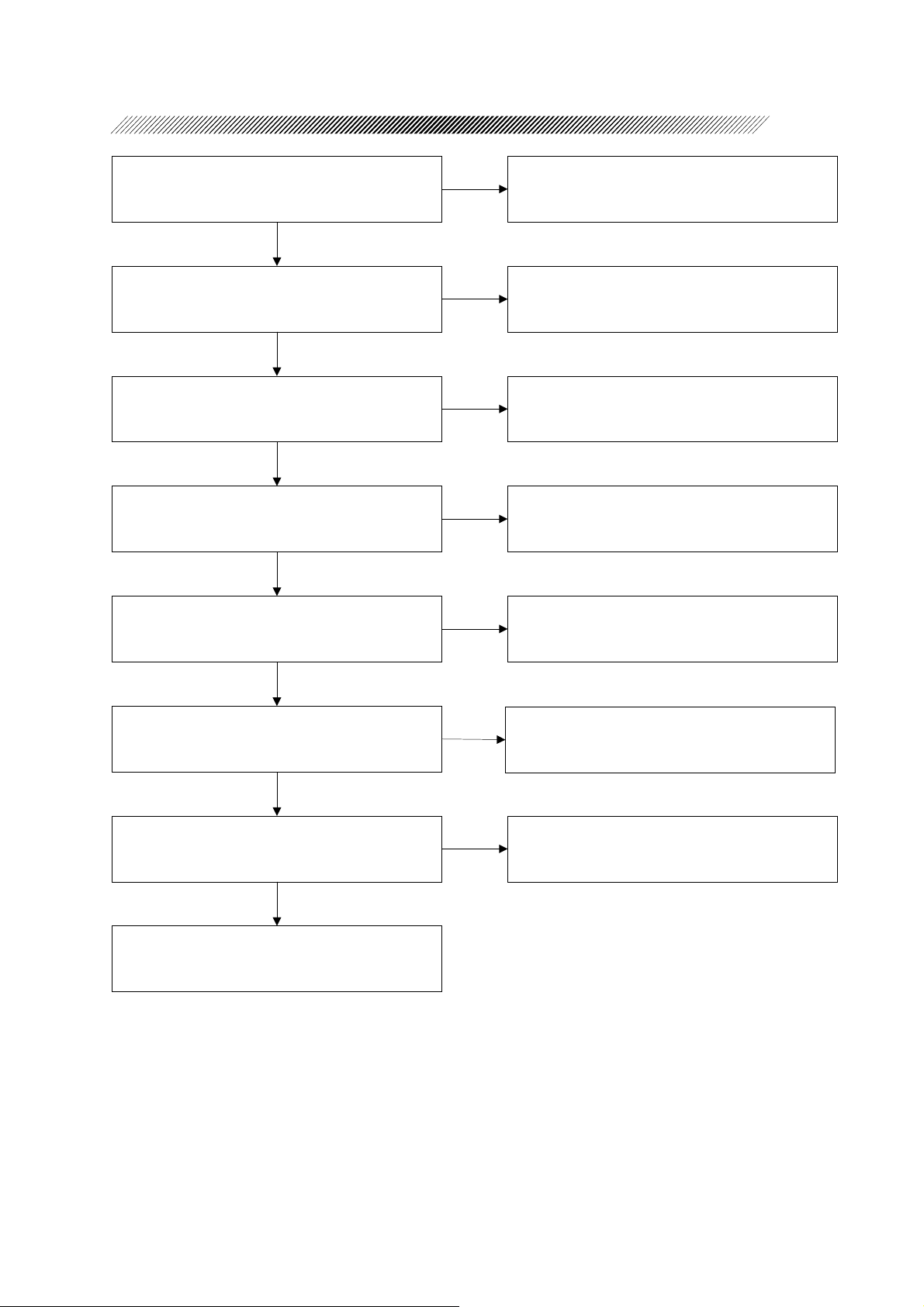
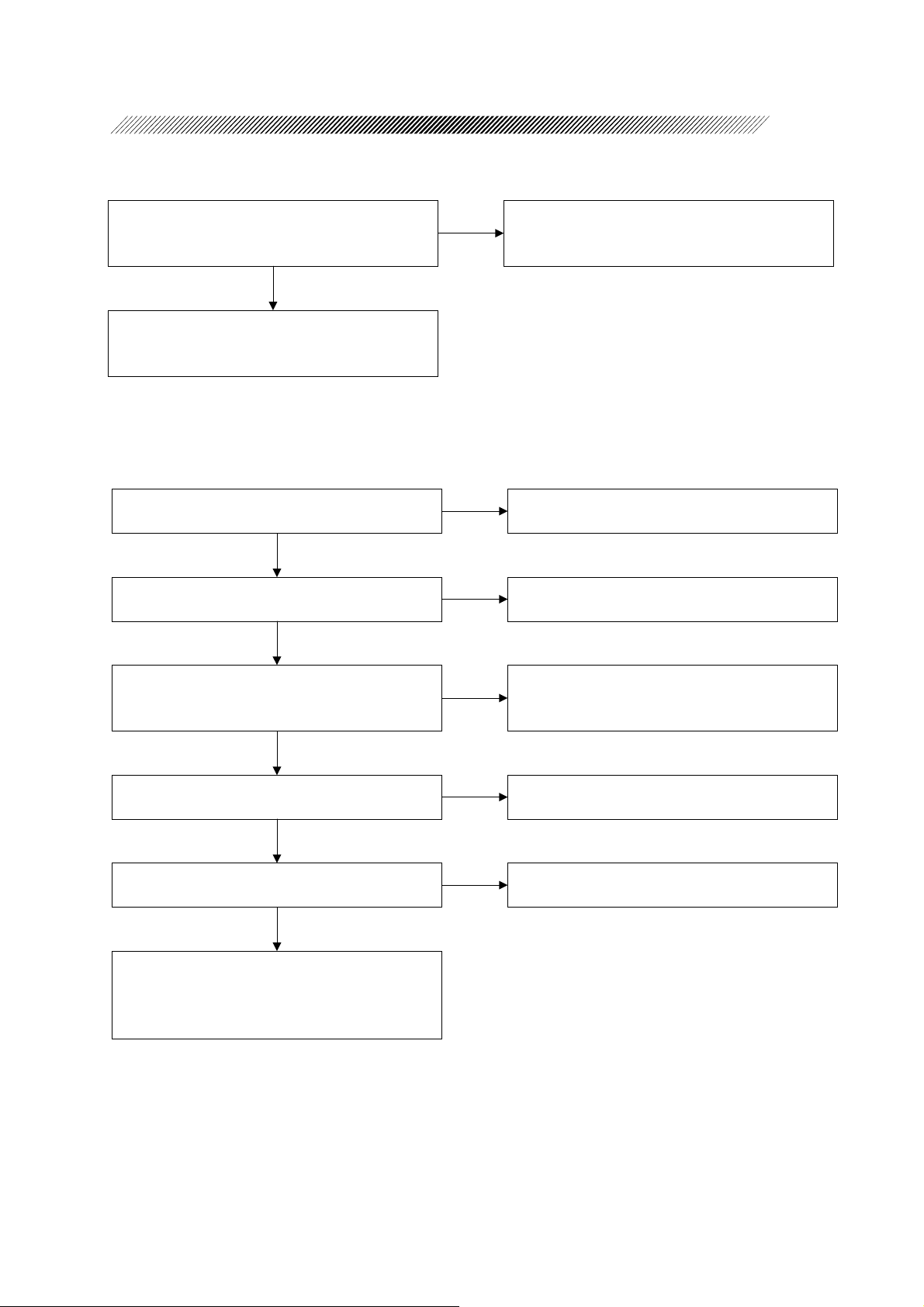
Start the DIA test.
Is it passed?
YES
NO
3.17 DIA test is not passed
Page 9

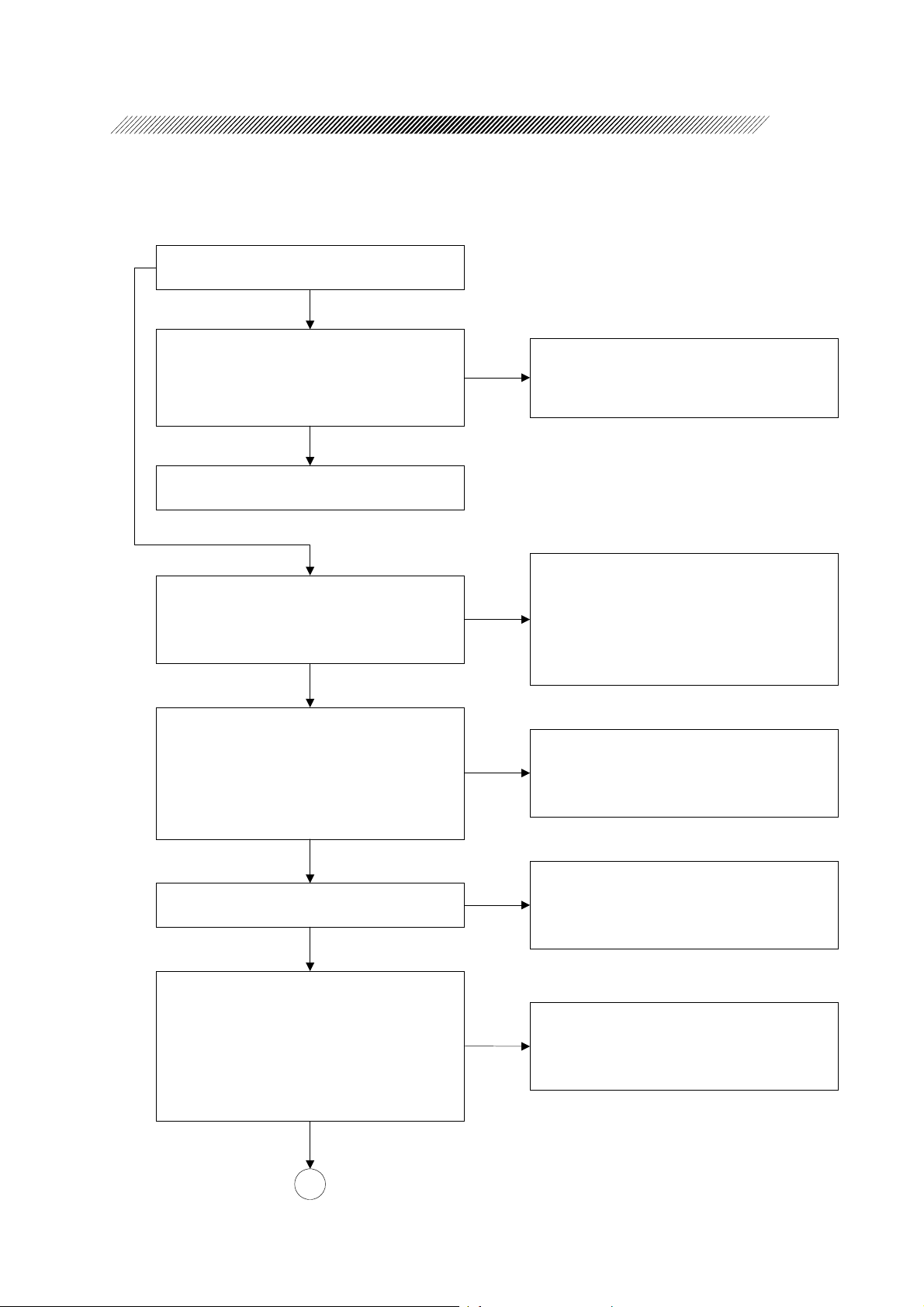
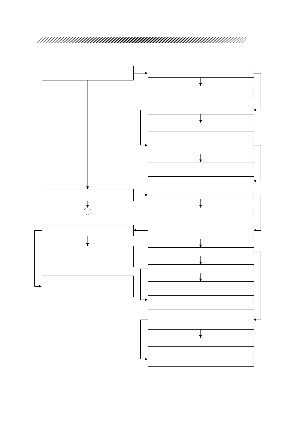
2 - 3
Does the foot switch work?
YES
Does the irrigation work correctly?
YES
Does the aspiration work correctly?
YES
Is US oscillation performed correctly?
YES
Is the diathermy output correctly?
NO
3.20 Foot switch does not work
NO
3.21 Irrigation does not move correctly
NO
3.22 Aspiration does not work correctly
NO
3.23 US oscillation is not performed correctly
NO
3.24 Diathermy output is abnormal
YES
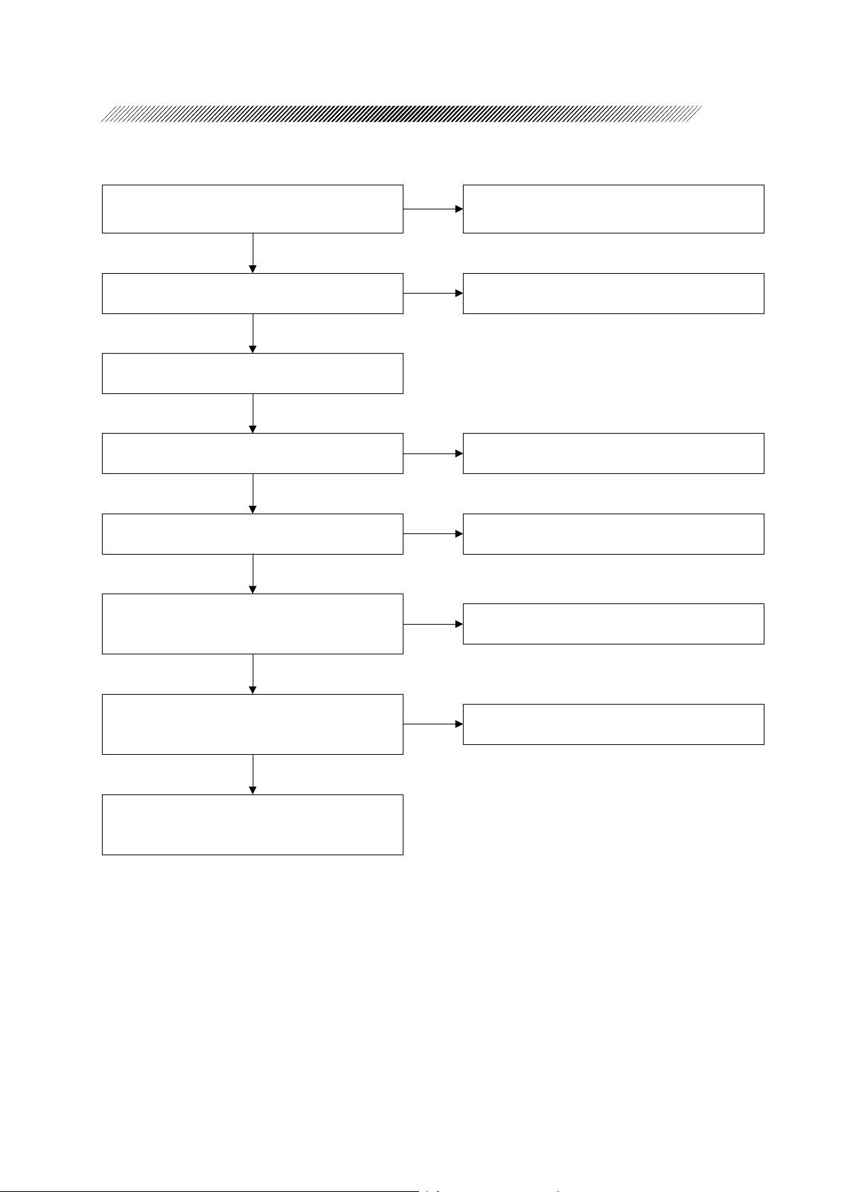
Does the cutter (ANT) work correctly?
YES
Is it a surgical instrument for cataract and
vitrectomy?
Surgical instrument for
cataract and vitrectomy
YES
Select vitrectomy surgery screen.
Start the SYSTEM (vitrectmy) test.
Is it passed?
YES
NO
3.25 Cutter (ANT) does not work
NO
Is the power correct?
YES NO
End
NO
3.18 SYSTEM (vitrectomy) test is not passed
3.30 Check of power (P.S.board)
Page 10
2 - 4
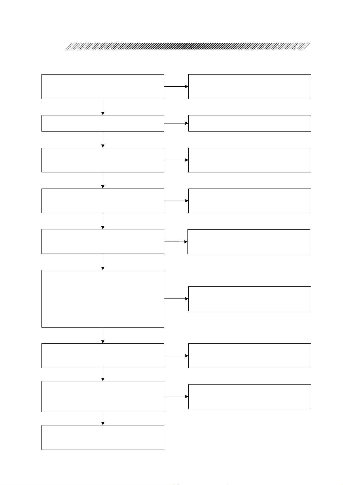
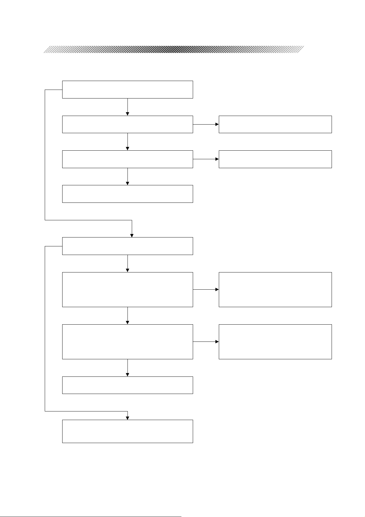
Start the PPL test.
Is it passed?
YES
Start the DIA test.
Is it passed?
YES
Does the cutter work correctly?
YES
Do scissors work correctly?
YES
Does FGX work correctly?
NO
3.19 PPL test is passed
NO
3.17 DIA test is passed
NO
3.26 Cutter (POST) does not work
NO
3.27 Scissors do not work correctly
NO
3.28 FGX does not work correctly
YES
Does the illumination work correctly?
YES
Is the power correct?
YES
End
NO
3.29 Illumination does not work correctly
NO
3.30 Check of the power (P.S. board)
Page 11
§
3
SUB-TROUBLESHOOTING
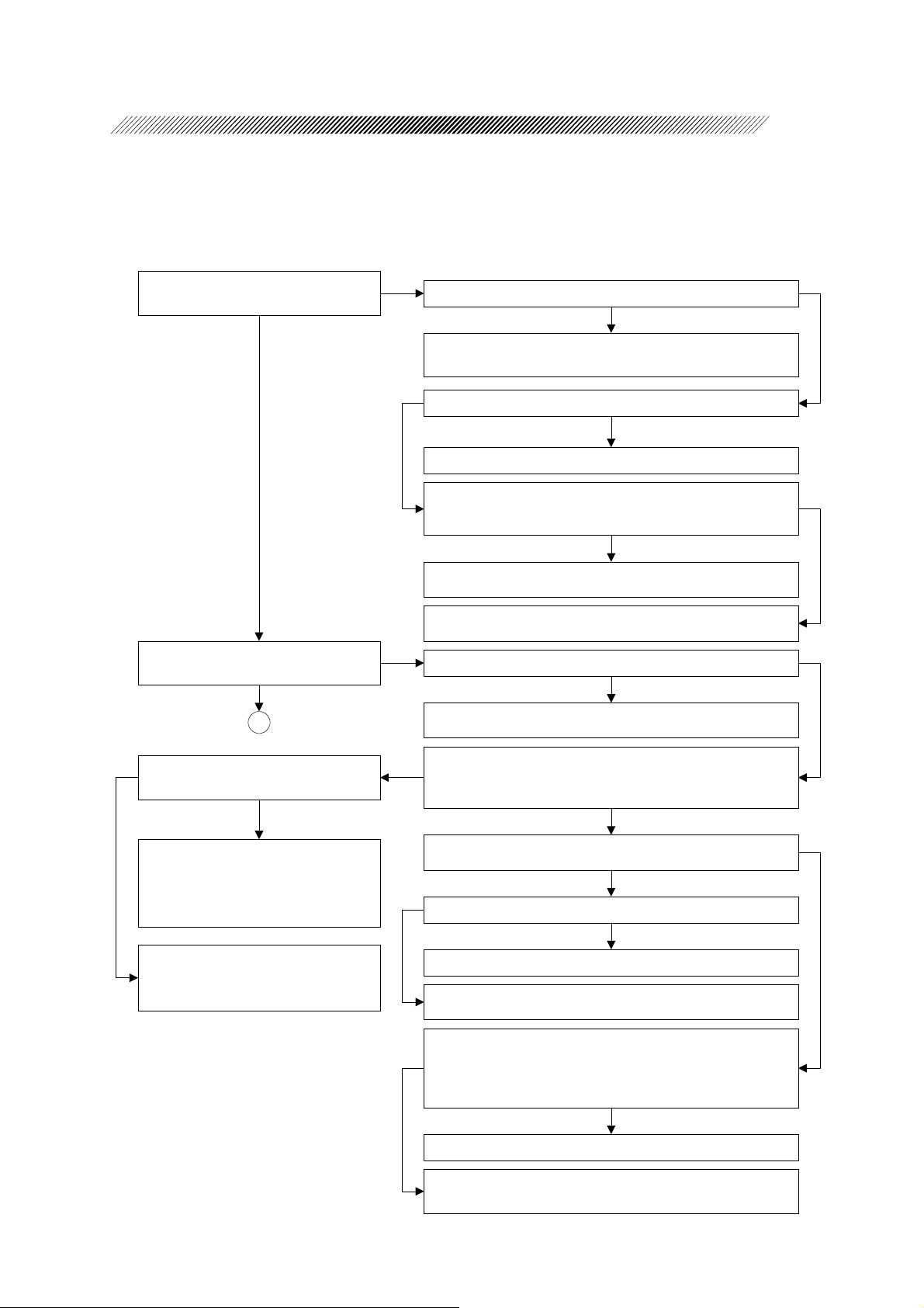
3.1 Pilot lamp does not illuminate
Is power voltage proper?
Voltage 100V/115V/230V
YES
Is the power code connected correctly?
YES
Is the fuse blown?
Disconnect the power cord from a wall outlet for
checking the fuse.
NO
Are voltages between the power input terminals
of the noise filter and the power switch (turned
OFF) same as the power voltage?
YES
Turn ON the power switch.
Is the power voltage supplied to the transformer?
(Check by TB1, a terminal block.)
NO
NO
YES
NO
NO
Use a proper power voltage.
Usable input voltage is written on the rating plate.
Connect the power cord.
Repalce the fuse with the new one.
Disconnect the power cord from a wall outlet for
checking the fuse.
Failure of the noise filter is a probable cause.
Replace it with the new one. (See 4.16.)
Replace the power switch with the new one.
(See 4.17.)
YES
Is the secondary side voltage of transformer
normal?
Check the secondary side voltage with no load.
Between YEL and YEL : AC33V±10%
Between ORN and ORN : AC33V±10%
Between BLK and BLU : AC100V±10%
Between GRY and BLU : AC66V±10%
Between VIO and BLU : AC33V±10%
YES
Is the voltage on the P.S. board (BA04) normal?
See 3.1.1 Check of P.S. board.
YES
Disconnect the P618 from the BU CONNECT
board (BA06).
Is the voltage between 1st and 2nd pins of J618
+5V?
YES
NO
Replace the transformer with the new one.
(See 4.18.)
NO
Replace the P.S. board (BA04) with the new one.
(See 4.12.)
NO
Failure of the BU CONNECT board (BA06).
Replace it with the new one. (See 4.19.)
Failure of the pilot lamp.
Replace it with the new one. (See 4.44.)
Page 12
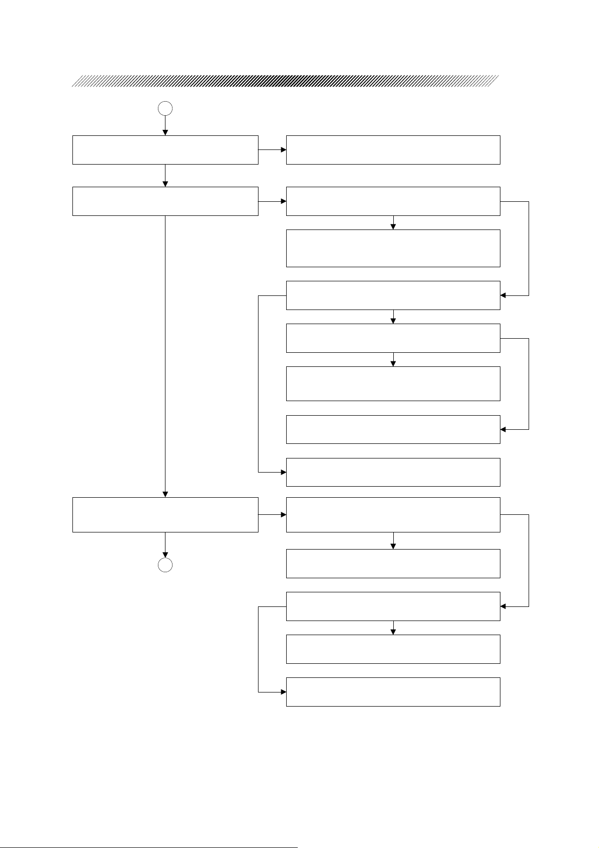
3.1.1 Check of P.S. board
Is the input voltage to the board normal?
Disconnect terminals from the terminal block
(TB401) on the board and check voltages.
Between YEL and YEL : AC35V±10%
Between ORN and ORN : AC35V±10%
YES
Connect terminals disconnected from the terminal
block (TB401).
Disconnect all connectors.
Is the input voltage to the board normal?
Check voltages of terminal block (TB401) on the
board.
Between 1 and 2 : AC35V±10%
Between 3 and 4 : AC35V±10%
Check the input voltage of transformer. If it is
NO
normal, replace the transformer with the new one.
(See 4.17.)
Failure of the P.S. board (BA04) is a probable
NO
cause. Replace the board with the new one.
(See 4.12.)
3 - 2
YES
Check voltages between GND and each TP while
connecting only TB401.
Is voltages on the P.S. board (BA04) normal?
TP2 : +12V (+11.5 ~ +12.5V)
TP3 : +28V (+27.5 ~ +29.0V)
TP4 : -28V (-27.5 ~ -29.0V)
TP6 : +12V (+11.9 ~ +12.1V)
TP7 : -12V (-11.9 ~ -12.1V)
TP8 : +6V (+5.0 ~ +6.0V)
TP9 : +5V (+4.8 ~ +5.2V)
TP10 : +24V (+22.0 ~ +26.0V)
YES
Connect all removed connectors and check
voltages between GND and each TP.
Is voltages on the P.S. board (BA04) normal?
TP2 : +12V (+11.5 ~ +12.5V)
TP3 : +28V (+27.5 ~ +29.0V)
TP4 : -28V (-27.5 ~ -29.0V)
TP6 : +12V (+11.9 ~ +12.1V)
TP7 : -12V (-11.9 ~ -12.1V)
TP8 : +6V (+5.0 ~ +6.0V)
TP9 : +5V (+4.8 ~ +5.2V)
TP10 : +24V (+22.0 ~ +26.0V)
NO
Failure of the P.S. board (BA04) is a probable
cause. Replace it with the new one. (See 4.12.)
Not only the failure of P.S. board (BA04) but
NO
other failures of board or unit are probable
causes.
Check other symptoms.
YES
The P.S. board (BA04) is normal.
Page 13
3.2 Nothing appears on screen
3 - 3
Does the irrigation pole move up and down by the
irrigation pole UP/DOWN switch on the rear
NO
3.2.1 Communication error of screen
panel?
YES
YES
Can the error beep be heard? 3.2.1 Communication error of screen
NO
Does the back light illuminate?
YES
The screen becomes black if the back light does
not illuminate.
NO
Disconnect the connector (P201) from the
DISPLAY board and check the voltage.
Is the voltage normal?
Between 1 and 2 (0V) of P201 : +5V
Between 3 and 4 (0V) of P201 : +12V
YES
NO
Failure of the power is a probable
cause.
Check the cable and the P.S. board.
(See 3.1.1 Check of P.S. board.)
Are J205 (DISPLAY board) and CN1 (inverter)
connected by a cable?
YES
Are CN2 and 3 of inverter connected to the LCD
back light?
YES
Failure of the LCD back light or the inverter.
Replace either of them with the new one.
(See 4.6.)
Is the cable between the LCD and the display
board connected?
YES
Failure of the LCD or the display board are
probable causes.
Replace either of them with the new one.
(See 4.7.)
NO
Connect them.
NO
Connect them.
NO
Connect them.
Page 14
3.2.1 Communication error of the screen
Turn OFF the dip switch (SW1) on the MAIN board
and turn ON the power again.
3 - 4
Is an error indicated? Check the indicated error.
NO
Is the flat cable connected to the main body
correctly?
MAIN board (P304) - DRIVER board (P502)
DRIVER board (P503) - DRIVER board (P202)
YES
Failure of the MAIN board or the DISPLAY board are
probable causes.
Replace either of them with the new one.
(See 4.7 and 4.8.)
YES
NO
Connect the flat cable correctly.
3.3 Back light can not be adjusted
Does the brightness of back light change by turning
the back light control knob on the rear panel?
YES
Normal
NO
Does the voltage of TP7 (BACKLIGHT) change by
turning the back light control knob?
YES
Does the voltage of TP9 change by turning the back
light control knob?
YES
Failure of the inverter or the LCD back light are
probable causes.
Replace either of them with the new one. (See 4.6.)
Failure of cables among back light control
NO
volume, the VR board and the DISPLAY board.
Replace the VR board or the cable with the
new one.
NO
Failure of the DISPLAY board.
Replace it with the new one. (See 4.7.)
Page 15
3.4 Touch panel does not work
3 - 5
Does the touch panel work normally?
Is there no torn, worn or dented part on the
NO
Replace the LCD unit with the new one.
surface?
YES
NO
Is PJ204 connected correctly? Connect it correctly.
YES
Turn OFF the power to check.
NO
Is the resistance between TP2 and 3 several kΩ?
YES
Is the resistance between TP5 and 6 several kΩ?
YES
Failure of the touch panel is a probable cause.
Replace the LCD unit with the new one.
NO
Failure of the touch panel is a probable cause.
Replace the LCD unit with the new one.
Is the resistance between TP1 and 6 more than
10 kΩ? Does it change to several kΩ by pressing
the touch panel?
YES
Is the resistance between TP3 and 4 more than
10 kΩ? Does it change to several kΩ by pressing
the touch panel?
YES
The touch panel is probably normal.
Replace the DISPLAY board with the new one.
(See 4.7.)
NO
Failure of the touch panel is a probable cause.
Replace the LCD unit with the new one.
NO
Failure of the touch panel is a probable cause.
Replace the LCD unit with the new one.
Page 16
3.5 Seat switch does not work
NO
Does the touch panel work?
YES
3 - 6
Failure of the DISPLAY board or other units.
Replace the DISPLAY board or check other items.
(See 4.7.)
Does a mode change or the beep sound by
operating the switch on the seat switch?
If a volume is at low level, the beep can not be
heard.
NO
Is the connection terminal of seat switch
connected to the connector (J206) on the
DISPLAY board?
YES
Replace the seat switch with the new one.
Is it possible to operate by the seat switch?
YES
The cause was failure of the seat switch.
YES
NO
NO
Normal.
Refer to the operator's manual and check the
operating procedures.
Connect the terminal of seat switch to the
connector.
Failure of the DISPLAY board.
Replace it with the new one. (See 4.7.)
Page 17
3.6 Remote control does not work
Failure of DISPLAY board or the other units.
NO
Does the touch panel work?
YES
Is the power of remote control turned ON by
pressing the power switch of remote control?
YES
Are codes of remote control and RC of the main
body same?
Replace the DISPLAY board or check the other
items. (See 4.7.)
Replace batteries of remote control with the new
NO
one.
If the power is not turned ON even replacing
batteries, it shows failure of remote control itself.
Use a same cord for remote control and RC of the
main body.
NO
The cord for remote control is set by the dip
switch in batteries of remote control. The cord
for the main body is set on the CUSTOM screen.
3 - 7
YES
Are there any other infrared light on the
photoreceptor of the display unit?
NO
Is the cable of RECEIVER board connected to
J210 on the DISPLAY board?
YES
Connect the photoreceptive signal between R5
and R6 on the DISPLAY board to the oscilloscope.
Does the photoreceptor receive remote control
signal and input the signal to the oscilloscope?
YES
Failure of the DISPLAY board.
Replace it with the new one. (See 4.7.)
YES
NO
NO
Eliminate the infrared light.
Connect the cable.
Failure of the remote control or the RECEIVER
board on the display unit are probable causes.
Replace either of them with the new one.
(See 4.21.)
Page 18
3.7 Sounds do not come out
3 - 8
Is the volume control knob at proper position?
No sounds can be heard if the knob is turned to
the lowest level.
YES
YES
Can the beep sound be heard by pressing
switches?
NO
Is the cable from speaker connected to J308 on
the MAIN board?
YES
Is the resistance between 1st and 2nd pins of
P308 connector of speaker 7 to 8Ω?
YES
Failure of the MAIN board.
Replace it with the new one. (See 4.8.)
NO
Turn the volume control knob to proper
position.
NO
Connect the cable.
NO
Failure of speaker.
Replace it with the new one. (See 4.22.)
Is sound output set ON?
Check the sound output setting by VOICE on the
CUSTOM screen.
YES
Input sound data from the sound card on the
service screen. Do sounds become normal?
YES
End
3.8 Volume can not be adjusted
Does the voltage of TP8 (VOLUME) on the
DISPLAY board change by turning the volume
control knob?
YES
NO
Set the sound setting to ON.
NO
Failure of the MAIN board. (See 4.8.)
NO
Failure of the VR board.
Replace it with the new one. (See 4.20.)
Failure of the volume control circuit on the MAIN
board is a probable cause.
Replace the MAIN board with the new one.
(See 4.8.)
Page 19
3 - 9
3.9 Irrigation pole does not move by irrigation UP/DOWN
switch
NO
Does the irrigation pole move up and down by
the LCD touch panel?
YES
Disconnect P310 from the MAIN board and
check switch operation.
Is switch contact turned ON or OFF correctly
by operating the irrigation pole UP/DOWN
switch?
YES
Failure of the MAIN board.
Replace it with the new one.
Is the limit switch (micro switch) on the upper
side or the lower side of the irrigation pole
turned ON?
NO
NO
YES
Failure of the irrigation pole UP/DOWN switch.
Replace it with the new one. (See 4.23.)
The irrigation pole does not move since it
comes to the limit position.
Check the limit switch or adjust the pole
position. (See 4.9.) Moreover, the pole can
not move since the upper side or lower side of
the irrigation pole is bitten in some cases.
Is the signal of limit switch of the irrigation
pole turned ON?
MAIN board
UP LIMIT SW:IC20-2 pin 0V=ON, 5V=OFF
DOWN LIMIT SW :IC20-3 pin 0V=ON, 5V=OFF
NO
Is the indication of irrigation height within the
working range?
YES
Is the control signal output by pressing the
irrigation pole UP/DOWN switch?
MAIN board
UP SW :IC21-19 pin 0V=ON、5V=OFF
DOWN SW :IC20-18 pin 0V=ON、5V=OFF
BU CONNECT board
UP SW :IC2-12 pin 0V=ON、12V=OFF
DOWN SW :IC2-11 pin 0V=ON、12V=OFF
YES
A
YES
NO
NO
Failure of the limit switch is a probable cause.
Check the limit switch or the signal line.
The irrigation pole moves up and down only
within the working range.
Ajdust the potentiometer if the height position
is not correct. (See 5.10.)
Failure of the MAIN board or the BU
CONNECT board are probable causes.
Replace the board with the new one.
(See 4.8. and 4.19.)
Page 20
3 - 10
A
Is AC100V supplied to the POLE CONTROL
board?
Check the voltage between 1st and 3rd pins of
P712 is AC100V.
YES
Is the connector on the POLE CONTROL board
connected correctly?
YES
Press the irrigation pole UP switch.
Is the relay (RY1) on the POLE CONTROL board
turned ON? Is the AC100V supplied between 1st
and 4th pins of J706 connector?
YES
Press the irrigation pole DOWN switch.
Is the relay (RY2) on the POLE CONTROL board
turned ON? Is the AC100V supplied between 2nd
and 4th pins of J706 connector?
NO
NO
NO
NO
The transformer or the input power is abnormal.
Check the input power or replace the transformer
with the new one. (See 4.18.)
Connect it correctly.
Failure of the POLE CONTROL board is a
probable cause.
Replace the board with the new one. (See 4.25.)
Failure of the POLE CONTROL board is a
probable cause.
Replace the board with the new one. (See 4.25.)
YES
Does the AC motor rotate by pressing the
irrigation pole UP/DOWN switch?
YES
Does the irrigation pole move up and down if the
AC motor for the irrigation pole rotate?
YES
Normal.
Failure of the AC motor.
NO
Replace the AC motor or the condenser for motor
(C1) with the new one. (See 4.10 and 4.36.)
The gear or the belt of the motor may be
NO
abnormal.
Check them.
Page 21
3.10 Printer does not work normally
3 - 11
Is paper loaded to the printer? Load paper to the printer.
NO
YES
YES
Is it possible to print by the PRINT switch on the
rear panel?
NO
Is it possible to print by the PRINT switch on the
touch panel?
NO
Is the connector on the MAIN board (J312)
connected correctly?
YES
YES
NO
Replace the PRINT/FEED switch (BA29) or
the cable (EA41) with the new one.
(See 4.24.)
Connect it.
Failure of the printer, the board (BA08) or the
MAIN board are probable causes.
Replace the printer or the board with the new
one. If the symptom is not solved, replace the
MAIN board with the new one. (See 4.8. and 4.14.)
Are date and time printed correctly?
YES
Failure of the printer, the board (BA08) or the
MAIN board are probable causes.
Replace the printer or the board with the new
one. If the symptom is not solved, replace the
MAIN board with the new one. (See 4.8 and 4.14.)
NO
Set time on the CUSTOM screen.
Page 22
3 - 12
3.11 Memory inside of main body does not work correctly
Is the Store switch pressed to store the contents
of program?
YES
Failure of the MAIN board or the flash memory are
probable causes. Replace the board with the new
one. (See 4.8.)
NO
Press the Store switch to store the program to
the flash memory.
3.12 Memory card does not work correctly
Is the memory card for programming inserted? Insert the memory card for programming.
YES
Does the memory card operation screen appear
by pressing the memory card switch?
YES
NO
NO
The memory card is not recognised for use in
programming. Check the memory card.
Is it possible to write to the memory card?
YES
Replace the memory card with the new one.
Does it work normally?
NO
Is the cable between the MAIN board and the
CARD board connected correctly?
YES
Failure of the MAIN board (BA03) or the CARD
board (BA24) are probable causes. Replace the
board with the new one. (See 4.8 and 4.38.)
NO
YES
NO
The memory card may be protected.
Unprotect the card.
Breakage of the memory card is a probable cause.
Connect it correctly.
Page 23
3.13 Cassette test is not passed
NO
Insert the cassette. Does the cassette loading
start?
YES
3 - 13
Replace the cassette with the new one. Is the
cassette test passed?
NO
Does an error occur when the cassette test is
finished?
NO
Normal
YES
Does the screen change to the cassette test by
inserting the cassette?
NO
Is the continuity between 1st and 2nd pins of
P515 connected to the DRIVER board turned ON
from OFF by inserting the cassette?
YES
YES
NO
Failure of the cassette is a probable cause.
Check the cause of error from the error
code.
Failure of the microswitch (SW56) is a
probable cause.
Replace it or check soldering. (See 4.26.)
YES
Is the continuity between 1st and 2nd pins of
P516 connected to the DRIVER board turned ON
from OFF by inserting the cassette?
YES
Failure of the DRIVER board is a probable cause.
Replace it with the new one. (See 4.29.)
Failure of the DRIVER board is a probable cause.
Replace the board with the new one. (See 4.29.)
NO
Failure of the microswitch (SW58) is a
probable cause.
Replace it or check soldering. (See 4.26.)
Page 24
3.14 Cassette can not be removed
3 - 14
YES
Is the continuity of the cable between the
DRIVER board and the EJECT switch normal?
YES
Does the 3rd pin of IC3 on the DRIVER board
change from 5V to 0V by pressing the EJECT
switch?
NO
Disconnect the P524. Does the continuity
between 5th and 7th pins of P524 change by
pressing the EJECT switch?
YES
B
Does the CASSETTE EJECT LED change from
YES
lighting up to blinking by pressing the EJECT
siwtch?
NO
YES
Is the state of the poistion O indicated while the
foot switch is not pressed on the screen?
NO
NO
Replace or repair the cable.
NO
Replace the board of the EJECT switch
with the new one. (See 4.27.)
Disconnect the connector of the foot switch and
press the EJECT switch. Is it possible to remove
the cassette?
YES
Failure of the foot switch.
Does the DC motor of EA38 rotate?
YES
Does the cassette move down?
YES
Are all pinch valves turned up?
NO
Do pinch valves move by replacing the unmoving
valves?
If there is no pinch valve to replace, connect to
the connector of other pinch valve and check the
operation.
YES
NO
NO
NO
YES
NO
Failure of the cable and the board (BU
CONNECT board) between the foot switch
connector and the MAIN board. (See 4.19.)
A
Replace the control unit (18214-1130) with
the new one. (See 4.11.)
Replace the control unit (18214-1130) with
the new one. (See 4.11.)
C
Replace the pinch valve with the new one.
(See 4.39.)
Page 25
3 - 15
A
Does the 24V of voltage occur between 1st
and 2nd pins of J513 while ejecting the
cassette by the EJECT switch?
C
NO
Is DC 24V supplied to the 7th pin of P501?
B
YES
Is DC 5V supplied to the 1st pin of P501?
YES
Failure of the DRIVER board, the MAIN board
or the cable between boards.
Replace either of them with the new one.
(See 4.8 and 4.29.)
YES
Failure of the DC motor (EA38) or the loading
mechanism. Replace the control unit (18214-
1130) with the new one. (See 4.11.)
Failure of the power cable (EA34) to the DRIVER
NO
board, or the power. Replace the cable with the
new one or check the power following the item of
power. (See 3.30.)
Failure of the power cable (EA34) to the DRIVER
NO
board, or the power. Replace the cable with the
new one or check the power following the item of
power. (See 3.30.)
Page 26
3.15 SYSTEM (cataract) test is not passed
3.15.1 SINGLE CASSETTE
3 - 16
Does the ERROR CODE E200 No.17
appear on the screen?
NO
Does the ERROR CODE E200 No.31
appear on the screen?
NO
A
YES
Is the connection set removed during a test?
YES
Eject the cassette once. Start SYSTEM TEST again
after connecting the connection set.
YES
Are each conductors of EA44 continuous?
NO
Replace the EA44 with the new one.
Shade the each photointerrupters of BA28. Do the 2nd,
3rd and 4th pins of IC4 on the DRIVER board (BA05)
change ON or OFF?
NO
Replace the TUBE SENS board (BA28) with the new one.
(See 4.28.)
Replace the DRIVER board (BA05) with the new one.
(See 4.29.)
YES
Does the ERROR CODE E307 appear simultaneously?
YES
Failure of EA39 or the DRIVER board (BA05).
(See 4.29.)
NO
YES
NO
YES
Does the aspiration motor rotate
while all pinch valves are closed?
NO
Failure of the pinch valve. Check
the pinch valve following the item of
irrigation and aspiration.
(See 3.21 and 3.22.)
An air leakage of the cassette is a
probable cause. Replace the
cassette with the new one.
Select a mode on the service mode. Does the aspiration
YES
pressure change by pressing the aspiration sensor with a
hand?
NO
Is DC5V supplied to the 1st pin of J262 on the VACUUM
SENS board (BA26)? (See 4.37.)
NO
YES
Are each conductors of EA46 continuous?
NO
Failure of EA46.
Failure of the VACUUM SENS board (BA26).
(See 4.37.)
Select a mode in the service mode while the cassette is
YES
not inserted and press the load cell with a hand. Does
the voltage of TP1 on the VACUUM SENS board (BA26)
change?
NO
Failure of the EA31. Replace it with the new one.
Failure of the VACUUM SENS board (BA26) or EA31.
Replace or readjust either of them. (See 4.37 and 5.11.)
YES
Page 27
3 - 17
A
Does the ERROR CODE E200 No.32 appear
on the screen?
NO
Does the ERROR CODE E200 No.33 appear
on the screen?
NO
YES
An air leakage of the cassette is a probable
cause. Replace the cassette with the new one.
YES
Does the VENT VALVE work?
NO
Failure of the pinch valve. Check the pinch valve
following the item of irrigation and aspiration.
(See 3.21 and 3.22.)
YES
Is the flow rate control of transfusion tube
closed?
NO
Is the opening for air intake of spike of transfusion
tube closed?
YES
Open the opening for air intake or insert the
needle. And then, perform SYSTEM TEST again.
The cassette is probably clogged. Replace the
cassette with the new one.
YES
NO
Does the ERROR CODE E200 No.34 appear
on the screen?
NO
B
Open the flow rate control and perform SYSTEM
TEST again.
Are the aspiration line, the irrigation line,
YES
handpiece and the test chamber connected
securely?
NO
Connect the aspiration line, the irrigation line,
handpiece and the test chamber securely.
YES
Does the IRR1 valve work normally?
NO
Check the pinch valve following the item of
irrigation. (See 3.21.)
The cassette is probably clogged. Replace the
cassette with the new one.
YES
Page 28
3 - 18
B
YES
Does ERROR CODE E200 No.35 appear? Does the ASP1 valve work normally?
NO
NO
Check the pinch valve following the item of
aspiration. (See 3.22.)
The cassette or handpiece is probably clogged.
YES
Does ERROR CODE E200 No.36 appear?
NO
Is the connection set inserted securely?
NO
Insert the connection set securely and perform
SYSTEM TEST again.
An air leakage of cassette is a probable cause.
Replace the cassette with the new one.
YES
Does ERROR CODE E200 No.42 appear?
NO
Does the cassette loader work?
NO
Check the control unit following the item that
cassette can not be removed. (See 3.14.)
C
YES
Are each conductors of EA44 continuous
securely?
YES
YES
YES
NO
Replace the EA44 with the new one.
Failure of the CASSETTE SENS board (BA27) or
the adjustment failure of the control unit.
Replace the control unit or BA27, and readjust
the replaced one. (See 4.11, 4.30 and 5.11.)
Page 29
3 - 19
C
Does the ERROR CODE E200 No.43
appear?
NO
Does the ERROR CODE E200 No.44
appear?
NO
YES
Does the drainage bag come to the limit?
YES
Replace the cassette with the new one.
NO
Is the problem solved by replacing the cassette?
YES
Failure of the cassette. Readjust the control unit
if the error frequently occurs. (See 4.11.)
Readjust the control unit. (See 5.11.)
YES
Does the cassette loader work?
NO
Check the control unit following the item that
cassette can not be removed. (See 3.14.)
NO
YES
Does the ERROR CODE E210 appear?
NO
If the switch of SYSTEM TEST can not be
pressed, it means occurrence of an error.
Follow the indicated error code to solve it.
YES
Are each conductors of EA44 continuous
securely?
NO
Replace the EA44 with the new one.
Failure of the CASSETTE SENS board (BA27) or
adjustment failure of the control unit. Replace
the control unit or BA27, and readjust the
replaced one. (See 4.11, 4.30 and 5.11.)
YES
Check the ultrasound oscillation part following the
item of TEST US.
Page 30
3.15.2 ANT DUAL CASSETTE
3 - 20
Does the ERROR CODE E200 No.17
appear?
NO
Does the ERROR CODE E200 No.31
appear?
NO
A
YES
Is the connection set removed during TEST?
YES
Eject the cassette once. Perform SYSTEM TEST
again while connecting the connecting set.
YES
Are the each conductors of EA44 continuous?
NO
Replace EA44 with the new one.
Shade the each photointerrupters of BA28. Does
the 2nd, 3rd and 4th pins of IC4 of BA05 change
to ON or OFF?
NO
Replace BA28 with the new one. (See 4.28.)
Replace BA05 with the new one. (See 4.29.)
YES
Does ERROR CODE E307 appear simultaneously?
YES
Failure of EA39 or BA05. (See 4.29.)
NO
YES
NO
YES
Does the aspiration motor rotate while the
pinch valve is fully opened?
NO
Failure of the pinch valve. Check the pinch
valve following the item of irrigation and
aspiration. (See 3.21 or 3.22.)
An air leakage of the cassette is a probable
cause. Replace the cassette with the new
one.
Select a mode in the service mode and press the
YES
aspiration sensor with a hand. Does the
aspiration pressure change?
NO
Is DC5V supplied to the 1st of J262 of BA26?
NO
YES
Are each conductors of EA46 continuous?
NO
Failure of EA46.
Failure of BA26. (See 4.37.)
Select a mode without inserting a cassette and
YES
press the load cell with a hand. Does the voltage
of TP1 of BA26 change?
NO
Failure of EA31. Replace it with the new one.
Failure of BA26 or EA31. Replace or readjust
either of them (See 4.37 and 5.11.)
YES
Page 31

A
YES
Does ERROR CODE E200 No.32 appear?
NO
An air leakage of the cassette is a probable
cause. Replace the cassette with the new one.
YES
Does ERROR CODE E200 No.33 appear? Does the VENT VALVE work?
3 - 21
YES
NO
Does ERROR CODE E200 No.34 appear?
NO
B
NO
Failure of the pinch valve. Check the pinch valve
following the item of irrigation and aspiration.
(See 3.21 and 3.22.)
YES
Is the flow rate control of transfusion tube
closed?
NO
Is the opening for air intake of spike of transfusion
tube closed?
YES
Open the opening for air intake or insert the
needle. And then, perform SYSTEM TEST again.
The cassette is probably clogged. Replace the
cassette with the new one.
Open the flow rate control and perform SYSTEM
TEST again.
Are the aspiration line, the irrigation line,
YES
handpiece and the test chamber connected
securely?
NO
Connect the aspiration line, the irrigation line,
handpiece and the test chamber securely.
NO
YES
YES
Does the IRR1 valve work normally?
NO
Check the pinch valve following the item of
irrigation. (See 3.21.)
The cassette is probably clogged. Replace the
cassette with the new one.
Page 32

3 - 22
B
Does ERROR CODE E200 No.35 appear? Does the ASP1 valve work normally?
YES
NO
NO
Check the pinch valve following the item of
aspiration. (See 3.22.)
The cassette or the handpiece is probably
clogged.
Are the aspiration line, the irrigation line,
YES
Does ERROR CODE E200 No.37 appear?
handpiece and the test chamber connected
securely?
NO
NO
Connect the aspiration line, the irrigation line,
handpiece and the test chamber securely.
YES
Does the IRR2 valve work normally?
NO
Check the pinch valve following the item of
irrigation. (See 3.21.)
The cassette is probably clogged. Replace the
cassette with the new one.
YES
YES
Does ERROR CODE E200 No.38 appear? Does the ASP2 valve work normally?
YES
NO
NO
Check the pinch valve following the item of
irrigation. (See 3.22.)
The cassette or the handpiece is probably
clogged.
Does ERROR CODE E200 No.42 appear? Does the cassette loader move?
YES
NO
NO
Check the aspiration unit following the item that
cassette can not be removed. (See 3.14.)
YES
Are each conductors of EA44 continuous
securely?
C
NO
Replace EA44 with the new one.
Failure of BA27 or adjustment failure of the
control unit. Replace the control unit or BA27
and readjust the replaced one.
(See 4.11, 4.30 and 5.11.)
YES
YES
Page 33

3 - 23
C
YES
Does ERROR CODE E200 No.43 appear? Does the drainage bag come to the limit?
NO
YES
Replace the cassette with the new one.
NO
Is the symptom solved by replacing the cassette
with the new one?
YES
Failure of the cassette. Readjust the control unit
if the error frequently occurs. (See 4.11.)
Readjust the control unit. (See 4.11.)
YES
Does ERROR CODE E200 No.44 appear? Does the cassette loader work?
NO
NO
Check the aspiration unit following the item that
cassette can not be removed. (See 3.14.)
NO
YES
Does ERROR CODE E210 appear?
NO
If the switch of SYSTEM TEST can not be
pressed, it means occurrence of an error.
Follow the indicated error code to solve it.
YES
Are each conductors of EA44 continuous
securely?
NO
Replace the EA44 with the new one.
Failure of BA27 or adjustment failure of the
control unit. Replace the control unit or BA27,
and readjust the replaced one. (See 4.11, 4.30
and 5.11.)
YES
Check the ultrasound oscillation part following the
item of TEST US.
Page 34

3.16 US test is not passed
Does the error code E210 appear?
YES
NO
This is not an error of US. Check SYSTEM TEST
or the indicated error code.
3 - 24
Is the US tip fixed correctly?
YES
Replace the US handpiece with the new one and
perform the US test. Is it passed?
NO
Are +5V, ±12V and ±28V on the PS board
correct?
YES
Failure of the US unit is a probable cause.
Replace it with the new one. (See 4.13.)
3.17 DIA test is not passed
NO
YES
NO
Fix the US tip correctly.
Failure of the US handpiece.
Failure of the power. Check the power.
(See 3.30.)
Are +5V, ±12V and ±28V on the PS board
correct?
YES
Is TP18 on the MAIN board +3.7V (
outputting diathermy in the Dia test?
YES
Is TP21 on the MAIN board +1.0V (±0.3V) during
outputting diathermy in the Dia test?
YES
Failure of the US unit. Replace it with the new
one. (See 4.13.)
±0.2V) during
NO
Failure of the power. Check it.
(See 3.30.)
Failure of the D/A converter on the MAIN board.
NO
Replace the MAIN board with the new one.
(See 4.8.)
NO
Failure of the MAIN board. Replace it with the
new one. (See 4.8.)
Page 35

3 - 25
3.18 SYSTEM (vitrectomy) test is not passed
3.18.1 ANT/POST DUAL CASSETTE (same as POST DUAL
CASSETTE using A/P setting)
Does ERROR CODE E200 No.17 appear ?
NO
YES
Is the connection set disconnected from the
cassette during TEST?
YES
EJECT the cassette once. Perform SYSTEM
TEST again while connecting the connection set.
YES
Are the each conductor of EA44 continuous?
NO
Replace the EA44 with the new one.
NO
Shade each photointerrupters of BA28. Does the
2nd, 3rd or 4th pins of IC4 of BA05 change to ON
or OFF?
NO
Replace BA28 with the new one. (See 4.28.)
Replace BA05 with the new one. (See 4.29.)
Does ERROR CODE E200 No.31 appear ? Does ERROR CODE E307 appear simultaneously?
NO
A
YES
Does the aspiration motor rotate while the
pinch valve is fully closed?
NO
Failure of the pinch valve. Check the pinch
valve following the item of irrigation and
aspiration. (See 3.21 and 3.22.)
An air leakage of cassette is a probable
cause. Replace it with the new one.
YES
Failure of EA39 or BA05.
Select a mode in the service mode and press the
YES
aspiration sensor with a hand. Does the
aspiration pressure change?
Is the DC5V supplied to the 1st pin of BA26
J262?
YES
Are each condensers of EA46 continuous?
YES
NO
NO
NO
Failure of EA46.
YES
NO
YES
Failure of BA26. (See 4.37.)
Select a mode in the service mode without
YES
inserting the cassette and press the load cell with
a hand. Does the voltage of BA26 TP1 change?
NO
Failure of the EA31. Replace it with the new one.
Failure of BA26 or EA31. Replace or readjust
either of them. (See 4.37.)
Page 36

A
YES
Does ERROR CODE E200 No32 appear ?
NO
An air leakage of the cassette is a probable
cause. Replace the cassette with the new one.
YES
Does ERROR CODE E200 No.33 appear ? Does the VENT VALVE work?
3 - 26
YES
NO
Does ERROR CODE E200 No.34 appear ?
NO
NO
Failure of the pinch valve. Check the pinch valve
following the item of irrigation and aspiration.
(See 3.21 and 3.22.)
YES
Is the flow rate control of transfusion tube
closed?
NO
Is the opening for air intake of spike of transfusion
tube closed?
YES
Open the opening for air intake or insert the
needle. And then, perform SYSTEM TEST again.
The cassette is probably clogged. Replace the
cassette with a new one.
Open the flow rate control and perform SYSTEM
TEST again.
Are the aspiration line, the irrigation line, the
YES
handpiece and the test chamber connected
securely?
NO
Connect the aspiration line, the irrigation line, the
handpiece and the test chamber securely.
NO
YES
YES
Does the IRR1 valve work normally?
NO
Check the pinch valve following the item of
irrigation. (See 3.21.)
The cassette is probably clogged. Replace the
cassette with a new one.
Does ERROR CODE E200 No.35 appear ? Does the ASP1 valve work normally?
YES
NO
B
Check the pinch valve following the item of
aspiration. (See 3.22.)
NO
The cassette or the handpiece is probably
clogged.
YES
Page 37

3 - 27
B
Does ERROR CODE E200 No.39 appear? Does the ASP2 valve work normally?
YES
NO
NO
Check the pinch valve following the item of
aspiration. (See 3.22.)
The cassette or the handpiece is probably
clogged.
Does ERROR CODE E200 No.42 appear? Does the cassette loader work normally?
YES
NO
C
Check the aspiration unit following the item that
cassette can not be removed. (See 3.14.)
YES
NO
Are each conductors of EA44 continuous?
NO
Replace the EA44 with the new one.
YES
YES
Failure of BA27 or adjustment failure of the
control unit. Replace the control unit or BA27,
and readjust the replaced one.
(See 4.11, 4.30 and 5.11.)
Page 38

3 - 28
C
YES
Does ERROR CODE E200 No.43 appear? Does the drainage bag come to the limit?
NO
YES
Replace the cassette with the new one.
NO
Is the symptom solved by replacing the cassette?
YES
Failure of the cassette. Replace the control unit
if the error frequently appears. (See 4.11.)
Replace the control unit with the new one.
(See 4.11.)
YES
Does ERROR CODE E200 No.44 appear?
NO
Does the cassette loader work?
NO
Check the aspiration unit following the item that
cassette can not be removed. (See 3.14.)
NO
YES
Does ERROR CODE E210 appear?
NO
If the switch of SYSTEM TEST can not be
pressed, it means occurrence of an error.
Follow the indicated error code to solve it.
YES
Are each conductors of EA44 continuous?
NO
Replace EA44 with the new one.
Failure of BA27 or adjustment failure of the
control unit. Replace the control unit or BA27
and readjust it. (See 4.11, 4.30 and 5.11.)
YES
Check the ultrasound oscillation part following the
item of US TEST.
Page 39

3 - 29
3.18.2 POAT DUAL CASSETTE (only for POST DUAL
CASSETTE using PD setting)
Does ERROR CODE E200 No.17 appear ? Is the connection set disconnected during TEST?
YES
NO
NO
Does ERROR CODE E200 No.31 appear ?
NO
A
YES
Eject the cassette once. Perform SYSTEM TEST
again while connecting the connection set.
YES
Are each conductors of EA44 continuous?
NO
Replace EA44 with the new one.
Shade each photointerrupters of BA28. Does the
2nd, 3rd or 4th pin of BA05 IC4 change to ON or
OFF?
NO
Replace BA28 with the new one. (See 4.28.)
Replace BA05 with the new one. (See 4.29.)
YES
Does ERROR CODE E307 appear simultaneously?
YES
Failure of EA39 or BA05.
YES
NO
YES
Does the aspiration motor rotate while the
pinch valve is fully closed?
NO
Failure of the pinch valve. Check the pinch
valve following the item of irrigation and
aspiration. (See 3.21 and 3.22.)
An air leakage of cassette is a probable
cause. Replace it with the new one.
Select a mode in the service mode and press the
YES
aspiration sensor with a hand. Does the
aspiration pressure change?
NO
Is DC5V supplied to the 1st pin of BA26 J262?
NO
YES
Are each conductors of EA46 continuous?
NO
Failure of EA46.
Failure of BA26. (See 4.37.)
Select a mode in the service mode without
YES
inserting the cassette and press the load cell with
a hand. Does the voltage of BA26 TP1 change?
NO
Failure of the EA31. Replace it with the new one.
Failure of BA26 or EA31. Replace or readjust
either of them. (See 4.37 and 5.11.)
YES
Page 40

A
YES
Does ERROR CODE E200 No32 appear ?
NO
An air leakage of the cassette is a probable
cause. Replace the cassette with the new one.
YES
Does ERROR CODE E200 No.33 appear ? Does the VENT VALVE work?
3 - 30
YES
NO
Does ERROR CODE E200 No.40 appear ?
NO
Failure of the pinch valve. Check the pinch valve
following the item of irrigation and aspiration.
(See 3.21 and 3.22.)
YES
Is the flow rate control of transfusion tube
closed?
NO
Is the opening for air intake of spike of transfusion
tube closed?
YES
Open the opening for air intake or insert the
needle. And then, perform SYSTEM TEST again.
The cassette is probably clogged. Replace the
cassette with the new one.
Open the flow rate control and perform the
SYSTEM TEST again.
YES
Does ASP1 valve work normally?
NO
YES
NO
Does ERROR CODE E200 No.41 appear ?
NO
B
NO
Check the pinch valve following the item of
irrigation. (See 3.22.)
The cassette is probably clogged. Replace the
cassette with the new one.
YES
Does ASP2 valve work normally?
NO
Check the pinch valve following the item of
aspiration. (See 3.22.)
The cassette or the handpiece is probably
clogged.
YES
Page 41

Does the aspiration pressure rise?
YES
Is the symptom loud pulsation?
NO
Does the pinch valve work correctly?
NO
NO
A
YES
Perform SYSTEM TES again. Does the ERROR
CODE E307 appear?
YES
Does the 6th pin signal of BA05 IC3 change by
YES
changing the shading condition of EA45
photointerruper?
NO
Replace EA45 with the new one.
Readjust the position of the shading plate and the
aspiration rotor, or replace the control unit with
the the new one. (See 4.11.)
The handpiece or the cassette are probably
YES
clogged. Replace either of them with the new
one.
3 - 31
NO
Can the operating sound of the relevant
aspiration pinch valve be heard by selecting a
mode of the touch panel?
YES
Readjust the pinch valve EA30. (See 5.13.)
NO
Does the operating voltage occur between 1st and
2nd pins of unmoving pinch valve?
YES
Replace the pinch valve EA30 with the new one.
(See 4.39.)
Are voltages supplied as follows?
NO
DC5V to the 1st pin of J501 of BA05
DC6V to the 5th pin of J501 of BA05
DC24V to the 7th pin of J501 of BA05
YES
Does the voltage between 9th pin-GND, and 6th
pin-GND of IC2 change by turning ON/OFF FREE
IRR in case of IRR1?
Does the voltage between 2nd pin-GND, and 5th
pin-GND of IC2 change by turning ON/OFF FREE
IRR in case of IRR2?
YES
Replace BA05 with the new one. (See 4.29.)
NO
NO
Failure of BA05, E335 or BA03.
(See 4.8 and 4.29.)
Failure of the power unit. Refer to the item of the
power unit. (See 3.30.)
Page 42

3.19 PPL test is not passed
Does the error code E210 appear?
YES
NO
This is not the error of US. Check SYSTEM
TEST or the indicated error code.
3 - 32
Is the US tip fixed correctly?
YES
Replace the US handpiece with the new one and
perform the US test. Is it passed?
NO
Are +5V, +12V and +28V on the PS board
correct?
YES
Failure of the US unit is a probable cause.
Replace it with the new one. (See 4.13.)
NO
Fix the US tip correctly.
YES
Failure of the US handpiece.
NO
Failure of the power. Check it. (See 3.30.)
Page 43

3.20 Foot switch does not work
3 - 33
Are connectors connected to the main body
securely?
YES
YES
Does the switch of the foot pedal on the LCD
screen change by operating the switch?
NO
Does RIGHT KICK SW work?
YES
Does LEFT KICK SW work?
YES
Does RIGHT UPPER SW work?
YES
Does RIGHT LOWER SW work?
NO
Reconnect it.
NO
Does the continuity between 1st and 6th pins
of connector change by SW operation?
YES
B
NO
Does the continuity between 1st and 7th pins
of connector change by SW operation?
YES
B
NO
Does the continuity between 1st and 8th pins
of connector change by SW operation?
YES
B
NO
Does the continuity between 1st and 9th pins
of connector change by SW operation?
NO
A
NO
A
NO
A
NO
A
YES
Does LEFT UPPER SW work?
YES
LEFT LOWER SW does not work.
Does the % indication of the foot pedal on the
YES
LCD screen change by operating the main
pedal?
Does the continuity between 1st and 5th
pins, 1st and 12th pins of the connector
change by operating the pedal?
YES
Are the change point of FOOT SW
POSITION and the indication of
depressing rate (%) same?
NO
A
YES
YES
B
Does the continuity between 1st and 10th,
NO
1st and 4th pins of connector change by SW
operation?
YES
B
Does the continuity between 1st and 11th
pins of connector change by SW operation?
YES
B
NO
Is 5V output between 1st and 3rd pins at the
main body side?
YES
Does the resistance value of potentiometer
between 1st and 2nd pins change by
operating the main pedal?
YES
Is the resistance value of potentiometer
between 1st and 3rd pins some 2kΩ?
YES
Failure of EA67, BA06, EA53 or BA03.
(See 4.8 and 4.19.)
NO
A
NO
A
NO
C
NO
A
NO
A
NO
B
NO
The potentiometer adjustment of EA10
FOOT PEDAL is deviated. Readjust it.
Failure of BA06 or the power supply unit.
Check voltages supplied to each boards are
C
correct following the item of power. (See
3.30.)
Page 44

3 - 34
A
Is the symptom caused by the mechanical
failure of the FOOT SW?
YES YES
NO
Is it possible to repair by adjustment?
YES
Readjust it.
Replace the relevant mechanical parts or
EA10 FOOT PEDAL with the new one.
NO
Is it possible to repair by checking connection
of terminal block or repairing wire breakage?
Repair the wiring.
Replace EA10 FOOT PEDAL with the new one.
NO
Page 45

3.21 Irrigation does not move correctly
NO
Does the irrigation solution flow?
YES
Does the irrigation solution remain in the irrigation
bottle?
YES
Is the transfusion tube connected correctly?
YES
Is the opening for air intake of spike of transfusion
tube opened?
YES
Is the flow rate control of transfusion tube
opened?
YES
Is the three-way cock in the irrigation line opened
for vitrectomy surgery?
YES
Turn ON or OFF FREE IRR on the touch panel.
Can the operation sound of the pinch valve be
heard?
YES
NO
Replace the irrigation bottle with the new one.
NO
Connect the lure connector securely.
NO
Open the opening of air intake or insert the
needle.
NO
Open the flow rate control.
NO
Open the three-way cock.
NO
Does the operating voltage between 1st and
2nd pins of unmoving pinch valve occur?
Replace the pinch valve EA30 with the new
one. (See 4.39.)
YES
3 - 35
NO
Is it possible to check visually that the pinch
valve open/close the irrigation line correctly?
YES
Does the FOOT SW position or ON/OFF of RREE
IRR by FOOT SW work normally?
YES
Failure of cassette is a probable cause.
Are voltages supplied as follows?
NO
DC5V to the 1st pin of J501 of BA05
DC6V to the 5th pin of J501 of BA05
DC24V to the 7th pin of J501 of BA05
YES
Does the voltage between 9th pin of BA05 IC2
and GND, 6th pin of BA05 IC2 and GND
change by turning ON/OFF FREE IRR in case
of IRR1?
Does the voltage between 2nd pin of BA05 IC2
and GND, 5th pin of BA05 IC2 and GND
change by turning ON/OFF FREE IRR in case
of IRR2?
YES
Replace the BA05 with the new one. (See
4.29.)
Failure of BA05, E335 or BA03.
(See 4.8 and 4.29.)
Failure of the power unit. Refer to the item of
power supply unit. (See 3.30.)
NO
Readjust the pinch valve EA30. (See 5.13.)
NO
Failure of the FOOT SW. Refer to the item of
FOOT SW. (See 3.20.)
NO
Page 46

3.22 Aspiration does not work correctly
NO
Does the aspiration pressure rise?
YES
Is the symptom loud pulsation?
NO
Does the pinch valve work correctly?
NO
A
YES
Perform SYSTEM TES again. Does the ERROR
CODE E307 appear?
Does the 6th pin signal of BA05 IC3 change by
YES
changing the shading condition of EA45
photointerruper?
Replace EA45 with the new one.
Readjust the position of the shading plate and the
aspiration rotor, or replace the control unit with
the the new one. (See 4.11.)
The handpiece or the cassette are probably
YES
clogged. Replace either of them with the new
one.
YES
NO
3 - 36
NO
Can the operating sound of the relevant
aspiration pinch valve be heard by selecting a
mode of the touch panel?
YES
Readjust the pinch valve EA30. (See 5.13.)
NO
Does the operating voltage occur between 1st and
2nd pins of unmoving pinch valve?
YES
Replace the pinch valve EA30 with the new one.
(See 4.39.)
Are voltages supplied as follows?
NO
DC5V to the 1st pin of J501 of BA05
DC6V to the 5th pin of J501 of BA05
DC24V to the 7th pin of J501 of BA05
YES
Does the voltage between 9th pin of BA05 IC2
and GND, 6th pin of BA05 IC2 and GND change by
turning ON/OFF FREE IRR in case of IRR1?
Does the voltage between 2nd pin of BA05 IC2
and GND, 5th pin of BA05 IC2 and GND change by
turning ON/OFF FREE IRR in case of IRR2?
YES
Replace BA05 with the new one. (See 4.29.)
NO
NO
Failure of BA05, E335 or BA03.
(See 4.8 and 4.29.)
Failure of the power unit. Refer to the item of the
power unit. (See 3.30.)
Page 47

3 - 37
A
Does ERROR CODE W308 appear? Is the cassette inserted securely?
YES
NO
Reinsert the cassette securely. If the problem is
not solved, perform EJECT SYSTEM TEST.
NO
Is there abnormality in the identification fin of
connection set?
Failure of BA28, EA44 or BA05 are probable
causes.
Replace the cassette with the new one.
NO
Does the FOOT SW position work normally?
YES
Does the stepping motor rotate during
aspiration?
YES
Failure of FOOT SW. Refer to the item of FOOT
SW. (See 3.20.)
Are voltages supplied as follows?
NO
DC5V to the 1st pin of J501 of BA05
DC24V to 7th pin of J501 of BA05
Failure of the stepping motor EA39 or BA05.
(See 4.29.)
NO
Is the symptom slow rising time of aspiration?
Failure of the power unit. Refer to the item of
power supply unit. (See 3.30.)
YES
YES
Does an air income to the cassette?
NO
Exhaust an air from the cassette by performing
SYSTEM TEST again.
Select a mode in the service mode without
inserting the cassette, and press the load cell
with a hand. Does the aspiration pressure
NO
Is DC5V supplied to the 1st pin of J262 of BA26?
change?
YES
YES
Are each conductors of EA46 continuous?
YES
NO
YES
NO
YES
YES
NO
Adjust the peristaltic pump.
NO
Failure of EA46.
Failure of BA26. (See 4.37.)
Select a mode in the service mode without
YES
inserting the cassette and press the load cell with
a hand. Does the voltage of BA26 TP1 change?
NO
Failure of EA31. Replace it with the new one.
Failure of BA26 or EA31. Replace or readjust
either of them. (See 4.37 and 5.11.)
Page 48

3.23 US oscillation is not performed correctly
NO
Does the US error appear during oscillating US?
YES
Is the US tip connected correctly? Connect the US its correctly.
YES
Replace the US handpiece with the new one. Is the US
error cleared?
NO
Are +5V, ±12V and ±28V on the P.S. board correct?
NO
NO
YES
Failure of the US handpiece. Replace it with the new
one.
Failure of the US unit or cable failure between the US
YES
board and the output connector.
Replace the unit or the cable with the new one.
3 - 38
Disconnect the P102 connector from the US board.
Are +5V, ±12V and ±28V on the P.S. board correct?
NO
Failure of the power. Check it. (See 3.30)
Does an error appear by performing the US test?
NO
Can the foot pedal be depressed fully (100%)?
YES
If the US tip is not soaked in irrigation water for
performing the US test, the US power is not controlled
correctly. Soak the US tip in irrigation water and
perform the test again.
Does the US oscillation become normal?
NO
YES
Failure of the US unit. Replace it with the new one.
(See 4.13.)
YES
A poor connection of the US tip is a probable cause.
Check the connection of the US tip.
NO
Check the foot pedal.
YES
Failure of load detection during the US test. The
system itself is considered as normal.
Replace the US handpiece with the new one. Does the
US oscillation become normal?
YES
Replace the US unit with the new one. (See 4.13.)
NO
Failure of the US handpiece.
Page 49

3.24 Diathermy output is abnormal
3 - 39
Perform the Dia test. Is it passed? 3.17 Dia test is not passed
YES
Replace cables, forceps or pencils with the new
one. Does it solve the symptom?
NO
NO
YES
Replace forceps or pencils with the new one.
Is the diathermy output of the main body normal?
Connect load resistance (90Ω50W) between
diathermy output connectors. Connect probes of
oscilloscope across a resistance and measure the
output voltage.
Setting 10 (W) : output voltage 30 (V)
YES
Failure of cables, forceps or pencils in use are
probable causes. Replace them with the new one.
The voltage is an execution value.
If there is no load resistance, check the voltage at
open state. (About 60V by setting 10W)
NO
Are the output connector of diathermy and P106
on the US board continuous?
NO
Failure of the cable. Repair or replace it with the
new one.
YES
Is the power on the US board correct?
Check +5V, ±12V or ±28V on the US board.
YES
Is the flat cable between the MAIN board and the
US board connected?
YES
Is TB18 on the MAIN board during diathermy
output normal?
Setting 20% : 2.0V
50% : 3.1V
100% : 4.4V
YES
Failure of the US board. Replace it with the new
one. (See 4.13.)
NO
Check the power. (See 3.30.)
NO
Connect it.
NO
Failure of the MAIN board. Replace it with the
new one. (See 4.8.)
Page 50

3 - 40
3.25 Cutter does not work (for using built-in compressor)
YES
Does the compressor start working when the foot
pedal at position 1?
NO
Is the voltage (24V) output between 1st and 2nd pins
YES
of J424 on the P.S. board (BA04), when the foot pedal
is at the position more than 1?
NO
Is the terminal between 2nd and 3rd pins of J423 on
the P.S. board (BA04) turned ON (0V), when the foot
pedal is at the position more than 1?
NO
Check the connection of EA64, the BU CONNECT
board (BA06), EA53 or the MAIN board (BA03).
YES
Replace the P.S. board (BA04) with the new one.
(See 4.12.)
Does the LED on the I.P. S VALVE (EA68) blink and
the solenoid valve work normally when the foot pedal
position is shifted 0 ↔ 1?
NO
Does the voltage between 1st and 2nd pins of J615
change when the foot pedal position is shifted 0 ↔ 1
(0 ↔ 24V)?
YES
Replace the solenoid valve (EA68) with the new one.
(See 4.33.)
Does an air come out from the Vit output connector
NO
for starting the cutter?
YES
Is the failure solved by replacing the cutter?
YES
Check the output pressure of the Vit output
connector by pressure sensor.
Set the cut rate to 0 cpm and start the cutter
operation. Is the pressure more than 230 kPa?
NO
Can the sound of air leakage be heard from the path
of air pressure piping?
NO
Is the system only for ANTERIOR?
NO
Go to 3.25.2.
YES
Replace the compressor with the new one.
(See 4.14.)
Replace the BU CONNECT board (BA06) with the
NO
new one. (See 4.19.)
Check the power if the symptom is not solved.
(See 3.30.)
YES
Replace the cutter with the new one.
YES
Normal
YES
Replace or reconnect the air leaked part.
YES
Go to 3.25.1.
Page 51

3 - 41
3.25.1 Check of air pressure piping for cutter (only for
ANTERIOR)
YES
Does the LED of CUTTER VALVE (EA33) blink while
the cutter is working?
NO
Set the cut rate to 0 cpm and start the cutter. Is the
voltage (24V) output between 1st and 2nd pins of
J518?
YES
Replace the solenoid valve (EA33) with the new one.
(See 4.33.)
Replace the DRIVER board (BA05) with the new one.
NO
(See 4.29.)
If the symptom is not solved, check the power.
(See 3.30.)
Check the pressure of input part of EA33 by pressure
sensor. Set the cut rate to 0 cpm and start the
cutter. Is the pressure more than 230 kPa?
NO
Does the LED of I.P.S. VALVE (EA68) illuminate while
YES
the compressor is working? Does the LED of EA68
go out while the compressor is not working?
NO
Depress the foot pedal to start the compressor. Is
the voltage (24V) output between 1st and 2nd pins of
J615?
YES
Replace the solenoid valve (EA68) with the new one.
(See 4.13.)
Check the pressure of input part of EA68 by pressure
sensor. Is the pressure more than 230 kPa if the
compressor is started?
NO
Replace the compressor with the new one.
(See 4.14.)
YES
Replace the solenoid valve (EA33) with the new one.
(See 4.33.)
Replace the BU CONNECT board (BA06). (See 4.19.)
NO
If the symptom is not solved, check the power.
(See 3.30.)
YES
Replace the solenoid valve (EA68) with the new one.
(See 4.33.)
Page 52

3 - 42
3.25.2 Check of air pressure piping for cutter (for both of
ANT/POST)
YES
Does the LED of CUTTER VALVE (EA33) illuminate
while the cutter is started?
NO
Set the cut rate to 0 cpm and start the cutter. Is the
voltage (24V) output between 1st and 2nd pins of
J518?
YES
Replace the solenoid valve (EA33) with the new one.
(See 4.33.)
Replace the DRIVER board (BA05) with the new one.
NO
(See 4.29.)
If the symptom is not solved, check the power.
(See 3.30.)
Check the pressure of input part of EA33 by pressure
sensor. Set the cut rate to 0 cpm and start the
cutter. Is the pressure more than 230 kPa?
NO
Check the another CUTTER VALVE as above.
If any problem occurs, take steps to solve it.
Does the LED of EXH VALVE (EA80) illuminate while
YES
the Vit mode is selected?
Does the LED of EA80 go out while the mode is not
selected?
NO
Is the voltage (24V) output between 1st and 2nd pins
of J807 while the Vit mode is selected?
YES
Replace the solenoid valve (EA80) with the new one.
(See 4.33.)
YES
Does the LED of E.P.S. VALVE (EA82) go out?
NO
Is the output voltage between 1st and 2nd pins of
J809 24V?
YES
YES
Replace the solenoid valve (EA33) with the new one.
(See 4.33.)
Replace the FGX/SCIS board (BA08) with the new
NO
one. (See 4.31.)
If the symptom is not solved, check the power.
(See 3.30.)
Replace the FGX/SCIS board (BA08) with the new
NO
one. (See 4.31.)
If the symptom is not solved, check the power.
(See 3.30.)
Check the TP20 (AIR IN) on the MAIN board (BA03).
Is the voltage within 1V±0.1V while the external air
pressure is not connected?
YES
Replace the FGX/SCIS board (BA08) with the new
one. (See 4.31.)
If the symptom is not solved, check the power.
(See 3.30.)
Are A and P pins of E.P.S. VALVE (EA82)
continuous?
NO
A
NO
Replace the pressure sensor (EA84) with the new
one. (See 4.35.)
YES
Replace the solenoid valve (EA82) with the new one.
(See 4.33.)
Page 53

A
Does the LED of SCIS BASE VALVE (EA83) go out if
YES
the Vit mode is selected?
Does the LED of EA80 illuminate if the SCIS mode is
selected?
NO
Is the voltage between 1st and 2nd pins of J807 0V
while the Vit mode is selected?
YES
Replace the solenoid valve (EA80) with the new one.
(See 4.33.)
Does the LED of I.P.S. VALVE (EA68) illuminate while
YES
the compressor is working?
Does the LED of EA68 go out while the compressor
is not working?
NO
Is the voltage (24V) output between 1st and 2nd pins
of J615, while the compressor is started by
depressing the foot pedal?
YES
Replace the FGX/SCIS board (BA08). (See 4.31.)
NO
If the symptom is not solved, check the power.
(See 3.30.)
Replace the BU CONNECT board (BA06). (See 4.19.)
NO
If the symptom is not solved, check the power.
(See 3.30.)
3 - 43
Replace the solenoid valve (EA68) with the new one.
(See 4.33.)
Check the pressure of input part of EA68 by pressure
sensor. Is the pressure more than 230 kPa while the
compressor is started?
NO
Replace the compressor with the new one.
(See 4.14.)
YES
Replace the solenoid valve (EA68) with the new one.
(See 4.33.)
Page 54

3 - 44
3.26 Cutter does not work (in the case of using external
air pressure)
Is the external air pressure connected correctly?
Is an input pressure within the correct range (450 to
550 kPa)?
YES
Is the regulator of external air pressure input part
set correctly (2.8 kgf/cm2±0.1)?
YES
NO
Does an air come out from the Vit output connector
while the cutter is started?
YES
Is the failure solved by replacing the cutter with the
new one?
NO
Check the output pressure of the Vit output
connector by pressure sensor.
Set the cut rate to 0 cpm and start the cutter. Is the
pressure more than 250 kPa?
NO
YES
Does the LED of CUTTER VALVE (EA33) blink while
the cutter is working?
NO
Set the cut rate to 0 cpm and start the cutter. Is the
voltage (24V) output between 1st and 2nd pins of
J518?
YES
Replace the solenoid valve (EA33) with the new one.
(See 4.33.)
NO
Connect an external output correctly. Adjust an
input pressure within the correct range.
NO
Set the regulator to 2.8 kgf/cm2.
YES
Replace the cuter with the new one.
YES
Normal
Replace the DRIVER board (BA05) with the new one.
NO
(See 4.29.)
If the symptom is not solved, check the power. (See
3.30.)
Check the pressure of input part of EA33 by pressure
sensor. Set a cut rate to 0 cpm and start the cutter.
Is the pressure more than 230 kPa?
NO
Check the another CUTTER VALVE as above.
If any problem occurs, take steps to solve it.
Does the LED of EXH VALVE (EA80) illuminate while
the Vit mode is selected?
Does the LED of EA80 go out while the mode is not
selected?
NO
Is the voltage (24V) output between 1st and 2nd pins
of J807 if the Vit mode is selected?
YES
Replace the solenoid valve (EA80) with the new one.
(See 4.33.)
YES
Replace the solenoid valve (EA33) with the new one.
(See 4.33.)
YES
A
Replace the FGX/SCOS board (BA08) with the new
NO
one. (See 4.29.)
If the symptom is not solved, check the power. (See
3.30.)
Page 55

A
YES
Does the LED of E.P.S. VALVE (EA82) illuminate?
NO
Is the output voltage between 1st and 2nd pins of
J809 24V?
NO
Check TP20 (AIR IN) on the MAIN board (BA03).
Is the voltage more than 1.8 V?
YES
Replace the FGX/SCIS board (BA08) with the new
one. Check the power if the symptom is not solved.
(See 3.30.)
Does the LED of SCIS BASE VALVE (EA83) go out
YES
while the Vit mode is selected?
Does the LED of EA80 illuminate while the SCIS
mode is selected?
NO
Is the voltage between 1st and 2nd pins of J807 OV
while the Vit mode is selected?
YES
Relace the solenoid valve (EA80) with the new one.
(See 4.33.)
YES
NO
NO
3 - 45
Replace the solenoid valve (EA82) with the new
one. (See 4.33.)
Replace the pressure sensor (EA84) with the new
one. (See 4.35.)
Replae the FGX/SCIS board (BA08) with the new
one. (See 4.31.)
If the symptom is not soved, check the power.
(See 3.30.)
YES
Does the LED of I.P.S. VALVE (EA68) go out?
NO
Is the voltage between 1st and 2nd pins of J615 OV?
YES
Replace the solenoid valve (EA68) with the new one.
(See 4.33.)
Normal
Replace the BU CONNECT board (BA06) with the
NO
new one. (See 4.19.)
Is the symptom is not solved, check the power.
(See 3.30.)
Page 56

3 - 46
3.27 Scissors do not work correctly
3.27.1 Check of air pressure piping for using built-in compressor
YES
Does the compressor start working while the foot
pedal is at the position 1?
NO
Is the voltage (24V) output between 1st and 2nd pins
of J424 on the P.S. board (BA04), while the foot
pedal is at more than position 1?
YES
Does the LED on the I..P. S. VALVE (EA68) blink and
the solenoid valve work normally while the foot pedal
is shifted 0 ↔ 1?
NO
Does the voltage between 1st and 2nd pins of J615
change while the foot pedal is shifted position 0 ↔ 1
(0 ↔ 24V)?
YES
Replace the solenoid valve (EA68) with the new one.
(See 4.33.)
NO
Replace the P.S. board (BA04) with the new one.
(See 4.12.)
YES
Replace the compressor with the new one.
(See 4.14.)
Replace the BU CONNECT board (BA06).
NO
(See 4.19.)
If the symptom is not solved, check the power.
(See 3.30.)
NO
Does an air come out from the Scis output connector
if scissors are started?
YES
Is the failure solved by replacing scissors with the
new one?
YES
Check the output pressure of the Scis output
connector by pressure sensor.
Set the output pressure to 250 kPa, set the
operation to Propt and depress the foot pedal fully.
Is the voltage more than 250 kPa?
NO
YES
Does the LED of SCIS VALVE (EA33) illuminate while
scissors are working?
NO
Set the operation to Propt and start the operation of
scissors. Is the voltage (24V) output between 1st
and 2nd pins of J519?
YES
Replace the solenoid valve (EA33) with the new one.
(See 4.33.)
Check the pressure of input part of EA33 by pressure
sensor. Set the cut rate to 0 cpm and start the
operation of cutter. Is the pressure more than 250
kPa?
NO
Can the sound of air leakage be heard from the path
of air pressure piping?
NO
YES
Replace scissors with the new one.
YES
Normal
Replace the DRIVER board (BA05) with the new
NO
one. (See 4.29.)
If the symptom is not solved, check the power.
(See 3.30.)
YES
Replace the solenoid valve (EA33) with the new
one. (See 4.33.)
YES
Replace or reconnect the air leaked part.
A
Page 57

A
YES
Does the LED of EXH VALVE (EA80) illuminate while
NO
the Scis mode is selected?
NO
Is the voltage (24V) output between 1st and 2nd pins
of J807 while the Scis mode is selected?
YES
Replace the solenoid valve (EA80) with the new one.
(See 4.33.)
YES
Does the LED of E.P.S. VALVE (EA82) go out?
NO
Is the output voltage between 1st and 2nd pins of
J809 24V?
YES
Check the TP20 (AIR IN) on the MAIN board (BA03).
Is the voltage value within 1V± 0.1 V while the
external air pressure is not connected?
YES
Replace the FGX/SCIS board (BA08) with the new
one. (See 4.31.)
If the symptom is not solved, check the power. (See
3.30.)
Replace the FGX/SCIS board (BA08) with the new
NO
one. (See 4.31.)
If the symptom is not solved, check the power.
(See 3.30.)
Replace the FGX/SCIS board (BA08) with the new
NO
one. (See 4.31.)
If the symptom is not solved, check the power.
(See 3.30.)
NO
Replace the pressure sensor (EA84) with the new
one. (See 4.35.)
3 - 47
Is the terminal between A and P of E.P.S. VALVE
(EA82) communicated?
NO
Does the LED of SCIS BASE VALVE (EA83)
YES
illuminate while the Scis mode is selected?
Does the LED of EA80 go out while the mode is not
selected?
NO
Is the voltage between 1st and 2nd pins of J807 24V
while the Scis mode is selected?
YES
Replace the solenoid valve (EA80) with the new one.
(See 4.33.)
Does the LED of I.P.S. VALVE (EA68) illuminate while
YES
the compressor is working?
Does the LED go out while the compressor is not
working?
NO
Is the voltage (24V) output between 1st and 2nd pins
of J615 while the foot pedal is depressed?
YES
Replace the solenoid valve (EA68) with the new one.
(See 4.33.)
YES
Replace the solenoid valve (EA82) with the new one.
(See 4.33.)
Replace the FGX/SCIS board (BA08) with the new
NO
one. (See 4.31.)
If the symptom is not solved, check the power.
(See 3.30.)
Replace the BU CONNECT board (BA06) with the
NO
new one. (See 4.19.)
If the symptom is not solved, check the power.
(See 3.30.)
Check the pressure of EA68 input part by pressure
sensor. Is the pressure more than 230 kPa while the
compressor is started?
NO
Replace the compressor with the new one.
(See 4.14.)
YES
Replace the solenoid valve (EA68) with the new one.
(See 4.33.)
Page 58

3 - 48
3.27.2 Check of air pressure piping for using external air pressure
Is the external air pressure connected correctly?
Is an input pressure within the correct range (450 to
550 kPa)?
YES
Is the regulator of the external air pressure input part
set correctly (2.8 kgf/cm2±0.1)?
YES
NO
Does an air come out from the Scis output connector
while scissors are started?
YES
Is the failure solved by replacing scissors with the
new one?
YES
Check the output pressure of the Scis output
connector by pressure sensor.
Set an output pressure to 250 kPa, set an operation
to Propt and press the foot pedal fully. Is the
pressure more than 250 kPa?
NO
YES
Does the LED of SCIS VALVE (EA33) blink while
scissors are working?
NO
Set the operation to Propt and start the operation of
scissors. Is the voltage (24V) output between 1st
and 2nd pins of J519?
YES
Replace the solenoid valve (EA33) with the new one.
(See 4.33.)
NO
Connect the external air pressure correctly.
Adjust the input pressure within the correct range.
NO
Set the regulator to 2.8 kgf/cm2.
YES
Replace scissors with the new one.
YES
Normal
Replace the DRIVER board (BA05) with the new one.
NO
(See 4.29.)
If the symptom is not solved, check the power.
(See 3.30.)
Check the pressure of EA33 input part by pressure
sensor. Set a cut rate to 0 cpm and start the
operation of cutter. Is the pressure more than 250
kPa?
NO
Can the sound of air leakage be heard from the path
of air pressure piping?
NO
Does the LED of EXH VALVE (EA80) blink if the Scis
mode is selected?
Does the LED of EA80 go out while the mode is not
selected?
NO
Is the voltage (24V) output between 1st and 2nd pins
of J807 while the Scis mode is selected?
YES
Replace the solenoid valve (EA80) with the new one.
(See 4.33.)
YES
Replace the solenoid valve (EA33) with the new one.
(See 4.33.)
YES
Replace or reconnect the air leaked part.
YES
A
Replace the FGX/SCIS board (BA08) with the new
NO
one. (See 4.31.)
If the symptom is not solved, check the power. (See
3.30.)
Page 59

A
YES
YES
Does the E.P.S. VALVE (EA82) illuminate?
NO
Is the output voltage between 1st and 2nd pins of
J809 24V?
NO
Check TP20 (AIR IN) on the MAIN board (BA03).
Is the voltage more than 1.8 V?
YES
Replace the FGX/SCIS board (BA08) with the new
one. (See 4.31.)
If the symptom is not solved, check the power.
(See 3.30.)
YES
Does the LED of SCIS BASE VALVE (EA80)
illuminate while the SCIS mode is selected?
NO
Is the voltage between 1st and 2nd pins of J807 24V
while the Scis mode is selected?
YES
Relace the solenoid valve (EA80) with the new one.
(See 4.33.)
YES
NO
NO
3 - 49
Replace the solenoid valve (EA82) with the new one.
(See 4.33.)
Replace the pressure sensor (EA84) with the new
one. (See 4.35.)
Replae the FGX/SCIS board (BA08) with the new
one. (See 4.31.)
If the symptom is not solved, check the power.
(See 3.30.)
YES
Does the LED of I.P.S. VALVE (EA68) go out?
NO
Is the voltage between 1st and 2nd pins of J615 OV?
YES
Replace the solenoid valve (EA68) with the new one.
(See 4.33.)
Normal
Replace the BU CONNECT board (BA06) with the
NO
new one. (See 4.19.)
If the symptom is not solved, check the power.
(See 3.30.)
Page 60

3.28 FGX does not work correctly
3 - 50
YES
Does the compressor start working by turning
ON the FGX?
NO
Is the voltage of ILL/FGX SELECT board
(BA09) correct?
P901 between 1st and 4th pins : AC100V
between 2nd and 4th pins : AC 66V
between 3rd and 4th pins : AC 33V
YES
Is the voltage between 1st and 3rd pins of
P904 connector on the ILL/FGX SELECT
board (BA09) correct while FGX is turned ON?
Setting pressure 10-30mmHg :AC 33V
30-65mmHg :AC 66V
65-99mmHg :AC100V
YES
Failure of the compressor (U5).
Check the connector of compressor and
replace the compressor with the new one.
(See 4.14.)
The voltage from the transformer is abnormal.
NO
Check the P901 connector and replace the
transformer with the new one. (See 4.18.)
NO
Replace the ILL/FGX SELECT board (BA09) with the
new one. (See 4.32.)
Check of air leakage
Turn OFF the FGX. Short the open port of
linear valve U21 and U23 on the FGX/SCIS
board by silicon tube, etc.
Connect the syringe to the RGX output lure
connector.
Exert pressure to the FGX piping with the
syringe.
Is an air leaked?
The FGX controls low pressue of 99 mmHg
(13.2 kPa). So if the high pressure is exerted,
air leakage may occur.
NO
Remove the shorted tube.
Check of the output
pressure sensor
Turn OFF the FGX. Make the output luer
connector of FGX to an open state. Is the
voltage of the MAIN board TP12 (FGX OUT)
1.0V ± 0.2V?
YES
The air laekage of the FGX tube or the connector
occur.
Failure of pressure sensor (U57) for output attached
NO
to the control unit is a probable cause.
Replace the pressure sensor with the new one.
(See 4.40.)
YES
A
Page 61

A
Remove the tube from the control board (lower
part) connected to the pressure sensor for
output (U57), and connect the syringe to the
pressure sensor.
Connect the pressure gauge to the output luer
connector of FGX.
Put a stopper to the luer connector, if there is
no pressure gauge.
Does the voltage of TP12 (FGX OUT) on the
MAIN board change if the pressure is exerted
to the pressure sensor (U57) with the syringe?
Check that the voltage of TP12 change by
exerting the pressure if there is no pressure
gauge.
Pressure gauge 0.00 kPa : 1.0V ± 0.2V
12.25 KPa : 2.0V ± 0.2V
Failure of the pressure sensor for output (U57)
NO
attached to the contol unit is a probable cause.
Replace the pressure sensor with the new one.
(4.40.)
3 - 51
YES
Return the tube removed from the pressure
sensor for output (U57) to the original position.
Check of the pressure
sensor for control
Is the voltatge between 1st and 2nd pins of
J801 on the FGX/SCIS board +24V?
YES
Remove the tube connected to the pressure
sensor for control (U18) and connect the power
gauge and the syringe to the pressure sensor.
Does the voltage of TP3 on the FGX/SCIS
board change by exerting the pressure to the
pressure sensor with the syringe?
Check the change of voltage of TP3 by exerting
pressure if there is no pressure gauge?
Pressure gauge 0.00 kPa : 1.0V±0.2V
12.25 kPa : 2.0V±0.2V
YES
Return the tube connected to the pressure
sensor for output (U57) to the original position.
NO
Failure of the power supplied to the FGX/SCIS board.
Check the +24V power.
Failure of the pressure sensor for control (U18) is a
NO
probable cause.
Replace the pressure sensor with the new one.
(See 4.34.)
Is all of the dip SW1 on the FGX/SCIS board
turned OFF?
YES
Failure of FGX/SCIS board (BA08). Replace
the board with the new one. (See 4.31.)
NO
Turn OFF all of the SW1.
Page 62

3.29 Illumination does not work correctly
3 - 52
Is the lamp normal?
(Check the burnt out of lamp.)
YES
Is the lamp house closed?
YES
Does the ON/OFF sihft by pressing the
intraocular illumination ON/OFF switch?
YES
Is the voltage between 1st and 4th pins of P901
on the ILL/FGX SELECT board (BA09) AC100V?
YES
Does the voltage between 1st and 4th pins of
P902 on the ILL/FGX SELECT board become
AC100V by turning ON the Illum1?
NO
Replace the lamp with the new one.
NO
Close the lamp house.
The lamp house is probably open.
NO
Check the connection of connector of the
DRIVER board (J523).
Failure of the transformer or abnormal power
NO
voltage are probable causes.
Replace the transformer with the new one, if the
power voltage is normal. (See 4.18.)
Failure of the ILL/FGX SELECT board is a
NO
probable cause. Replace it with the new one.
(See4.32.)
YES
Does the power input of PS1 (halogen lamp power
source) become AC100V by turning ON the
Illum1?
YES
Does the voltage between - (BLU) and EXT (GRN)
of PS1 terminal change between 0 and 5V by
changing the ON/OFF switch and setting (1 to
10)?
YES
Does the voltage between - (BLU) and + (BRN) of
the PS1 terminal change between 0 and 13.1V by
changing the ON/OFF switch and setting (1 to
10)?
YES
Is it possible to turn ON/OFF of Illum1 or adjust
light?
YES
Failure of the cable between the ILL/FGX
NO
SELECT board and PS1 is a probable cause.
(See 4.32.)
Check or replace the cable with the new one.
The brightness control voltage of the Illum1 is
NO
abnormal. Check cables or replace the MAIN
board with the new one. (See 4.8.)
NO
Failure of the halogen lamp power (PS1).
NO
Failure of the power of halogen lamp (PS1) and
the cable among lamps.
Illum1 is normal.
A
Page 63

3 - 53
A
Does the voltage between 1st and 4th pins of
P903 on the ILL/FGX SELECT board become
AC100V by turning ON the Illum2?
YES
Does the power input of PS2 (halogen lamp
power) become AC100V by turning ON the Illum2?
YES
Does the voltage between - (BLK) and EXT (GRN)
of the PS2 terminal change between 0 and 5V by
changing the ON/OFF switch and setting (1 to
10)?
YES
Does the voltage between - (BLK) and + (RED) of
the PS1 terminal change between 0 and 13.1V by
changing the ON/OFF switch and setting (1 to
10)?
YES
Is it possible to turn ON/OFF of Illum2 or adjust
light?
Failure of the ILL/FGX SELECT board is a
probable cause. Replace the board with the new
NO
one. (See 4.32.)
Failure of the cable between ILL/FGX SELECT
NO
board and PS2 is a probable cause.
Check or replace the cable with the new one.
The brightness control voltage of the Illum2 is
NO
abnormal. Check cables or replace the MAIN
board with the new one. (See 4.8.)
NO
Failure of the power of halogen lamp (PS2).
NO
Failure of the power of halogen lamp (PS2) and
cables among lamps.
YES
Illum2 is normal.
Failure of the light guide is a probable cause.
Page 64

3.30 Check of power (P.S. board)
Remove all connectors connected to the PS
board and all terminals on the terminal block .
Caution) Turn OFF the power for connecting/
disconnecting connectors or terminals.
YES
3 - 54
Is the voltage between 1st and 2nd pins of TB401
(yellow line) on the P.S. board AC35V?
YES
Is the voltage between 3rd and 4th pins of TB401
(orange line) on the P.S. board AC35V?
YES
Connect the cable between 1st and 4th pins of
TB401.
Is the voltage between 1st and 2nd, 3rd and 4th
pins of TB401 on the PS board AC35V?
YES
Are following voltages on the PS board correct?
TP2 :+12V +11.5V - +12.5V
TP3 :+28V +27.5V - +29.0V
TP4 :-28V -27.5V - -29.0V
TP8 :+6V +5.0V - +6.0V
TP9 :+5V +4.8V - +5.2V
TP10 :+24V +23.0V - +25.0V
NO
Failure of the transformer and power input.
Check them.
NO
Failure of the transformer and power input.
Check them.
NO
Failure of the P.S. board.
Replace it with the new one. (See 4.12.)
NO
Failure of the P.S. board.
Replace it with the new one. (See 4.12.)
YES
Are following adjustments of
±12V on the
board correct?
TP6 :+12V +11.9V - +12.1V
TP7 :-12V -11.9V - -12.1V
NO
Do voltages become correct by readjusting
TP6 :+12V Adjust with VR1
TP7 :-12V Adjust with VR2
YES
Connect the following connectors on the PS
board.
P414, P416, P418, P420 and P430
A
PS
±12V?
NO
Failure of the P.S. board.
Replace it with the new one. (See 4.12.)
Page 65

A
Connect the following connectors on the PS
board.
P414, P416, P418, P420 and P430
3 - 55
YES
NO
Are following voltages on the PS board correct?
TP3 :+28V +27.5V - +29.0V
TP4 :-28V -27.5V - -29.0V
NO
Does the voltage of TP3 and TP4 become correct
by disconnecting the connectors P101, P102 and
P103 from the US board?
NO
±28
The
V is used for the compressor (U4) and
the US unit but it is not connected to the
compressor.
Check the BU CONNECT board and cables among
them whether there are abnormal parts.
Connect the connectors P423 and P424
(compressor). Does the compressor work by
setting the Vit mode for cataract surgery and
depressing the foot pedal?
NO
Disconnect the connector P424.
Does the voltage between 1st and 2nd pins (OV)
of P424 become +24V while the compressor is
started?
YES
Open the air output piping of the compressor.
Does the compressor work by setting the Vit
mode for cataract surgery and depressing the foot
pedal?
NO
YES
YES
YES
Failure of the US unit. Replace it with the new
one. (See 4.13.)
B
Failure of the air output circuit of compressor.
Check the piping.
Failure of the compressor.
Replace it with the new one. (See 4.14.)
Disconnect connectors P423 and P424.
Short the terminal between 2nd and 3rd pins of
J423. Does the voltage between 1st and 2nd pins
(OV) of P424 become +24V while the compressor
is started?
YES
The control signal of the compressor does not
come. Failure of the MAIN board and the BU
CONNECT board.
Replace them with the new one. (See 4.19.)
NO
Failure of the PS board. Replace it with the new
one. (See 4.12.)
Page 66

B
Are following voltages on the PS board correct?
YES
TP6 :+12V +11.9V - +12.1V
TP7 :-12V -11.9V - -12.1V
NO
3 - 56
Does the voltage of TP6 and TP7 become correct
by disconnecting the connectors P101, P102 and
P103 from the US board?
NO
Disconnect the connectors P604 and P605 from
the BU CONNECT board. Does the voltage of
TP6 and TP7 become correct?
NO
The
V is used for the MAIN board and the US
±12
unit.
Check the BU CONNECT baord, the MAIN board
and cables between them whether there are
abnormal parts.
Is the following voltage on the PS board correct?
TP1:+12V +11.5V - +12.5V
NO
Does the voltage of TP1 become correct by
disconnecting P612 from the BU CONNECT
board?
NO
YES
YES
YES
YES
Failure of the US unit. Replace it with the new
one. (See 4.13.)
Failure of the MAIN board. Replace it with the
new one. (See 4.8.)
C
Failure of the POLE CONTROL board.
Replace it with the new one. (See 4.25.)
Does the voltage of TP1 become correct by
disconnecting P605 from the BU CONNECT
board?
NO
Does the voltage of TP1 become correct by
disconnecting P604 from the BU CONNECT
board?
NO
The
V (TP1) is used for the MAIN board, the
±12
DRIVER board (the aspiration unit) and the POLE
CONTROL board.
Check the BU CONNECT baord and the cables
among them whether there are abnormal parts.
YES
YES
Failure of the DRIVER board or the aspiration unit.
(See 4.11 or 4.29.)
Replace the board or the unit with the new one.
Failure of the MAIN board. Replace it with the
new one. (See 4.8.)
Page 67

C
YES
Is the following voltage on the PS board correct?
TP8 :+6V +5.0V - +6.0V
NO
Does the voltage of TP8 become correct by
disconnecting P605 from the BU CONNECT
board?
NO
Does the voltage of TP8 become correct by
disconnecting P604 from the BU CONNECT
board?
NO
The +6V (TP8) is used for the MAIN board and
the DRIVRE board (control unit).
Check the BU CONNECT baord and cables among
them whether there are abnormal parts.
Failure of the DRIVER board or the control unit.
YES
(See 4.11 or 4.29.)
Replace the board or the control unit with the
new one.
YES
Failure of the MAIN board.
Replace it with the new one. (See 4.8.)
3 - 57
Is the following voltage on the PS board correct?
TP9 :+5V +4.8V - +5.2V
NO
Does the voltage of TP9 become correct by
disconnecting P101, 102 and 103 from the US
board?
NO
Does the voltage of TP9 become correct by
disconnecting P525 from the DRIVER board?
NO
Does the voltage of TP9 become correct by
disconnecting P605 from the BU CONNECT
board?
NO
Does the voltage of TP9 become correct by
disconnecting P604 from the BU CONNECT
board?
NO
Failure of the BU CONNECT board is a probable
cause. Replace it with the new one. (See 4.19.)
YES
YES
YES
YES
YES
D
Failure of the US unit.
Replace it with the new one. (See 4.13.)
Failure of the DISPLAY board or the LCD.
(See 4.7.)
Replace the board or the LCD with the new one.
Failure of the DRIVER board or the control unit.
(See 4.11 or 4.29.)
Replace the board or the unit with the new one.
Failure of the MAIN board. Replace it with the
new one. (See 4.8.)
Page 68

3 - 58
D
Is the following voltage on the PS board correct?
TP10 :+24V +23.0V - +25.0V
NO
Does the voltage of TP10 become correct by
disconnecting P517 from the DRIVER board?
NO
Does the voltage of TP10 become correct by
disconnecting P605 from the BU CONNECT
board?
NO
The +24V (TP10) is used for the DRIVER board
(aspiration unit).
Check the BU CONNECT baord and cables among
them whether there are abnormal parts.
YES
YES
YES
Normal
Failure of the fan (FN2).
Replace it with the new one.
Failure of the DRIVER board or the control unit.
(See 4.11 or 4.29.)
Replace the board or the control unit with the
new one.
Page 69

§
4
REPLACEMENT
4.1 Replacement of top cover
1) Unscrew HH4×4
remove the joint.
2) Unscrew PC4×12
3) Unscrew TC4×12
4) Replace the top cover with the new one.
5) Attach the top cover in the reverse order.
n=2
on the joint of pole to
n=2
.
n=2
.
Top cover
HH4×4 PC4×12
4.2 Replacement of rear cover
1) Unscrew TC4×12
2) Replace the rear cover with the new one.
3) Unscrew TC4×12
n=4
n=4
.
.
Rear cover
TC4×10
TC4×12
Page 70

4.3 Replacement of lower part of left cover
1) Open the door.
4 - 2
2) Unscrew AS4×8
3) Unscrew TC4×12
n=2
to remove the door.
Znc
n=1
to open the lower part
of left cover.
TC4×12
Lower part of left cover
4) Unscrew FC3×4
n=4
.
5) Replace the lower part of left cover with the
new one.
6) Attach the lower part of left cover in the
reverse order.
FC3×4
Lower part of left cover
4.4 Replacement of lower part of right cover
TC4×8
1) Open the door.
2) Unscrew TC4×8 in the back of door to open
the lower part of right cover.
3) Unscrew FC3×4
4) Replace the lower part of right cover with
the new one.
5) Attach the lower part of right cover in the
reverse order.
n=4
. (See 4.3.)
Page 71

4.5 Replacement of front cover
1) Open the lower part of left cover. (See 4.3.)
2) Open the lower part of right cover. (See 4.4.)
3) Unscrew TC4×8
4) Replace the front cover with the new one.
5) Attach the front cover in the reverse order.
n=6
.
TC4×8
Front cover
4 - 3
4.6 Replacement of inverter
1) Unscrew PC4×12
LCD cover from the rear LCD cover.
2) Disconnect the connectors
inverter.
3) Remove the nylon rivets
4) Replace the inverter with the new one.
5) Attach the inverter in the reverse order.
n=4
to remove the front
Rear LCD cover
n=3
from the
n=3
.
PC4×12
Connector
Inverter
Nyron rivet
Page 72

4.7 Replacement of display board
4 - 4
1) Unscrew PC4×12
n=4
to remove the front
LCD cover from the rear LCD cover. (See
4.6.)
2) Disconnect all connectors from the display
board.
3) Remove 82051-B315F
n=4
.
4) Replace the display board with the new one.
5) Attach the display board in the reverse order.
4.8 Replacement of main board
1) Unscrew PC4×10
upper part of rear cover.
2) Open the upper part of rear cover.
Perform followings if data is stored. If not, go
to step 9).
3) Set No.4 of DIP SW on the main board to
ON and turn ON the main SW.
4) Verify that the lug of memory card is set
inward. Then, insert the memory card.
(writable state)
5) Press the Memory card SW.
6) Press any switches (Dr. 1 - Dr. 5) inside the
CV-24000 box on the dispaly.
7) Press the Copy SW.
8) Press any switches (Dr. 1 - Dr. 5) inside the
Memory Card box on the display.
9) Disconnect all connectors from the main board.
10) Unscrew PC3×6
11) Replace the main board with the new one.
12) Attach the main board in the reverse order.
n=2
for fixation on the
n=4
.
PC4×10
Upper part of rear cover
Main board
82051-B315FDisplay board
PC3×6
13) When the system is for ANTERIOR only, set No.1 of DIP SW on the main board to ON and
turn ON the main SW. When the system is for ANT/POST, set No. 1 and No. 2 of DIP SW
on the main board to ON and turn ON the main SW. Then, set No. 4 of DIP SW on the main
board to ON and turn On the main SW.
14) Press the Flash ROM Clear SW and press OK SW. After turning OFF the main SW, verify
that all modes are in the OFF state.
Page 73

Perform followings if data is stored. If not, perform step 23).
15) Press the Dr. 01 SW inside the Memory Card box on the display and press the OK SW.
16) The Dr. 01 SW inside the Memory Card box is changed to the Dr. 1 SW.
17) Press the Dr. 02 SW.
18) Press the Copy SW.
19) Press the Dr. 2 SW inside the CV-24000 box and press the OK SW.
20) The Dr. 2 SW inside the CV-24000 box is changed to the Dr. 02 SW.
21) Turn OF and ON the main SW of the main body and press the EXIT SW and Memory Card
SW. Then, check that data is copied on the display.
22) Remove the memory card.
23) Insert a Jig for VOICE card and press the voice card SW, input Flash SW, and then, OK SW
on the display. Input VOICE data to the main body. When the input is completed, remove
the card.
5.9 Replacement of limit switch
4 - 5
1) Open the lower part of left cover. (See 4.3.)
Limit switch
2) Unscrew AS3×6
n=2
from the inside of base
to remove the limit switch.
3) Replace the limit switch with the new one
and attach it to the main body.
4) Attach the lower part of left cover. (See 4.3.)
Base
Limit switch
AS3×6
Page 74

4.10 Replacement of driving (AC) motor
1) Align the height of pole to be 46 cm.
2) Remove the rear cover. (See 4.2.)
3) Unscrew TC4×6
unit.
4) Open the lower part of left cover. (See 4.3.)
n=4
to remove the rear panel
4 - 6
5) Unscrew SB3×8
n=2
on the pole unit.
* For unscrewing, make sure to hold the pole
with hands or the pole falls down.
6) Remove the belt from pulley.
7) Remove the limit switch unit. (See 4.9.)
Pole
SB3×8
TC4×6
Rear panel unit
(100, 200V)
8) Unscrew SB4×10
n=3
from the rear side to
remove the driving (AC) motor.
9) Replace the driving (AC) motor with the
new one.
10)Assemble the removed parts in the reverse
order (from step 7) to 2)).
11)Adjust the irrigation height detection
potentiometer.
Driving motor
Page 75

4.11 Replacement of control unit
1) Remove the top cover. (See 4.1.)
2) Disconnect all connectors from the control
unit (aspiration unit).
(Except for the cable between the control
unit and control unit.)
Control unit SB4×12
4 - 7
3) Remove PC4×10
n=2
for fixation on the upper
part of rear cover.
4) Open the upper part of rear cover.
PC4×10
Upper part of rear cover
5) Unscrew SB4×12
n=3
(unscrew 2 of them
from the rear side).
6) Replace the control unit (aspiration unit)
with the new one.
7) Assemble removed parts in the reverse order.
Control unit
SB4×12
Page 76

4.12 Replacement of P.S. board
1) Open the lower part of left cover. (See 4.3.)
2) Open the lower part of right cover. (See 4.4.)
3) Remove the front cover. (See 4.5.)
4) Disconnect the connector from the P.S.
board.
5) Unscrew BS4×8
6) Unscrew BS3×6
7) Replace the P.S. board with the new one.
8) Apply a heat sinker to the heat sinking unit
on the P.S. board.
9) Attach the P.S. board in the reverse order.
n=4
n=4
.
.
BS3×6
4 - 8
P.S. boardBS3×6
BS4×8 P.S. board BS3×6
Page 77

4.13 Replacement of US unit
1) Remove the rear cover. (See 4.2.)
2) Open the lower part of left cover. (See 4.3.)
3) Open the lower part of right cover. (See 4.4.)
4) Disconnect the connector from the heat
sinking unit.
5) Unscrew SB3×4
attachment plate.
n=4
to remove the fan
Fan attachment plate
SB3×4
4 - 9
6) Unscrew BS3×8
n=4
to replace the heat
sinking unit.
Heat sink
7) Disconnect all connectors from the US unit.
8) Unscrew BS3×8
n=4
to replace the US board
unit.
9) Assemble the US unit in the reverse order.
BS3×8
Fan attachment plate
US board
BS3×8
Page 78

4.14 Replacement of compressor
1) Open the lower part of right cover. (See 4.4.)
2) Open the front cover. (See 4.5.)
3) Unscrew PC3×10
n=4
.
4) Replace the compressor with the new one.
5) Attach the compressor in the reverse order.
4.15 Replacement of printer
4 - 10
CompressorPC3×10
1) Unscrew PC4×10
n=2
for fixation on the
upper part of rear cover.
2) Open the upper part of rear cover.
3) Disconnect all connectors from the main
board.
4) Unscrew PC3×6
n=4
. (See 4.8.)
5) Remove the main board. (See 4.8.)
6) Unscrew PC3×4
n=4
.
7) Remove the printer box.
8) Unscrew PC2×5
9) Unscrew BS3×6
n=3
to remove the cover.
n=3
.
10)Replace the printer with the new one.
11)Attach the printer in the reverse order.
PC3×4
Printer box
PC3×6
Printer
Page 79

4.16 Replacement of noise filter
4 - 11
1) Unscrew PC4×6
n=2
.
2) Remove the cable lock.
Cable lock
3) Unscrew FC3×6
n=2
.
4) Disconnect all terminals from the noise
filter.
5) Replace the noise filter with the new one.
6) Attach the noise filter in the reverse order.
PC4×6
Noise filter
FC3×6
4.17 Replacement of power switch
1) Remove the rear cover. (See 4.2.)
2) Disconnect all terminals from the power
switch.
3) Replace the power switch with the new one.
4) Attach the power switch in the reverse order.
Power switch
Page 80

4.18 Replacement of transformer
1) Remove the P.S. board. (See 4.12.)
2) Remove the compressor. (See 4.14.)
3) Disconnect all cables carried out from the
transformer.
4) Unscrew AS4×8
5) Replace the transformer with the new one.
6) Attach the transformer in the reverse order.
Znc
n=4
.
4 - 12
Transformer AS4×8
4.19 Replacement of BU CONNECT board (BA06)
1) Remove the rear cover. (See 4.2.)
2) Disconnect all connectors from the BU
CONNECT board (BA06).
BS3×6
BU CONNECT board
3) Replace the BU CONNECT board (BA06)
with the new one.
4) Attach the BU CONNECT board (BA06)
in the reverse order.
Znc
Page 81

4.20 Replacement of VR board (BA21)
4 - 13
1) Unscrew PC4×12
n=4
to remove the front
LCD cover from the rear LCD cover. (See
4.6.)
2) Disconnect all connectors from the VR
board (BA21).
3) Unscrew BS3×6
n=2
.
4) Replace the VR board (BA21) attached to
the rear LCD cover with the new one.
5) Attach the VR board (BA21) in the reverse
order.
4.21 Replacement of RECEIVER board (BA02)
1) Unscrew PC4×12
LCD cover from the rear LCD cover.
2) Unscrew PT3×6
3) Replace the RECEIVER board (BA02)
attached to the front LCD cover with the new
one.
4) Attach the VR board (BA21) in the reverse
order.
n=4
to remove the front
n=2
.
VR boardBS3×6
RECEIVER board
PT3×6
Page 82

4.22 Replacement of speaker
4 - 14
1) Unscrew PC4×10
n=2
for fixation on the
upper part of rear cover.
2) Open the upper part of rear cover.
Upper part of rear cover
3) Unscrew TC4×6Cr
n=3
.
4) Replace the speaker with the new one.
5) Replace the speaker in the reverse order.
PC4×10
Speaker
TC4×6
Cr
Page 83

4 - 15
4.23 Replacement of irrigation pole UP/DOWN switch
(EA56)
1) Unscrew PC4×10
n=2
for fixation on the
upper part of rear cover.
2) Open the upper part of rear cover.
Upper part of rear cover
PC4×10
3) Replace the irrigation pole UP/DOWN
switch with the new one.
4) Attach the irrigation pole UP/DOWN switch
in the reverse order.
Irrigation pole UP/DOWN switch
4.24 Replacement of PRINT/FEED switch (BA29)
1) Unscrew PC4×10
upper part of rear cover.
2) Open the upper part of rear cover.
3) Disconnect connectors from the PRINTER/
FEED switch (BA29).
4) Unscrew BS3×6
5) Replace the PRINT/FEED switch (BA29)
with the new one.
6) Attach the irrigation pole UP/DOWN switch
in the reverse order.
n=2
for fixation on the
Upper part of rear cover
n=2
.
Znc
PRINT/FEED switch (BA29)
PC4×10
Printer
BS3×6
Znc
Page 84

4 - 16
4.25 Replacement of POLE CONTROL board (BA07)
1) Remove the P.S. board. (See 4.12.)
2) Remove the compressor. (See 4.14.)
POLE CONTROL board
AS3×6
3) Disconnect connectors from the POLE
CONTROL board.
4) Unscrew AS3×6
Znc
n=4
.
5) Replace the POLE CONTROL board with
the new one.
6) Attach the POLE CONTROL board in the
reverse order.
4.26 Replacement of the microswitch (SW56 and 58)
1) Remove the aspiration unit. (See 4.11.)
2) Remove the DRIVER board (BA05) with
the new one. (See 4.29.)
DC motor (EA38) SB3×15
Znc
3) Unscrew SB3×15
n=2
.
4) Remove the DC motor (EA38) for replacing
only SW58 (EA36).
5) Unscrew PC2×14
n=2
and 3PW2
n=2
.
6) Replace SW58 (EA36) or SW56 (EA37)
with the new one.
7) Attach the removed parts in the reverse
order.
SW58 (EA36)
PC2×14
3PW2
SW56 (EA37)
Page 85

4.27 Replacement of EJECT switch board (BA29)
1) Remove the control unit. (See 4.11.)
4 - 17
2) Unscrew FC3×12
n=4
.
3) Remove the cassette panel.
Cassette panel FC3×12
4) Disconnect connectors from the EJECT
switch board (BA29).
5) Unscrew N3
n=2
.
6) Replace the EJECT switch board (BA29)
with the new one.
7) Attach the removed parts in the reverse order.
N3
EJECT switch
4.28 Replacement of TUBE SENS board (BA28)
1) Remove the control unit. (See 4.11.)
2) Unscrew FC3×12
n=4
.
3) Remove the cassette panel.
4) Unscrew BS3×6
n=2
to remove the TUBE
Znc
SENS board (BA28) with a metal sheet.
5) Unscrew PC3×10
n=2
.
6) Replace the TUBE SENS board (BA28)
with the new one.
7) Attach the removed parts in the reverse
order.
PC3×10
Cassette panel FC3×12
TUBE SENS board (BA28)
Page 86

4 - 18
4.29 Replacement of DRIVER board (BA05)
1) Remove the top cover. (See 4.1.)
2) Disconnect connectors from the control unit.
3) Unscrew AS3×6
Znc
n=4
.
4) Replace the DRIVER board (BA05) with the
new one.
5) Attach the DRIVER board in the reverse
order.
DRIVER board (BA05) AS3×6
Znc
4.30 Replacement of CASSETTE SENS board (BA27)
1) Remove the control unit. (See 4.11.)
2) Remove the DRIVER board (BA05). (See
4.29.)
3) Unscrew HH3×3.
Shading plate
4) Unscrew SB3×10
n=2
.
5) Remove the CASSETTE SENS board
(BA27) with a metal sheet.
SB3×10
6) Unscrew N3
n=2
.
7) Replace the CASSETTE SENS board
(BA27) with the new one.
8) Attach the removed parts in the reverse
order. Make sure that HH3×3 comes to the
flat surface of the motor axis for assembling
the shading plate to the motor.
HH3×3
N3
Page 87

4.31 Replacement of FGX/SCIS board (BA08)
1) Remove the rear cover. (See 4.2.)
4 - 19
2) Unscrew BS3×6
3) Replace the FGX/SCIS board (BA08) with
the new one.
4) Attach the removed parts in the reverse
order.
n=4
.
BS3×6
4.32 Replacement of ILL/SCIS SELECT board (BA09)
1) Remove the front cover. (See 4.5.)
2) Remove all connectors from the ILL/SCIS
SELECT board (BA09).
3) Unscrew BS3×6
4) Replace the ILL/SCIS board (BA09) with
the new one.
5) Attach the removed parts in the reverse
order.
n=2
.
BS3×6
Page 88

4.33 Replacement of solenoid valve
1. Replacement of the solenoid valve (EA68)
1) Open the left cover. (See 4.3.)
2) Open the right cover. (See 4.4.)
3) Remove the front cover. (See 4.5.)
4) Remove the piping.
5) Unscrew PC3×18
6) Replace the solenoid valve (EA68) with the
new one.
7) Attach the removed parts in the reverse
order.
n=2
.
Solenoid valve (EA68)
PC3×18
4 - 20
2. Replacement of the solenoid valve (EA80)
1) Open the left cover. (See 4.3.)
2) Open the right cover. (See 4.4.)
3) Remove the front cover. (See 4.5.)
4) Remove the piping.
5) Unscrew PC3×6
n=2
.
6) Replace the solenoid valve (EA80) with the
new one.
7) Attach the removed parts in the reverse
order.
Solenoid valve (EA80)
PC3×6
Page 89

3. Replacement of the solenoid valve (EA82)
1) Open the left cover. (See 4.3.)
2) Open the right cover. (See 4.4.)
3) Remove the front cover. (See 4.5.)
4) Remove the piping.
5) Unscrew PC3×18
n=2
.
6) Replace the solenoid valve (EA82) with the
new one.
7) Attach the removed parts in the reverse
order.
Solenoid valve (EA82)
4. Replacement of the solenoid valve (EA33)
1) Open the front cover. (See 4.1.)
2) Remove the piping.
3) Unscrew PC3×18
n=2
.
4) Replace the solenoid valve (EA33) with the
new one.
5) Attach the removed parts in the reverse
order.
PC3×18
PC3×18
4 - 21
Solenoid valve (EA33)
4.34 Replacement of pressure sensor for control (EA86)
1) Open the left cover. (See 4.3.)
2) Open the right cover. (See 4.4.)
3) Remove the front cover. (See 4.5.)
4) Remove the piping.
5) Unscrew PC3×18
6) Replace the pressure sensor for control
(EA86).
7) Attach the removed parts in the reverse
order.
n=2
.
PC3×18
Solenoid valve (EA86)
Page 90

4 - 22
4.35 Replacement of pressure sensor (EA84)
1) Remove the rear cover. (See 4.2.)
2) Remove the piping.
3) Unscrew SB4×35
n=2
.
4) Replace the pressure sensor (EA84) with the
new one.
5) Attach the removed parts in the reverse
order.
Pressure sensor (EA84)
SB4×35
4.36 Replacement of condenser (C1) for AC motor (driving
motor)
1) Remove the P.S. board. (See 4.12.)
2) Remove the compressor. (See 4.14.)
3) Disconnect the connector of the condenser
(C1) from the POLE CONTROL board.
4) Unscrew AS4×8
5) Replace the condenser (C1) with the new
one.
7) Attach the removed parts in the reverse
order.
Znc
n=2
.
Condenser (C1)
POLE CONTROL board
Page 91

4.37 Replacement of VACUUM SENS board (BA26)
4 - 23
1) Remove the top cover. (See 4.1.)
2) Disconnect all connectors from the
VACUUM SENS board (BA26).
3) Unscrew PC3×12
n=2
.
4) Replace the VACUUM SENS board (BA26)
with the new one.
5) Attach the removed parts in the reverse
order.
POLE CONTROL board
4.38 Replacement of CARD board (BA24)
1) Unscrew PC4×10
upper part of rear cover.
2) Open the upper part of rear cover.
n=2
for fixation on the
PC3×12
PC4×10
Upper part of rear cover
3) Disconnect the connector from the CARD
board (BA24).
4) Unscrew BS3×10
Znc
n=4
.
5) Replace the CARD board (BA24) with the
new one.
6) Attach the removed parts in the reverse
order.
CARD board
BS3×10
Znc
Page 92

4.39 Replacement of valve unit (1 set and 2 sets)
1) Remove the DRIVER board (BA05). (See
4.29.)
2) Unscrew SB3×6
3) Replace the valve unit with the new one.
4) Attach the removed parts in the reverse
order.
Znc
.
4 - 24
Valve unit
(2 sets)
SB3×6
Znc
SB3×6
n=4
Znc
n=3
Valve unit (1 set)Valve unit (2 sets)
SB3×6
Znc
4.40 Replacement of pressure sensor for FGX output
(EA88)
1) Remove the control unit. (See 4.11.)
2) Remove the piping.
3) Unscrew SB3×18
4) Replace the pressure sensor for FGX output
(EA88) assembled to the control unit with
the new one.
5) Attach the removed parts in the reverse
order.
n=2
.
n=4
SB3×18
n=2
Page 93

4.41 Replacement of seat switch
4 - 25
1) Unscrew PC4×12
LCD cover from the rear LCD cover. (See
4.6.)
2) Remove the connector of seat switch from
the display board.
3) Replace the seat switch with the new one.
4) Attach the removed parts in the reverse
order.
n=4
to remove the front
Seat switch cable
4.42 Replacement of load cell unit (EA31)
1) Remove the top cover. (See 4.1.)
2) Disconnect all connectors from the
VACUUM SENS board (BA26).
3) Unscrew PC3×10
4) Remove the whole load cell unit.
n=2
.
PC3×10
Seat switch
Page 94

4 - 26
5) Unscrew CK2×4
n=2
.
6) Replace the load cell (EA31) with the new
one.
7) Attach the removed parts in the reverse
order.
82051
-C306P
181
182
Load cell (EA31)
183
2
EA26
CK2×4
4.43 Replacement of the aspiration motor (EA39)
1) Remove the control unit. (See 4.11.)
2) Remove the DRIVER board (BA05). (See
4.29.)
3) Unscrew SB4×10
4) Remove the whole aspiration motor (EA39).
5) Unscrew HH3×3 to remove the whole
shading plate.
6) Unscrew HH4×6.
7) Remove the peristaltic roller unit.
8) Unscrew SB4×10
9) Replace the aspiration unit (EA39) with the
new one.
10)Attach the removed parts in the reverse
order.
11)Adjust positioning of the aspiration motor
(EA39). (See 5.15.)
n=2
n=3
.
.
SB4×10
HH3×3
SB4×10
n=3
Shading plate
Aspiration motor
HH4×6
Peristaltic roller unit
Page 95

4.44 Replacement of pilot lamp
1) Remove the rear cover.
2) Disconnect P618 connector from the BU
CONNECT board.
3) Remove the pilot lamp with the new one.
4) Attach the removed parts in the reverse
order.
Pilot lamp
4 - 27
Page 96

§
5
ADJUSTMENT
5.1 Transformer output (check at the secondary side)
Disconnect all connectors and check voltages of following connectors.
Pin number Voltage (AC)
a) TB401 between 1-2 33V
b) TB401 between 3-4 33V
c) P712 between 1-3 100V
d) P901 between 1-4 100V
e) P901 between 2-4 66V
f) P901 between 3-4 33V
5.2 Output voltage check of P.S. board (BA04)
1) TP number Voltage (DC)
a) TP2 +12V(+11.5V to +12.5V)
b) TP3 +28V(+28.0V to +29.0V)
c) TP4 -28V (-28.0V to -29.0V)
d) TP6 +12V(+11.9V to +12.1V)
e) TP7 -12V (-11.9V to -12.1V)
f) TP8 +6V (+5.0V to +6.0V)
g) TP9 +5V (+4.8V to +5.2V)
h) TP10 +24V(+22.0V to +26.0V)
2) Voltage adjustment of TP6 and TP7
a) TP6 VR1 +12V (+11.95V to +12.05V)
b) TP7 VR2 -12V (+11.95V to +12.05V)
c) Apply a paint locker to VR1 and VR2
5.3 Output voltage check of BU CONNECT board (BA06)
Pin number Voltage (AC)
+ a) P601 between 1-2 +5V
b) P601 between 3-4 +12V
c) P601 between 5-6 +6V
d) P601 between 7-6 +24V
e) P602 between 1-2 +5V
f) P602 between 4-5 +12V
g) P602 between 6-5 -12V
h) P603 between 1-2 +28V
i) P603 between 3-2 -28V
Page 97

5.4 Output voltage check of MAIN board (BA03)
Pin number Voltage (DC)
+ a) P301 between 1-2 +5V
b) P301 between 3-4 +12V
c) P301 between 5-4 -12V
d) P301 between 7-6 +6V
e) P301 between 9-8 +12V
5.5 Output voltage check of DRIVER board (BA05)
Pin number Voltage (DC)
+ a) P501 between 1-2 +5V
b) P501 between 3-4 +12V
c) P501 between 5-6 +6V
d) P501 between 7-6 +24V
5 - 2
5.6 Output voltage check of FGX/SCIS board (BA08)
Pin number Voltage (DC)
+ a) P801 between 1-2 +24V
5.7 Output voltage check of US unit (E100)
Pin number Voltage (DC)
+ a) P101 between 1-2 +5V
b) P101 between 4-5 +12V
c) P101 between 6-4 -12V
d) P102 between 1-2 +28V
e) P102 between 3-2 -28V
Page 98

5.8 Voltage adjustment of FGX/SCIS board (BA08)
Connect P801 and adjust voltage on FGX/SCIS board.
Turn OFF the power for connecting or disconnecting cables.
Voltage adjustment of TP6 (DC)
a) Adjust the TP6 to be +8V (+7.95V to +8.05V) by VR4.
Voltage adjustment of TP12 and 4 (DC)
a) Turn ON No.4 of SW1 while others are turned OFF.
b) Adjust the TP12 to be 1.0V ± 0.01V by VR1 and adjust the voltage of TP4 to be 2V ± 0.02V
by VR2.
c) Adjust the TP12 to be 2.076V ± 0.01V by VR1 and adjust the voltage of TP4 to be 4.60V ±
0.02V by VR3.
d) Repeat the adjustment of VR2 and 3 to be required voltages.
e) Turn OFF No.4 of SW1.
Voltage adjustment of TP12 and 10 (DC)
a) Turn ON the No.2 of SW1 while others are turned OFF.
b) Adjust the TP12 to be 1.0V ± 0.01V by VR1 and adjust the voltage of TP10 to be 1V ± 0.02V
by VR5.
c) Adjust the TP12 to be 2.0V ± 0.01V by VR1 and adjust the voltage of TP10 to be 3.94V ±
0.02V by VR6.
d) Repeat the adjustment of VR5 and 6 to be required voltages.
e) Turn OFF No.2 of SW1.
f) Apply a paint locker to VR2, 3, 4, 5 and 6.
Connect all connectors on the FGX/SCIS board after adjustment.
5 - 3
5.9 Output voltage check of DISPLAY board (BA02)
Disconnect only P201 on the DISPLAY board.
Turn OFF the power for connecting or disconnecting connectors.
Pin number Voltage (DC) Voltage as a guide (reference)
+ a) P201 between 1-2 +5V (+4.7V to +5.3V)
b) P201 between 3-4 +12V (+11V to +13V)
Connect P201 on the DISPLAY board after checking.
Turn ON the power and check that the display indication illuminates normally.
Page 99

5 - 4
5.10 Adjustment of irrigation height detection
potentiometer
a) Move up and down the irrigation pole so
that the indication comes to 46 cm.
b) Remove the rear cover. (See 4.2.)
c) Remove TC4×6
panel unit.
d) Open the lower part of the left cover. (See
4.3.)
e) Unscrew SB3×8
f) Screw SB3×8
pole operation range is more than 680 mm.
g) Check that the pole operation range is more
than 680 mm.
How to check : Measure operation distance of the pole from bottom to top using a measuring
h) Assemble removed parts in the reverse order.
n=4
and remove the rear
n=2
on the pole unit.
n=2
at the position where the
device.
Pole
SB3×8
5.11 Adjustment of control unit
a) Set No.4 of DIP SW on the main board of the main body to ON (service mode).
b) Turn ON the main SW of the main body.
c) Insert the cassette.
d) Set the DISPLAY indication to the I/A mode.
e) Connect the digital multimeter between TP1 and GND of VACUUM SENS BOARD (BA26)
and adjust the voltage to become 1.6V ± 0.02V by screwing or unscrewing the brass round
holder on the back (bottom) of the control unit. Moreover, fix the holder by HH screw and
adjust the voltage to become 1.6 V under the situation. Insert and remove the cassette 3
times and check that the voltage is certainly 1.6V. Finally, remove the cassette.
f) Set No.4 of DIP SW on the main board of the main body to OFF (normal mode).
g) Turn ON the power of the main body.
h) Connect the digital multimeter between R4 (at No.1 side of JP261) and GND. Then measure
the voltage. Regard the voltage as V1. (*V1 is about 5.4V.)
i) Connect the digital multimeter between R8 (R9 side) and GND. Adjust the voltage to
become same as V1 using VR2.
j) Connect the digital multimeter between TP1 and GND. Then measure the voltage. Regard
the voltage as V2. (*V2 is about 1V.)
k) Connect the digital multimeter between D1 (A side) and GND. Adjust the voltage to become
same as V2 using VR1.
l) Insert the cassette and set the I/A mode.
Measure the voltage between TP1 and GND. Regard the voltage as V3.
Page 100

5 - 5
m) Connect the multimeter between D1 (A side) and GND. Set the pressure gauge and the
injector to the tip of aspiration tube of cassette.
n) Remove the injector and adjust the voltage to become same as V3 using VR2 under
atmospheric pressure.
o) Regard the voltage when the pressure gauge indicates 408 gf/cm2 (300 mmHg) by pulling
the injector as V4. Regard the absolute value (|V4-(V3+1.2)|) of the difference with target
voltage as V5.
Remove the injector and adjust the voltage to become same voltage as V3 under returning
to atmospheric pressure using VR1 and VR2. Turn the VR1 and VR2 to following directions.
For V3+1.2>V4
Turn the VR1 clockwise and displace the voltage to become V3 - V5. Then turn the
VR2 clockwise and adjust the voltage to become the same as V3.
For V3+1.2<V4
Turn the VR1 counterclockwise and displace the voltage to become V3 + V5. Then
turn the VR2 counterclockwise and adjust the voltage to become same as V3.
p) Pull the injector again and measure the voltage when the pressure gauge indicates 408 gf/
cm2 (300 mmHg).
q) Remove the injector and repeat step n), o) and p) so that the voltage becomes V3±0.01V
under atmospheric pressure, and also (V3+1.2)±0.01V under 408 gf/cm2 (300 mmHg).
r) Apply a paint locker to VR1 and VR2.
5.12 Adjustment of FGX/SCIS mode
a) FGX
• Attach the intelligent pressure indicator to FGX connector and operate as follows.
Turn OFF the power. → Turn ON the MAIN board DIP SW No.4. → Turn ON the power.
• Select the FGX mode and start operation. Set the FGX pressure to 10 mmHg.
Adjust the pressure to 10 mmHg by VR2 of BA08.
• Set the FGX pressure to 59 mmHg and adjust the voltage to 59 mmHg by VR3 of BA08.
• Repeat the above two steps till each values become as described.
* Do not touch VR1.
b) SCIS
• Attach the intelligent pressure indicator to the SCIS connector.
• Select the SCIS mode and start operation. Set the SCIS pressure to 50 kPa by VR5 of
BA08.
• Set the SCIS pressure to 140 kPa by VR6 of BA08.
• Repeat the above two steps till each values become as described.
• Set the pressure to 240 kPa and check that the pressure gauge indicates 240 kPa after
adjustment.
 Loading...