

Page 1
NIDEK
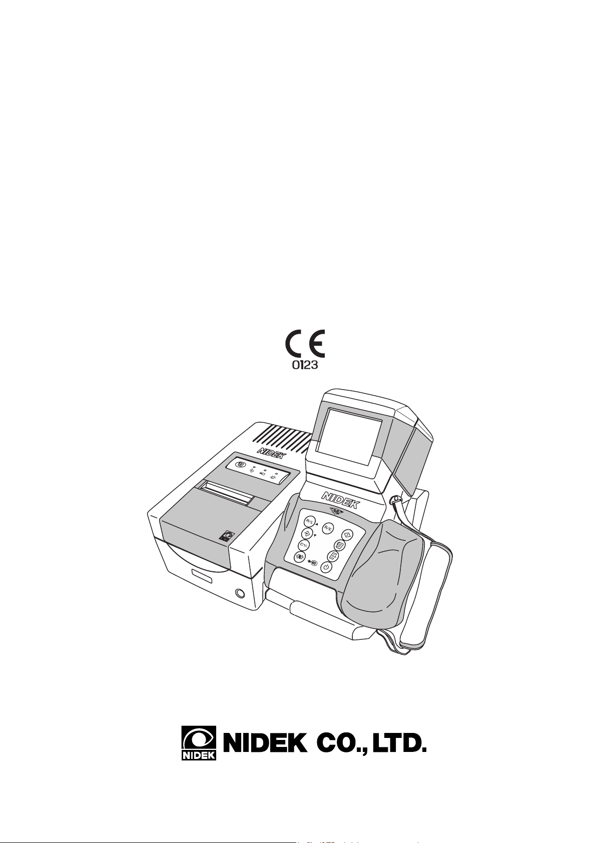
AUTO REF/KERATOMETER
ARK-30
Type R
OPERATOR’S MANUAL
Page 2

NIDEK CO., LTD. : 34-14, Maehama, Hiroishi-cho, Gamagori, Aichi 443-0038, Japan
(Manufacturer) Telephone: (0533) 67-6611
Facsimile: (0533) 67-6610
NIDEK CO., LTD : 6th Floor, Takahashi Bldg., No.2, 3-chome, Kanda-jinboucho
(Tokyo Office) Chiyoda-ku, Tokyo 101-0051, Japan
Telephone: (03) 3288-0571
Facsimile: (03) 3288-0570
Telex: 2226647 NIDEK J
NIDEK INCORPORATED : 47651 Westinghouse Drive Fremont, California 94539, U. S. A.
(United States Agent) Telephone: (510) 226-5700
Facsimile: (510) 226-5750
NIDEK SOCIETE ANONYME : Europarc 13, rue Auguste Perret, 94042 CRETEIL, France
(Authorized Representative) Telephone: (01) 49 80 97 97
Facsimile: (01) 49 80 32 08
2005.1
32725-P902G
Printed in JAPAN
Page 3
BEFORE USE OR MAINTENANCE, READ THIS MANUAL.
The Operator’s Manual contains information necessary for the operation of the NIDEK
AUTO REF/KERATOMETER Model ARK-30.
This manual includes operating procedures, cautions for safety, and specifications. The
device complies with ISO 10342 (Ophthalmic instruments - Eye refractometers). IEC
and UL standards are applied in this manual. The dioptric powers are indicated with
reference wavelength λd = 587.56 nm. For correct use, this manual is needed. Especially,
the cautions for safety and operating procedures must be thoroughly understood before
using the device. Keep this manual handy to verify use whenever necessary.
There are no user-serviceable parts inside the device except the printer paper, fuse, and
battery. If you encounter any problems or have questions about the device, contact your
authorized distributor.
(This applies only to the equipments whose power source is 100/120Vac.)
Page 4

Table of Contents
§
1 INTRODUCTION ........................................................................................................ 1-1
1.1 Outline of the Device ............................................................................................... 1-1
1.2 Indications for Use ................................................................................................... 1-1
1.3 Classifications .......................................................................................................... 1-1
1.4 Symbol Information ................................................................................................. 1-2
§
2 SAFETY ........................................................................................................................ 2-1
2.1 Cautions during Use ................................................................................................. 2-1
2.2 Storage ...................................................................................................................... 2-6
2.3 Transport................................................................................................................... 2-6
2.4 Installation ................................................................................................................ 2-7
2.5 Wiring....................................................................................................................... 2-8
2.6 After Use .................................................................................................................. 2-8
2.7 Maintenance and Checks .......................................................................................... 2-9
2.8 Disposal .................................................................................................................... 2-9
2.9 Labels ..................................................................................................................... 2-10
§
3 CONFIGURATION ..................................................................................................... 3-1
Page
§
4 OPERATING PROCEDURES.................................................................................... 4-1
4.1 Operation Flow ......................................................................................................... 4-1
4.2 Before First Use ....................................................................................................... 4-1
4.3 Measuring Procedures .............................................................................................. 4-4
4.4 AR (refractive error) & KM (corneal curvature radius) Measurements (R/K mode) ....
...................................................................................................................................... 4-18
4.5 AR (refractive error) Measurement (R mode) ........................................................ 4-20
4.6 KM (corneal curvature radius) Measurement (K mode) ........................................ 4-22
4.7 90º Angle Correction Function............................................................................... 4-24
4.8 Measurement Using Cable ..................................................................................... 4-26
4.9 Storing and Printing Measured Results .................................................................. 4-28
4.9.1 Storing measured results ............................................................................... 4-28
4.9.2 Printing stored data ....................................................................................... 4-30
4.9.3 Clearing measured results in memory ........................................................... 4-32
4.9.4 Confirming measured results in memory ...................................................... 4-33
4.10 Connection with External Devices ....................................................................... 4-34
4.10.1 Output to the RT or computer ..................................................................... 4-34
4.10.2 Input from the LM ....................................................................................... 4-36
4.10.3 Output to the IC card Reader/Writer ........................................................... 4-38
Page 5

4.10.4 Output to the IC card Reader/Writer (EyeCa-RW) ..................................... 4-40
4.11 Sagittal Radius Measurement ............................................................................... 4-42
§
5 PRINTOUT ................................................................................................................... 5-1
5.1 Printing Measured Values......................................................................................... 5-1
5.2 Other Prints .............................................................................................................. 5-5
5.2.1 Printout sample of stored data ......................................................................... 5-5
5.2.2 Printout sample of parameter .......................................................................... 5-6
§
6 OTHER FUNCTIONS ................................................................................................. 6-1
6.1 Parameter Settings .................................................................................................... 6-1
6.2 Setting Date and Time .............................................................................................. 6-9
6.3 Entering Comments ................................................................................................ 6-11
§
7 TROUBLESHOOTING GUIDE ................................................................................ 7-1
§
8 MAINTENANCE ......................................................................................................... 8-1
8.1 Replacing Printer Roll .............................................................................................. 8-1
8.2 Installing/Removing Battery .................................................................................... 8-3
8.3 Charging Battery ...................................................................................................... 8-4
8.4 Attaching/Detaching the Strap .................................................................................. 8-6
8.5 Attaching the Eye Mask ........................................................................................... 8-8
8.6 Replacing Fuses........................................................................................................ 8-9
8.7 Cleaning the Measuring Window ........................................................................... 8-10
8.8 Cleaning Exterior ................................................................................................... 8-11
8.9 Lists of Replacement Parts ..................................................................................... 8-11
Page
§
9 SPECIFICATIONS ...................................................................................................... 9-1
§
10ACCESSORIES .......................................................................................................... 10-1
10.1 Standard Accessories ............................................................................................ 10-1
10.2 Optional Accessories ............................................................................................ 10-1
§
11EMC (ELECTROMAGNETIC COMPATIBILITY).............................................. 11-1
APPENDIX. A GLOSSARY ................................................................................................. A-1
INDEX ........................................................................................................... End of this manual
Page 6

[This page is intentionally left blank.]
Page 7

INTRODUCTION
§
1
1.1 Outline of the Device
The NIDEK Auto Ref/Keratometer ARK-30 is an objective refraction measurement device that
contains the functions for measuring refractive errors such as spherical power, cylindrical power,
and cylinder axis and the functions for measuring corneal shapes such as the corneal curvature
radius (corneal refractive power), angle of meridian, and corneal cylindrical power.
The measured value of refractive errors are mainly used as the reference of the lens prescription
for correction of visual acuity in spectacle and contact lenses. The measured value of the corneal
curvature is used for the prescription of visual acuity corrective lenses such as contact lenses. It
is also used to observe the corneal curvature radius necessary for setting the refractive power of
intraocular lens that will be implanted after cataract surgery and the change process of the
postoperative corneal shape after corneal surgery.
This device is a hand-held type that allows children who cannot fix their head on the stationary
chinrest and lying patients to be measured. As well as the compact station, the device can be
easily moved, which makes the measurement possible in a sick room or operating room where
the measurement is not possible with the stationary type.
The device consists of a measuring unit and a station. The station is provided with a power supply,
a charger, and a printer to print the measured results. The measuring unit is provided with a color
LCD monitor and a control panel, etc. to perform alignment and operation.
To make the measurements easier, an auto-shot function is available, which will start the
measurement automatically when the patient’s eye is aligned and focused.
The built-in RS-232C interface allows you to output data to a personal computer.
1.2 Indications for Use
The Model ARK-30 Auto Ref/Keratometer is a diagnostic device that is indicated for use in the
automated measurement of refractive errors of the eye, and in the measurement of the corneal
curvature of the eye.
1.3 Classifications
[Classification under the provision of 93/42EEC (MDD)] Class IIa
The ARK-30 is classified as a Class IIa device.
[Form of protection against electrical shock] Class I
The ARK-30 is classified as a Class I device. The Class I device is a device in which protection
against electric shock does not rely solely on basic insulation. The Class I device includes
additional safety precaution that provides for a connection of accessible conductive parts to a
protective (earth) grounding conductor in the fixed wiring of the installation.
Use a power outlet which is equipped with a ground terminal.
Page 8
1 - 2
[Degree of protection against electrical shock] Type B applied part
The ARK-30 is provided with a Type B applied part.
The Type B applied part provides an adequate degree of protection against electrical shock,
particularly regarding the following:
- allowable leakage currents
- reliability of the protective earth ground connection (if applicable)
[Degree of protection against liquid entry] IP20*
The ARK-30 is classified as a normal device, as such provides only minimal protection against
liquid intrusion.
Avoid splashing water or another liquid on or in the device.
[Degree of protection against flammability]
The ARK-30 is classified as a device not suitable to be used in a potentially flammable
environment.
Do not operate the device near flammable type materials.
[Method (s) of sterilization or disinfection recommended by the manufacturer]
The forehead rest can be cleaned with a cloth dampened with rubbing alcohol as necessary.
[Mode of operation]
Classification of the ARK-30: Continuous operation
1
1.4 Symbol Information
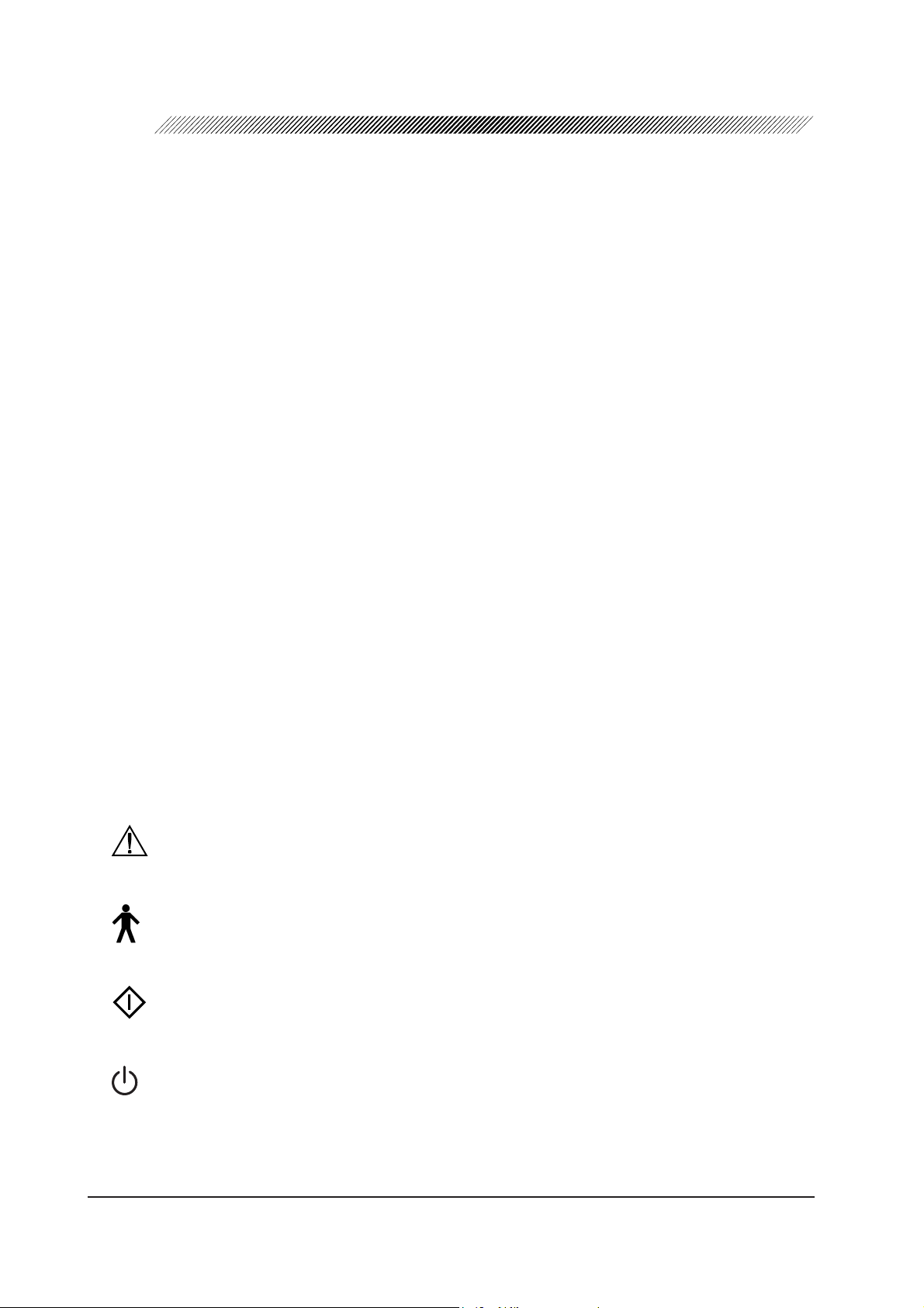
This symbol on the device indicates that caution must be taken.
Refer to the operator’s manual before use.
This symbol indicates that the degree of protection against electrical shock of the applied
part is classified as a Type B applied part.
This symbol on the control panel indicates the start button for placing the device in the
measurement mode.
This symbol on the control panel indicates the power button for turning the measuring
unit on and off. Pressing the button turns the measuring unit on and off.
*1 In accordance with IEC 60529
Page 9
1 - 3
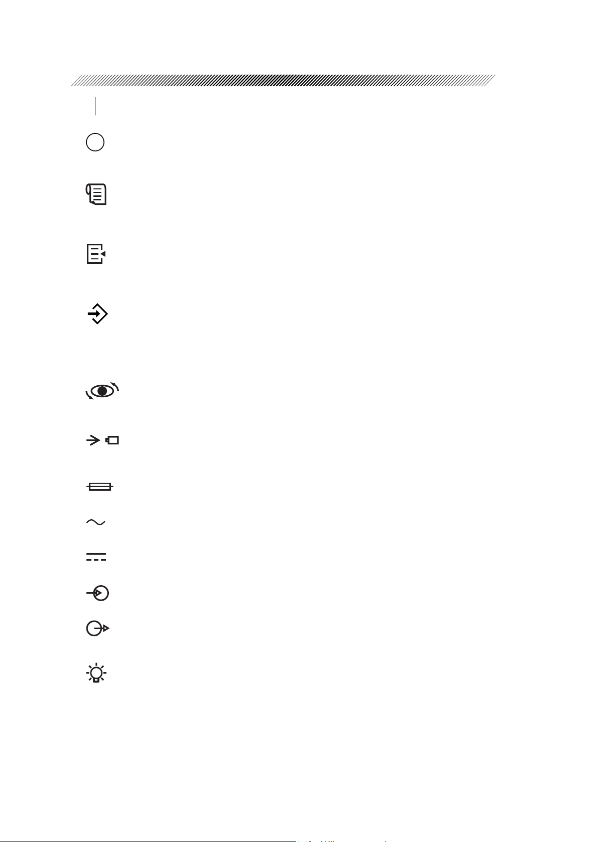
This symbol on the station indicates that the power is on.
This symbol on the station indicates that the power is off.
This symbol on the control panel indicates the print button for transmitting the measured
results to the station for printing out.
On the station, this symbol indicates the feed button for feeding the printer paper.
This symbol on the control panel indicates the parameter button for displaying the menu
to change the settings on the screen.
This symbol on the control panel indicates the memory button to store the median
values of the measured results.
On the station, the illuminated lamp for this symbol indicates that AR and KM data that
will be outputted externally are being stored in memory.
This symbol on the control panel indicates the angle correction button for rotating the
measuring optical axis 90°.
This is the symbol on the control panel and station. The lamp with this symbol flashes
while the battery is being charged.
This symbol indicates the fuse rating.
This symbol indicates that the device must be supplied only with alternating current.
This symbol indicates the connection part that is suitable for direct current only.
This indicates the input part.
This indicates the output part.
This symbol on the station indicates that power is supplied to the station and the power
switch is turned on when the lamp with this symbol is illuminated.
Page 10
SAFETY
§
2
In this manual, a Signal Word is used to designate the degree or level of safety alerting.
The definition is as follows:
CAUTION: Indicates a potentially hazardous situation which, if not avoided,
may result in minor or moderate injury or property damage accident.
Even situations indicated by “ CAUTION” may result in serious injury under certain
conditions. Safety precautions must be strictly followed at all times.
2.1 Cautions during Use
CAUTION
• Do not modify or touch the inside of the device.
This may result in an electric shock or a malfunction.
• Do not dismantle or modify the battery.
Heat generation, explosion, or combustion may result.
• Never remove the power cord from the wall outlet by holding on to the cord.
This may damage the cord and cause a short circuit or an electric shock. Grasp the plug
then pull.
• Do not place heavy objects on the power cord to prevent damage to the power cord, and
a fire or an electric shock.
• Immediately replace the power cord if the internal wires are exposed, the device power
turns on or off when the power cord is moved, or the cord and/or plug becomes extremely
hot.
This may result in an electric shock or a fire.
• Do not use the device for other than the intended purpose.
NIDEK will not be responsible for accidents or a malfunction caused by carelessness.
• Wipe between the prongs of the main plug with a dry cloth every once in a while.
If dust settles between the prongs, the dust will collect moisture, and a short circuit or a
fire may occur.
• Before measuring a patient, wipe the forehead rest with a clean cloth.
If necessary, wipe the forehead rest with a cloth dampened with rubbing alcohol.
Page 11
2 - 2
CAUTION
• In the event of a malfunction, do not touch the inside of the device, but disconnect the
power cord from the wall outlet and contact your authorized distributor.
• There may be cases where a measuring eye (R/L) is not detected correctly, depending on
the shape of the patient’s face.
Change the setting by pressing the R/L selection button
measuring eye side is not correct.
• When moving the device with your hand, use the hand strap or neck strap (option). To
move the device, be sure to hold the grip. Do not hold the hand strap only.
Accidentally dropping the device may cause an injury or a malfunction.
For a malfunction caused by dropping the device, the warranty is not valid. You must
pay to repair the device.
• Bring the device to the patient’s face after drawing out the forehead rest.
The device may contact the patient’s face.
if the indication of the
• Keep the measuring window free of fingerprints and dust to prevent the measurement
accuracy from decreasing.
• The date and time may deviate if the battery is removed from the measuring unit for more
than 12 hours. In this situation, reset the date and time.
• The measured values of objective refractive power obtained by the ARK-30 are intended
to be used as a reference of lens prescription for the correcton of visual acuity with spectacle
or contact lenses. Manifest refraction must be used as the basis for the spectacle or
contact lens prescription.
Page 12

2 - 3
CAUTION
• Information on the avoidance of overexposure to potentially hazardous optical radiation
(ISO 15004: 1997)
Spectrally weighted photochemical radiances LB and LA give a measure of the potential
that exists for a beam of light to cause photochemical hazard to the retina. LB gives the
measure for eyes in which the crystalline lens is in place. LA gives this measure either
for eyes in which the crystalline lens has been removed (aphakes) and has not been
replaced by a UV-blocking lens or for the eyes of very young children.
The value stated for this ophthalmic device gives a measure of hazard potential when
the device is operated at maximum intensity and maximum aperture. The values of L
or LB for the ARK-30 are sufficiently low as shown on the following page.
The retinal exposure dose for a photochemical hazard is a product of the radiance and
the exposure time. For instance, at a radiance level of 0.5 mW/(cm2•sr), 480 min
irradiation of the dilated (8 mm diameter) pupil would cause the retinal exposure dose
level to attain the recommended exposure limit. If the value of radiance were reduced
to 0.05 mW/(cm2•sr), ten times that time (i.e. 4800 min) would be needed to reach the
recommended limit. The recommended exposure dose is based on calculations arising
from the American Conference of Governmental Industrial Hygienists (ACGIH) Threshold Limit Values for Chemical Substances and Physical Agents (1995 - 1996
edition).
The following page shows the graph of spectrum output for the ARK-30. Patients will
be at low risk of acute optical radiation with the ARK-30. However, it is recommended
that the intensity of light directed into the patient’s eye be limited to the minimum level
which is necessary for diagnosis. The total of the retinal exposure dose must be carefully
watched for infants, aphakes and persons with diseased eyes who are at greater risk
when other ophthalmic devices with a high level of radiance are used in conjunction.
A
Page 13
2 - 4
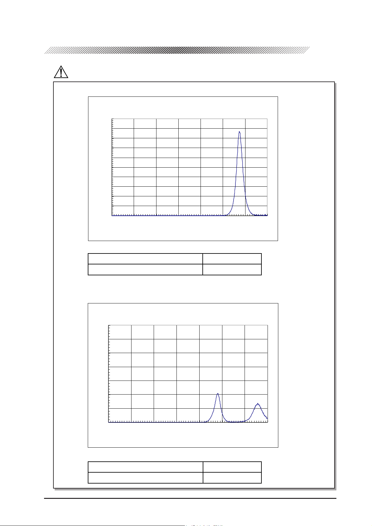
CAUTION
Spectrum output of all light source during AR measurement (maximum light intensity)
AR-20/ARK-30
ARK-30
10
9
8
7
6
5
4
3
Irradi-
ance:
放射照度:(μW/c㎡)
2
1
0
300 400 500 600 700 800 900 1000
Wavelength:
波長:(nm)
Spectrum irradiance
1
*
LA (µW/cm2/sr) 380 - 700 nm 0.527
B
2
*
(µW/cm2/sr) 305 - 700 nm 0.056
L
Spectrum output of all light source during KM measurement (maximum light intensity)
AR-20/ARK-30
ARK-30
7
6
5
4
3
2
Irradi-
ance:
放射照度:(μW/c㎡)
1
0
300 400 500 600 700 800 900 1000
Wavelength:
波長:(nm)
Spectrum irradiance
1
*
LA (µW/cm2/sr) 380 - 700 nm 0.002
B
2
*
(µW/cm2/sr) 305 - 700 nm 0.030
L
*1LA: Spectrally weighted photochemical aphakic source radiance
*2LB: Spectrally weighted photochemical phakic source radiance
Page 14
2 - 5
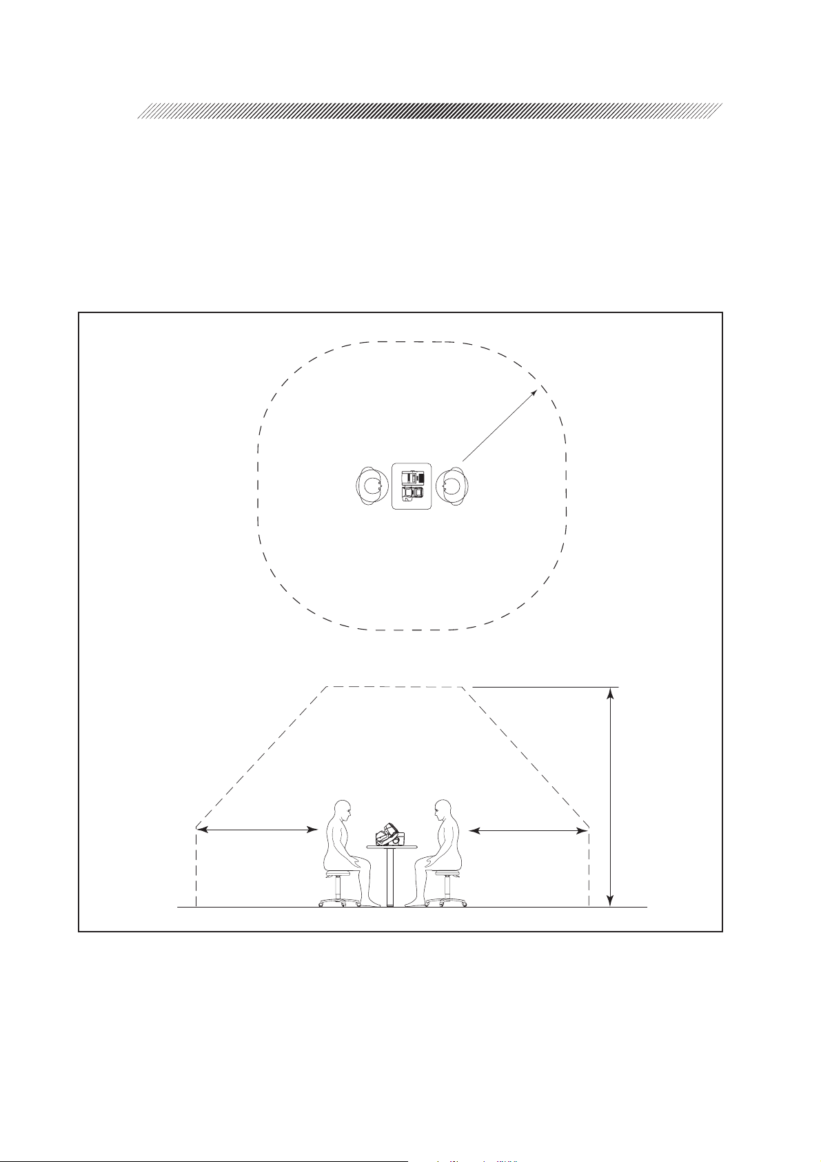
{ Patient environment
The patient environment represents a space where there is a possibility of direct contact between
the patient or the operator and third person.
When another type of device is used in the patient environment, use a device that complies
with IEC 60601-1. If the devices that do not comply with IEC 60601-1 are used, it is necessary
to use an isolating transformer to power the device or to connect the devices to additional
protective grounding.
Radius of 1.5 m
1.5 m
2.5 m
1.5 m
Page 15
2.2 Storage
CAUTION
• Store the device in a place that is dry and free from poisonous gas.
• The device must be maintained under the following conditions during transport and storage
(packed condition).
Environmental conditions Temperature: –20ºC to 60ºC
Humidity: 10% to 95% (No condensation)
A place with low dust
A place not exposed to direct sunlight
2.3 Transport
CAUTION
2 - 6
• Do not drag the cord or cables when moving the device to prevent an injury or a malfunction.
• Place the device in the shipping carton or optional carrying case when moving to another
location. Do not use the carrying case if you ask the moving company to take care of the
device.
Excessive vibration or impact may cause a device malfunction.
2.4 Installation
CAUTION
• Do not install the device near water.
Keep water away from the device to prevent an electric shock or a malfunction.
• Install the device on a stable and level surface free from vibration and impact to prevent
a malfunction or an injury caused by knocking over the device.
• For printing, wireless communication is performed using infrared beams from the
measuring unit to the station. Install the device where the light-receiver window of the
station is not exposed to intense light such as sunlight and illumination that contains
infrared rays.
If the intense external light comes into the light-receiver window, printing may not be
performed correctly. Cut off sunlight with a curtain and turn off nearby illumination.
Page 16
2 - 7
CAUTION
• Install the device in an environment that meets the following conditions.
Conditions in use Temperature: 10ºC to 40ºC
Humidity: 30% to 75% (No condensation)
Pressure: 700 hPa to 1060 hPa
A place with little dust
A place with little external light
A place free of vibration and impact
• This device complies with the limits for medical devices in IEC60601-1-2: 2001, EN60601-
1-2: 2001, and Medical Device Directive 93/42/EEC. These limits are designed to provide
reasonable protection against harmful interference in a standard medical installation. This
device generates, uses and can radiate radio frequency energy and, if not installed and
used in accordance with the instructions, may cause harmful interference to other devices
in the vicinity. However, there is no guarantee that interference will not occur in a particular
installation. If this device does cause harmful interference to other devices, which can be
determined by turning the device off and on, the user is encouraged to try to correct the
interference by one or more of the following measures:
- Reorient or relocate the receiving device.
- Increase the distance to the device.
- Correct the device into an outlet on a circuit different from that to which the other
device (s) are connected.
- Consult the manufacturer or field service technician for assistance.
• In installation and operation of the device, observe the following instructions about EMC
(electromagnetic compatibility):
- Do not use the device simultaneously with other electronic equipment to avoid
electromagnetic interference with the operation of the device.
- Do not use the device near, on, or under other electronic equipment to avoid
electromagnetic interference with the operation of the device.
- Do not use the device in the same room with other equipment such as life-support equipment,
other equipment that has major affects on the life of the patient and results of treatment, or
other measurement or treatment equipment that involves small electric current.
- Do not use the device simultaneously with portable and mobile radio frequency
communication systems because it may have an adverse effect on operation of the
device.
- Do not use cables and accessories that are not specified for the device because that
may increase the emission of electromagnetic waves from the device or the system
and decrease the immunity of the device to electromagnetic disturbance.
• The Electromagnetic Compatibility Directive sets the essential requirements for electrical
and electronic equipment that may disturb, or be disturbed by, other equipment. The ARK30 complies with these requirements as tabled on pages 11-1 to 11-3. Follow the guidance
in the tables for use of the device in an electromagnetic environment.
Page 17
2.5 Wiring
CAUTION
• Be sure to use a wall outlet which meets the requirements of the power specification.
If the line voltage is too high or too low, the device may not give full performance. A
malfunction or a fire may occur.
• Do not put many loads on one electrical outlet.
A fire may occur.
• Insert the mains plug into a grounded wall outlet.
An electric shock or a fire may occur in case of a device malfunction or power leakage.
• Securely connect the main plug into a wall outlet.
A loose connection may cause a fire.
• Be sure to connect the interface cable, checking the symbols of input (IN: ) and output
(OUT: ).
Correct communications will not be possible.
2 - 8
2.6 After Use
CAUTION
• If the device will not be used for a long time, disconnect the power cord from the wall
outlet to prevent a fire.
• If the device will not be used for a long time, remove the battery from the device to
prevent rust and deterioration of the battery.
• Store the battery with the contact away from metal.
The contact is recessed to prevent easy contact. However, if the battery is stored with a
metal necklace, etc., it may result in a short circuit, which may generate heat or a
malfunction.
• When the device is not in use, turn off the power and put the dust cover on the device to
prevent dust from affecting the measurement accuracy.
Page 18
2 - 9
2.7 Maintenance and Checks
CAUTION
• Use the specified fuses to replace the old ones to prevent a fire.
• Disassembly is not permitted except at NIDEK or your authorized distributor.
• Never use organic solvents such as paint thinner to wipe the exterior.
This may ruin the surface.
• When charging and replacing the battery, use the specified battery and charger (station or
measuring unit) only. In addition, do not put foreign matters such as metal into the battery
slot to prevent a malfunction or a fire.
• Do not discharge the battery in other devices. Do not connect the positive and negative
terminals with metal such as wire to prevent damage, deterioration, and shortened lifespan of the battery.
• Do not dismantle or modify the battery to prevent heat generation, explosion, or
combustion.
• Replace the printer paper with the specified paper only to prevent damage to the head.
• Before sending the device back to NIDEK for repair or maintenance, wipe the surface
(especially the area that contacts the patient’s skin) of the device with a clean cloth
immersed in ethyl alcohol for disinfection.
• Contact NIDEK or your authorized distributor to check whether the device needs the
measurement accuracy calibration if the AR-measured results are largely different from
the subjective measurements.
2.8 Disposal
CAUTION
• Follow local governing ordinances and recycling plans regarding disposal or recycling of
device components.
Especially the disposal method of lithium-ion batteries varies according to the
government. A rechargeable lithium battery is used in the device. Follow the local
governing ordinances and recycling plans when disposing of a board with lithium
batteries.
• When disposing of packing materials, sort them by material and follow the local ordinances
and recycling regulations.
Page 19
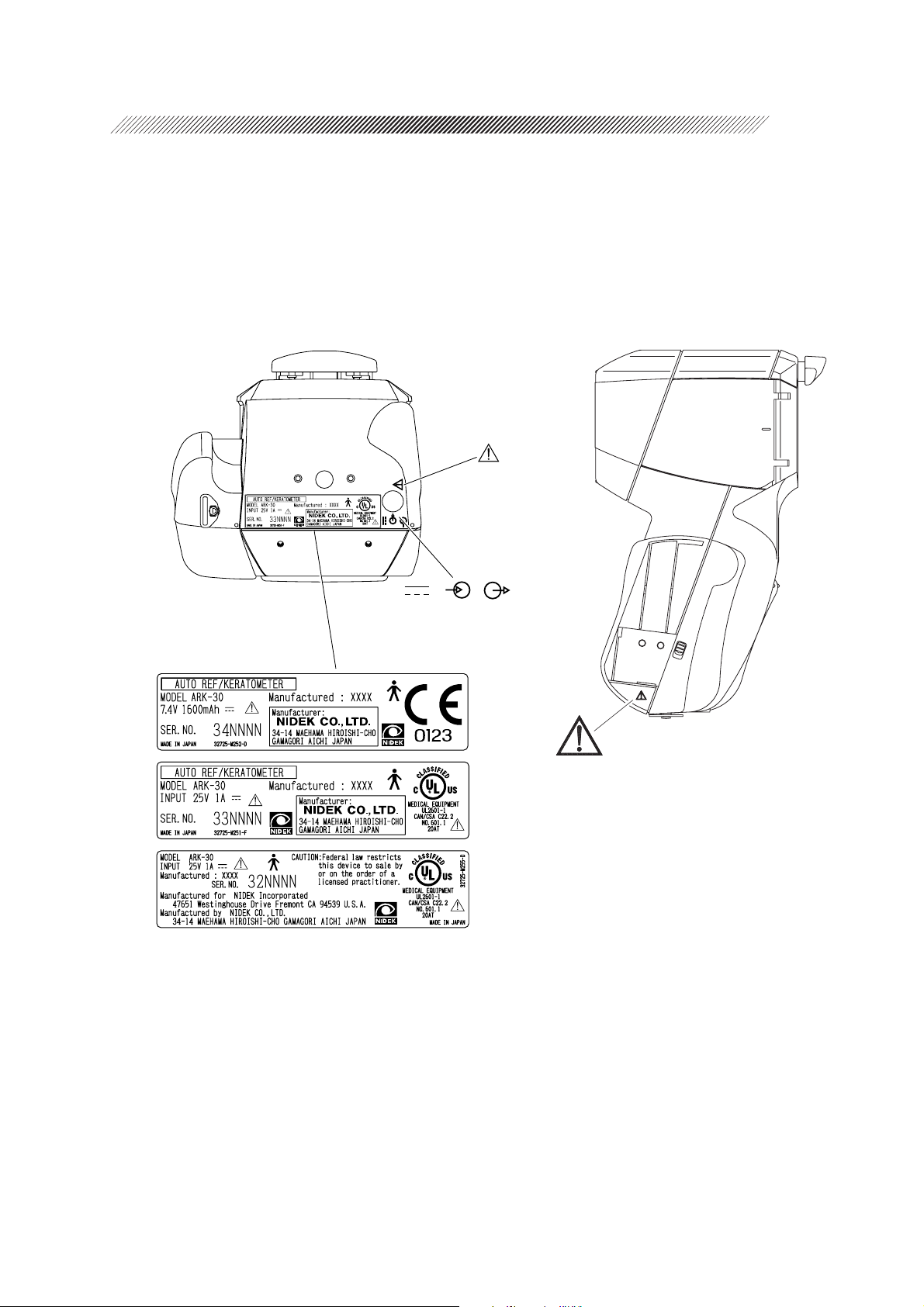
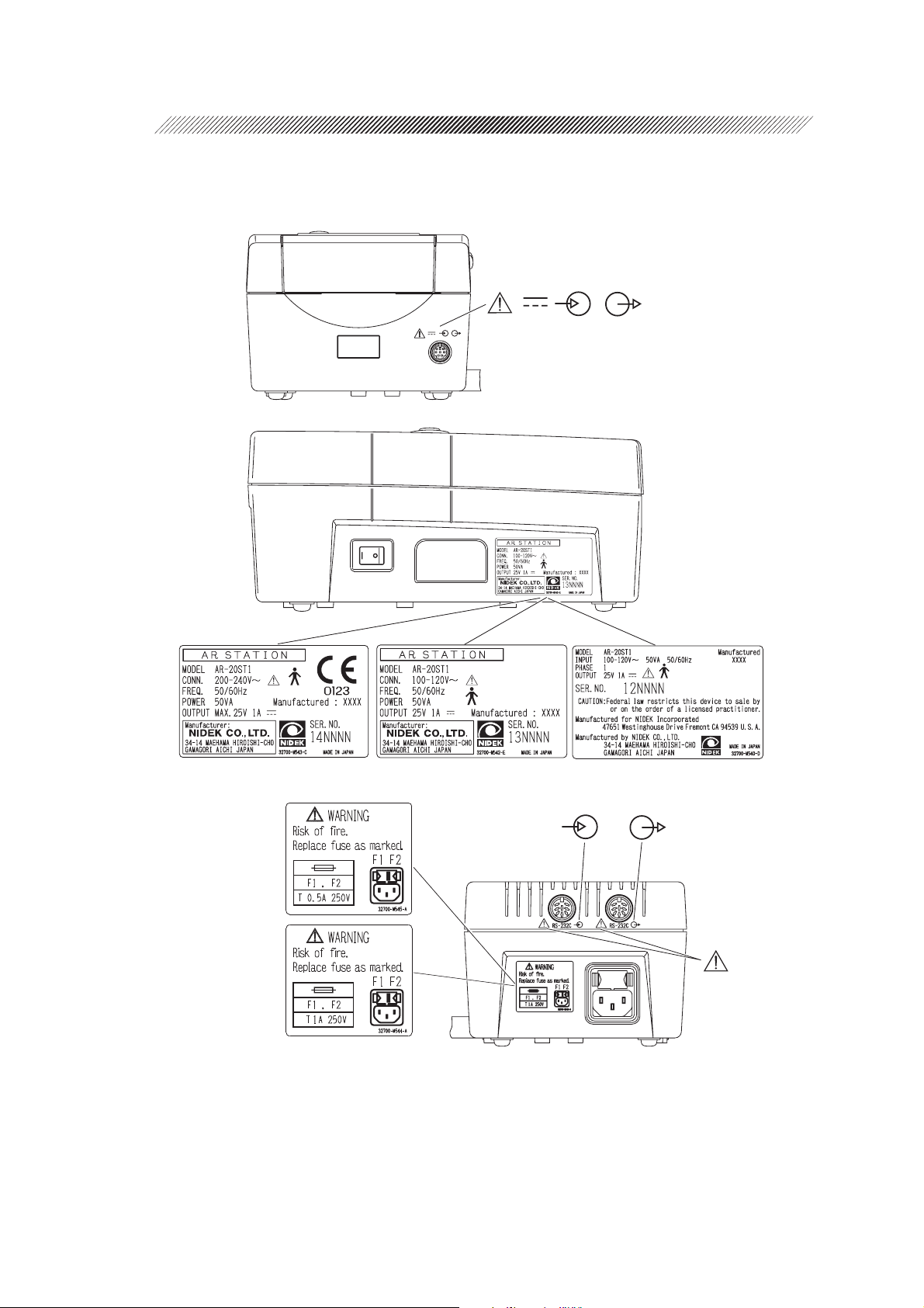
2.9 Labels
To catch the attention of the user, some labels and indications are provided on the device.
[Measuring unit]
2 - 10
Page 20
2 - 11
[Station]
200-240 V range
100-120 V range
Page 21
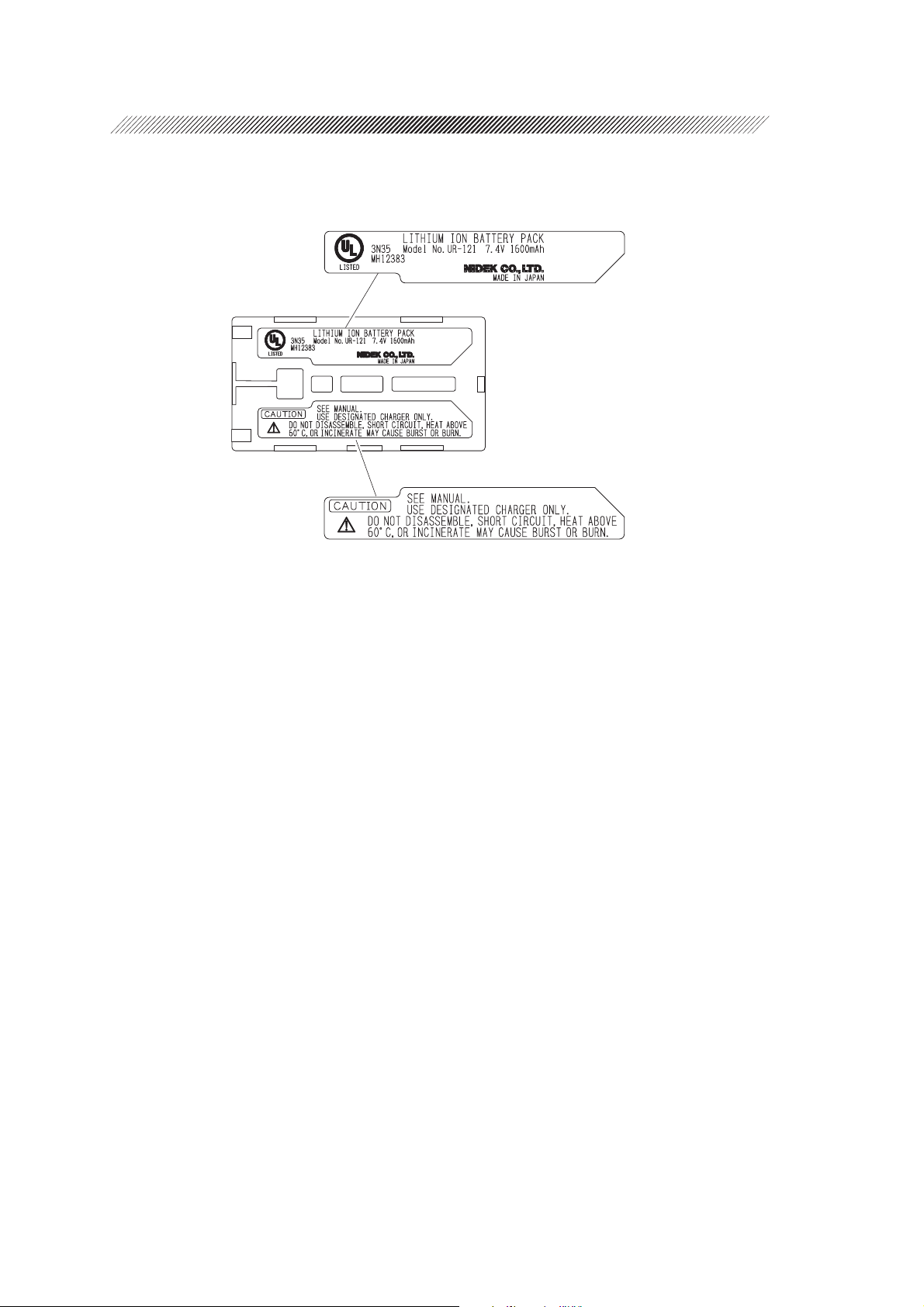
[Underside of battery]
2 - 12
Page 22
CONFIGURATION
§
3
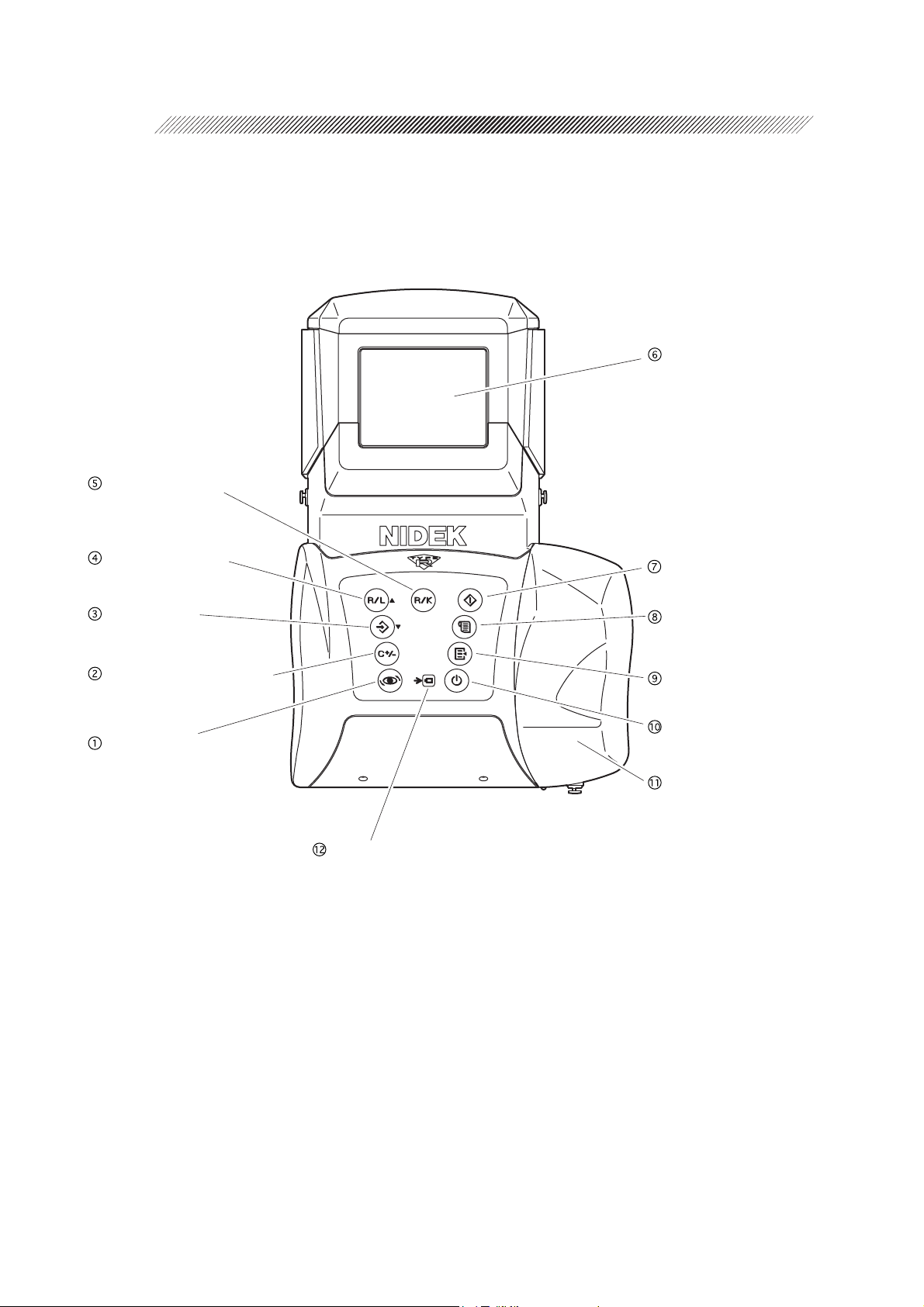
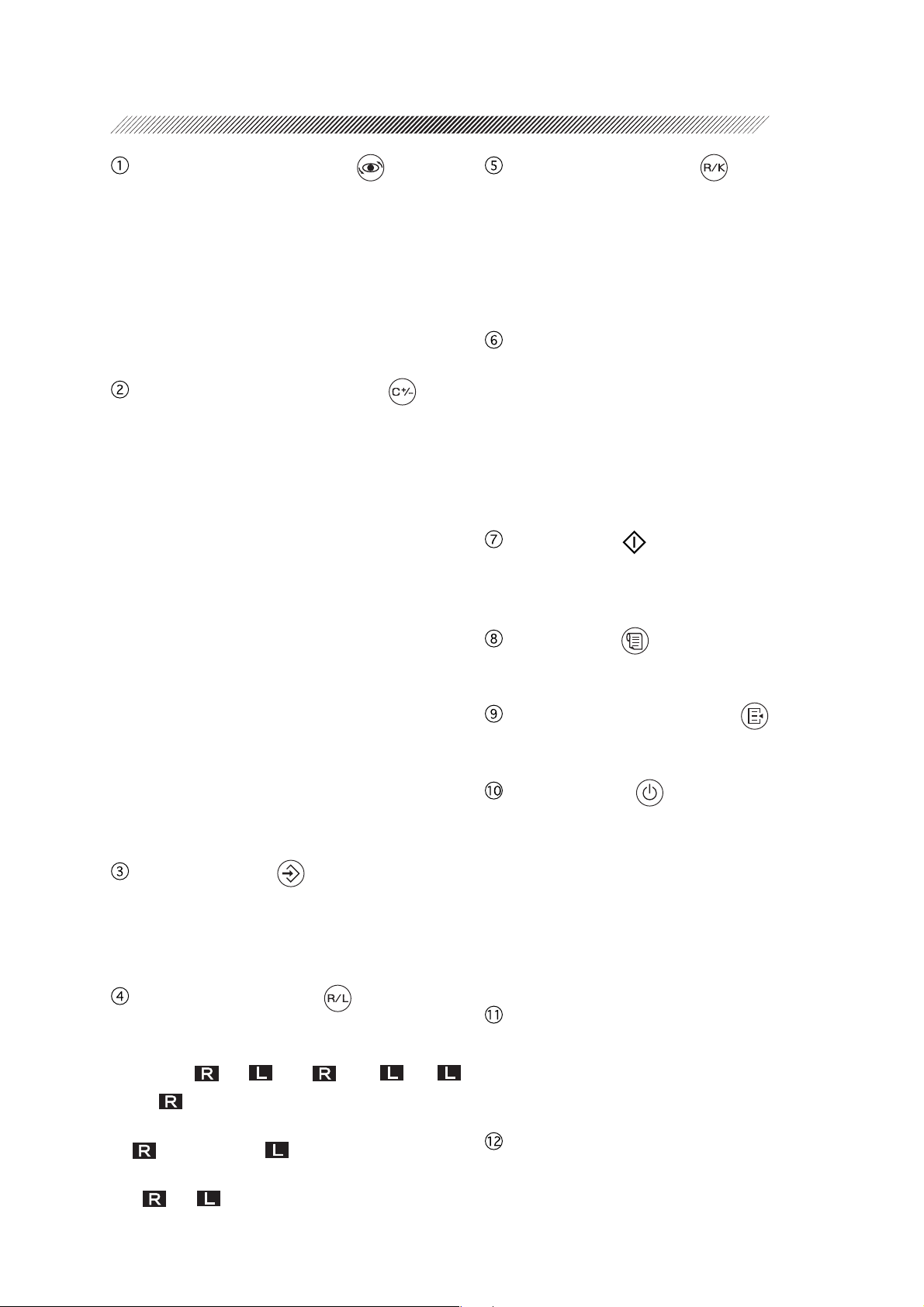
[Measuring unit]
R/K selection button
LCD screen
R/L selection button
Memory button
CYL mode selection button
Angle correction button
Start button
Print button
Parameter setting button
Power button
Grip
Charge indicator
Page 23
3 - 2
Angle correction button
Used to rotate the main body 90º when the
patient is measured from the side.
This is used to measure a patient who is
lying down.
When the parameter “41: SAGITTAL” is
set to “YES”, pressing this button starts
the sagittal radius measurement.
CYL mode selection button
Establishes the CYL mode of measured re-
sults. Pressing this button changes the mode
in the order of CYL – → CYL + → CYL ± →
CYL – → •••.
• CYL + (Plus reading)
Cylinder data is displayed by the + reading.
• CYL – (Minus reading)
Cylinder data is displayed by the – reading.
• CYL ± (Mix reading)
In the AR measurement, cylinder data is
displayed by the + reading when the refractive error is positive for any axis angle.
In other cases, cylinder data is displayed
by the – reading.
In the KM measurement, cylinder data is
displayed by the – reading.
See page 4-7 for details of the CYL mode.
Memory button
Stores the measured results in memory.
The memory function stores the measured
results of 30 patients (60 eyes).
R/K selection button
Changes the measurement mode.
The mode changes in the order of R/K
mode (Serial AR & KM measurements)→
R mode (AR measurement)→ K mode
(KM measurement)→ R/K mode→ •••.
LCD screen
Displays the patient’s eye, target, focusing
indicator, measured values, and measurement
count, etc.
The color of the characters and the background on the LCD screen can be selected
from a combination of 28 kinds.
Start button
Places the device into the measurable state
from standby.
Print button
Prints measured results, etc.
Parameter setting button
Used to change the settings of the device.
Power button
Turns the measuring unit on and off. Pressing this button turns on the power and viceversa.
Turning the power on places the device
into the standby mode.
The position of the chart is initialized and
the chart lamp lights up.
R/L selection button
Sets the measuring eye. Every time the button is pressed, the indication changes in the
order of (or )→ < >→ < >→
(or )→ •••.
If alignment is performed in the AUTO mode,
(right-eye) or (left-eye) will be identified automatically.
< > (< >) indicates that the right eye (left
eye) has been manually set.
Grip
Used to hold the measuring unit. The battery
holder is mounted inside. Open the cover to
replace the battery.
Charge indicator
Flashes while the battery in the measuring unit
is being charged.
Page 24
3 - 3
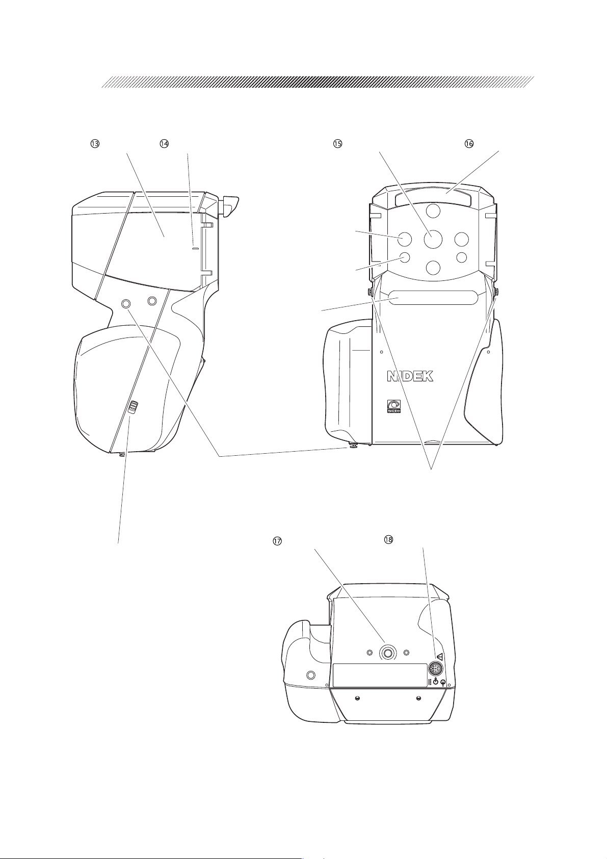
Measuring window Forehead restEye mask Eye level marker
Target detector window
Focus detector window
Window for optical
communications and
measuring eye (R/L)
detection
Lock switch
Slide this downward to
remove the grip cover.
Hand strap mounting hooks
Hand strap is to be attached to prevent
accidental drop.
Stand screw
Neck strap mounting hooks
Optional neck strap is to be attached.
Cable connector
Page 25

Eye mask
Open this mask to shield the patient’s eye
which is not measured.
This allows the patient to fixate his/her eye
easier.
To avoid damage from impact, the eye mask
is easily detached. To attach it, push lightly
aligning the hinge part with the main body.
Eye level marker
A guide for the patient’s eye level for measurements. It is located at both the front and
back sides of the eye mask.
Adjust the measuring unit so that the center of the patient’s eye is aligned with this
line.
3 - 4
Measuring window
The patient looks at the chart through this
window.
Keep this window clean. The measuring
window checker allows automatic confirmation of cleanliness.
Forehead rest
Place it against the patient’s forehead (top of
eyebrow) to stabilize the position of the measuring unit.
The push-type lock forehead rest can be
drawn out once it is pushed lightly.
Use the forehead rest so that the measuring unit will not contact the patient’s face.
Stand screw
This screw secures the measuring unit to the
portable stand (option).
Cable connector
Connector for the cable when the measuring
unit is used by deriving power from the station.
The battery can be recharged with the battery
installed in the measuring unit.
Printing is possible by the connecting cable.
Page 26
3 - 5
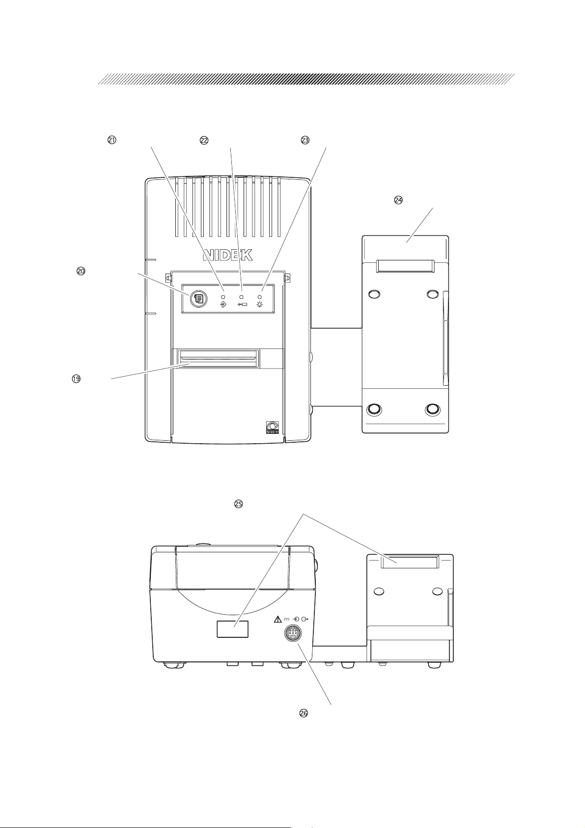
[Station]
Feed button
Printer
Memory lamp
Charge lamp
Pilot lamp
Measuring unit stage
Light-receiver window for printing
Cable connector
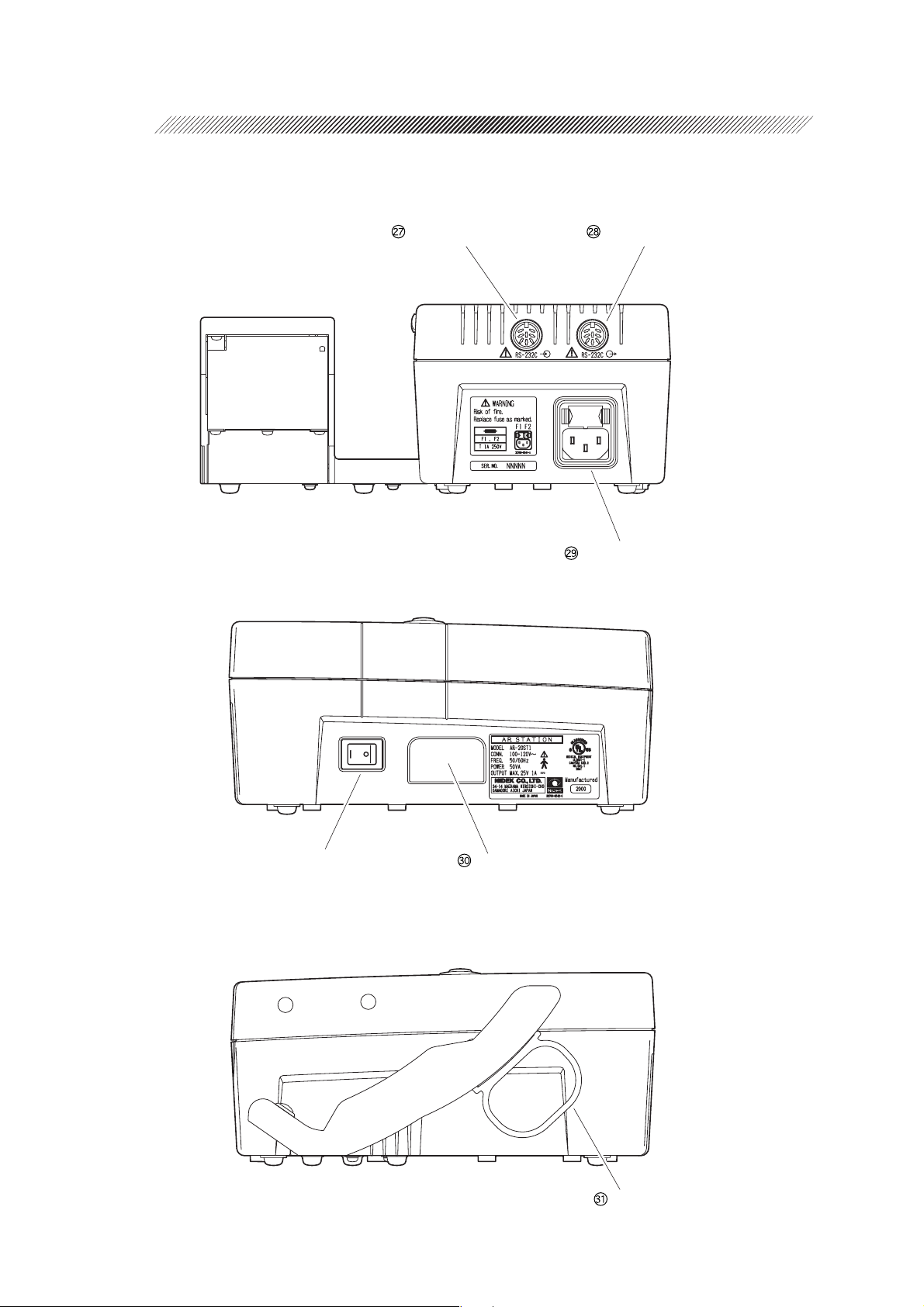
Page 27
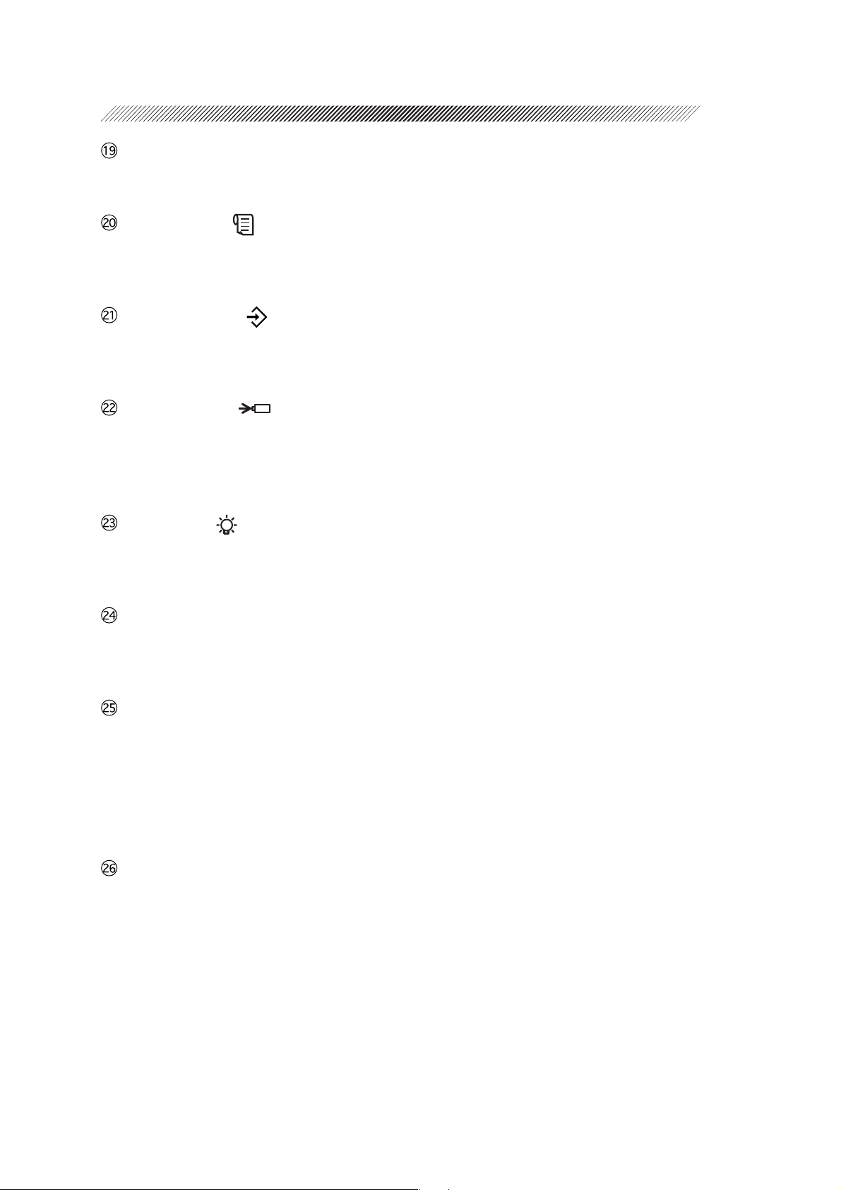
Printer
Prints measured results, etc.
Feed button ( )
Feeds the printer paper. While this button is
pressed, the paper is fed.
Memory lamp ( )
Illuminates while data to be transmitted to an
external computer, etc. is stored.
Charge lamp ( )
Flashes while the battery is being charged.
This lamp stays illuminated after the charging is completed.
Pilot lamp ( )
Illuminates when the station is supplied with
power and operating.
3 - 6
Measuring unit stage
The measuring unit is put on this stage when
not in use.
Light-receiver window for printing
Receives the signal from the measuring unit
during printing.
The communication distance between the
measuring unit and station is within 1
meter.
Cable connector
Connector for the cable when the measuring
unit is used by deriving power from the station.
Page 28
3 - 7
Data input connector Data output connector
Power connector
Power switch
Battery slot
Cable hanger
Page 29

Data input connector*
The interface cable from a lensmeter imports
measured values from the NIDEK’s
lensmeter.
The ARK-30 measured results are exported
from the data output connector. The imported
LM measured results are also exported from
the data output connector.
Data output connector*
The interface cable exports measured values
to an external computer.
Power connector
The supplied power cable is connected here.
This is the combination type with a fuse
holder.
Use the specified fuses.
Spare fuses are mounted in the spare fuse
holders inside the printer cover of the station.
3 - 8
Battery slot
The battery is inserted for recharge.
When the battery is inserted, charging will
start automatically and the charge lamp
( ) will flash.
Cable hanger
When the cable is not in use, it is placed on
this hanger.
The hanger can be easily detached since it
is attached by a magnet.
* Accessory equipment connected to the analog and digital interfaces must be certified according
to the appropriate national standards (for example, UL1950 for Data Processing Equipment
UL 2601-1 for Medical Equipment, and CSA C22.2 No. 601-1, EN 60601-1 and IEC 60601-
1.) Furthermore, all configurations shall comply with the system standard IEC 60601-1. Anyone
who connects additional equipment to the signal input part or signal output part is responsible
for making sure that the system complies with the requirements of the system standard IEC
60601-1. If in doubt, consult the technical service department or your local representative.
Page 30
3 - 9
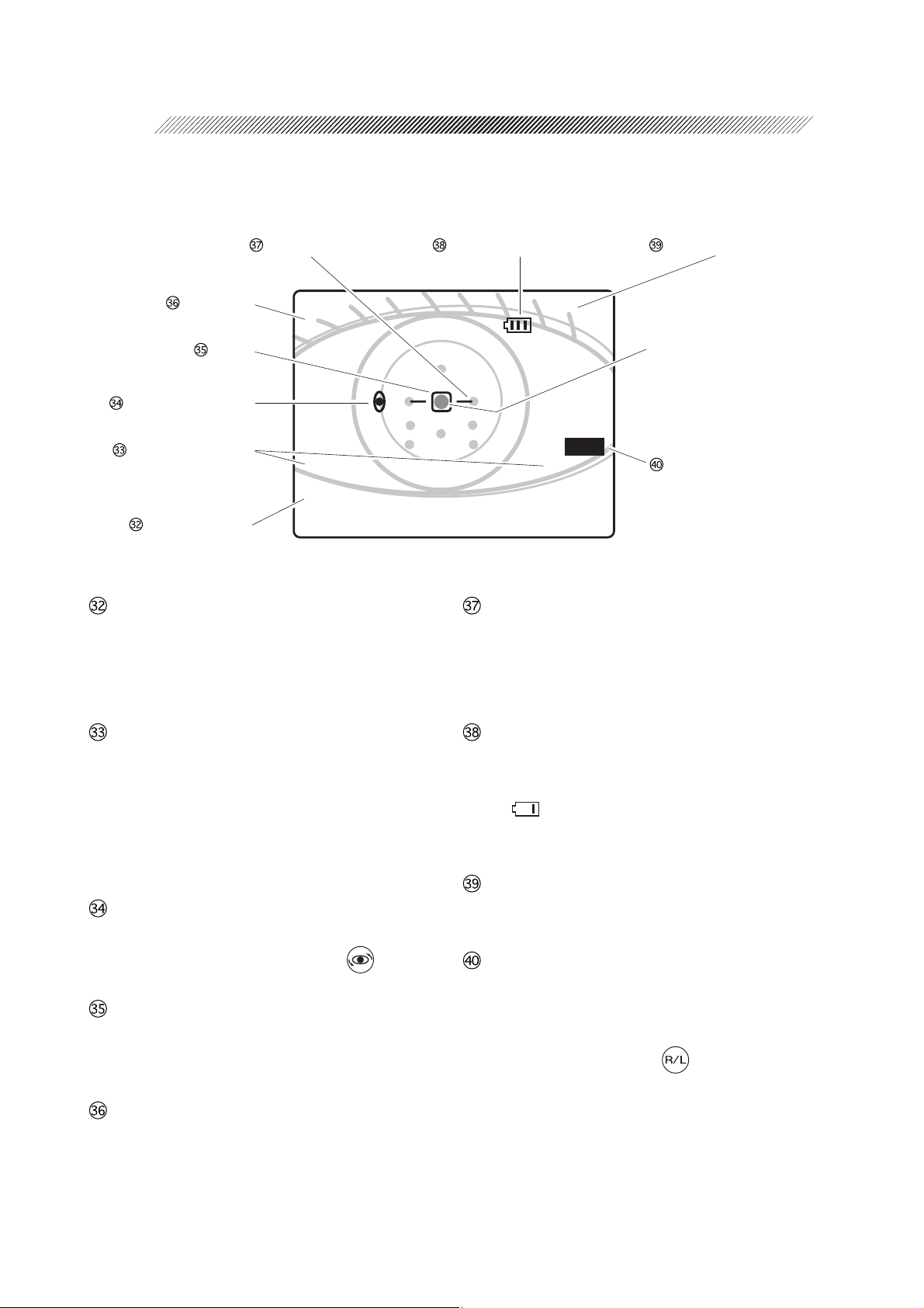
[LCD screen]
This is a sample measurement screen in the R/K mode.
Focusing indicator
Patient No.
㧺㧻㧚㧜㧜㧜㧝ޓޓޓޓޓޓޓޓޓ㧯㨅㧸㧙
Target
Axis correction mark
Measurement mode
Measured values
ޓޓޓޓޓޓޓޓޓޓޓޓޓޓޓޓޓޓ ޓޓ㧸
㧾㧦㧟ޓޓޓޓޓޓޓޓޓޓޓޓޓ㧷㧦㧟
㧿ޓ㧙ޓ㧠㧚㧡㧜ޓޓޓ㧾㧝ޓޓޓ㧣㧚㧣㧜
㧯ޓ㧙ޓ㧜㧚㧡㧜ޓޓޓ㧾㧞ޓޓޓ㧣㧚㧝㧜
㧭ޓޓޓޓޓ㧥㧜ޓޓޓ㧭㨄㧿ޓޓޓޓ㧠㧡
Measured values
Displays the latest measured results. The indicated items vary according to the measurement mode (R/K mode, R mode, K mode).
Battery remaining indicator
CYL mode indication
Corneal luminous spot
Other spots around are the
luminous spots of measuring light and sensor.
Measuring eye
Focusing indicator
Indicates the distance between the measuring
unit and the patient’s eye. This is a guide for
focusing.
Measurement mode
Indicates the selected measurement mode, R:
AR measurement, K: KM measurement, R
and K: R/K measurement. The figures shown
on the right and left represent the number of
measurements for each eye.
AXIS correction mark
This is shown when AXIS is corrected by 90º
with the angle correction button .
Target
Used to bring the patient’s eye to the center
of the measuring optical axis as a guide.
Patient No.
Displays the measured patient No. in a serial
number.
The number is set in the parameter setting
mode.
Battery remaining indicator
Indicates the remaining charge amount of the
battery installed in the measuring unit.
( ) indicates that the battery is getting
weak and the battery needs recharging.
CYL mode indication
Displays the established CYL mode.
Measuring eye
Displays the right-side or left-side of the detected patient’s eye.
This can be manually set by pressing the
R/L selection button .
Page 31

OPERATING PROCEDURES
§
4
4.1 Operation Flow
Power-ON
Measurements
→4.3 Measuring Procedures (p. 4-4)
→4.4 AR (refractive error) & KM (corneal curvature radius)
Measurements (p. 4-18)
→4.5 AR (refractive error) Measurement (p. 4-20)
→4.6 KM (corneal curvature radius) Measurement (p. 4-22)
→4.7 90° Angle Correction Function (p. 4-24)
→4.8 Measurement Using Cable (p. 4-26)
→4.9 Storing and Printing Measured Results
→4.9.1 Storing measured results (p. 4-28)
→4.9.2 Printing stored data (p. 4-30)
→4.11 Sagittal Radius Measurement (p. 4-42)
Power-OFF
(Determine final prescription by subjective refraction.)
4.2 Before First Use
1. Unpack the contents from the shipping carton and check them.
The standard configuration contains the following items:
• Measuring unit
• Station
• Cable
• Power cord (with 2 and 3 prong conversion plug)
• Battery
• Dust cover
• Hand strap (Attached to the measuring unit)
• Spare printer paper (3 rolls)
• Spare fuse (2)
• Operator’s manual (this book)
Spare fuses are mounted in the spare fuse
holders inside the printer cover of the station.
Spare fuse holder
Page 32

4 - 2
2. Put the station on a level surface such as a table and insert the power cord to the power
connector.
3. Insert the power cord into the wall outlet after making sure that the power switch is off
(½).
4. Turn the power switch on (
After the station is initialized, a short beep is produced twice and the pilot lamp ( ) turns on.
{{
{
{{
).
NOTE
• If abnormal conditions are encountered when the station is turned on (½), a short beep
is produced and the lamp turns on to notify the operator.
When the printer paper is all gone:
{
A beep is produced a few times and the pilot lamp ( ) flashes for about
ten minutes.
→ Set the printer paper.
When the printer head is up:
{
A beep is produced a few times and the charge lamp ( ) flashes for about
ten minutes.
→ The lever on the printer must be flipped down.
5. Charge the battery.
See “8.3 Charging Battery” for details.
It takes 120 - 150 minutes to fully recharge the battery (Takes much longer if the battery is
deteriorated.)
NOTE
• The battery is shipped with a full-charge. However, the battery may be self-discharged
if shipping takes a long time. It is recommended to recharge the battery before the first
use.
6. After preparing the charged battery, install the battery into the measuring unit.
See “8.2 Installing/Removing Battery” for details.
Attach the optional neck strap if available.
The hand strap and neck strap can be used at the same time.
See “8.4 Detaching/Attaching the Strap” for details.
Page 33

4 - 3
7. Press the power button on the measuring unit control panel and make sure that the
LCD screen illuminates.
After “HANDY REF/KERATOMETER ARK30”* appears, the initial screen is displayed.
㧴㧭㧺㧰㨅
㧾㧱㧲㧛㧷㧱㧾㧭㨀㧻㧹㧱㨀㧱㧾
㧭㧾㧷㧙㧟㧜
㧺㧵㧰㧱㧷
“PRESS BUTTON” appears in the center
of the screen and the device goes into the
standby mode.
In standby, the LCD screen is displayed, but
the measuring mechanism is not running.
8. Press the start button on the control
panel.
When “PRESS BUTTON” disappears, the
measuring unit goes into the measurement
mode.
The measurement mode is when the
measurement mechanism is running and the
measurement is ready to start.
㧺㧻㧚㧜㧜㧜㧝ޓޓޓޓޓޓޓޓޓ㧯㨅㧸㧙
㧼㧾㧱㧿㧿ޓޓ㧮㨁㨀㨀㧻㧺
ޓޓޓޓޓޓޓޓޓޓޓޓޓޓޓޓޓޓ ޓޓ㧸
㧾㧦㧜ޓޓޓޓޓޓޓޓޓޓޓޓޓ㧷㧦㧜
㧿ޓ㧗ޓ㧜㧚㧜㧜ޓޓޓ㧾㧝ޓޓޓ㧜㧚㧜㧜
㧯ޓ㧙ޓ㧜㧚㧜㧜ޓޓޓ㧾㧞ޓޓޓ㧜㧚㧜㧜
㧭ޓޓޓޓޓޓ㧜ޓޓޓ㧭㨄㧿ޓޓޓޓޓ㧜
㧺㧻㧚㧜㧜㧜㧝ޓޓޓޓޓޓޓޓޓ㧯㨅㧸㧙
ޓޓޓޓޓޓޓޓޓޓޓޓޓޓޓޓޓޓ ޓޓ㧸
㧾㧦㧜ޓޓޓޓޓޓޓޓޓޓޓޓޓ㧷㧦㧜
㧿ޓ㧗ޓ㧜㧚㧜㧜ޓޓޓ㧾㧝ޓޓޓ㧜㧚㧜㧜
㧯ޓ㧙ޓ㧜㧚㧜㧜ޓޓޓ㧾㧞ޓޓޓ㧜㧚㧜㧜
㧭ޓޓޓޓޓޓ㧜ޓޓޓ㧭㨄㧿ޓޓޓޓޓ㧜
9. Make the measuring and printing settings according to your usage pattern.
The settings can be changed anytime. Make the settings according to the usage.
See “6.1 Parameter Settings” for details.
This is all you have to do before use.
* “HANDY REF/KERATOMETER ARK-30” and “ARK-30 Type R” are nicknames. The official
model name of this device is “AUTO REF/KERATOMETER ARK-30”.
Page 34

4 - 4
4.3 Measuring Procedures
This is the procedure when the measuring unit is operating on the battery. There is no need to
turn on the station until printing measured results.
See “4.8 Measurement Using Cable” if the measuring unit is power-supplied from the station
via the cable.
CAUTION
• When the device is used, use the hand strap or neck strap (option).
Accidentally dropping the device may cause an injury or a malfunction.
1. Press the power button on the control panel.
1) The LCD screen illuminates and “HANDY REF/KERATOMETER ARK-30” appears.
2) After about three seconds, a beep is produced twice and the initial screen is displayed.
“PRESS BUTTON” appears in the center of the screen.
The screen displays the following: Patient No., Battery remaining indication, and CYL mode
are shown in the upper part, and Measuring eye (auto detected or ), Measurement count,
and Measurement items (initial setting: R/K mode) are shown in the lower part.
Battery remaining indicator
indicates that the battery needs charging.
(This is not shown when the device is used
via the cable.)
Patient No.
CYL mode
㧺㧻㧚㧜㧜㧜㧝ޓޓޓޓޓޓޓޓޓ㧯㨅㧸㧙
Measuring eye
(Auto-detected eye will be shown
with
KM measurement count
or .)
AR measurement count
㧼㧾㧱㧿㧿ޓޓ㧮㨁㨀㨀㧻㧺
ޓޓޓޓޓޓޓޓޓޓޓޓޓޓޓޓޓޓ ޓޓ㧸
㧾㧦㧜ޓޓޓޓޓޓޓޓޓޓޓޓޓ㧷㧦㧜
㧿ޓ㧗ޓ㧜㧚㧜㧜ޓޓޓ㧾㧝ޓޓޓ㧜㧚㧜㧜
㧯ޓ㧙ޓ㧜㧚㧜㧜ޓޓޓ㧾㧞ޓޓޓ㧜㧚㧜㧜
㧭ޓޓޓޓޓޓ㧜ޓޓޓ㧭㨄㧿ޓޓޓޓޓ㧜
Measurement items
S: Spherical power C: Cylindrical power A: Cylinder axis angle
R1: Flattest meridian R2: Steepest meridian AXS: Corneal cylinder axis angle
As for KM measured values, the following can be set according to the parameter setting.
AVE: Average of R1 and R2 CYL: Corneal cylindrical power AXS: Corneal cylinder axis angle
Page 35

4 - 5
2. Press the start button on the control panel.
“PRESS BUTTON” disappears and the measuring unit goes into the measurement mode*.
The LCD screen is displayed as follows. The target is shown in the center.
Target
㧺㧻㧚㧜㧜㧜㧝ޓޓޓޓޓޓޓޓޓ㧯㨅㧸㧙
ޓޓޓޓޓޓޓޓޓޓޓޓޓޓޓޓޓޓ ޓޓ㧸
㧾㧦㧜ޓޓޓޓޓޓޓޓޓޓޓޓޓ㧷㧦㧜
㧿ޓ㧗ޓ㧜㧚㧜㧜ޓޓޓ㧾㧝ޓޓޓ㧜㧚㧜㧜
㧯ޓ㧙ޓ㧜㧚㧜㧜ޓޓޓ㧾㧞ޓޓޓ㧜㧚㧜㧜
㧭ޓޓޓޓޓޓ㧜ޓޓޓ㧭㨄㧿ޓޓޓޓޓ㧜
{ Checking the measuring window before use
Whether to check the measuring window cleanliness can be set by setting the parameter.
An unclean measuring window will decrease the reliability of measurements. This checker as
well as visual inspection should be used for measurements under clean conditions.
See “6. OTHER FUNCTIONS” for details.
1) Press the start button in the standby status.
“MEASURING WINDOW CHECKING”
appears and the measuring window starts
㧺㧻㧚㧜㧜㧜㧝ޓޓޓޓޓޓޓޓޓ㧯㨅㧸㧙
ޓޓ㧹㧱㧭㧿㨁㧾㧵㧺㧳ޓ㨃㧵㧺㧰㧻㨃
ޓޓޓޓޓޓ㧯㧴㧱㧯㧷㧵㧺㧳
checking.
Wait until a message appears.
NOTE
ޓޓޓޓޓޓޓޓޓޓޓޓޓޓޓޓޓޓ ޓޓ㧸
㧾㧦㧜ޓޓޓޓޓޓޓޓޓޓޓޓޓ㧷㧦㧜
㧿ޓ㧗ޓ㧜㧚㧜㧜ޓޓޓ㧾㧝ޓޓޓ㧜㧚㧜㧜
㧯ޓ㧙ޓ㧜㧚㧜㧜ޓޓޓ㧾㧞ޓޓޓ㧜㧚㧜㧜
㧭ޓޓޓޓޓޓ㧜ޓޓޓ㧭㨄㧿ޓޓޓޓޓ㧜
• When checking the measuring window, keep objects off the front of the measuring
window. Even if the measuring window is clean, the message “NG!” may appear due
to obstructing objects. The message also may appear when the window is checked
with the measuring unit on the station or a table.
2) A message appears.
When “OK!” appears:
The measuring windos is clean. After the
message diappears, the device goes into the
㧺㧻㧚㧜㧜㧜㧝ޓޓޓޓޓޓޓޓޓ㧯㨅㧸㧙
ޓޓ㧹㧱㧭㧿㨁㧾㧵㧺㧳ޓ㨃㧵㧺㧰㧻㨃ޓޓ
ޓޓޓޓޓޓޓޓ㧻㧷㧍
normal measurement mode.
When “NG!” appears:
Turn the power off and check that the
measuring window is clean. If not, clean it.
ޓޓޓޓޓޓޓޓޓޓޓޓޓޓޓޓޓޓ ޓޓ㧸
㧾㧦㧜ޓޓޓޓޓޓޓޓޓޓޓޓޓ㧷㧦㧜
㧿ޓ㧗ޓ㧜㧚㧜㧜ޓޓޓ㧾㧝ޓޓޓ㧜㧚㧜㧜
㧯ޓ㧙ޓ㧜㧚㧜㧜ޓޓޓ㧾㧞ޓޓޓ㧜㧚㧜㧜
㧭ޓޓޓޓޓޓ㧜ޓޓޓ㧭㨄㧿ޓޓޓޓޓ㧜
Page 36

4 - 6
NOTE
• The checker works only before the first measurement after the power has been turned
on. Regardless of the message “OK!” or “NG!”, the checker does not work after the
second measurement or later.
3. Establish the measurement conditions, etc. according to your usage pattern.
a. Parameter setting button
See “6. Other Functions” for details.
NOTE
• The following table includes the parameters related to the measuring procedure and
measured results. Make the settings according to your usage pattern.
If not necessary, there is no need to change the parameters as they are stored in the
device.
* The underlined items indicate factory-settings.
No . Parameter De scriptio n
STEP 0.12D / 0.25D
1
VERTEX D.
2
KM UNIT mm
3
KM DISP. R1, R2
4
AXIS STEP 1°
5
AI MODE YES
7
AUTO IO L YES
21
REF. INDEX 1.3375
24
0 mm / 10.5 mm / 12 mm
15 mm / 16.5 mm
/ D
/ AVE, CYL
/ 5°
/ NO
/ NO
/ 1.336 / 1.332
/ 13.75 mm (default for N. Inc.) /
* Power-saving function
There are two functions for power savings.
1. The device returns to standby when not operated for approximately one minute in the
measurement mode.
2. When the parameter “23. AUTO OFF” is set to “10”, the light quantity of the LCD back
light is reduced and the chart lamp goes out if the device is not operated for approximately
three minutes after standby.
Press the start button to place the device in the measurement mode.
b. CYL mode selection button
Page 37

4 - 7
This is the button to change the indication of the cylinder value (cylindrical power).
CYL – ....Cylinder data is displayed by the – reading.
CYL + ....Cylinder data is displayed by the + reading.
CYL ± ....In the AR measurement, cylinder data is displayed by the + reading when the
refractive error is positive for any axis angle. In other cases, cylinder data is
displayed by the – reading.
In the KM measurement, cylinder data is displayed by the – reading.
Screen indication CYL– CYL
AR measurement Minus reading Plus reading Mix reading
KM measurement Minus reading Plus reading Minus reading
* The mode can be changed even after the measurement.
* All stored data are printed in the mode when printing.
+
CYL
±
NOTE
• Corneal cylindrical power (CYL) axis (AXIS) indication of KM measured values
according to CYL mode
Minus reading
• For AVE, CYL indication, CYL (cylindrical power) is displayed by – and AXIS
indicates the flattest meridian curvature radius direction.
• For R1, R2 indication, AXIS indicates the flattest meridian curvature radius (R1)
direction.
Plus reading
• For AVE, CYL indication, CYL (cylindrical power) is displayed by + and AXIS
indicates the steepest meridian curvature radius direction.
• For R1, R2 indication, AXIS indicates the steepest meridian curvature radius
(R2) direction.
Page 38

4 - 8
4. Press the R/K selection button to select a measurement mode.
The R/K mode is the initial setting. Operation is not necessary when the eye is measured
continuously in the R/K mode.
The measurement items corresponding to the selected measurement mode are displayed on the
screen.
The mode changes in the order of R/K → R → K → R/K →•••.
R / K mode ••• AR & KM serial measurements
R mode ••• AR measurement
Values are not displayed for the KM
measurement items.
K mode ••• KM measurement
Values are not displayed for the AR
measurement items.
㧺㧻㧚㧜㧜㧜㧝ޓޓޓޓޓޓޓޓޓ㧯㨅㧸㧙
ޓޓޓޓޓޓޓޓޓޓޓޓޓޓޓޓޓޓ ޓޓ㧸
㧾㧦㧜ޓޓޓޓޓޓޓޓޓޓޓޓޓ㧷㧦㧜
㧿ޓ㧗ޓ㧜㧚㧜㧜ޓޓޓ㧾㧝ޓޓޓ㧜㧚㧜㧜
㧯ޓ㧙ޓ㧜㧚㧜㧜ޓޓޓ㧾㧞ޓޓޓ㧜㧚㧜㧜
㧭ޓޓޓޓޓޓ㧜ޓޓޓ㧭㨄㧿ޓޓޓޓޓ㧜
㧺㧻㧚㧜㧜㧜㧝ޓޓޓޓޓޓޓޓޓ㧯㨅㧸㧙
ޓޓޓޓޓޓޓޓޓޓޓޓޓޓޓޓޓޓ ޓޓ㧸
㧾㧦㧜ޓޓޓޓޓޓޓޓޓޓޓޓޓޓޓޓ
㧿ޓ㧗ޓ㧜㧚㧜㧜ޓޓޓ㧾㧝ޓޓޓޓޓޓޓ
㧯ޓ㧙ޓ㧜㧚㧜㧜ޓޓޓ㧾㧞ޓޓޓޓޓޓޓ
㧭ޓޓޓޓޓޓ㧜ޓޓޓ㧭㨄㧿ޓޓޓޓޓޓ
㧺㧻㧚㧜㧜㧜㧝ޓޓޓޓޓޓޓޓޓ㧯㨅㧸㧙
ޓޓޓޓޓޓޓޓޓޓޓޓޓޓޓޓޓޓ ޓޓ㧸
ޓޓޓޓޓޓޓޓޓޓޓޓޓޓޓޓ㧷㧦㧜
㧿ޓޓޓޓޓޓޓޓޓޓ㧾㧝ޓޓޓ㧜㧚㧜㧜
㧯ޓޓޓޓޓޓޓޓޓޓ㧾㧞ޓޓޓ㧜㧚㧜㧜
㧭ޓޓޓޓޓޓޓޓޓޓ㧭㨄㧿ޓޓޓޓޓ㧜
Page 39

5. Prepare the patient and measuring unit.
4 - 9
1) Draw out the forehead rest.
The push-type lock forehead rest can be
drawn out once it is pushed lightly.
To prevent the forehead rest from popping
out accidentally, you are recommended to
perform alignment after drawing out the
forehead rest.
2) Clean the forehead rest with a clean cloth
such as a gauze.
If necessary, wipe with a cloth soaked in
rubbing alcohol.
3) Open the eye mask.
Covering the idle eye with the eye mask
stabilizes the other eye.
NOTE
Eye masks
Forehead rest
• The eye masks are configured to be detached by impact to prevent an injury or a device
malfunction.
If the mask is detached by impact, push it lightly to set, aligning the hinge part with
the main body. (See “8.5 Attaching the Eye Mask”.)
4) Instruct the patient to take off eye glasses or contact lenses and sit on a chair.
To measure a patient lying down, correct the CYL axis angle. See “4.7 90° Axis Correction
Function” for details.
NOTE
• Give the following explanation to help the patient relax before the measurement.
“This device measures your eye with a weak infrared ray to find which kind of lens
is suitable. The infrared ray does not harm your eyes.”
Page 40

4 - 10
6. Perform alignment.
Confirm the luminous spots on the cornea on the LCD screen and perform alignment until the
central corneal luminous spot is placed inside the target.
1) Instruct the patient, “Look through the
measuring window. You will see a picture
of a balloon, watch the center of it without
straining.”
2) Bring the measuring unit close to the
patient’s eye and place the forehead rest
against the forehead (top of eyebrow).
In this case, the eye level marker acts as a
guide for the vertical position.
NOTE
Scenic picture with balloon
Eye level marker
• When holding the measuring unit with
your left hand too, do not cover the
detection windows with your fingers.
Detection will fail and correct
measurement may not be possible.
Target detector window
Focus detector window
Measuring eye detector window
Page 41

3) Adjust the position of the measuring unit
so that the patient’s eye appears on the LCD
screen.
Adjust the focus with back and forth
movements (focus on the patient’s eye).
Either side of the patient’s eye may be
measured first.
4) Make sure that the left-eye or right-eye
indication of the measuring eye is properly
shown.
Normally, the left eye or right eye is
automatically detected, but detection may
not occur properly depending on the
condition of the measuring eye.
In this case, press the R/L selection button
to select the applicable eye.
When the manual setting is completed, the
indication changes from / to < >/
< >.
4 - 11
㧺㧻㧚㧜㧜㧜㧝ޓޓޓޓޓޓޓޓޓ㧯㨅㧸㧙
ޓޓޓޓޓޓޓޓޓޓޓޓޓޓޓޓޓޓ ޓޓ㧸
㧾㧦㧜ޓޓޓޓޓޓޓޓޓޓޓޓޓ㧷㧦㧜
㧿ޓ㧗ޓ㧜㧚㧜㧜ޓޓޓ㧾㧝ޓޓޓ㧜㧚㧜㧜
㧯ޓ㧙ޓ㧜㧚㧜㧜ޓޓޓ㧾㧞ޓޓޓ㧜㧚㧜㧜
㧭ޓޓޓޓޓޓ㧜ޓޓޓ㧭㨄㧿ޓޓޓޓޓ㧜
㧺㧻㧚㧜㧜㧜㧝ޓޓޓޓޓޓޓޓޓ㧯㨅㧸㧙
ޓޓޓޓޓޓޓޓޓޓޓޓޓޓޓޓޓޓ ޓ 㧸
㧾㧦㧜ޓޓޓޓޓޓޓޓޓޓޓޓޓ㧷㧦㧜
㧿ޓ㧗ޓ㧜㧚㧜㧜ޓޓޓ㧾㧝ޓޓޓ㧜㧚㧜㧜
㧯ޓ㧙ޓ㧜㧚㧜㧜ޓޓޓ㧾㧞ޓޓޓ㧜㧚㧜㧜
㧭ޓޓޓޓޓޓ㧜ޓޓޓ㧭㨄㧿ޓޓޓޓޓ㧜
Indication of measuring eye
“< >” mark indicates the right eye or
left eye has been specified manually.
NOTE
• Error message function of R/L auto detection
The R/L auto detection may not normally
work under such a specific condition that
the patient wears a gauze mask. In this
situation, and flashes and “R/L?”
is displayed for an error message.
The measurement does not start when the
error message is displayed.
If the R/L auto detection is normally performed by removing the mask, or R or L is
manually set with the R/L selection button , the measurement can be started.
5) Perform fine alignment.
Adjust the position of the measuring unit
until the corneal luminous spot is placed
inside the target “ ”.
㧺㧻㧚㧜㧜㧜㧝ޓޓޓޓޓޓޓޓޓ㧯㨅㧸㧙
ޓ㧾ޓޓޓޓޓޓ㧾㧛㧸㧫ޓޓޓޓޓޓ㧸
㧾㧦㧜ޓޓޓޓޓޓޓޓޓޓޓޓޓ㧷㧦㧜
㧿ޓ㧗ޓ㧜㧚㧜㧜ޓޓޓ㧾㧝ޓޓޓ㧜㧚㧜㧜
㧯ޓ㧙ޓ㧜㧚㧜㧜ޓޓޓ㧾㧞ޓޓޓ㧜㧚㧜㧜
㧭ޓޓޓޓޓޓ㧜ޓޓޓ㧭㨄㧿ޓޓޓޓޓ㧜
“R/L?” error message
㧺㧻㧚㧜㧜㧜㧝ޓޓޓޓޓޓޓޓޓ㧯㨅㧸㧙
ޓޓޓޓޓޓޓޓޓޓޓޓޓޓޓޓޓޓ ޓޓ㧸
㧾㧦㧜ޓޓޓޓޓޓޓޓޓޓޓޓޓ㧷㧦㧜
㧿ޓ㧗ޓ㧜㧚㧜㧜ޓޓޓ㧾㧝ޓޓޓ㧜㧚㧜㧜
㧯ޓ㧙ޓ㧜㧚㧜㧜ޓޓޓ㧾㧞ޓޓޓ㧜㧚㧜㧜
㧭ޓޓޓޓޓޓ㧜ޓޓޓ㧭㨄㧿ޓޓޓޓޓ㧜
Corneal luminous spot on patient’s eye
Page 42

4 - 12
7. Adjust the focus.
When the corneal luminous spot is placed inside
the target, the focusing indicator appears.
If the focusing indicator does not appear, it
means that the eye is not positioned in the range
of focus detection.
Adjust the focus, paying attention to keep the
measuring unit horizontal to the patient and not
to misalign the target. Tilt will cause an error
in the AXIS value.
1) Move the measuring unit back and forth until the focusing indicator shows the best state
“ ”.
Too close to the patient’s eye.
The bar increases as the measuring unit is moving closer to the patient’s
eye (maximum four bars).
㧺㧻㧚㧜㧜㧜㧝ޓޓޓޓޓޓޓޓޓ㧯㨅㧸㧙
ޓޓޓޓޓޓޓޓޓޓޓޓޓޓޓޓޓޓ ޓޓ㧸
㧾㧦㧜ޓޓޓޓޓޓޓޓޓޓޓޓޓ㧷㧦㧜
㧿ޓ㧗ޓ㧜㧚㧜㧜ޓޓޓ㧾㧝ޓޓޓ㧜㧚㧜㧜
㧯ޓ㧙ޓ㧜㧚㧜㧜ޓޓޓ㧾㧞ޓޓޓ㧜㧚㧜㧜
㧭ޓޓޓޓޓޓ㧜ޓޓޓ㧭㨄㧿ޓޓޓޓޓ㧜
Focusing indicator
Move the measuring unit away from the patient’s eye.
Best state.
One bar is shown on each side.
Bring the measuring unit close to the patient’s eye.
Too far from the patient’s eye.
The bar increases as the measuring unit is moving away from the
patient’s eye (maximum four bars).
NOTE
• The measurement starts automatically when the eye is aligned in the horizontal and
vertical directions and the eye is focused.
• The device may not measure correctly if the eyelashes are on the measuring ray bundle.
In this situation, instruct the patient to open his/her eye wide. If the patient cannot
open wide, lift the patient’s lid, paying attention not to press against eyeball.
• When data exceeds the measurable limit, the following error code will appear.
(Measurable range over error)
Err + o .............. The spherical power is over the measurable limit of the + side.
Err – o .............. The spherical power is over the measurable limit of the – side.
Err c o .............. The cylindrical power is over the measurable limit.
Page 43

4 - 13
8. The measurement starts automatically when the eye is aligned and focused. (Auto-shot
function)
When the eye is aligned and focused, a beep will be produced to indicate that the measurement
has started.
The measurement procedure differs according to the measurement mode. See the following for
details
“4.4 AR (refractive error) & KM (corneal radius curvature) Measurements (R/K mode)”
“4.5 AR (refractive error) Measurement (R mode)”
“4.6 KM (corneal curvature radius) Measurement (K mode)”
{{
{ QUICK measurement mode
{{
Normally, the best state for the measurement is automatically detected and then the
measurement starts. However, accurate detection may not occur in the measurements for
those who move their eyes vigorously, children, and those who have eye anomalies, etc. If
the auto-shot function is not working, it is easier to make a measurement in the QUICK
measurement mode. Press the start button again in the measurement mode to place the
device in the QUICK measurement mode.
In the QUICK measurement mode, the KM
measurement does not start but the AR
㧺㧻㧚㧜㧜㧜㧝ޓޓޓޓޓޓޓޓޓ㧯㨅㧸㧙
㧨㧽㨁㧵㧯㧷㧪
measurement starts.
“<QUICK>” appears in the upper part of the
screen, which represents that the QUICK
measurement mode is set.
Adjust the position of the measuring unit until
the central luminous spot of the cornea is placed
ޓޓޓޓޓޓޓޓޓޓޓޓޓޓޓޓޓޓ ޓޓ㧸
㧾㧦㧜ޓޓޓޓޓޓޓޓޓޓޓޓޓޓ
㧿ޓ㧗ޓ㧜㧚㧜㧜ޓޓޓ㧾㧝ޓޓޓޓ
㧯ޓ㧙ޓ㧜㧚㧜㧜ޓޓޓ㧾㧞ޓޓޓޓ
㧭ޓޓޓޓޓޓ㧜ޓޓޓ㧭㨄㧿ޓޓޓޓޓޓ
inside the target and adjust the luminous spot
to a sharp focus since the focusing indicator is
not shown.
Press the start button again to cancel the
Indication of the QUICK measurement mode
* In the R/K mode, the KM measured
values are not displayed.
QUICK measurement mode.
Take note that dispersions in the values of the
QUICK measurement mode may be increased,
compared to the normal measurement mode.
NOTE
• In the QUICK measurement mode, measurement starts even if a luminous spot other
than the corneal luminous spot is placed inside the target “ ”. In such a case, the
measurement accuracy may decrease. Adjust the measuring unit so that the corneal
luminous spot is placed inside the target.
• In the QUICK measurement mode, the fogging mode is automatically set to
“HANDHELD” regardless of the setting of the “38. FOG MODE” parameter.
See “6.1 Parameter Setting” for “FOG MODE”.
Page 44

4 - 14
{ Printout sample in QUICK measurement mode
When printing is performed, "Q" that
indicates measurement performed in
QUICK measurement mode is shown to the
right of data.
9. When each eye is measured more than five
times and the data is stable, “FINISH”
appears and the measurement is completed.
(For the AI mode)*
1
The latest values is displayed in the lower part
of the screen with the measurement count.
The latest values are displayed when
the measurement is completed.
㧙㧙㧙㧙㧙㧙㧙㧙㧙㧙㧜㧜㧜㧝㧙㧙㧙㧙㧙㧙㧙㧙㧙㧙
㧺㧭㧹㧱ޓޓޓޓޓޓޓޓޓޓޓޓޓޓޓޓޓ㧹㧛㧲
ޓޓ㧞㧜㧜㧟㧚㧤㧚㧡ޓޓޓޓޓޓޓ㧠㧦㧠㧟ޓ㧼㧹
㨂㧰㧩㧝㧞㧚㧜㧜㨙㨙
㧨㧾㧪ޓޓޓ㧿ޓޓޓޓޓޓ㧯ޓޓޓޓޓޓ㧭
ޓޓޓ㧗ޓ㧞㧚㧜㧜ޓޓ㧙㧜㧚㧡㧜ޓޓ㧝㧣㧣ޓ㧽
ޓޓޓ㧗ޓ㧞㧚㧜㧜ޓޓ㧙㧜㧚㧡㧜ޓޓ㧝㧣㧣ޓ㧽
ޓޓޓ㧗ޓ㧞㧚㧜㧜ޓޓ㧙㧜㧚㧡㧜ޓޓ㧝㧣㧣ޓ㧽
ޓޓޓ㧗ޓ㧞㧚㧜㧜ޓޓ㧙㧜㧚㧡㧜ޓޓ㧝㧣㧢ޓ㧽
ޓޓޓ㧗ޓ㧞㧚㧜㧜ޓޓ㧙㧜㧚㧡㧜ޓޓ㧝㧣㧣ޓ㧽
ޓޓ㧨㧗ޓ㧞㧚㧜㧜ޓޓ㧙㧜㧚㧡㧜ޓޓ㧝㧣㧣㧪
ޓޓ
Indication of the QUICK measurement mode
㧺㧻㧚㧜㧜㧜㧝ޓޓޓޓޓޓޓޓޓ㧯㨅㧸㧙
㧙 㧙 㧙 㧙ޓ㧸ޓ㧲㧵㧺㧵㧿㧴ޓ㧙 㧙 㧙 㧙
ޓޓޓޓޓޓޓޓޓޓޓޓޓޓޓޓޓޓ ޓޓ㧸
㧾㧦㧡ޓޓޓޓޓޓޓޓޓޓޓޓޓ㧷㧦㧡
㧿ޓ㧙ޓ㧡㧚㧡㧜ޓޓޓ㧾㧝ޓޓޓ㧣㧚㧤㧜
㧯ޓ㧙ޓ㧝㧚㧡㧜ޓޓޓ㧾㧞ޓޓޓ㧣㧚㧤㧜
㧭ޓޓޓޓޓ㧥㧜ޓޓޓ㧭㨄㧿ޓޓޓޓ㧠㧡
NOTE
• Press the start button to measure the same patient’s eye again.
“FINISH” will disappear and the device will return to the measurement mode.
• The device can store up to ten measurements for the left eye and right eye.
If ten measurements are exceeded, the oldest data will be cleared in turn.
When the AI mode is set to NO, the latest values are displayed.
Determine whether or not to finish the measurement, judging from the measured values and
measurement count.
*1 <AI mode>
This is a mode in which the measurement is automatically completed after five or more
measurements if the data values are stable without variations in the AR & KM measurements.
Page 45

10. Start the measurement of the other eye in the same manner.
Perform in the same manner from Step 6.
When the measuring unit is brought close to the patient’s eye and the patient’s eye is detected,
the screen will change to the measurement mode.
NOTE
• If the measurement fails, the following may be the main causes. Find the cause if the
measurement fails again.
a. Patient blinked during the measurement.
b.Eye lid or eyelash is on or around the target.
c. The patient’s pupil is small.
(Let the patient be in a dark room for a while and wait until the pupil diameter
becomes large enough for the measurement.)
d.Retinal reflection is extremely low due to an optical disease such as a cataract.
e. There is an extreme distortion on cornea.
• Instruct the patient to close his/her eye before starting the next measurement.
Let the eye rest to avoid a measurement failure by blinking.
4 - 15
When not measuring the other eye, skip to Step 11 and print the data out.
NOTE
• When the parameter is not set to “AI mode”, you are recommended to take about five
shots of the AR measurement. If the measured results are not stable, take some additional
shots.
When the measurement of both eyes is
completed, the measured results (median
values) will be displayed.
(The latest values are displayed when
median values have not been obtained.)
㧺㧻㧚㧜㧜㧜㧝ޓޓޓޓޓޓޓޓޓ㧯㨅㧸㧙
㧙㧙㧙㧙㧙ޓ㧲㧵㧺㧵㧿㧴ޓ㧙㧙㧙㧙㧙
㧾㧾㨇㧡㨉ޓޓޓޓޓޓޓޓ㨇㧡㨉
㧿ޓ㧙ޓ㧠㧚㧡㧜ޓޓޓ㧾㧝ޓޓޓ㧣㧚㧣㧜
㧯ޓ㧙ޓ㧜㧚㧡㧜ޓޓޓ㧾㧞ޓޓޓ㧣㧚㧝㧜
㧭ޓޓޓޓޓ㧥㧜ޓޓޓ㧭㨄㧿ޓޓޓޓ㧠㧡
㧸㨇㧡㨉ޓޓޓޓޓޓޓޓ㨇㧡㨉
㧿ޓ㧙ޓ㧡㧚㧡㧜ޓޓޓ㧾㧝ޓޓޓ㧣㧚㧤㧜
㧯ޓ㧙ޓ㧝㧚㧡㧜ޓޓޓ㧾㧞ޓޓޓ㧣㧚㧤㧜
㧭ޓޓޓޓޓ㧥㧜ޓޓޓ㧭㨄㧿ޓޓޓޓ㧠㧡
Screen after measurement of both eyes
Page 46

4 - 16
11. Print the measured results.
Press the print button , aiming the
measuring window on the measuring unit at the
light-receiver window on the station.
Or put the measuring unit onto the stage and
press the print button .
Before printing, make sure that the station turns
on.
If holding the device, perform the operation
within 1 meter.
Front light-receiver window
Stage light-receiver window
Within 1 meter range
Aim at the stage light-receiver window.
Aim at the front light-receiver
window
Concurrently with the wireless communications, printing is performed by the station.
A maximum of ten measurements of both eyes in each KM and AR measurement can be printed.
After printing, the measuring unit goes into the standby mode.
CAUTION
• When printing is performed with hand held (wireless communications), keep your
hand away from the light-receiver window of the station.
Proper printing may not be performed due to interference of optical communications.
NOTE
• There are two light-receiver windows on the station, at the front and on the stage.
Communications are possible by aiming the measuring unit at either side.
• The same data can be printed any number of times until the next eye is measured.
• When the parameter “PRINT” is set to “AUTO”, printing is performed by aiming the
measuring unit at the station without pressing the print button .
Page 47

4 - 17
12. After printing, press the start button to start the measurement continuously.
The device displays the measured results in
standby to save power.
When only one eye is measured, 0 is displayed
for the value of the other eye side.
Pressing the start button is recommended
when the next patient is ready.
Perform the procedure from Step 5 again.
㧺㧻㧚㧜㧜㧜㧝ޓޓޓޓޓޓޓޓޓ㧯㨅㧸㧙
㧙㧙㧙㧙㧙ޓ㧲㧵㧺㧵㧿㧴ޓ㧙㧙㧙㧙㧙
㧾㧾㨇㧡㨉ޓޓޓޓޓޓޓޓ㨇㧡㨉
㧿ޓ㧙ޓ㧠㧚㧡㧜ޓޓޓ㧾㧝ޓޓޓ㧣㧚㧣㧜
㧯ޓ㧙ޓ㧜㧚㧡㧜ޓޓޓ㧾㧞ޓޓޓ㧣㧚㧝㧜
㧭ޓޓޓޓޓ㧥㧜ޓޓޓ㧭㨄㧿ޓޓޓޓ㧠㧡
㧸㨇㧡㨉ޓޓޓޓޓޓޓޓ㨇㧡㨉
㧿ޓ㧙ޓ㧡㧚㧡㧜ޓޓޓ㧾㧝ޓޓޓ㧣㧚㧤㧜
㧯ޓ㧙ޓ㧝㧚㧡㧜ޓޓޓ㧾㧞ޓޓޓ㧣㧚㧤㧜
㧭ޓޓޓޓޓ㧥㧜ޓޓޓ㧭㨄㧿ޓޓޓޓ㧠㧡
NOTE
• To measure another patient, be sure to start the measurement after printing or storing
the median values in memory.
13. To finish the operation, press the power button to turn off the measuring unit.
Turning off the power frequently to save the battery power is recommended except in the
continuous measurement.
If the device is not used for a while, the power will turn off automatically through the auto-off
function after three minutes without pressing the power button (when the parameter “23:
AUTO-OFF” is set to “YES”).
14. Place the measuring unit onto the stage of the station.
NOTE
• Do not put the measuring unit onto a table, wagon, etc. other than the station.
Accidentally dropping the measuring unit may cause an injury or a device malfunction.
15. When the device will not be used any more, turn off the station and put the dust cover on
the device.
Page 48

4 - 18
4.4 AR (refractive error) & KM (corneal curvature radius)
Measurements (R/K mode)
This is a mode for the AR (refractive error) and KM (corneal curvature radius) measurements
continuously.
When the R/K mode is selected by pressing the R/K selection button , the refractive error
indications (S, C, A) and corneal curvature radius indications (R1, R2, AXS) are displayed on
the screen.
㧺㧻㧚㧜㧜㧜㧝ޓޓޓޓޓޓޓޓޓ㧯㨅㧸㧙
ޓޓޓޓޓޓޓޓޓޓޓޓޓޓޓޓޓޓ ޓޓ㧸
㧾㧦㧜ޓޓޓޓޓޓޓޓޓޓޓޓޓ㧷㧦㧜
㧿ޓ㧗ޓ㧜㧚㧜㧜ޓޓޓ㧾㧝ޓޓޓ㧜㧚㧜㧜
㧯ޓ㧙ޓ㧜㧚㧜㧜ޓޓޓ㧾㧞ޓޓޓ㧜㧚㧜㧜
㧭ޓޓޓޓޓޓ㧜ޓޓޓ㧭㨄㧿ޓޓޓޓޓ㧜
As for KM measured values, the following can be set according to
the parameter setting.
AVE: Average of R1 and R2 CYL: Corneal cylindrical power
AXS: Corneal cylinder axis angle
1. Start the measurement.
The measurement starts automatically when the eye is aligned in the horizontal and vertical
directions and focused
The eye is measured in the following order:
NOTE
• Instruct the patient not to blink during the measurement. In addition, instruct the
patient not to blink and open his/her eyes right before the measurement to avoid a
measurement failure.
• Instruct the patient to open both eyes wide during the measurement.
Closing one eye may cause an unstable fixation and the other eye will not open wide.
1) The KM measurement starts.
↓
2) A short beep is produced and then the KM measured values and measurement count is
displayed.
↓
3) The chart is fogged.
↓
4) The AR measurement starts.
↓
5) A short beep is produced and the AR measured values and measurement count is displayed.
↓
6) After this, the device returns to Step 1) and the KM measurement and AR measurement are
repeated when the eye is aligned and focused.
(In the second measurement or later, additional fogging is automatically performed only
when the fogging condition of the patient eye could not be detected.)
Page 49

4 - 19
When the parameter “AI MODE” is set to “YES”, the measurement is automatically completed
after five or more measurements if the data values are stable (small variations). When the
parameter “AI MODE” is set to “NO”, the measurement is repeated until the device goes out
of alignment and/or focus.
㧺㧻㧚㧜㧜㧜㧝ޓޓޓޓޓޓޓޓޓ㧯㨅㧸㧙
Indication sample during the measurement
The latest values are displayed after three times of
each AR measurement and KM measurement.
ޓޓޓޓޓޓޓޓޓޓޓޓޓޓޓޓޓޓ ޓޓ㧸
㧾㧦㧟ޓޓޓޓޓޓޓޓޓޓޓޓޓ㧷㧦㧟
㧿ޓ㧗ޓ㧠㧚㧡㧜ޓޓޓ㧾㧝ޓޓޓ㧣㧚㧣㧜
㧯ޓ㧙ޓ㧜㧚㧡㧜ޓޓޓ㧾㧞ޓޓޓ㧣㧚㧝㧜
㧭ޓޓޓޓޓ㧥㧜ޓޓޓ㧭㨄㧿ޓޓޓޓ㧠㧡
NOTE
• When the device goes out of alignment and/or focus during the measurement, the
measurement will be interrupted. If the measurement is performed again, the measured
data is stored in addition to the previous measured results.
2. Finish the measurement.
{{
{ When the parameter “AI MODE” is set to “YES”, the measurement is automatically
{{
completed after more than five times for both eyes if the data values are stable (small
variations).
The median values and measurement count will be displayed on the screen.
Measured results of right eye
The median values of each measurement will be displayed.
(The latest values when the median values have not been obtained.)
The measurement count shows the number of data measured and
stored.
Measured results of left eye
㧺㧻㧚㧜㧜㧜㧝ޓޓޓޓޓޓޓޓޓ㧯㨅㧸㧙
㧙㧙㧙㧙㧙ޓ㧲㧵㧺㧵㧿㧴ޓ㧙㧙㧙㧙㧙
㧾㧾㨇㧡㨉ޓޓޓޓޓޓޓޓ㨇㧡㨉
㧿ޓ㧙ޓ㧠㧚㧡㧜ޓޓޓ㧾㧝ޓޓޓ㧣㧚㧣㧜
㧯ޓ㧙ޓ㧜㧚㧡㧜ޓޓޓ㧾㧞ޓޓޓ㧣㧚㧝㧜
㧭ޓޓޓޓޓ㧥㧜ޓޓޓ㧭㨄㧿ޓޓޓޓ㧠㧡
㧸㨇㧡㨉ޓޓޓޓޓޓޓޓ㨇㧡㨉
㧿ޓ㧙ޓ㧡㧚㧡㧜ޓޓޓ㧾㧝ޓޓޓ㧣㧚㧤㧜
㧯ޓ㧙ޓ㧝㧚㧡㧜ޓޓޓ㧾㧞ޓޓޓ㧣㧚㧤㧜
㧭ޓޓޓޓޓ㧥㧜ޓޓޓ㧭㨄㧿ޓޓޓޓ㧠㧡
NOTE
• Press the start button to measure again.
“FINISH” will disappear and the device will be placed in the measurement mode.
{{
{ If the parameter “AI MODE” is set to “NO”, finish the measurement by moving the
{{
measuring unit away (out of alignment and/or focus) from the patient’s eye.
In this situation, “FINISH” does not appear, so determine whether or not to finish the
measurement judging from the measurement count. The latest values are displayed on the
screen.
If the values of three or more measurements are obtained, the median values are printed.
Page 50

4 - 20
4.5 AR (refractive error) Measurement (R mode)
This is a mode for the AR (refractive error) measurement.
When the R mode is selected by pressing the R/K selection button , the following screen is
displayed.
㧺㧻㧚㧜㧜㧜㧝ޓޓޓޓޓޓޓޓޓ㧯㨅㧸㧙
ޓޓޓޓޓޓޓޓޓޓޓޓޓޓޓޓޓޓ ޓޓ㧸
㧾㧦㧜ޓޓޓޓޓޓޓޓޓޓޓޓޓޓޓޓ
㧿ޓ㧗ޓ㧜㧚㧜㧜ޓޓޓ㧾㧝ޓޓޓޓޓޓޓ
㧯ޓ㧙ޓ㧜㧚㧜㧜ޓޓޓ㧾㧞ޓޓޓޓޓޓޓ
㧭ޓޓޓޓޓޓ㧜ޓޓޓ㧭㨄㧿ޓޓޓޓޓޓ
1. Start the measurement.
The measurement will start automatically when the eye is aligned in the horizontal and vertical
directions and focused.
The eye is measured in the following order:
NOTE
• Instruct the patient not to blink during the measurement. In addition, instruct the
patient not to blink and open his/her eyes right before the measurement to avoid a
measurement failure.
• Instruct the patient to open both eyes wide during the measurement.
Closing one eye may cause an unstable fixation and the other eye will not open wide.
1) The chart is fogged.
↓
2) The AR measurement starts.
↓
3) A short beep is produced and then the AR measured values and measurement count are
displayed.
↓
4) After this, the device returns to Step 1) and the AR measurement is repeated while the eye is
aligned and focused.
(In the second measurement or later, additional fogging is automatically performed only
when the fogging condition of the patient eye could not be detected.)
Page 51

4 - 21
When the parameter “AI MODE” is set to “YES”, the measurement is automatically completed
after five or more measurements if the data values are stable (small variations). When the
parameter “AI MODE” is set to “NO”, the measurement is repeated until the device goes out
of alignment and/or focus.
㧺㧻㧚㧜㧜㧜㧝ޓޓޓޓޓޓޓޓޓ㧯㨅㧸㧙
Indication sample during the measurement
The latest values are displayed after three times of
the AR measurement .
ޓޓޓޓޓޓޓޓޓޓޓޓޓޓޓޓޓޓ ޓޓ㧸
㧾㧦㧟ޓޓޓޓޓޓޓޓޓޓޓޓޓޓ
㧿ޓ㧗ޓ㧠㧚㧡㧜ޓޓޓ㧾㧝ޓޓޓޓ
㧯ޓ㧙ޓ㧜㧚㧡㧜ޓޓޓ㧾㧞ޓޓޓޓ
㧭ޓޓޓޓޓ㧥㧜ޓޓޓ㧭㨄㧿ޓޓޓޓޓޓ
2. Finish the measurement.
{{
{ When the parameter “AI MODE” is set to “YES”, “FINISH” appears and the
{{
measurement is automatically completed after five or more measurements if the data
values are stable (small variations).
The median values and measurement count are displayed on the screen.
Measured results of right eye
The median values of each measurement are displayed.
(The latest values when the median values have not been
obtained.)
The measurement count shows the number of data measured and stored.
Measured results of left eye
㧺㧻㧚㧜㧜㧜㧝ޓޓޓޓޓޓޓޓޓ㧯㨅㧸㧙
㧙㧙㧙㧙㧙ޓ㧲㧵㧺㧵㧿㧴ޓ㧙㧙㧙㧙㧙
㧾㧾㨇㧡㨉ޓޓޓޓޓޓޓޓ
㧿ޓ㧙ޓ㧠㧚㧡㧜ޓޓޓ㧾㧝ޓޓ
㧯ޓ㧙ޓ㧜㧚㧡㧜ޓޓޓ㧾㧞ޓޓ
㧭ޓޓޓޓޓ㧥㧜ޓޓޓ㧭㨄㧿ޓޓޓ
㧸㨇㧡㨉ޓޓޓޓޓޓޓ
㧿ޓ㧙ޓ㧡㧚㧡㧜ޓޓޓ㧾㧝ޓޓޓ
㧯ޓ㧙ޓ㧝㧚㧡㧜ޓޓޓ㧾㧞ޓޓޓ
㧭ޓޓޓޓޓ㧥㧜ޓޓޓ㧭㨄㧿ޓޓޓޓ
NOTE
• Press the start button to measure again.
“FINISH” disappears and the device goes into the measurement mode.
{{
{ When the parameter “AI MODE” is set to “NO”, finish the measurement by moving the
{{
measuring unit away (out of alignment and focus) from the patient’s eye.
In this situation, “FINISH” does not appear, so determine whether or not to finish the
measurement judging from the measurement count. The latest values are displayed on the
screen.
If the values of three or more measurements are obtained, the median values are printed.
Page 52

4 - 22
4.6 KM (corneal curvature radius) Measurement (K mode)
This is a mode for the KM (corneal curvature radius) measurement.
When the K mode is selected by pressing the R/K selection button , the following screen is
displayed.
㧺㧻㧚㧜㧜㧜㧝ޓޓޓޓޓޓޓޓޓ㧯㨅㧸㧙
As for KM measured values, the following can be set according
ޓޓޓޓޓޓޓޓޓޓޓޓޓޓޓޓޓޓ ޓޓ㧸
ޓޓޓޓޓޓޓޓޓޓޓޓޓޓޓޓ㧷㧦㧜
㧿ޓޓޓޓޓޓޓޓޓޓ㧾㧝ޓޓޓ㧜㧚㧜㧜
㧯ޓޓޓޓޓޓޓޓޓޓ㧾㧞ޓޓޓ㧜㧚㧜㧜
㧭ޓޓޓޓޓޓޓޓޓޓ㧭㨄㧿ޓޓޓޓޓ㧜
1. Start the measurement.
The measurement starts automatically when the eye is aligned in the horizontal and vertical
directions and focused.
The eye is measured in the following order:
to the parameter setting.
AVE: Average of R1 and R2 CYL: Corneal cylindrical power
AXS: Corneal cylinder axis angle
NOTE
• Instruct the patient not to blink during the measurement. In addition, instruct the
patient not to blink and open his/her eyes right before the measurement to avoid a
measurement failure.
• Instruct the patient to open both eyes wide during the measurement.
Closing one eye may cause an unstable fixation and the other eye will not open wide.
1) The KM measurement starts.
↓
2) A short beep is produced and then the KM measured values and measurement count are
displayed.
↓
3) After this, the device returns to Step 1) and KM measurement is repeated while the eye is
aligned and focused.
Page 53

4 - 23
When the parameter “AI MODE” is set to “YES”, the measurement is automatically completed
after five or more measurements and the data is stable (small variations). If the parameter
“AI MODE” is set to “NO”, the measurement is repeated until the device goes out of alignment
and/or focus.
㧺㧻㧚㧜㧜㧜㧝ޓޓޓޓޓޓޓޓޓ㧯㨅㧸㧙
Indication sample during the measurement
The latest values are displayed after three
times of KM measurement.
ޓޓޓޓޓޓޓޓޓޓޓޓޓޓޓ ޓޓ㧸
ޓޓޓޓޓޓޓޓޓޓޓޓޓޓޓޓ㧷㧦㧟
㧿ޓޓޓޓޓޓޓޓޓޓ㧾㧝ޓޓޓ㧣㧚㧣㧜
㧯ޓޓޓޓޓޓޓޓޓޓ㧾㧞ޓޓޓ㧣㧚㧝㧜
㧭ޓޓޓޓޓޓޓޓޓޓ㧭㨄㧿ޓޓޓޓ㧠㧡
2. Finish the measurement.
{{
{ If that the parameter “AI MODE” is set to “YES”, “FINISH appears and the measurement
{{
is automatically completed after five or more measurements and the data is stable (small
variations).
The median values and measurement count are displayed on the screen.
Measured results of right eye
The median values of each measurement are indicated.
(The latest values when the median values have not been
obtained.)
The measurement count shows the number of data measured and stored.
Measured results of left eye
㧺㧻㧚㧜㧜㧜㧝ޓޓޓޓޓޓޓޓޓ㧯㨅㧸㧙
㧙㧙㧙㧙㧙ޓ㧲㧵㧺㧵㧿㧴ޓ㧙㧙㧙㧙㧙
㧾㧾ޓޓޓޓޓޓޓޓޓ㨇㧡㨉
㧿ޓޓޓޓޓޓޓޓޓޓ㧾㧝ޓޓޓ㧣㧚㧣㧜
㧯ޓޓޓޓޓޓޓޓޓޓ㧾㧞ޓޓޓ㧣㧚㧝㧜
㧭ޓޓޓޓޓޓޓޓޓޓ㧭㨄㧿ޓޓޓޓ㧠㧡
㧸ޓޓޓޓޓޓޓޓޓ㨇㧡㨉
㧿ޓޓޓޓޓޓޓޓޓޓ㧾㧝ޓޓޓ㧣㧚㧤㧜
㧯ޓޓޓޓޓޓޓޓޓޓ㧾㧞ޓޓޓ㧣㧚㧤㧜
㧭ޓޓޓޓޓޓޓޓޓޓ㧭㨄㧿ޓޓޓޓ㧠㧡
NOTE
• Press the start button to measure again.
“FINISH” disappears and the device goes into the measurement mode.
{{
{ When the parameter “AI MODE” is set to “NO”, finish the measurement by moving the
{{
measuring unit away (out of alignment and focus) from the patient’s eye.
In this situation, “FINISH” does not appear, so determine whether or not to finish the
measurement judging from the measurement count. The latest values are displayed on the
screen.
If the values of three measurements or more are obtained, the median values are printed.
Page 54

4 - 24
4.7 90º Angle Correction Function
This device is configured to display the
cylinder axis indication properly when the
patient’s eye is measured while facing the
device. If the measuring unit is tilted 90º to
measure a patient who is lying down from the
side, the angle of cylinder axis is corrected
90º.
NOTE
• Do not use the forehead rest when the eye is measured from the side.
Pressure may be applied to the idle eye.
Closing the eye mask is recommended.
1. Press the angle correction button before performing alignment in Step 6 of “4.3
Measuring Procedures”.
The measurement either from the right side or left side is performed in the same way. When the
eye is measured at the position of 180 degree (behind the patient), the measurement is possible
without pressing the angle correction button .
When the angle correction button is
pressed, the axis angle is corrected by 90º and
㧺㧻㧚㧜㧜㧜㧝ޓޓޓޓޓޓޓޓޓ㧯㨅㧸㧙
the AXIS correction mark ( ) is displayed at
the left of the screen center.
Axis correction mark
ޓޓޓޓޓޓޓޓޓޓޓޓޓޓޓޓޓޓ ޓ 㧸
㧾㧦㧜ޓޓޓޓޓޓޓޓޓޓޓޓޓ㧷㧦㧜
㧿ޓ㧗ޓ㧜㧚㧜㧜ޓޓޓ㧾㧝ޓޓޓ㧜㧚㧜㧜
㧯ޓ㧙ޓ㧜㧚㧜㧜ޓޓޓ㧾㧞ޓޓޓ㧜㧚㧜㧜
㧭ޓޓޓޓޓޓ㧜ޓޓޓ㧭㨄㧿ޓޓޓޓޓ㧜
2. Press the R/L selection button to set the measuring eye.
Let the R/L indication on the LCD screen show the eye side to be measured.
When the eye is measured from the side, the R/L auto-detection does not work. Press the R/L
selection button to specify R or L (displayed with < >/< >) manually.
3. Start the measurement in the same manner with normal measurement.
Set the measuring unit so that it faces 90º against the patient.
Place your left hand on the patient’s face and measuring unit to stabilize the position of the
measuring unit.
Page 55

4 - 25
CAUTION
• When bringing the measuring unit close to the patient’s face, pay attention not to contact
the patient’s face.
When the eye is measured without the forehead rest, the measuring unit may contact
the face accidentally.
NOTE
• When the other eye is measured without the angle correction after one eye has been
measured with the angle correction, press the angle correction button to cancel the
AXIS correction function.
AXIS correction mark
When the measured results are displayed,
the AXIS correction mark is displayed at
the right of the patient No.
㧺㧻㧚㧜㧜㧜㧝ޓޓޓޓޓޓޓޓޓ㧯㨅㧸㧙
㧙㧙㧙㧙㧙ޓ㧲㧵㧺㧵㧿㧴ޓ㧙㧙㧙㧙㧙
㧾㧾㨇㧡㨉ޓޓޓޓޓޓޓ 㨇㧡㨉
㧿ޓ㧙ޓ㧠㧚㧡㧜ޓޓޓ㧾㧝ޓޓޓ㧣㧚㧣㧜
㧯ޓ㧙ޓ㧜㧚㧡㧜ޓޓޓ㧾㧞ޓޓޓ㧣㧚㧝㧜
㧭ޓޓޓޓޓ㧥㧜ޓޓޓ㧭㨄㧿ޓޓޓޓ㧠㧡
㧸㨇㧡㨉ޓ ޓޓޓޓޓޓ㨇㧡㨉
㧿ޓ㧙ޓ㧡㧚㧡㧜ޓޓޓ㧾㧝ޓޓޓ㧣㧚㧤㧜
㧯ޓ㧙ޓ㧝㧚㧡㧜ޓޓޓ㧾㧞ޓޓޓ㧣㧚㧤㧜
㧭ޓޓޓޓޓ㧥㧜ޓޓޓ㧭㨄㧿ޓޓޓޓ㧠㧡
Page 56

4 - 26
4.8 Measurement Using Cable
The measuring unit is normally battery-operated. If the battery is getting weak, the measuring
unit can be used by deriving power from the station via the supplied cable.
When the battery is installed in the measuring unit, the battery charging starts as soon as the
measuring unit is turned off.
1. Connect the straight plug of the cable to the connector on the station and connect the L
plug on the measuring unit.
Align the plug with the connector and insert the plug.
The straight plug and the L plug can be connected to each connector in reverse.
L plug
Straight plug
Supplied connecting cable
2. Turn on the power switch (½) of the station.
3. Press the power button on the measuring unit.
After “HANDY REF/KERATOMETER ARK-30” appears, the measuring unit goes into the
standby mode.
4. In the following measurements, operate the device in the same manner as a batteryoperated one.
NOTE
• When the device is used via the cable, there is no need to aim the measuring unit at the
light-receiver window of the station when printing.
Page 57

4 - 27
5. After use, store the cable in the cable hanger.
The cable hanger is attached to the rear side of the stage by a magnet. Take off the cable hanger
and pass the cable through it. Then, set the cable hanger as it was.
Cable hanger
Connecting cable
CAUTION
• Pay attention to the position between the station and measuring unit so as not to pull
the station with the cable.
Accidentally dropping the station may cause an injury or a device malfunction.
{{
{ When charging is performed with the battery installed in the measuring unit
{{
When the battery is installed in the measuring unit, charging starts as soon as the measuring
unit is turned off. (In this case, do not turn off the station.)
During charging, the charge indicator ( )
on the lower side of the control panel flashes.
It takes 120 - 150 minutes to fully recharge
the battery (Takes much longer if the battery
is deteriorated.)
When charging is completed, the charge
indicator ( ) will stay illuminated.
CAUTION
• Do not remove the battery from the
measuring unit when charging.
A malfunction may result.
Charge indicator
Page 58

4 - 28
4.9 Storing and Printing Measured Results
4.9.1 Storing measured results
The data memory function allows you to store measured results of 30 patients (60 eyes). Median
values and individual measured values (maximum ten times for each) can be stored in memory
as measured results.
To make measurements continuously without printing every measurement, store the measured
results. When the next eye is measured, the previous results will be cleared.
In this case, record the patient No. to keep the correspondence between the patient and data.
Storage of the measured results is possible either before or after printing.
The measured results in memory will be maintained even if the battery is fully discharged.
1. Press the memory button after the measurement (“FINISH” on the screen).
The measured results will be stored as well as the date, time, and patient No.
For the R/K mode
The measured results of refractive error measurement data of both eyes and measurement
data of the corneal curvature are stored.
For the R mode
The measured results of refractive error measurement data of both eyes are stored.
For the K mode
The measured results of corneal curvature measurement data of both eyes are stored.
2. “No. XXXX IS STORED.
/ 30 ARE STORED.” appears.
“XXXX” represents the patient No. of the
stored data.
“/ 30” represents the number of stored data
and the number of maximum storage data (30
patients).
The screen returns to the measured result
indication. (can be returned by pressing the
memory button .)
If the number of stored data has reached the
maximum (30), a beep is produced and
“MEMORY FULL. 30/30 ARE STORED.”
appears. The data will not be stored.
Perform the memory printing (printing of all
stored data) and clear the measured results in
memory, and then start the measurement and
storage.
㧙㧙㧙ޓ㧿㨀㧻㧾㧱㧰ޓޓ㧰㧭㨀㧭ޓ㧙㧙㧙
㧺㧻㧚㧜㧜㧜㧞ޓ㧵㧿ޓ㧿㨀㧻㧾㧱㧰㧚
㧜㧞㧛㧟㧜ޓ㧭㧾㧱ޓ㧿㨀㧻㧾㧱㧰㧚
ޓ
㧦㧱㨄㧵㨀
㧙㧙㧙ޓ㧿㨀㧻㧾㧱㧰ޓޓ㧰㧭㨀㧭ޓ㧙㧙㧙
㧨㧨ޓ㧹㧱㧹㧻㧾㨅ޓ㧲㨁㧸㧸㧚㧪㧪
ޓ㧟㧜㧛㧟㧜ޓ㧭㧾㧱ޓ㧿㨀㧻㧾㧱㧰㧚
ޓ
㧦㧱㨄㧵㨀
Page 59

4 - 29
NOTE
• Once the measured results are stored in memory with the memory button , pressing
the memory button does not store data until the next measurement is completed.
(so as not to store the same value.) In this situation, “/30 ARE STORED.” is displayed.
• In the sagittal radius measurement, measured results of 30 patients (60 eyes) cannot be
stored in memory.
{{
{ Confirmation of the number of stored data
{{
To confirm the number of stored data, press the memory button in the state the measurement
has not been completed. (The measurement count on the screen shows 0.)
“/30 ARE STORED.” appears. The screen returns to the original indication a few seconds
later.
Pressing the memory button also returns to the original indication.
NOTE
• Confirm the number of stored data after making sure that the measurement has not
been completed. (The measurement count on the screen shows “0”.)
If the memory button is pressed when the measurement has already been
completed and measured data are displayed, the measured results are stored. Only
the accidentally stored data cannot be cleared.
Page 60

4 - 30
4.9.2 Printing stored data
All data in memory can be printed. See “4.9.4 Confirming measured results in memory” for
printing each data.
1. Hold the memory button down until “
30 ARE STORED.” appears on the LCD
/
㧙㧙㧙ޓ㧿㨀㧻㧾㧱㧰ޓޓ㧰㧭㨀㧭ޓ㧙㧙㧙
screen (about two seconds).
㧜㧞㧛㧟㧜ޓ㧭㧾㧱ޓ㧿㨀㧻㧾㧱㧰㧚
㧦㧰㧵㧿㧼㧸㧭㨅
㧦㧼㧾㧵㧺㨀
㧦㧯㧸㧱㧭㧾
㧦㧱㨄㧵㨀
2. Put the measuring unit onto the stage of the station and press the print button .
The contents of all data displayed in “/30” are printed.
Upon communicating, printing is performed from the station.
See “5. Printout” for details.
NOTE
• The description to be printed depends on the settings of the parameters “14: AR PRINT”
and “15: KM PRINT”.
“ALL” ....... Median values + Individual measured values
“SHORT” .. Median values only
• When ten-time measured values of both eyes of 30 patients are stored, memory printing
may not be performed because data is too large, depending on the setting of the parameter
“14: AR PRINT”, “15: KM PRINT”, or “27: I/F FORMAT”.
In such a case, set the parameters “15: KM PRINT” and “27: I/F FORMAT” to
“SHORT”. It makes memory printing of all data of 30 patients possible.
• In the CYL mode, all data with the present-displayed CYL mode is printed.
• For the memory printing (printing of all stored data), do not perform the hand-held
wireless communication.
Data cannot be transmitted correctly due to the large amount of data. When the
measuring unit and station are connected via the cable, there is no need to put the
measuring unit onto the station.
• Pressing the memory button returns to the measurement screen without printing.
Page 61

4 - 31
3. The number of data transmissions is counted on the LCD screen during printing.
During the data transmission, “NOW
PRINTING...
/
” is displayed and “
STORED.” flashes.
“
/
” indicates “The number of data
/
ARE
㧙㧙㧙ޓ㧿㨀㧻㧾㧱㧰ޓޓ㧰㧭㨀㧭ޓ㧙㧙㧙
㧺㧻㨃ޓ㧼㧾㧵㧺㨀㧵㧺㧳㧚㧚㧚㧜㧣㧛㧝㧞
㧝㧞㧛㧟㧜ޓ㧭㧾㧱ޓ㧿㨀㧻㧾㧱㧰㧚
transmitted/The total number of data to be
stored”.
The sample on the right shows that 12 data are
㧦㧰㧵㧿㧼㧸㧭㨅
㧦㧼㧾㧵㧺㨀
㧦㧯㧸㧱㧭㧾
㧦㧱㨄㧵㨀
being transmitted and 7 of them have been
transmitted.
4. Make sure that the data transmission is completed for printing out.
If “NOW PRINTING...” is not displayed, it means that the data transmission was completed.
The measuring unit can be operated even while the station is printing.
NOTE
• The same printing can be performed any number of times until the stored data is cleared.
• When the RT, etc. is connected, printing and data transmission are performed at the
same time.
Page 62

4 - 32
4.9.3 Clearing measured results in memory
To clear all of the measured result data in memory, follow the procedure below.
1. Hold the memory button down until “
30 ARE STORED.” appears on the LCD
screen (about two seconds).
2. Hold the CYL mode selection button
down until “CLEAR ALL DATA
...REALLY?
/ 30 ARE STORED.” appears
on the LCD screen (about two seconds).
3. Press the CYL mode selection button
again.
All stored data is cleared and “MEMORY
DATA CLEARED.” appears.
/
㧙㧙㧙ޓ㧿㨀㧻㧾㧱㧰ޓޓ㧰㧭㨀㧭ޓ㧙㧙㧙
㧜㧞㧛㧟㧜ޓ㧭㧾㧱ޓ㧿㨀㧻㧾㧱㧰㧚
㧦㧰㧵㧿㧼㧸㧭㨅
㧦㧼㧾㧵㧺㨀
㧦㧯㧸㧱㧭㧾
㧦㧱㨄㧵㨀
㧙㧙㧙ޓ㧿㨀㧻㧾㧱㧰ޓޓ㧰㧭㨀㧭ޓ㧙㧙㧙
㧯㧸㧱㧭㧾ޓ㧭㧸㧸ޓ㧰㧭㨀㧭
ޓޓޓ㧚㧚㧚㧾㧱㧭㧸㧸㨅㧫
㧜㧞㧛㧟㧜ޓ㧭㧾㧱ޓ㧿㨀㧻㧾㧱㧰
㧦㧯㧭㧺㧯㧱㧸
㧦㧯㧸㧱㧭㧾
㧙㧙㧙ޓ㧿㨀㧻㧾㧱㧰ޓޓ㧰㧭㨀㧭ޓ㧙㧙㧙
ޓޓ
ޓޓޓޓޓ
㧹㧱㧹㧻㧾㨅ޓ㧰㧭㨀㧭ޓ㧯㧸㧱㧭㧾㧱㧰㧚
㧚
To cancel the data clear, press the memory
button .
The screen in Step 1 is displayed.
4. After a while, “0/30 IS STORED.” appears.
Press the memory button to return to
the standby screen (display in blue).
㧙㧙㧙ޓ㧿㨀㧻㧾㧱㧰ޓޓ㧰㧭㨀㧭ޓ㧙㧙㧙
㧜㧛㧟㧜ޓ㧵㧿ޓ㧿㨀㧻㧾㧱㧰
㧦㧱㨄㧵㨀
㧚
Page 63

4 - 33
㧾
4.9.4 Confirming measured results in memory
To confirm the stored data, follow the procedure below. One data of the measured results on the
screen can be printed while displayed.
1. Hold the memory button down until “
30 ARE STORED.” appears on the LCD
/
㧙㧙㧙ޓ㧿㨀㧻㧾㧱㧰ޓޓ㧰㧭㨀㧭ޓ㧙㧙㧙
screen (about two seconds).
㧝㧡㧛㧟㧜ޓ㧭㧾㧱ޓ㧿㨀㧻㧾㧱㧰㧚
㧦㧰㧵㧿㧼㧸㧭㨅
㧦㧼㧾㧵㧺㨀
㧦㧯㧸㧱㧭㧾
㧦㧱㨄㧵㨀
2. Press the parameter setting button .
The stored median value data (The latest values when the median values have not been obtained)
will be displayed.
To confirm the individual measured values, set the parameters “14: AR PRINT”and “15: KM
PRINT” to “ALL” and then print it out.
Patient No.
㧙㧙㧙ޓ㧿㨀㧻㧾㧱㧰ޓޓ㧰㧭㨀㧭ޓ㧙㧙㧙
ޓޓޓ㧦㧺㧱㨄㨀ޓޓޓޓޓ㧦㧮㧭㧯㧷ޓޓ
ޓޓޓ㧦㧼㧾㧵㧺㨀ޓޓޓޓ㧦㧱㨄㧵㨀
㧺㧻㧚㧜㧜㧟㧥ޓޓޓޓޓޓޓޓ㧜㧝㧛㧝㧢
㨇㧡㨉ޓޓޓޓޓޓޓޓ㨇㧡㨉
㧾
㧿ޓ㧙ޓ㧠㧚㧡㧜ޓޓޓޓ㧾㧝ޓޓ㧤㧚㧜㧞
㧯ޓ㧙ޓ㧜㧚㧡㧜ޓޓޓޓ㧾㧞ޓޓ㧣㧚㧤㧥
㧭ޓޓޓޓޓ㧥㧜ޓޓޓޓ㧭㨄㧿ޓޓޓޓ㧠
㧸㨇㧡㨉ޓޓޓޓޓޓޓޓ㨇㧡㨉
㧿ޓ㧙ޓ㧤㧚㧡㧜ޓޓޓޓ㧾㧝ޓޓ㧣㧚㧤㧜
㧯ޓ㧙ޓ㧝㧚㧡㧜ޓޓޓޓ㧾㧞ޓޓ㧣㧚㧤㧜
㧭ޓޓޓޓޓ㧥㧜ޓޓޓޓ㧭㨄㧿ޓޓޓ㧠㧡
Stored order
/ The number of stored data
(For this screen, 01/16 represents
the first data of stored 16-patient
measurements.)
Median value data
(The latest values when the median
values have not been obtained.)
The operation on this screen is as follows.
Memory button .................. Displays the next median value data.
R/L selection button .......... Displays the previous median value data.
Print button ........................ Prints the data on the displayed screen.
Parameter setting button .... Exits from this screen and returns to the screen in Step 1.
NOTE
• The description to be printed depends on the settings of the parameters “14: AR PRINT”
and “15: KM PRINT”.
“ALL” ....... Median values + Individual measured values
“SHORT” .. Median values only
Page 64

4 - 34
4.10 Connection with External Devices
As an external device, the ARK-30 outputs data to the NIDEK motorized refractor (hereafter
referred to as RT), computer, and IC card reader/writer, and inputs data from the NIDEK lensmeter
(hereafter referred to as LM).
CAUTION
• When connecting the interface cable, be sure to turn off each device.
Connecting the cable with the power on may cause a malfunction.
4.10.1 Output to the RT or computer
Any printed data can be output to the RT or a computer. AR data transmitted to the RT is used in
subjective tests as objective measurement values. Data transmitted to a computer can be managed
by database software for each system.
Objective test
AR data
AR, KM data
Subjective test
Test based on previous glasses values and objective values.
Managed by database software
Data output to RT
Data communications are performed by the RS-232C interface.
Connect the data output connector ( ) on the station to the RT (or computer) via the optional
interface cable.
Data output connector
Interface cable
RT or computer
Page 65

4 - 35
1. After the measurement, press the print button on the measuring unit.
Perform the operation in the same manner as normal printing.
2. The station automatically transmits data to the RT (or computer). When the ARK-30 is
connected to the RT, the station receives the data No. (ID No.).
When the ARK-30 is connected to a computer, the station does not receive the data No. (ID
No.).
3. Measured data will be printed.
When the device is connected to the RT, data No. (ID No.) is also printed.
Page 66

4 - 36
4.10.2 Input from the LM
The ARK-30 prints the LM data by inputting the data measured with the LM and also outputs the
LM data to the connected RT. (The lensmeter provided with this function is needed.)
The LM data transmitted to the RT is used in the subjective test as previous eyeglass values.
Objective test
Measurement of eye glasses
LM data
LM, AR data
Printing LM data
Subjective test
Test based on previous glasses values and objective values.
Connect the data input connector ( ) on the station to the LM, and connect the data output
connector ( ) to the RT via the interface cables.
Data input connector Data output connector
To RTTo LM
Interface cable
Interface cable
1. After the lens measurement with the LM, press the print button on the LM.
2. The station receives data from the LM, prints the LM data, and transmits the data to the RT.
Page 67

4 - 37
NOTE
• When the device communicates with the LM, set the communication parameters of
each device as follows:
See the Operator’s Manual for the setting method of each device.
{Parameter setting of ARK-30
28: Baud Rate = 9600
29: Bit Length = 8
{Setting of NIDEK lensmeter
RS-232C = NIDEK
Baud Rate = 9600
Parity = Odd
Data Bits = 8
Stop Bits = 1
When changing any setting of the ARK-30, perform printing.
Upon printing, the parameter settings are transmitted to the station.
Page 68

4 - 38
4.10.3 Output to the IC card Reader/Writer
Measured data can be transmitted to the IC card.
Connect the data output connector ( ) to the IC card Reader/Writer (ICS-100) via the interface
cable.
Objective test
Subjective test
ICS-100 RT8IC-1
Test based on objective values.
IC card
AR data
There are two methods to transmit data to the IC card as follows: (Either method may be used.
The difference is whether the IC card is inserted or not when the print button is pressed.)
A. Inserting the IC card before the measurement
1. Insert the IC card into the IC card Reader/
Writer.
ICS-100
IC card
+%%#4&5;56'/
2. After the measurement, press the print button on the measuring unit.
Perform operation in the same manner as normal printing.
3. AR data will be transmitted to the IC card and printed.
4. After the data is transmitted, the IC card is automatically ejected.
Page 69

4 - 39
B. Inserting the IC card after the measurement
1. After the measurement, press the print button on the measuring unit.
Operate the device in the same manner as normal printing.
2. The memory lamp ( ) lights up and the AR data is printed.
3. Insert the IC card into the IC card Reader/Writer.
The card may be inserted while the AR data is being printed.
4. The AR data is transmitted to the IC card and the IC card is automatically ejected after
the data is transmitted.
If the IC card is inserted during printing, the printing is interrupted and the data is transmitted.
After the data is transmitted, the printing resumes.
NOTE
• Only the AR data can be transmitted via the IC card. The KM data cannot be transmitted
via the IC card.
Page 70

4 - 40
4.10.4 Output to the IC card Reader/Writer (EyeCa-RW)
Measured data can be transmitted to the IC card (Eye Care card).
Connect the data output connector ( ) to the IC card Reader/Writer (EyeCa-RW) via the
interface cable.
Objective test
Subjective test
EyeCa-RW
Test based on objective values.
Eye Care card
AR data
EyeCa-RW
There are two methods to transmit data to the Eye Care card; when measured data is printed and
when measured data is not printed.
A. When measured data is printed:
Access indicator
1. Insert the Eye Care card with no measured
data in the ARK-30.
A short beep is produced and the access
indicator illuminates in green.
EyeCa-RW
Eye Care card
2. After the measurement, press the print button on the measuring unit.
Perform operation in the same manner as the normal printing.
The access indicator changes to the orange one, and the data is written to the Eye Care card.
After the data has been written successfully, a short beep is produced and the access indicator
flashes in green.
3. After the access indicator of the EyeCa-RW has changed to the green flashing one, remove
the Eye Care card.
Page 71

4 - 41
B. When measured data is not printed:
Set the parameter “PRINT” to “Manu.” or “NO” in advance.
See “6.1 Parameter Settings” for details.
1. After measurement, insert the Eye Care card.
A short beep is produced and the access indicator illuminates in green. The access indicator
changes to the orange one, and the data is written to the Eye Care card. After the data has been
written successfully, a short beep is produced and the access indicator flashes in green.
2. After the access indicator of the EyeCa-RW has changed to the green flashing one, remove
the Eye Care card.
Data in the ARK-30 will be erased.
NOTE
• See the Operator’s Manual supplied with the EyeCa-RW for the other procedures.
Page 72

4 - 42
4.11 Sagittal Radius Measurement
This measurement is not appropriate for Hand Held Measurement since the device shake disturbs
the measurement. Use something to fix the patient’s head such as the head rest of Slit Lamp, etc.
Using the portable stand (option) is recommended.
Change the parameter settings of No.41, 42 and 43 for sagittal radius measurement. See “6.1
Parameter Settings” for the procedure.
1. Put the patient’s chin on the chin rest. Then ask him/her to put the forehead on the
forehead rest.
The patient’s head should be fixed to start this measurement.
2. Start the KM measurement in the R/K mode
or K mode.
When KM measurement has been made once or
more, SAGIT→ is displayed on the screen.
㧺㧻㧚㧜㧜㧜㧝ޓޓޓޓޓޓޓޓޓ㧯㨅㧸㧙
ޓ
ޓ㧙㧙㧙㧙ޓ㧸ޓ㧿㧭㧳㧵㨀㧫ޓ㧙㧙㧙㧙ޓ
ޓ
ޓޓޓޓޓޓޓޓޓޓޓ㧿 㧭 㧳 㧵 㨀 ψ
ޓ
ޓޓޓޓޓޓޓޓޓޓޓޓޓޓޓޓޓޓ ޓޓ㧸
㧾㧦㧟ޓޓޓޓޓޓޓޓޓޓޓޓޓ㧷㧦㧟
㧿ޓ㧗ޓ㧠㧚㧡㧜ޓޓޓ㧾㧝ޓޓޓ㧤㧚㧜㧞
㧯ޓ㧙ޓ㧜㧚㧡㧜ޓޓޓ㧾㧞ޓޓޓ㧣㧚㧤㧥
㧭ޓޓޓޓޓ㧥㧜ޓޓޓ㧭㨄㧿ޓޓޓޓޓ㧠
3. On condition that KM measurement has
started, press the angle correction button
.
The measuring mode changes to the Sagittal
radius measurement mode: Indicators of L
(Left), R (Right), U (Up), and D (Down) appear
and the L blinks to show the position of the
illuminated fixation lamp that the patient would
see.
NOTE
• The latest KM values are displayed on the LCD screen.
4. Instruct the patient to look at the red light
on the left side and not to move his/her head.
㧺㧻㧚㧜㧜㧜㧝ޓޓޓޓޓޓޓޓޓ㧯㨅㧸㧙
ޓ
ޓޓޓޓޓޓޓޓޓ㨁ޓ
ޓ
ޓޓޓ㧾ޓޓޓޓޓޓޓޓޓޓψ㧸
ޓޓޓޓޓޓޓޓޓޓޓޓ
ޓ
ޓޓޓޓޓޓޓޓޓޓ㧰ޓޓޓޓޓޓޓ ޓޓ㧸
㧾㧦㧟ޓޓޓޓޓޓޓޓޓޓޓޓޓ㧷㧦㧟
㧿ޓ㧗ޓ㧠㧚㧡㧜ޓޓޓ㧾㧝ޓޓޓ㧤㧚㧜㧞
㧯ޓ㧙ޓ㧜㧚㧡㧜ޓޓޓ㧾㧞ޓޓޓ㧣㧚㧤㧥
㧭ޓޓޓޓޓ㧥㧜ޓޓޓ㧭㨄㧿ޓޓޓޓޓ㧠
Page 73

4 - 43
5. Adjust the position of the measuring unit
until the corneal luminous spot is placed
inside the target “ ” and then perform
focusing.
* Perform focusing until the focusing indicator
is displayed in one line.
6. Press the start button “ ”.
Sagittal radius of the right part of the cornea is
measured.
“L” changes to “*” and then “R” starts blinking.
NOTE
• If the measurement is erroneous, “L”
changes to “E (Error)”. In such a case,
repeat the measurement by pressing the
start button . If “E” remains after
repeating measurement, press the angle
correction button to proceed to the
“R” side.
㧺㧻㧚㧜㧜㧜㧝ޓޓޓޓޓޓޓޓޓ㧯㨅㧸㧙
ޓ
ޓޓޓޓޓޓޓޓޓ㨁ޓ
ޓ
ޓޓޓ㧾ޓޓޓޓޓޓޓޓޓޓψ㧸
ޓޓޓޓޓޓޓޓޓޓޓޓ
ޓ
ޓޓޓޓޓޓޓޓޓޓ㧰ޓޓޓޓޓޓޓ ޓޓ㧸
㧾㧦㧟ޓޓޓޓޓޓޓޓޓޓޓޓޓ㧷㧦㧟
㧿ޓ㧗ޓ㧠㧚㧡㧜ޓޓޓ㧾㧝ޓޓޓ㧣㧚㧣㧜
㧯ޓ㧙ޓ㧜㧚㧡㧜ޓޓޓ㧾㧞ޓޓޓ㧣㧚㧝㧜
㧭ޓޓޓޓޓ㧥㧜ޓޓޓ㧭㨄㧿ޓޓޓޓ㧠㧡
㧺㧻㧚㧜㧜㧜㧝ޓޓޓޓޓޓޓޓޓ㧯㨅㧸㧙
ޓ
ޓޓޓޓޓޓޓޓޓ㨁ޓ
ޓ
ޓޓޓ㧾φޓޓޓޓޓޓޓޓޓޓ㧖
ޓޓޓޓޓޓޓޓޓޓޓޓ
ޓ
ޓޓޓޓޓޓޓޓޓޓ㧰ޓޓޓޓޓޓޓ ޓޓ㧸
㧾㧦㧟ޓޓޓޓޓޓޓޓޓޓޓޓޓ㧷㧦㧟
㧿ޓ㧗ޓ㧠㧚㧡㧜ޓޓޓ㧾㧝ޓޓޓ㧤㧚㧜㧞
㧯ޓ㧙ޓ㧜㧚㧡㧜ޓޓޓ㧾㧞ޓޓޓ㧣㧚㧤㧥
㧭ޓޓޓޓޓ㧥㧜ޓޓޓ㧭㨄㧿ޓޓޓޓޓ㧠
㧺㧻㧚㧜㧜㧜㧝ޓޓޓޓޓޓޓޓޓ㧯㨅㧸㧙
ޓ
ޓޓޓޓޓޓޓޓޓ㨁ޓ
ޓ
ޓޓޓ㧾ޓޓޓޓޓޓޓޓޓޓψ㧱
ޓޓޓޓޓޓޓޓޓޓޓޓ㧺㧱㨄㨀ψ
ޓ
ޓޓޓޓޓޓޓޓޓޓ㧰ޓޓޓޓޓޓޓ ޓޓ㧸
㧾㧦㧟ޓޓޓޓޓޓޓޓޓޓޓޓޓ㧷㧦㧟
㧿ޓ㧗ޓ㧠㧚㧡㧜ޓޓޓ㧾㧝ޓޓޓ㧤㧚㧜㧞
㧯ޓ㧙ޓ㧜㧚㧡㧜ޓޓޓ㧾㧞ޓޓޓ㧣㧚㧤㧥
㧭ޓޓޓޓޓ㧥㧜ޓޓޓ㧭㨄㧿ޓޓޓޓޓ㧠
7. Instruct the patient to look at the red light
on the right side and repeat Steps 4 - 6 for
the sagittal radius of the left eye.
8. Start measurements for D (Down) and U
(Up) sides in the same manner.
When all four measurements for a single eye
are completed, eccentricity value (E=) appears
and the mode returns to R/K mode or K mode.
㧺㧻㧚㧜㧜㧜㧝ޓޓޓޓޓޓޓޓޓ㧯㨅㧸㧙
ޓ
ޓޓޓޓޓޓޓޓޓ㨁ޓ
ޓ
ޓޓޓ㧾φޓޓޓޓޓޓޓޓޓޓ㧖
ޓޓޓޓޓޓޓޓޓޓޓޓ
ޓ
ޓޓޓޓޓޓޓޓޓޓ㧰ޓޓޓޓޓޓޓ ޓޓ㧸
㧾㧦㧟ޓޓޓޓޓޓޓޓޓޓޓޓޓ㧷㧦㧟
㧿ޓ㧗ޓ㧠㧚㧡㧜ޓޓޓ㧾㧝ޓޓޓ㧤㧚㧜㧞
㧯ޓ㧙ޓ㧜㧚㧡㧜ޓޓޓ㧾㧞ޓޓޓ㧣㧚㧤㧥
㧭ޓޓޓޓޓ㧥㧜ޓޓޓ㧭㨄㧿ޓޓޓޓޓ㧠
㧺㧻㧚㧜㧜㧜㧝ޓޓޓޓޓޓޓޓޓ㧯㨅㧸㧙
ޓ
ޓ㧙㧙㧙㧙ޓ㧸ޓ㧲㧵㧺㧵㧿㧴ޓ㧙㧙㧙㧙ޓ
ޓ
ޓޓޓޓޓޓޓޓޓޓ
ޓ
ޓޓޓޓޓޓޓޓޓޓޓޓޓޓޓޓޓޓ ޓޓ㧸
㧾㧦㧟ޓޓޓޓ㧱㧩㧗㧜㧚㧠㧜ޓޓ㧷㧦㧟
㧿ޓ㧗ޓ㧠㧚㧡㧜ޓޓޓ㧾㧝ޓޓޓ㧤㧚㧜㧞
㧯ޓ㧙ޓ㧜㧚㧡㧜ޓޓޓ㧾㧞ޓޓޓ㧣㧚㧤㧥
㧭ޓޓޓޓޓ㧥㧜ޓޓޓ㧭㨄㧿ޓޓޓޓޓ㧠
Page 74

4 - 44
NOTE
• In the serial measurement, median values for each side (L, R, U and D) are obtained
individually, and the eccentricity data is obtained by calculation on the basis of the
median values for the 4 sides and KM measurement (either median or the latest).
When Sagit Axis parameter is set to “AXIS”, these values are converted for the angle
of the steepest/flattest meridian which has been obtained in KM measurement.
• Concerning the side at which “E” is displayed, the value of the opposite side on the
same meridian is used for the calculation of eccentricity.
• If the eccentricity is displayed as “E = Err”, press the angle correction button to
repeat measurement.
• If median values of the AR measurement or KM measurement are not obtained when
the sagittal measurement has been completed, “---- L AR?KM? ----” appears instead
of “---- L FINISH ----”. Press the start button to continue measurement for median
values.
9. Repeat the same procedure for the right eye.
It is possible to start binocular sagittal radius
measurement after KM measurements for both
eyes have been completed.
㧺㧻㧚㧜㧜㧜㧝ޓޓޓޓޓޓޓޓޓ㧯㨅㧸㧙
㧙㧙ޓ㧲㧵㧺㧵㧿㧴ޓ㧙㧙 ޓ㧿㧭㧳㧵㨀ψ
㧾㧾㨇㧡㨉ޓޓޓޓޓޓ㨇㧡㨉㧱㧩㧗㧜㧚㧠㧜
㧿ޓ㧙ޓ㧠㧚㧡㧜ޓޓޓ㧾㧝ޓޓޓ㧤㧚㧜㧞
㧯ޓ㧙ޓ㧜㧚㧡㧜ޓޓޓ㧾㧞ޓޓޓ㧣㧚㧤㧥
㧭ޓޓޓޓޓ㧥㧜ޓޓޓ㧭㨄㧿ޓޓޓޓޓ㧠
㧸㨇㧡㨉ޓޓޓޓޓޓ㨇㧡㨉㧱㧩㧗㧜㧚㧟㧞
㧿ޓ㧙ޓ㧡㧚㧡㧜ޓޓޓ㧾㧝ޓޓޓ㧣㧚㧥㧠
㧯ޓ㧙ޓ㧝㧚㧡㧜ޓޓޓ㧾㧞ޓޓޓ㧣㧚㧤㧜
㧭ޓޓޓޓޓ㧥㧜ޓޓޓ㧭㨄㧿ޓޓޓޓ㧠㧡
10. Press the print button to print the Sagittal Radius measurement.
Results in the sagittal measurement are not stored in memory for 30 patients (60 eyes) data.
Store the results by printing.
NOTE
• When measuring an additional patient, be sure to press the print button beforehand
to print and clear data.
• In the sagittal radius measurement, measured results of 30 patients (60 eyes) cannot be
stored in memory
Page 75

* The following are sample printouts for the left eye and explanations of each data.
< Sample printout 1 >
* This is the printout for when the parameter “43: Sagit Print” is set to “Short”.
㧙㧙㧙㧙㧙㧙㧙㧙㧙㧙㧜㧜㧜㧝㧙㧙㧙㧙㧙㧙㧙㧙㧙㧙
㧺㧭㧹㧱ޓޓޓޓޓޓޓޓޓޓޓޓޓޓޓޓޓ㧹㧛㧲
ޓޓ㧭㨁㧳㧛ޓ㧡㧛㧞㧜㧜㧟ޓޓޓޓ㧠㧦㧠㧟ޓ㧼㧹
㨂㧰㧩㧝㧞㧚㧜㧜㨙㨙
㧨㧸㧪ޓޓޓޓ㨙㨙ޓޓޓޓޓޓ㧰ޓޓ㨐㨑㨓
㧨㧾㧝ޓޓ㧤㧚㧜㧞ޓޓ㧠㧞㧚㧜㧜ޓޓޓޓ㧠㧪
㧨㧾㧞ޓޓ㧣㧚㧤㧥ޓޓ㧠㧞㧚㧣㧡ޓޓޓ㧥㧠㧪
㧨㧭㨂㧱ޓ㧣㧚㧥㧢ޓޓ㧠㧞㧚㧡㧜ޓޓޓޓޓ㧪
㧨㧯㨅㧸ޓޓޓޓޓޓޓ㧙㧜㧚㧣㧡ޓޓޓޓ㧠㧪
㧨㧿㧭㧳㧵㨀㨀㧭㧸㧪ޓ㧲㧵㨄ޓ㧭㧺㧳㧸㧱㧩㧞㧡
ޓޓ㧿㨁㧼㧚ޓޓ㧵㧺㧲㧚ޓޓ㨀㧱㧹㧚ޓޓ㧺㧭㧿㧚
㧭ޓ㧤㧚㧝㧟ޓޓ㧤㧚㧝㧝ޓޓ㧤㧚㧜㧥ޓޓ㧣㧚㧥㧢
ޓޓޓޓޓޓޓޓޓޓޓޓޓޓޓ㧱ޓ㧩ޓ㧗㧜㧚㧠㧜
ޓ
ޓޓޓޓޓޓ㧺㧵㧰㧱㧷ޓޓ㧭㧾㧷㧙㧟㧜
ޓ
< Sample printout 2 >
* This is the printout for when the parameter “43: Sagit Print” is set to “All”.
< SAGITTAL > = Sagittal radius on each side
㧙㧙㧙㧙㧙㧙㧙㧙㧙㧙㧜㧜㧜㧝㧙㧙㧙㧙㧙㧙㧙㧙㧙㧙
㧺㧭㧹㧱ޓޓޓޓޓޓޓޓޓޓޓޓޓޓޓޓޓ㧹㧛㧲
ޓޓ㧭㨁㧳㧛ޓ㧡㧛㧞㧜㧜㧟ޓޓޓޓ㧠㧦㧠㧟ޓ㧼㧹
㨂㧰㧩㧝㧞㧚㧜㧜㨙㨙
㧨㧸㧪ޓޓޓޓ㨙㨙ޓޓޓޓޓޓ㧰ޓޓ㨐㨑㨓
㧨㧾㧝ޓޓ㧤㧚㧜㧞ޓޓ㧠㧞㧚㧜㧜ޓޓޓޓ㧠㧪
㧨㧾㧞ޓޓ㧣㧚㧤㧥ޓޓ㧠㧞㧚㧣㧡ޓޓޓ㧥㧠㧪
㧨㧭㨂㧱ޓ㧣㧚㧥㧢ޓޓ㧠㧞㧚㧡㧜ޓޓޓޓޓ㧪
㧨㧯㨅㧸ޓޓޓޓޓޓޓ㧙㧜㧚㧣㧡ޓޓޓޓ㧠㧪
㧨㧿㧭㧳㧵㨀㨀㧭㧸㧪ޓ㧲㧵㨄ޓ㧭㧺㧳㧸㧱㧩㧞㧡
ޓޓ㧿㨁㧼㧚ޓޓ㧵㧺㧲㧚ޓޓ㨀㧱㧹㧚ޓޓ㧺㧭㧿㧚
㧭ޓ㧤㧚㧝㧟ޓޓ㧤㧚㧝㧝ޓޓ㧤㧚㧜㧥ޓޓ㧣㧚㧥㧢
㧨㨀㧻㧼㧻㧳㧾㧭㧼㧴㨅ޓ㧻㧲ޓ㧯㧻㧾㧺㧱㧭㧪
ޓޓ㧿㨁㧼㧚ޓޓ㧵㧺㧲㧚ޓޓ㨀㧱㧹㧚ޓޓ㧺㧭㧿㧚
㧿ޓ㧤㧚㧜㧜ޓޓ㧣㧚㧥㧤ޓޓ㧤㧚㧞㧞ޓޓ㧤㧚㧜㧥
㨑㧗㧜㧚㧟㧥ޓ㧗㧜㧚㧟㧡ޓ㧗㧜㧚㧡㧞ޓ㧗㧜㧚㧟㧝
ޓ㨑㨔ޓޓ㧩ޓ㧗㧜㧚㧠㧟ޓ㧾㨔ޓޓ㧩ޓޓ㧤㧚㧝㧝
ޓ㨑㨢ޓޓ㧩ޓ㧗㧜㧚㧟㧣ޓ㧾㨢ޓޓ㧩ޓޓ㧣㧚㧥㧢
ޓ㧱ޓޓޓ㧩ޓ㧗㧜㧚㧠㧜ޓ㧾㨛ޓޓ㧩ޓޓ㧣㧚㧥㧢
ޓ㧭㧿㨀㨏㧩ޓ㧙㧜㧚㧣㧜ޓ㨐㧾㨛ޓ㧩ޓ㧗㧜㧚㧝㧟
ޓ㧭㧿㨀㨜㧩ޓ㧙㧜㧚㧤㧡ޓ㨐㧭㧿㨀㧩ޓ㧗㧜㧚㧝㧡
ޓ
ޓޓޓޓޓޓ㧺㧵㧰㧱㧷ޓޓ㧭㧾㧷㧙㧟㧜
ޓ
A = Axis of Steepeset meridian (of KM measure-
(F = Fixation Angle)
S = Sagittal data which the dRo value is added to
e = Eccentricity values of each Sagittal radius
eh = Eccentricity on horizontal meridian
ev = Eccentricity on vertical meridian
E = Total Eccentricity
ASTc = Corneal cylinder in the center
ASTp = Corneal cylinder at the periphery
Rh = Average of corneal curvature on horizontal
SUP. = Superior side
INF. = Inferior side
TEM. = Temporal side
NAS. = Nasal side
ment)
or reduced from Sagittal Radius values
meridian
Rv = Average of corneal curvature on vertical me-
ridian
Ro = Average of corneal curvature in the center
dRo = Difference of corneal curvature between R1
and R2
dAST = Difference of corneal cylinder between the
center and the peripheral
4 - 45
Page 76

PRINTOUT
§
5
5.1 Printing Measured Values
1. When all measurements are completed, press the print button while aiming the rear
side of the measuring unit (measuring window) at the light-receiver window on the station.
Measured data is printed.
The communication distance between the measuring unit and the station should be 1 meter or
less. You may aim the measuring unit either at the main body or stage of the station. Printing
can be performed in the state that the measuring unit is placed on the stage.
If the parameter “PRINT” is set to “AUTO”, printing is performed automatically by aiming the
measuring unit at the station without pressing the print button
NOTE
• Do not touch the printer paper during printing.
This may cause text to be lost and light printed.
.
• Measured data can be printed any number of times while the measured results are
stored in memory.
• After printing, the previous data is automatically cleared when the next measurement
is started.
• While the feed button on the station is held down, the printer paper is fed.
<Printout sample 1>
NOTE
• Printout sample 1 shows the printout
when the parameter “PRINT” is factoryset. (standard printing)
㧙㧙㧙㧙㧙㧙㧙㧙㧙㧙㧜㧜㧜㧝㧙㧙㧙㧙㧙㧙㧙㧙㧙㧙
㧺㧭㧹㧱ޓޓޓޓޓޓޓޓޓޓޓޓޓޓޓޓޓ㧹㧛㧲
ޓޓ㧭㨁㧳㧛ޓ㧡㧛㧞㧜㧜㧟ޓޓޓޓ㧠㧦㧠㧟ޓ㧼㧹
㨂㧰㧩㧝㧞㧚㧜㧜㨙㨙
㧨㧾㧪ޓޓޓ㧿ޓޓޓޓޓޓ㧯ޓޓޓޓޓޓ㧭
ޓޓޓ㧗ޓ㧠㧚㧞㧡ޓޓ㧙㧜㧚㧞㧡ޓޓޓ㧡㧥
ޓޓޓ㧗ޓ㧠㧚㧞㧡ޓޓ㧙㧜㧚㧞㧡ޓޓޓ㧡㧥
ޓޓޓ㧗ޓ㧠㧚㧞㧡ޓޓ㧙㧜㧚㧞㧡ޓޓޓ㧡㧥
ޓޓޓ㧗ޓ㧠㧚㧞㧡ޓޓ㧙㧜㧚㧞㧡ޓޓޓ㧡㧥
ޓޓޓ㧗ޓ㧠㧚㧞㧡ޓޓ㧙㧜㧚㧞㧡ޓޓޓ㧡㧥
ޓޓ㧨㧗ޓ㧠㧚㧞㧡ޓޓ㧙㧜㧚㧞㧡ޓޓޓ㧡㧥㧪
ޓޓޓޓޓޓޓ㨙㨙ޓޓޓޓޓޓ㧰ޓޓ㨐㨑㨓
㧨㧾㧝ޓޓ㧤㧚㧜㧡ޓޓ㧠㧞㧚㧜㧜ޓޓ㧝㧟㧟㧪
㧨㧾㧞ޓޓ㧣㧚㧡㧠ޓޓ㧠㧠㧚㧣㧡ޓޓޓ㧠㧟㧪
㧨㧭㨂㧱ޓ㧤㧚㧜㧡ޓޓ㧠㧞㧚㧜㧜ޓޓޓޓޓ㧪
㧨㧯㨅㧸ޓޓޓޓޓޓޓ㧙㧞㧚㧣㧡ޓޓ㧝㧟㧟㧪
ޓ
㧨㧸㧪ޓޓޓ㧿ޓޓޓޓޓޓ㧯ޓޓޓޓޓޓ㧭
ޓޓޓ㧗ޓ㧠㧚㧣㧡ޓޓ㧙㧜㧚㧞㧡ޓޓ㧝㧣㧞
ޓޓޓ㧗ޓ㧠㧚㧣㧡ޓޓ㧙㧜㧚㧞㧡ޓޓ㧝㧢㧥
ޓޓޓ㧗ޓ㧠㧚㧣㧡ޓޓ㧙㧜㧚㧞㧡ޓޓ㧝㧢㧥
ޓޓ㧨㧗ޓ㧠㧚㧣㧡ޓޓ㧙㧜㧚㧞㧡ޓޓ㧝㧢㧥㧪
ޓޓޓޓޓޓޓ㨙㨙ޓޓޓޓޓޓ㧰ޓޓ㨐㨑㨓
㧨㧾㧝ޓޓ㧤㧚㧜㧠ޓޓ㧠㧞㧚㧜㧜ޓޓ㧝㧟㧟㧪
㧨㧾㧞ޓޓ㧣㧚㧡㧠ޓޓ㧠㧠㧚㧣㧡ޓޓޓ㧠㧟㧪
㧨㧭㨂㧱ޓ㧣㧚㧣㧥ޓޓ㧠㧟㧚㧞㧡ޓޓޓޓޓ㧪
㧨㧯㨅㧸ޓޓޓޓޓޓޓ㧙㧞㧚㧣㧡ޓޓ㧝㧟㧟㧪
ޓޓޓޓޓޓ㧺㧵㧰㧱㧷ޓޓ㧭㧾㧷㧙㧟㧜
ޓ
Page 77

<Print sample 2>
5 - 2
㧙㧙㧙㧙㧙㧙㧙㧙㧙㧙㧜㧜㧜㧝㧙㧙㧙㧙㧙㧙㧙㧙㧙㧙
㧺㧭㧹㧱ޓޓޓޓޓޓޓޓޓޓޓޓޓޓޓޓޓ㧹㧛㧲
ޓޓ㧭㨁㧳㧛ޓ㧡㧛㧞㧜㧜㧟ޓޓޓޓ㧠㧦㧠㧟ޓ㧼㧹
㨂㧰㧩㧝㧞㧚㧜㧜㨙㨙
㧨㧾㧪ޓޓޓ㧿ޓޓޓޓޓޓ㧯ޓޓޓޓޓޓ㧭
ޓޓޓ㧗ޓ㧠㧚㧜㧜ޓޓ㧙㧜㧚㧞㧡ޓޓޓ㧡㧥ޓޓ㧥
ޓޓޓ㧗ޓ㧟㧚㧣㧡ޓޓ㧙㧜㧚㧞㧡ޓޓޓ㧡㧥ޓޓ㧥
ޓޓޓ㧗ޓ㧟㧚㧣㧡ޓޓ㧙㧜㧚㧞㧡ޓޓޓ㧡㧥ޓޓ㧥
ޓޓޓ㧗ޓ㧟㧚㧣㧡ޓޓ㧙㧜㧚㧞㧡ޓޓޓ㧡㧥ޓޓ㧥
ޓޓޓ㧗ޓ㧟㧚㧣㧡ޓޓ㧙㧜㧚㧞㧡ޓޓޓ㧡㧥ޓޓ㧥
ޓޓ㧨㧗ޓ㧟㧚㧣㧡ޓޓ㧙㧜㧚㧞㧡ޓޓޓ㧡㧥㧪
ޓޓ㧨㧗ޓ㧠㧚㧜㧜ޓޓ㧿㧱ޓޓޓޓޓޓޓޓ㧪
Patient number
Space for name and sex
Date and time of the measurement ( ’)
Vertex distance*
AR measurement ( ’), confidence index*
S = Spherical power, C = Cylindrical power, A = Axis angle
AR median value*
SE value*
Eye print*
㨀㧸ޓ㧗ޓ㧟㧚㧣㧡ޓޓ㧙㧜㧚㧞㧡ޓޓޓ㧡㧥
㧯㧸ޓ㧗ޓ㧠㧚㧜㧜ޓޓ㧙㧜㧚㧞㧡ޓޓޓ㧡㧥
ޓޓޓ㧗ޓ㧠㧚㧞㧡ޓޓ㧿㧱
ޓޓޓޓޓޓޓ㨙㨙ޓޓޓޓޓޓ㧰ޓޓ㨐㨑㨓
ޓ㧾㧝ޓޓ㧤㧚㧜㧠ޓޓ㧠㧞㧚㧜㧜ޓޓ㧝㧟㧟ޓ
ޓ㧾㧞ޓޓ㧣㧚㧡㧠ޓޓ㧠㧠㧚㧣㧡ޓޓޓ㧠㧟ޓ
ޓ㧭㨂㧱ޓ㧣㧚㧣㧥ޓޓ㧠㧟㧚㧞㧡ޓޓޓޓޓޓޓޓޓ
ޓ㧯㨅㧸ޓޓޓޓޓޓޓ㧙㧞㧚㧣㧡ޓޓ㧝㧟㧟ޓ
ޓ㧾㧝ޓޓ㧤㧚㧜㧠ޓޓ㧠㧞㧚㧜㧜ޓޓ㧝㧟㧠ޓ
ޓ㧾㧞ޓޓ㧣㧚㧡㧠ޓޓ㧠㧠㧚㧣㧡ޓޓޓ㧠㧠ޓ
ޓ㧭㨂㧱ޓ㧣㧚㧣㧥ޓޓ㧠㧟㧚㧞㧡ޓޓޓޓޓޓޓޓޓ
ޓ㧯㨅㧸ޓޓޓޓޓޓޓ㧙㧞㧚㧣㧡ޓޓ㧝㧟㧠ޓ
ޓ㧾㧝ޓޓ㧤㧚㧜㧠ޓޓ㧠㧞㧚㧜㧜ޓޓ㧝㧟㧟ޓ
ޓ㧾㧞ޓޓ㧣㧚㧡㧠ޓޓ㧠㧠㧚㧣㧡ޓޓޓ㧠㧟ޓ
ޓ㧭㨂㧱ޓ㧣㧚㧣㧥ޓޓ㧠㧟㧚㧞㧡ޓޓޓޓޓޓޓޓޓ
ޓ㧯㨅㧸ޓޓޓޓޓޓޓ㧙㧞㧚㧣㧡ޓޓ㧝㧟㧟ޓ
㧨㧾㧝ޓޓ㧤㧚㧜㧠ޓޓ㧠㧞㧚㧜㧜ޓޓ㧝㧟㧟㧪
㧨㧾㧞ޓޓ㧣㧚㧡㧠ޓޓ㧠㧠㧚㧣㧡ޓޓޓ㧠㧟㧪
㧨㧭㨂㧱ޓ㧣㧚㧣㧥ޓޓ㧠㧟㧚㧞㧡ޓޓޓޓޓ㧪
㧨㧯㨅㧸ޓޓޓޓޓޓޓ㧙㧞㧚㧣㧡ޓޓ㧝㧟㧟㧪
Trial lens data*
Contact lens conversion value*
KM measured values
KM median value*
( ’)
( ’)
1
2
3
4
5
6
7
R1 = Flattest meridian, R2 = Steepest meridian
AVE = Average of R1 and R2
CYL = Corneal cylindrical power
deg = Corneal cylinder axis
8
㧨㧸㧪ޓޓޓ㧿ޓޓޓޓޓޓ㧯ޓޓޓޓޓޓ㧭
ޓޓޓ㧙ޓ㧠㧚㧣㧡ޓޓ㧙㧜㧚㧞㧡ޓޓ㧝㧣㧞ޓޓ㧥
ޓޓޓ㧙ޓ㧠㧚㧣㧡ޓޓ㧙㧜㧚㧞㧡ޓޓ㧝㧢㧥ޓޓ㧤
ޓޓޓ㧙ޓ㧠㧚㧣㧡ޓޓ㧙㧜㧚㧞㧡ޓޓ㧝㧢㧥ޓޓ㧥
ޓޓޓ㧙ޓ㧠㧚㧣㧡ޓޓ㧙㧜㧚㧞㧡ޓޓ㧝㧢㧥ޓޓ㧥
ޓޓޓ㧙ޓ㧠㧚㧣㧡ޓޓ㧙㧜㧚㧞㧡ޓޓ㧝㧢㧥ޓޓ㧥
ޓޓ㧨㧙ޓ㧠㧚㧣㧡ޓޓ㧙㧜㧚㧞㧡ޓޓ㧝㧢㧥㧪
ޓޓޓޓޓޓ㧺㧵㧰㧱㧷ޓޓ㧭㧾㧷㧙㧟㧜
ޓ
Comment*
9
Page 78

5 - 3
NOTE
• The contents on the previous page are printed when the parameter “9: PRT FORMAT”
is set to “R→L” and printing is performed in the order of right-eye measured value→
left-eye measured value.
Printing can be performed in the order of AR measured value→ KM measured value
by setting the parameter to “R→K”.
• behind the description on the previous page shows that it is possible to select whether
or not to print the content in the parameter setting.
The content of ( ’) is factory-set to be printed.
*1 <Vertex distance>
The distance between the corneal vertex to the posterior surface of the spectacle lens.
*2 <Confidence index>
One of 6 steps (9, 8, 7, 6, 5, or E) is printed. “E” stands for error data.
*3 <AR median value>
Printed when more than three measured values (without error or error data) are in memory.
*4 <SE (Spherical Equivalent) value>
Calculated for the AR median values (or the latest value when the AR median values have not
been obtained) and CL conversion values.
Page 79

*5 <Eye print>
Tells graphically the patient’s refractive status based on the median values. The eyeprint has
eight patterns.
5 - 4
• Emmetropia
• Myopia
• Hyperopia
• Astigmatism
• Myopic astigmatism
• Hyperopic astigmatism
• Simple myopic astigmatism
• Simple hyperopic astigmatism
*6 <Trial lens data>
Based on the AR median values, these are the values that were converted automatically from
the cylinder values so that the spherical values for the trial lens will become smaller.
*7 <CL conversion value>
In relation to the AR median values, these are the values that were converted into CL values
with the vertex distance (VD) as “0” mm.
*8 <KM median value>
Printed when more than three KM measured values (without error data) are in the memory.
*9 <Comment>
Desired letters and symbols can be entered. See “6.3 Entering Comments” for details.
Page 80

5 - 5
5.2 Other Prints
5.2.1 Printout sample of stored data
The printout on the right shows the sample when the memory printing is performed as described
in “4.9.2 Printing stored data”. All of the data in memory is printed.
| Parameter “14: AR PRINT” or “15: KM
PRINT” is set to “SHORT”:
Only median values are printed.
The value without < > indicates that the AR median values have not been obtained.
(When the measured data is two or less, the latest values will be printed.)
| Parameter “14: AR PRINT” or “15: KM
PRINT” is set to “ALL”:
Median values and individual measured
values are printed.
㧙㧙㧙㧙㧙㧙㧙㧙㧙㧙㧙㧙㧜㧜㧜㧟㧙㧙㧙㧙㧙㧙㧙㧙㧙㧙㧙㧙
㧺㧭㧹㧱ޓޓޓޓޓޓޓޓޓޓޓޓޓޓޓޓޓޓޓޓ㧹㧛㧲
ޓޓ㧭㨁㧳㧛ޓ㧡㧛㧞㧜㧜㧟ޓޓޓޓޓޓޓ㧠㧦㧠㧟ޓ㧼㧹
㨂㧰㧩㧝㧞㧚㧜㧜㨙㨙
㧨㧾㧪ޓޓޓ㧿ޓޓޓޓޓޓ㧯ޓޓޓޓޓޓޓޓޓ㧭
ޓޓޓ㧗ޓ㧠㧚㧜㧜ޓޓ㧙㧜㧚㧞㧡ޓޓޓޓޓޓ㧡㧥
ޓޓޓ㧗ޓ㧟㧚㧣㧡ޓޓ㧙㧜㧚㧞㧡ޓޓޓޓޓޓ㧡㧥
ޓޓޓ㧗ޓ㧟㧚㧣㧡ޓޓ㧙㧜㧚㧞㧡ޓޓޓޓޓޓ㧡㧥
ޓޓޓ㧗ޓ㧟㧚㧣㧡ޓޓ㧙㧜㧚㧞㧡ޓޓޓޓޓޓ㧡㧥ޓ
ޓޓ㧨㧗ޓ㧟㧚㧣㧡ޓޓ㧙㧜㧚㧞㧡ޓޓޓޓޓޓ㧡㧥㧪
ޓޓޓޓޓޓޓ㨙㨙ޓޓޓޓޓޓ㧰ޓޓޓޓޓ㨐㨑㨓
ޓ㧾㧝ޓޓ㧤㧚㧜㧠ޓޓ㧠㧞㧚㧜㧜ޓޓ㧝㧟㧟ޓ
ޓ㧾㧞ޓޓ㧣㧚㧡㧠ޓޓ㧠㧠㧚㧣㧡ޓޓޓ㧠㧟ޓ
ޓ㧭㨂㧱ޓ㧣㧚㧣㧥ޓޓ㧠㧟㧚㧞㧡ޓޓޓޓޓޓޓޓޓ
ޓ㧯㨅㧸ޓޓޓޓޓޓޓ㧙㧞㧚㧣㧡ޓޓ㧝㧟㧟ޓ
ޓ㧾㧝ޓޓ㧤㧚㧜㧠ޓޓ㧠㧞㧚㧜㧜ޓޓ㧝㧟㧠ޓ
ޓ㧾㧞ޓޓ㧣㧚㧡㧠ޓޓ㧠㧠㧚㧣㧡ޓޓޓ㧠㧠ޓ
ޓ㧭㨂㧱ޓ㧣㧚㧣㧥ޓޓ㧠㧟㧚㧞㧡ޓޓޓޓޓޓޓޓޓ
ޓ㧯㨅㧸ޓޓޓޓޓޓޓ㧙㧞㧚㧣㧡ޓޓ㧝㧟㧠ޓ
ޓ㧾㧝ޓޓ㧤㧚㧜㧠ޓޓ㧠㧞㧚㧜㧜ޓޓ㧝㧟㧟ޓ
ޓ㧾㧞ޓޓ㧣㧚㧡㧠ޓޓ㧠㧠㧚㧣㧡ޓޓޓ㧠㧟ޓ
ޓ㧭㨂㧱ޓ㧣㧚㧣㧥ޓޓ㧠㧟㧚㧞㧡ޓޓޓޓޓޓޓޓޓ
ޓ㧯㨅㧸ޓޓޓޓޓޓޓ㧙㧞㧚㧣㧡ޓޓ㧝㧟㧟ޓ
㧨㧾㧝ޓޓ㧤㧚㧜㧠ޓޓ㧠㧞㧚㧜㧜ޓޓ㧝㧟㧟㧪
㧨㧾㧞ޓޓ㧣㧚㧡㧠ޓޓ㧠㧠㧚㧣㧡ޓޓޓ㧠㧟㧪
㧨㧭㨂㧱ޓ㧣㧚㧣㧥ޓޓ㧠㧟㧚㧞㧡ޓޓޓޓޓ㧪
㧨㧯㨅㧸ޓޓޓޓޓޓޓ㧙㧞㧚㧣㧡ޓޓ㧝㧟㧟㧪
㧨㧸㧪ޓޓޓ㧿ޓޓޓޓޓޓ㧯ޓޓޓޓޓޓޓޓޓ㧭
ޓޓޓ㧙ޓ㧠㧚㧣㧡ޓޓ㧙㧜㧚㧞㧡ޓޓޓޓޓ㧝㧢㧥
ޓޓޓ㧙ޓ㧠㧚㧣㧡ޓޓ㧙㧜㧚㧞㧡ޓޓޓޓޓ㧝㧢㧥ޓ
ޓޓޓ㧙ޓ㧠㧚㧣㧡ޓޓ㧙㧜㧚㧞㧡ޓޓޓޓޓ㧝㧢㧥
ޓޓޓ㧙ޓ㧠㧚㧣㧡ޓޓ㧙㧜㧚㧞㧡ޓޓޓޓޓ㧝㧢㧥
ޓޓ㧨㧙ޓ㧠㧚㧣㧡ޓޓ㧙㧜㧚㧞㧡ޓޓޓޓޓ㧝㧢㧥㧪
ޓޓޓޓޓޓޓ㨙㨙ޓޓޓޓޓޓ㧰ޓޓޓޓޓ㨐㨑㨓
ޓ㧾㧝ޓޓ㧤㧚㧜㧠ޓޓ㧠㧞㧚㧜㧜ޓޓ㧝㧟㧟ޓ
ޓ㧾㧞ޓޓ㧣㧚㧡㧠ޓޓ㧠㧠㧚㧣㧡ޓޓޓ㧠㧟ޓ
ޓ㧭㨂㧱ޓ㧣㧚㧣㧥ޓޓ㧠㧟㧚㧞㧡ޓޓޓޓޓޓޓޓޓ
ޓ㧯㨅㧸ޓޓޓޓޓޓޓ㧙㧞㧚㧣㧡ޓޓ㧝㧟㧟ޓ
ޓ㧾㧝ޓޓ㧤㧚㧜㧠ޓޓ㧠㧞㧚㧜㧜ޓޓ㧝㧟㧠ޓ
ޓ㧾㧞ޓޓ㧣㧚㧡㧠ޓޓ㧠㧠㧚㧣㧡ޓޓޓ㧠㧠ޓ
ޓ㧭㨂㧱ޓ㧣㧚㧣㧥ޓޓ㧠㧟㧚㧞㧡ޓޓޓޓޓޓޓޓޓ
ޓ㧯㨅㧸ޓޓޓޓޓޓޓ㧙㧞㧚㧣㧡ޓޓ㧝㧟㧠ޓ
ޓ
㧙㧙㧙㧙㧙㧙㧙㧙㧙㧙㧙㧙㧜㧜㧜㧟㧙㧙㧙㧙㧙㧙㧙㧙㧙㧙㧙㧙
㧺㧭㧹㧱ޓޓޓޓޓޓޓޓޓޓޓޓޓޓޓޓޓޓޓޓ㧹㧛㧲
ޓޓ㧭㨁㧳㧛ޓ㧡㧛㧞㧜㧜㧟ޓޓޓޓޓޓޓ㧠㧦㧠㧟ޓ㧼㧹
㨂㧰㧩㧝㧞㧚㧜㧜㨙㨙
㧨㧾㧪ޓޓޓ㧿ޓޓޓޓޓޓ㧯ޓޓޓޓޓޓޓޓޓ㧭
ޓޓ㧨㧗ޓ㧟㧚㧣㧡ޓޓ㧙㧜㧚㧞㧡ޓޓޓޓޓޓ㧡㧥㧪
ޓޓޓޓޓޓޓ㨙㨙ޓޓޓޓޓޓ㧰ޓޓޓޓޓ㨐㨑㨓
㧨㧾㧝ޓޓ㧤㧚㧜㧠ޓޓ㧠㧞㧚㧜㧜ޓޓޓޓޓ㧝㧟㧟㧪
㧨㧾㧞ޓޓ㧣㧚㧡㧠ޓޓ㧠㧠㧚㧣㧡ޓޓޓޓޓޓ㧠㧟㧪
㧨㧭㨂㧱ޓ㧣㧚㧣㧥ޓޓ㧠㧟㧚㧞㧡ޓޓޓޓޓޓޓޓ㧪
㧨㧯㨅㧸ޓޓޓޓޓޓޓ㧙㧞㧚㧣㧡ޓޓޓޓޓ㧝㧟㧟㧪
㧨㧸㧪ޓޓޓ㧿ޓޓޓޓޓޓ㧯ޓޓޓޓޓޓޓޓޓ㧭
ޓޓ㧨㧙ޓ㧠㧚㧣㧡ޓޓ㧙㧜㧚㧞㧡ޓޓޓޓޓ㧝㧢㧥㧪
ޓޓޓޓޓޓޓ㨙㨙ޓޓޓޓޓޓ㧰ޓޓޓޓޓ㨐㨑㨓
㧨㧾㧝ޓޓ㧤㧚㧜㧠ޓޓ㧠㧞㧚㧜㧜ޓޓޓޓޓ㧝㧟㧟㧪
㧨㧾㧞ޓޓ㧣㧚㧡㧠ޓޓ㧠㧠㧚㧣㧡ޓޓޓޓޓޓ㧠㧟㧪
㧨㧭㨂㧱ޓ㧣㧚㧣㧥ޓޓ㧠㧟㧚㧞㧡ޓޓޓޓޓޓޓޓ㧪
㧨㧯㨅㧸ޓޓޓޓޓޓޓ㧙㧞㧚㧣㧡ޓޓޓޓޓ㧝㧟㧟㧪
㧙㧙㧙㧙㧙㧙㧙㧙㧙㧙㧙㧙㧜㧜㧜㧞㧙㧙㧙㧙㧙㧙㧙㧙㧙㧙㧙㧙
㧺㧭㧹㧱ޓޓޓޓޓޓޓޓޓޓޓޓޓޓޓޓޓޓޓޓ㧹㧛㧲
ޓޓ㧭㨁㧳㧛ޓ㧡㧛㧞㧜㧜㧟ޓޓޓޓޓޓޓ㧠㧦㧠㧟ޓ㧼㧹
㨂㧰㧩㧝㧞㧚㧜㧜㨙㨙
㧨㧾㧪ޓޓޓ㧿ޓޓޓޓޓޓ㧯ޓޓޓޓޓޓޓޓޓ㧭
ޓޓޓ㧗ޓ㧟㧚㧣㧡ޓޓ㧙㧝㧚㧞㧡ޓޓޓޓޓޓ㧥㧜ޓ
ޓޓޓޓޓޓޓ㨙㨙ޓޓޓޓޓޓ㧰ޓޓޓޓޓ㨐㨑㨓
ޓ㧾㧝ޓޓ㧤㧚㧜㧠ޓޓ㧠㧞㧚㧜㧜ޓޓޓޓޓ㧝㧟㧟ޓ
ޓ㧾㧞ޓޓ㧣㧚㧡㧠ޓޓ㧠㧠㧚㧣㧡ޓޓޓޓޓޓ㧠㧟ޓ
ޓ㧭㨂㧱ޓ㧣㧚㧣㧥ޓޓ㧠㧟㧚㧞㧡ޓޓޓޓޓޓޓޓޓ
ޓ㧯㨅㧸ޓޓޓޓޓޓޓ㧙㧞㧚㧣㧡ޓޓޓޓޓ㧝㧟㧟ޓ
㧨㧸㧪ޓޓޓ㧿ޓޓޓޓޓޓ㧯ޓޓޓޓޓޓޓޓޓ㧭
ޓޓ㧨㧙ޓ㧠㧚㧣㧡ޓޓ㧙㧜㧚㧞㧡ޓޓޓޓޓ㧝㧢㧥㧪
ޓޓޓޓޓޓޓ㨙㨙ޓޓޓޓޓޓ㧰ޓޓޓޓޓ㨐㨑㨓
㧨㧾㧝ޓޓ㧤㧚㧜㧠ޓޓ㧠㧞㧚㧜㧜ޓޓޓޓޓ㧝㧟㧟㧪
㧨㧾㧞ޓޓ㧣㧚㧡㧠ޓޓ㧠㧠㧚㧣㧡ޓޓޓޓޓޓ㧠㧟㧪
㧨㧭㨂㧱ޓ㧣㧚㧣㧥ޓޓ㧠㧟㧚㧞㧡ޓޓޓޓޓޓޓޓ㧪
㧨㧯㨅㧸ޓޓޓޓޓޓޓ㧙㧞㧚㧣㧡ޓޓޓޓޓ㧝㧟㧟㧪
ޓޓޓޓޓޓ㧺㧵㧰㧱㧷ޓޓ㧭㧾㧷㧙㧟㧜
ޓ
㧨㧾㧝ޓޓ㧤㧚㧜㧠ޓޓ㧠㧞㧚㧜㧜ޓޓޓޓޓ㧝㧟㧟㧪
㧨㧾㧞ޓޓ㧣㧚㧡㧠ޓޓ㧠㧠㧚㧣㧡ޓޓޓޓޓޓ㧠㧟㧪
㧨㧭㨂㧱ޓ㧣㧚㧣㧥ޓޓ㧠㧟㧚㧞㧡ޓޓޓޓޓޓޓޓ㧪
㧨㧯㨅㧸ޓޓޓޓޓޓޓ㧙㧞㧚㧣㧡ޓޓޓޓޓ㧝㧟㧟㧪
㧙㧙㧙㧙㧙㧙㧙㧙㧙㧙㧙㧙㧜㧜㧜㧞㧙㧙㧙㧙㧙㧙㧙㧙㧙㧙㧙㧙
㧺㧭㧹㧱ޓޓޓޓޓޓޓޓޓޓޓޓޓޓޓޓޓޓޓޓ㧹㧛㧲
ޓޓ㧭㨁㧳㧛ޓ㧡㧛㧞㧜㧜㧟ޓޓޓޓޓޓޓ㧟㧦㧡㧜ޓ㧼㧹
㨂㧰㧩㧝㧞㧚㧜㧜㨙㨙
㧨㧾㧪ޓޓޓ㧿ޓޓޓޓޓޓ㧯ޓޓޓޓޓޓޓޓޓ㧭
ޓޓޓ㧗ޓ㧟㧚㧣㧡ޓޓ㧙㧝㧚㧞㧡ޓޓޓޓޓޓ㧥㧜
ޓޓޓ㧗ޓ㧟㧚㧣㧡ޓޓ㧙㧝㧚㧞㧡ޓޓޓޓޓޓ㧥㧜
ޓޓޓ㧗ޓ㧟㧚㧣㧡ޓޓ㧙㧝㧚㧞㧡ޓޓޓޓޓޓ㧥㧜
ޓޓޓ㧗ޓ㧟㧚㧣㧡ޓޓ㧙㧝㧚㧞㧡ޓޓޓޓޓޓ㧥㧜
ޓޓ㧨㧗ޓ㧟㧚㧣㧡ޓޓ㧙㧝㧚㧞㧡ޓޓޓޓޓޓ㧥㧜㧪
ޓޓޓޓޓޓޓ㨙㨙ޓޓޓޓޓޓ㧰ޓޓޓޓޓ㨐㨑㨓
ޓ㧾㧝ޓޓ㧤㧚㧜㧠ޓޓ㧠㧞㧚㧜㧜ޓޓޓޓޓ㧝㧟㧟ޓ
ޓ㧾㧞ޓޓ㧣㧚㧡㧠ޓޓ㧠㧠㧚㧣㧡ޓޓޓޓޓޓ㧠㧠ޓ
ޓ㧭㨂㧱ޓ㧣㧚㧣㧥ޓޓ㧠㧟㧚㧞㧡ޓޓޓޓޓޓޓޓޓ
ޓ㧯㨅㧸ޓޓޓޓޓޓޓ㧙㧞㧚㧣㧡ޓޓޓޓޓ㧝㧟㧟
ޓ㧾㧝ޓޓ㧤㧚㧜㧠ޓޓ㧠㧞㧚㧜㧜ޓޓޓޓޓ㧝㧟㧟ޓ
ޓ㧾㧞ޓޓ㧣㧚㧡㧠ޓޓ㧠㧠㧚㧣㧡ޓޓޓޓޓޓ㧠㧟ޓ
ޓ㧭㨂㧱ޓ㧣㧚㧣㧥ޓޓ㧠㧟㧚㧞㧡ޓޓޓޓޓޓޓޓޓ
ޓ㧯㨅㧸ޓޓޓޓޓޓޓ㧙㧞㧚㧣㧡ޓޓޓޓޓ㧝㧟㧟
ޓ㧾㧝ޓޓ㧤㧚㧜㧠ޓޓ㧠㧞㧚㧜㧜ޓޓޓޓޓ㧝㧟㧟ޓ
ޓ㧾㧞ޓޓ㧣㧚㧡㧠ޓޓ㧠㧠㧚㧣㧡ޓޓޓޓޓޓ㧠㧟ޓ
ޓ㧭㨂㧱ޓ㧣㧚㧣㧥ޓޓ㧠㧟㧚㧞㧡ޓޓޓޓޓޓޓޓޓ
ޓ㧯㨅㧸ޓޓޓޓޓޓޓ㧙㧞㧚㧣㧡ޓޓޓޓޓ㧝㧟㧟ޓ
㧨㧾㧝ޓޓ㧤㧚㧜㧠ޓޓ㧠㧞㧚㧜㧜ޓޓ㧝㧟㧟㧪
㧨㧾㧞ޓޓ㧣㧚㧡㧠ޓޓ㧠㧠㧚㧣㧡ޓޓޓ㧠㧟㧪
㧨㧭㨂㧱ޓ㧣㧚㧣㧥ޓޓ㧠㧟㧚㧞㧡ޓޓޓޓޓ㧪
㧨㧯㨅㧸ޓޓޓޓޓޓޓ㧙㧞㧚㧣㧡ޓޓ㧝㧟㧟㧪
㧨㧸㧪ޓޓޓ㧿ޓޓޓޓޓޓ㧯ޓޓޓޓޓޓޓޓޓ㧭
ޓޓޓ㧙ޓ㧠㧚㧣㧡ޓޓ㧙㧜㧚㧞㧡ޓޓޓޓޓ㧝㧢㧥
ޓޓޓ㧙ޓ㧠㧚㧣㧡ޓޓ㧙㧜㧚㧞㧡ޓޓޓޓޓ㧝㧢㧥ޓ
ޓ
Page 81

5 - 6
5.2.2 Printout sample of parameter
Pressing the print button on the parameter setting screen prints the present Parameter settings,
Program version, CPLD version, Clock setting, and Comment.
See “6.1 Parameter Settings”.
㧙㧙㧙㧙㧙㧙㧙㧙㧙㧙㧙㧙㧙㧙㧙㧙㧙㧙㧙㧙㧙㧙㧙㧙
ޓޓޓޓޓޓޓ㧼㧭㧾㧭㧹㧱㨀㧱㧾㧿
㧙㧙㧙㧙㧙㧙㧙㧙㧙㧙㧙㧙㧙㧙㧙㧙㧙㧙㧙㧙㧙㧙㧙㧙
ޓ㧝ޓ㧦ޓ㧿㨠㨑㨜ޓޓޓޓޓޓޓޓޓ㧜㧚㧞㧡ޓ㧰
ޓ㧞ޓ㧦ޓ㨂㨑㨞㨠㨑㨤ޓ㧰㧚ޓޓޓ㧝㧞㧚㧜㧜㨙㨙
ޓ㧟ޓ㧦ޓ㧷㧹ޓ㨁㨚㨕㨠ޓޓޓޓޓޓޓޓޓޓ㨙㨙
ޓ㧠ޓ㧦ޓ㧷㧹ޓ㧰㨕㨟㨜㨘㨍㨥ޓޓޓޓ㧾㧝㧘㧾㧞
ޓ㧡ޓ㧦ޓ㧭㨤㨕㨟ޓ㧿㨠㨑㨜ޓޓޓޓޓޓޓޓ㧝q
ޓ㧢ޓ㧦ޓ㧼㨞㨕㨚㨠ޓޓޓޓޓޓޓޓޓ㧹㨍㨚㨡㧚
ޓ㧣ޓ㧦ޓ㧭㧵ޓ㧹㨛㨐㨑ޓޓޓޓޓޓޓޓޓ㨅㧱㧿
ޓ㧤ޓ㧦ޓ㧱㨏㨛㨚㨛㧚ޓ㧼㨞㨕㨚㨠ޓޓޓޓޓ㧺㧻
ޓ㧥ޓ㧦ޓ㧼㨞㨕㨚㨠ޓ㧲㨛㨞㨙㨍㨠ޓޓޓޓ㧾ψ㧸
㧝㧜ޓ㧦ޓ㧼㨍㨠㨕㨑㨚㨠ޓ㧺㨛㧚ޓޓޓޓޓ㨅㧱㧿
㧝㧝ޓ㧦ޓ㧼㨍㨠㨕㨑㨚㨠ޓ㧺㨛㧚ޓޓޓޓ㧜㧜㧣㧠
㧝㧞ޓ㧦ޓ㧺㨍㨙㨑ޓ㧼㨞㨕㨚㨠ޓޓޓޓޓޓ㨅㧱㧿
㧝㧟ޓ㧦ޓ㧰㨍㨠㨑ޓ㧲㨛㨞㨙㨍㨠ޓޓޓ㨅㧚㧹㧚㧰
㧝㧠ޓ㧦ޓ㧭㧾ޓ㧼㨞㨕㨚㨠ޓޓޓޓޓޓޓޓ㧭㨘㨘
㧝㧡ޓ㧦ޓ㧷㧹ޓ㧼㨞㨕㨚㨠ޓޓޓޓޓޓ㧿㨔㨛㨞㨠
㧝㧢ޓ㧦ޓ㧿㧱ޓ㧼㨞㨕㨚㨠ޓޓޓޓޓޓޓޓޓ㧺㧻
㧝㧣ޓ㧦ޓ㧱㨥㨑ޓ㧼㨞㨕㨚㨠ޓޓޓޓޓޓޓޓ㧺㧻
㧝㧤ޓ㧦ޓ㨀㧸ޓ㧼㨞㨕㨚㨠ޓޓޓޓޓޓޓޓޓ㧺㧻
㧝㧥ޓ㧦ޓ㧯㧸ޓ㧼㨞㨕㨚㨠ޓޓޓޓޓޓޓޓޓ㧺㧻
㧞㧜ޓ㧦ޓ㧯㨛㨚㨒㧚ޓ㧵㨚㨐㨑㨤ޓޓޓޓޓޓ㧺㧻
㧞㧝ޓ㧦ޓ㧭㨡㨠㨛ޓ㧵㧻㧸ޓޓޓޓޓޓޓޓޓ㧺㧻
㧞㧞ޓ㧦ޓ㧮㨑㨑㨜ޓޓޓޓޓޓޓޓޓޓޓ㧴㨕㨓㨔
㧞㧟ޓ㧦ޓ㧭㨡㨠㨛㧙㧻㧲㧲ޓޓޓޓޓޓޓޓ㨅㧱㧿
㧞㧠ޓ㧦ޓ㧾㨑㨒㧚ޓ㧵㨚㨐㨑㨤ޓ㨚㧩㧝㧚㧟㧟㧣㧡
㧞㧢ޓ㧦ޓ㧵㧛㧲ޓ㧹㨛㨐㨑ޓޓޓޓޓޓ㧺㧵㧰㧱㧷
㧞㧣ޓ㧦ޓ㧵㧛㧲ޓ㧲㨛㨞㨙㨍㨠ޓޓޓޓ㧿㨔㨛㨞㨠
㧞㧤ޓ㧦ޓ㧮㨍㨡㨐㧙㧾㨍㨠㨑ޓޓޓޓޓޓ㧥㧢㧜㧜
㧞㧥ޓ㧦ޓ㧮㨕㨠ޓ㧸㨑㨚㨓㨠㨔ޓޓޓޓޓޓޓޓ㧤
㧟㧜ޓ㧦ޓ㧯㧾ޓ㧯㨛㨐㨑ޓޓޓޓޓޓޓޓޓޓ㧺㧻
㧟㧝ޓ㧦ޓ㧱㨞㨞㨛㨞ޓ㧯㨛㨐㨑ޓޓޓޓޓޓޓ㧺㧻
㧟㧞ޓ㧦ޓ㧵㨚ޓ㨜㨛㨞㨠㧔㧸㧹㧕ޓޓޓ㧺㧵㧰㧱㧷
㧟㧟ޓ㧦ޓ㧸㧹ޓ㧰㨍㨠㨍ޓ㧼㨞㨠ޓޓޓޓޓޓ㧺㧻
㧟㧢ޓ㧦ޓ㧸㧯㧰ޓ㧮㨍㨏㨗㨘㨕㨓㨔㨠ޓޓޓޓޓ㧤
㧟㧣ޓ㧦ޓ㧸㧯㧰ޓ㧮㨞㨕㨓㨔㨠㨚㨑㨟㨟ޓޓޓޓ㧥
㧟㧤ޓ㧦ޓ㧲㨛㨓ޓ㧹㨛㨐㨑ޓޓޓ㧴㨍㨚㨐㨔㨑㨘㨐
㧟㧥ޓ㧦ޓ㧯㨛㨘㨛㨞ޓޓޓޓޓޓޓ㧮㧸㧷㧯㨅㧺
㧠㧜ޓ㧦ޓ㨃㨕㨚㨐㨛㨣ޓ㧯㨔㨑㨏㨗ޓޓޓޓ㧰㧭㨅
㧠㧝ޓ㧦ޓ㧿㨍㨓㨕㨠㨠㨍㨘ޓޓޓޓޓޓޓޓޓ㧺㧻
㧠㧞ޓ㧦ޓ㧿㨍㨓㨕㨠ޓ㧭㨤㨕㨟ޓޓޓޓޓ㧭㨄㧵㧿
㧠㧟ޓ㧦ޓ㧿㨍㨓㨕㨠ޓ㧼㨞㨕㨚㨠ޓޓޓޓޓ㧭㧸㧸
㧙㧙㧙㧙㧙㧙㧙㧙㧙㧙㧙㧙㧙㧙㧙㧙㧙㧙㧙㧙㧙㧙㧙㧙
ޓޓޓޓޓ㧼㧾㧻㧳㧾㧭㧹ޓ㨂㧱㧾㧿㧵㧻㧺
㧙㧙㧙㧙㧙㧙㧙㧙㧙㧙㧙㧙㧙㧙㧙㧙㧙㧙㧙㧙㧙㧙㧙㧙
ޓޓޓޓޓޓ㧯㧼㨁ޓ㧦ޓ㨂ޓ㧝㧚غغ
㧙㧙㧙㧙㧙㧙㧙㧙㧙㧙㧙㧙㧙㧙㧙㧙㧙㧙㧙㧙㧙㧙㧙㧙
ޓޓޓޓޓޓ㧯㧼㧸㧰ޓ㧾㧱㨂㧵㧿㧵㧻㧺
㧙㧙㧙㧙㧙㧙㧙㧙㧙㧙㧙㧙㧙㧙㧙㧙㧙㧙㧙㧙㧙㧙㧙㧙
ޓޓޓޓޓޓ㧯㧼㧸㧰㧝ޓ㧦ޓ㧾㧜غغ
ޓޓޓޓޓޓ㧯㧼㧸㧰㧞ޓ㧦ޓ㧾㧝غغ
㧙㧙㧙㧙㧙㧙㧙㧙㧙㧙㧙㧙㧙㧙㧙㧙㧙㧙㧙㧙㧙㧙㧙㧙
ޓޓޓޓޓޓޓޓޓ㧯㧸㧻㧯㧷
㧙㧙㧙㧙㧙㧙㧙㧙㧙㧙㧙㧙㧙㧙㧙㧙㧙㧙㧙㧙㧙㧙㧙㧙
ޓޓ㧭㨁㧳㧛ޓ㧡㧛㧞㧜㧜㧟ޓޓޓޓ㧠㧦㧠㧟ޓ㧼㧹
㧙㧙㧙㧙㧙㧙㧙㧙㧙㧙㧙㧙㧙㧙㧙㧙㧙㧙㧙㧙㧙㧙㧙㧙
ޓޓޓޓޓޓޓޓ㧯㧻㧹㧹㧱㧺㨀
㧙㧙㧙㧙㧙㧙㧙㧙㧙㧙㧙㧙㧙㧙㧙㧙㧙㧙㧙㧙㧙㧙㧙㧙
ޓޓޓޓޓ㧺㧵㧰㧱㧷ޓޓޓ㧭㧾㧷㧙㧟㧜
㧙㧙㧙㧙㧙㧙㧙㧙㧙㧙㧙㧙㧙㧙㧙㧙㧙㧙㧙㧙㧙㧙㧙㧙
ޓޓޓޓޓޓޓ㧹㧻㧰㧱㧸ޓ㧺㧭㧹㧱
㧙㧙㧙㧙㧙㧙㧙㧙㧙㧙㧙㧙㧙㧙㧙㧙㧙㧙㧙㧙㧙㧙㧙㧙
ޓޓޓޓޓ㧺㧵㧰㧱㧷ޓޓޓ㧭㧾㧷㧙㧟㧜
ޓ
Parameter settings
The settings from parameter No. 1 to No. 43.
(except for No. 25, No. 34, and No. 35)
Program version information (for maintenance)
CPLD version information (for maintenance)
Clock settting
Comment
Page 82

χ
ω
χ
ω
χ
ω
χ
ω
χ
ω
㧝
χ
ω
OTHER FUNCTIONS
㧝
χ
ω
§
6
6.1 Parameter Settings
The ARK-30 is equipped with the function to change the parameter settings of the device according
to the operator’s needs. The method for confirming or changing each parameter setting is described
in the following section.
1. Press the parameter setting button
The LCD screen displays “PARAMETERS
SET [1]”, the parameters, and the settings.
“STEP” of “1: STEP 0.25D” flashes, which
means that the parameter “1: STEP” can be
changed.
..
ޓ㧼㧭㧾㧭㧹㧱㨀㧱㧾㧿㧿㧱㨀ޓ㨇㧝㨉
ޓ㧝
㧦㧿㨀㧱㧼ޓޓޓޓޓޓޓ㧜㧚㧞㧡ޓ㧰
ޓ㧞㧦㨂㧱㧾㨀㧱㨄ޓ㧰㧚ޓ㧝㧞㧚㧜㧜㧹㧹
ޓ㧟㧦㧷㧹ޓ㨁㧺㧵㨀ޓޓޓޓޓޓޓޓ㧹㧹
ޓ㧠㧦㧷㧹ޓ㧰㧵㧿㧼㧚ޓޓޓޓ㧾㧝㧚㧾㧞
ޓ㧡㧦㧭㨄㧵㧿ޓ㧿㨀㧱㧼ޓޓޓޓޓޓ㧝q
㧵㨀㧱㧹ޓޓޓޓ㧦χ
ޓޓޓޓޓ㧦ω
㧯㧴㧭㧺㧳㧱ޓޓ㧦㧺㧱㨄㨀ޓޓ㧦㧮㧭㧯㧷
ޓ㧦㧼㧭㧳㧱ޓޓ㧦㧼㧾㧵㧺㨀ޓ㧦㧱㨄㧵㨀
PARAMETERS SET [1]
(No.1 - No.5)
2. Select the applicable parameter by referring to the parameter table on pages 6-3 to 6-7.
Move the flashing cursor to the desired parameter with the buttons.
R/L selection button .. Moves the flashing cursor upward.
Memory button
Pressing the CYL mode selection button
.......... Moves the flashing cursor downward.
switches the screen to the next page.
The PARAMETERS SET screen has nine pages in total and 43 parameters.
PARAMETERS SET [1] (No. 1 - No. 5)→ PARAMETERS SET [2] (No. 6 - No.10)→
→ PARAMETERS SET [9] (No.41 - No.43)→ PARAMETERS SET [1] (No. 1 - No. 5)→
ޓ㧼㧭㧾㧭㧹㧱㨀㧱㧾㧿㧿㧱㨀ޓ㨇㧝㨉
ޓ㧝
㧦㧿㨀㧱㧼ޓޓޓޓޓޓޓ㧜㧚㧞㧡ޓ㧰
ޓ㧞㧦㨂㧱㧾㨀㧱㨄ޓ㧰㧚ޓ㧝㧞㧚㧜㧜㧹㧹
ޓ㧟㧦㧷㧹ޓ㨁㧺㧵㨀ޓޓޓޓޓޓޓޓ㧹㧹
ޓ㧠㧦㧷㧹ޓ㧰㧵㧿㧼㧚ޓޓޓޓ㧾㧝㧚㧾㧞
ޓ㧡㧦㧭㨄㧵㧿ޓ㧿㨀㧱㧼ޓޓޓޓޓޓ㧝q
㧵㨀㧱㧹ޓޓޓޓ㧦χ
㧯㧴㧭㧺㧳㧱ޓޓ㧦㧺㧱㨄㨀ޓޓ㧦㧮㧭㧯㧷
ޓ㧦㧼㧭㧳㧱ޓޓ㧦㧼㧾㧵㧺㨀ޓ㧦㧱㨄㧵㨀
PARAMETERS SET [1] PARAMETERS SET [2] PARAMETERS SET [3]
ޓޓޓޓޓ㧦ω
ޓ㧼㧭㧾㧭㧹㧱㨀㧱㧾㧿㧿㧱㨀ޓ㨇㧠㨉
㧝㧢㧦㧿㧱ޓ㧼㧾㧵㧺㨀ޓޓޓޓޓޓޓ㧺㧻
㧝㧣㧦㧱㨅㧱ޓ㧼㧾㧵㧺㨀ޓޓޓޓޓޓ㧺㧻
㧝㧤㧦㨀㧸ޓ㧼㧾㧵㧺㨀ޓޓޓޓޓޓޓ㧺㧻
㧝㧥㧦㧯㧸ޓ㧼㧾㧵㧺㨀ޓޓޓޓޓޓޓ㧺㧻
㧞㧜㧦㧯㧻㧺㧲㧚ޓ㧵㧺㧰㧱㨄ޓޓޓޓ㧺㧻
ޓ
㧵㨀㧱㧹ޓޓޓޓ㧦χ
㧯㧴㧭㧺㧳㧱ޓޓ㧦㧺㧱㨄㨀ޓޓ㧦㧮㧭㧯㧷
ޓ㧦㧼㧭㧳㧱ޓޓ㧦㧼㧾㧵㧺㨀ޓ㧦㧱㨄㧵㨀
PARAMETERS SET [4] PARAMETERS SET [5] PARAMETERS SET [6]
ޓޓޓޓޓ㧦ω
ޓ㧼㧭㧾㧭㧹㧱㨀㧱㧾㧿㧿㧱㨀ޓ㨇㧞㨉
ޓ㧢㧦㧼㧾㧵㧺㨀ޓޓޓޓޓޓޓޓ㧹㧭㧺㨁
ޓ㧣㧦㧭㧵ޓ㧹㧻㧰㧱ޓޓޓޓޓޓޓ㨅㧱㧿
ޓ㧤㧦㧱㧯㧻㧺㧻㧚ޓ㧼㧾㨀ޓޓޓޓޓ㧺㧻
ޓ㧥㧦㧼㧾㨀ޓ㧲㧻㧾㧹㧭㨀ޓޓޓޓ㧾ψ㧸
㧝㧜㧦㧼㧭㨀㧵㧱㧺㨀ޓ㧺㧻㧚ޓޓޓ㨅㧱㧿
㧵㨀㧱㧹ޓޓޓޓ㧦χ
㧯㧴㧭㧺㧳㧱ޓޓ㧦㧺㧱㨄㨀ޓޓ㧦㧮㧭㧯㧷
ޓ㧦㧼㧭㧳㧱ޓޓ㧦㧼㧾㧵㧺㨀ޓ㧦㧱㨄㧵㨀
ޓޓޓޓޓ㧦ω
ޓ㧼㧭㧾㧭㧹㧱㨀㧱㧾㧿㧿㧱㨀ޓ㨇㧡㨉
㧞㧝㧦㧭㨁㨀㧻ޓ㧵㧻㧸ޓޓޓޓޓޓ㨅㧱㧿
㧞㧞㧦㧮㧱㧱㧼ޓޓޓޓޓޓޓޓ㧴㧵㧳㧴㨀
㧞㧟㧦㧭㨁㨀㧻㧙㧻㧲㧲ޓޓޓޓޓޓޓޓ㧟
㧞㧠㧦㧾㧱㧲㧚ޓ㧵㧺㧰㧱㨄ޓ㧝㧚㧟㧟㧣㧡
㧞㧡㧦
ޓ
㧵㨀㧱㧹ޓޓޓޓ㧦χ
㧯㧴㧭㧺㧳㧱ޓޓ㧦㧺㧱㨄㨀ޓޓ㧦㧮㧭㧯㧷
ޓ㧦㧼㧭㧳㧱ޓޓ㧦㧼㧾㧵㧺㨀ޓ㧦㧱㨄㧵㨀
ޓޓޓޓޓ㧦ω
ޓ㧼㧭㧾㧭㧹㧱㨀㧱㧾㧿㧿㧱㨀ޓ㨇㧟㨉
㧝㧝㧦㧼㧭㨀㧵㧱㧺㨀ޓ㧺㧻㧚ޓޓ㧜㧜㧜㧝
㧝㧞㧦㧺㧭㧹㧱ޓ㧼㧾㧵㧺㨀ޓޓޓޓ㨅㧱㧿
㧝㧟㧦㧰㧭㨀㧱ޓ㧲㧻㧾㧹㧭㨀ޓ㧹㧚㧰㧚㨅
㧝㧠㧦㧭㧾ޓ㧼㧾㧵㧺㨀ޓޓޓޓޓޓ㧭㧸㧸
㧝㧡㧦㧷㧹ޓ㧼㧾㧵㧺㨀ޓޓޓޓ㧿㧴㧻㧾㨀
㧵㨀㧱㧹ޓޓޓޓ㧦χ
㧯㧴㧭㧺㧳㧱ޓޓ㧦㧺㧱㨄㨀ޓޓ㧦㧮㧭㧯㧷
ޓ㧦㧼㧭㧳㧱ޓޓ㧦㧼㧾㧵㧺㨀ޓ㧦㧱㨄㧵㨀
ޓޓޓޓޓ㧦ω
ޓ㧼㧭㧾㧭㧹㧱㨀㧱㧾㧿㧿㧱㨀ޓ㨇㧢㨉
㧞㧢㧦㧵㧛㧲ޓ㧹㧻㧰㧱ޓޓޓޓ㧺㧵㧰㧱㧷
㧞㧣㧦㧵㧛㧲ޓ㧲㧻㧾㧹㧭㨀ޓޓ㧿㧴㧻㧾㨀
㧞㧤㧦㧮㧭㨁㧰㧙㧾㧭㨀㧱ޓޓޓޓ㧥㧢㧜㧜
㧞㧥㧦㧮㧵㨀ޓ㧸㧱㧺㧳㨀㧴ޓޓޓޓޓޓ㧤
㧟㧜㧦㧯㧾ޓ㧯㧻㧰㧱ޓޓޓޓޓޓޓޓ㧺㧻
ޓ
㧵㨀㧱㧹ޓޓޓޓ㧦χ
㧯㧴㧭㧺㧳㧱ޓޓ㧦㧺㧱㨄㨀ޓޓ㧦㧮㧭㧯㧷
ޓ㧦㧼㧭㧳㧱ޓޓ㧦㧼㧾㧵㧺㨀ޓ㧦㧱㨄㧵㨀
ޓޓޓޓޓ㧦ω
Page 83

6 - 2
χ
ω
χ
ω
χ
ω
χ
ω
ޓ㧼㧭㧾㧭㧹㧱㨀㧱㧾㧿㧿㧱㨀ޓ㨇㧣㨉
㧟㧝㧦㧱㧾㧾㧻㧾ޓ㧯㧻㧰㧱ޓޓޓޓޓ㧺㧻
㧟㧞㧦㧵㧺ޓ㧼㧻㧾㨀ޓ㧸㧹ޓޓ㧺㧵㧰㧱㧷
㧟㧟㧦㧸㧹ޓ㧰㧭㨀㧭ޓ㧼㧾㨀㧚ޓޓޓ㧺㧻
㧟㧠㧦㧯㧸㧻㧯㧷ޓ㧿㧱㨀
㧟㧡㧦㧯㧻㧹㧹㧱㧺㨀ޓ㧿㧱㨀
ޓ
㧵㨀㧱㧹ޓޓޓޓ㧦χ
㧯㧴㧭㧺㧳㧱ޓޓ㧦㧺㧱㨄㨀ޓޓ㧦㧮㧭㧯㧷
ޓ㧦㧼㧭㧳㧱ޓޓ㧦㧼㧾㧵㧺㨀ޓ㧦㧱㨄㧵㨀
PARAMETERS SET [7] PARAMETERS SET [8] PARAMETERS SET [9]
ޓޓޓޓޓ㧦ω
ޓ㧼㧭㧾㧭㧹㧱㨀㧱㧾㧿ޓ㧿㧱㨀ޓ㨇㧤㨉
㧟㧢㧦㧸㧯㧰ޓ㧮㧭㧯㧷㧸㧵㧳㧴㨀ޓޓޓ㧤
㧟㧣㧦㧸㧯㧰ޓ㧮㧾㧵㧳㧴㨀㧺㧱㧿㧿ޓޓ㧥
㧟㧤㧦㧲㧻㧳ޓ㧹㧻㧰㧱ޓ㧴㧭㧺㧰㧴㧱㧸㧰
㧟㧥㧦㧯㧻㧸㧻㧾ޓޓޓޓޓ㧮㧸㧷㧯㨅㧺
㧠㧜㧦㨃㧵㧺㧰㧻㨃ޓ㧯㧴㧱㧯㧷ޓޓ㧰㧭㨅ޓ
㧵㨀㧱㧹ޓޓޓޓ㧦χ
㧯㧴㧭㧺㧳㧱ޓޓ㧦㧺㧱㨄㨀ޓޓ㧦㧮㧭㧯㧷
ޓ㧦㧼㧭㧳㧱ޓޓ㧦㧼㧾㧵㧺㨀ޓ㧦㧱㨄㧵㨀
ޓޓޓޓޓ㧦ω
ޓ㧼㧭㧾㧭㧹㧱㨀㧱㧾㧿ޓ㧿㧱㨀ޓ㨇㧥㨉
㧠㧝㧦㧿㧭㧳㧵㨀㨀㧭㧸ޓޓޓޓޓޓޓ㧺㧻
㧠㧞㧦㧿㧭㧳㧵㨀ޓ㧭㨄㧵㧿ޓޓޓ㧭㨄㧵㧿
㧠㧟㧦㧿㧭㧳㧵㨀ޓ㧼㧾㧵㧺㨀ޓޓޓ㧭㧸㧸
ޓ
ޓޓ
㧵㨀㧱㧹ޓޓޓޓ㧦χ
㧯㧴㧭㧺㧳㧱ޓޓ㧦㧺㧱㨄㨀ޓޓ㧦㧮㧭㧯㧷
ޓ㧦㧼㧭㧳㧱ޓޓ㧦㧼㧾㧵㧺㨀ޓ㧦㧱㨄㧵㨀
ޓޓޓޓޓ㧦ω
3. Change the setting by pressing the start button or angle correction button ..
Start button ............................. Changes the setting.
Angle correction button ......... Reverses the setting.
Pressing the button changes the setting as explained in the parameter table on pages 6-3 to 6-7.
Select the applicable setting.
NOTE
• In the parameter table, the underlined items indicate factory-settings.
• Factory-settings differ in some areas or countries.
Select “34: CLOCK SET (setting of date and
time) or “35: COMMENT SET (setting of
comment) and press the start button
to go
into each setting mode.
See “6.2 Setting Date and Time” or “6.3
Entering Comments” for details.
ޓ㧼㧭㧾㧭㧹㧱㨀㧱㧾㧿㧿㧱㨀ޓ㨇㧣㨉
㧟㧝㧦㧱㧾㧾㧻㧾ޓ㧯㧻㧰㧱ޓޓޓޓޓ㧺㧻
㧟㧞㧦㧵㧺ޓ㧼㧻㧾㨀ޓ㧸㧹ޓޓ㧺㧵㧰㧱㧷
㧟㧟㧦㧸㧹ޓ㧰㧭㨀㧭ޓ㧼㧾㨀㧚ޓޓޓ㧺㧻
㧟㧠㧦㧯㧸㧻㧯㧷ޓ㧿㧱㨀
㧟㧡㧦㧯㧻㧹㧹㧱㧺㨀ޓ㧿㧱㨀
ޓ
㧵㨀㧱㧹ޓޓޓޓ㧦χ
㧯㧴㧭㧺㧳㧱ޓޓ㧦㧺㧱㨄㨀ޓޓ㧦㧮㧭㧯㧷
ޓ㧦㧼㧭㧳㧱ޓޓ㧦㧼㧾㧵㧺㨀ޓ㧦㧱㨄㧵㨀
4. Repeat Steps 2 - 3 to change the setting.
5. When all settings are selected, press the parameter setting button
parameter setting.
The parameter settings are stored.
NOTE
• Parameter settings are stored in memory even if the power button or power switch
is turned off.
• Do not turn off the measuring unit before pressing the parameter button . Otherwise,
the parameter settings will not be saved.
ޓޓޓޓޓ㧦ω
to exit from the
• Pressing the print button
will print the parameter settings out any time.
Page 84

6 - 3
Parameter table
<Parameter table 1> * The underlined items indicate factory-settings.
No. Parameter Description
STEP 0.12D / 0.25D
1
VERTEX D. 0 mm / 10.5 mm/ 12 mm
2
KM UNIT mm
3
KM DISP R1, R2
4
AXIS STEP 1°
5
PR INT MANU.
6
AI MOD E YES
7
ECONO PRT YES / NO
8
PRT FORMAT R
9
PATIENT NO. YES
10
/ D
/ AVE, CYL
/ 5°
/ AUTO / NO
/ NO
L / R→K
→
/ NO
[Item No.1] STEP: 0.12D / 0.25D
The indication step for SPH and CYL data of the AR measurement, as well as the step of corneal
refractive power measurements (permitting the corneal curvature radius to be converted to
refractive power).
[Item No.2] VERTEX D.: 0 mm / 10.5 mm / 12 mm / 13.75 mm / 15 mm / 16.5 mm
The distance between the corneal vertex to the posterior surface of the spectacle lens when the
patient wears glasses.
* “13.75 mm” for the default of devices destined for NIDEK INCORPORATED.
[Item No.3] KM UNIT: mm / D
Selection of whether to display the corneal curvature radius (mm) or corneal refractive power (D).
[Item No.4] KM DISP: R1, R2 / AVE, CYL
Selection of the KM measurement display between R1 (flattest meridian) & R2 (steepest meridian),
and AVE (average of R1 and R2) & CYL (corneal cylindrical power).
[Item No.5] AXIS STEP: 1º / 5º
The indication step of the AXIS data for the AR measurement.
[Item No.6] PRINT: MANU. / AUTO / NO
The method to start printing.
MANU. ....Printing is started by pressing the print button
AUTO.......Printing is automatically started after the measurement is completed. (Only active
when the AI mode parameter is set to “YES”.)
NO ............Printing is not performed.
[Item No.7] AI MODE: YES / NO
Selection of whether or not to use the AI mode. When “YES” is set, the measurement is automatically
completed after five or more measurements and the data values are stable without variations.
[Item No.8] ECONO PRT: YES / NO
Selection of whether or not to use the economical print function.
When “YES” is set, printing is performed with narrow line-spacing to save the printer roll.
[Item No.9] PRT FORMAT: R® L / R® K
The printing format of the measurement results. (See “5. Printout”.)
The following is the order of printing.
R→L. ... Right-eye AR value→Right-eye KM value→Left-eye AR value→Left-eye KM value
R→K ... Right-eye AR value→ Left-eye AR value→ Right-eye KM value→Left-eye KM value
[Item No.10] PATIENT NO.: YES / NO
Selection of whether or not to print the patient No.
/ 13.75 mm / 15 mm / 16.5 mm
..
Page 85

6 - 4
<Parameter table 2> * The underlined items indicate factory-settings.
No. Parameter Description
PATIENT NO. 0001 to 9999
11
NAME PRINT YES
12
DATE FORMAT Y.M.D / M.D.Y
13
AR PRINT ALL
14
KM PRINT ALL / SHORT
15
SE PRINT YES / NO
16
EYE PRINT YES / NO
17
TL PRINT YES / NO
18
CL PRINT YES / NO
19
CONF. INDEX YES / NO
20
[Item No.11] PATIENT NO.: 0001 to 9999
The setting for the patient number.
Start button ...........................Increases the patient No.
Angle correction button ....... Decreases the patient No.
(If pressed first, the setting will be reset to “0001”.)
[Item No.12] NAME PRINT: YES / NO
Selection of whether or not to provide spaces for writing the patient’s name and sex.
[Item No.13] DATE FORMAT: Y.M.D / M.D.Y. / D.M.Y / NO
The format for printing the date.
Y.M.D ................ Year, Month, Date
M.D.Y ............... Month, Date, Year
D.M.Y ............... Date, Month, Year
NO ..................... No printing
[Item No.14] AR PRINT: YES / NO
The print format for the AR measured results.
ALL ................... All data and median values are printed.
SHORT .............. Only the median values are printed.
[Item No.15] KM PRINT: YES / NO
The print format for the KM measured results.
ALL ................... All data and median values are printed.
SHORT .............. Only the median values are printed.
[Item No.16] SE PRINT: YES / NO
Selection of whether or not to print the SE values, which are based on the AR median values (or
the latest values when the median values have not been obtained).
[Item No.17] EYEPRINT: YES / NO
Selection of whether or not to print the eye print.
[Item No.18] TL PRINT: YES / NO
Selection of whether or not to print the trial lens data, which is based on the AR median values.
[Item No.19] CL PRINT: YES / NO
Selection of whether or not to print the CL conversion values, which are based on the AR median
values, and SE values of the CL conversion values.
[Item No.20] CONF. INDEX: YES / NO
Selection of whether or not to print the confidence index.
/ NO
/ D.M.Y / NO
/ SHORT
Page 86

6 - 5
<Parameter table 3> * The underlined items indicate factory-settings.
No. Parameter Description
/ NO
AUTO IO L
21
BEEP
22
AUTO-OFF
23
REF. INDEX
24
Unassigned
25
I/F MODE
26
I/F FORMAT
27
BAUD-RATE
28
BIT LENGTH
29
CR CODE
30
[Item No.21] AUTO IOL: YES / NO
Selection of whether or not to use the Auto IOL mode. When “YES” is set, the IOL mode
automatically turns on if the measurement cannot be started due to reflected light other than the
corneal luminous spots on the IOL-implanted eye, etc. In the IOL measurement mode, the
measured results are easy to obtain by changing the measurement conditions to measure the
IOL-implanted eyes. (See the description on page 6-7.)
[Item No.22] BEEP: HIGH / LOW / NO
Selection of the beep tone that is produced during the measurement.
[Item No.23] AUTO-OFF: 3 / 10
Setting the auto-off function. The power automatically turns off if any button is not pressed for
a certain period time when the power is on. The certain period time can be selected from either
3 (minutes) or 10 (minutes). The power turns off after a beep is produced for about one minute
(at the interval of two seconds) when the auto-off function reaches its set time in a state that data
has not been printed or whose measured results have not been stored in memory after the
measurement is finished (FINISH). If necessary, save the data by printing or storing the measured
results.
[Item No.24] REF. INDEX: 1.3375 / 1.336 / 1.332
Selection of the corneal refractive index.
[Item No.26] I/F MODE: NIDEK
Setting the device that the ARK-30 communicate with.
NIDEK .............. Communication with a NIDEK-brand device
[Item No.27] I/F FORMAT: ALL / SHORT
The format of the data to be transmitted.
ALL ................... All data are transferred.
SHORT .............. Restricted data is transmitted.
[Item No.28] BAUD-RATE: 9600 / 4800 / 2400 / 1200
Selection of the baud-rate (bit transmission speed) for communication.
[Item No.29] BIT LENGTH: 7 / 8
The bit numbers for a single character used for communication.
[Item No.30] CR CODE: YES / NO
Selection of whether or not to attach a CR (carriage return) code at the end of the transmission
data.
YES
HIGH
/ LOW / NO
3
/ 10
1.3375
NIDEK
ALL / SHORT
9600
7 / 8
YES / NO
/ 1.336 / 1.332
/ 4800 / 2400 / 1200
Page 87

6 - 6
<Parameter table 4> * The underlined items indicate factory-settings.
No. Parameter Description
ERROR CODE YES / NO
31
IN PORT LM NIDEK
32
LM DATA PRT. YES / NO
33
CLOCK SET Enters the setting mode of date and time.
34
COMMENT SET Enters the setting mode of comment.
35
LCD BACKLIGHT 1 - 9 (Factory setting: 8)
36
LCD BRIGHTNESS 1 - 9 (Factory setting: 9)
37
FO G MODE HANDHELD
38
COLOR BLK/CYN
39
WINDOW CHECK DAY
40
/ YES / NO
[Item No.31] ERROR CODE: YES / NO
Selection of whether or not to display an error message.
[Item No.32] IN PORT LM: NIDEK
Setting related to the lensmeter to be connected to the data input connector. Never change the setting.
[Item No.33] LM DATA PRT.: YES / NO
Selection of whether or not to print the communication data from the lensmeter connected to the
data input connector by the built-in printer of the ARK-30.
When the parameter is set to “YES”, the data is printed from the ARK-30 printer by pressing the
print button of the lensmeter. (The lensmeter provided with this function is needed.) See the
Operator’s Manual of the lensmeter for details.
[Item No.34] CLOCK SET
Setting the time of the internal clock. See “6.2 Setting Date and Time” for details.
[Item No.35] COMMENT SET
Setting the comment for printout. See “6.3 Entering Comments” for details.
[Item No.36] LCD BACKLIGHT: 1 - 9
Brightness of the backlight on the LCD screen. The available setting is 1 - 9. Increased number
will brighten the intensity of the backlight.
[Item No.37] LCD BRIGHTNESS: 1 - 9
Brightness of the indications of the LCD screen. The available setting is 1 - 9. Increased number
will brighten and sharpen the LCD indications. Set it to 9 usually.
[Item No.38] FOG MODE: HANDHELD / STAND
Setting the fogging mode. HANDHELD and STAND are alternatives.
HANDHELD allows a quick measurement by reducing the time starting the AR measurement,
compared to STAND.
HANDHELD should be selected for the hand-held use. STAND should be selected if focusing
is stable by using a portable stand.
/ STAND
(Choose from 28 kinds in all.)
NOTE
• If the backlight of the LCD screen is brightened with the parameter No.36: LCD
BACKLIGHT, it will shorten the useful time of the battery.
Setting the parameter to the minimum value (darken the backlight) within the range
that the screen can be legible will extend the useful time of the battery.
Page 88

6 - 7
[Item No.39] COLOR: BLK / BLU / RED / VIO / GRN / CYN / YEL / WHT
Color setting of the characters and the background on the LCD screen. They can be selected
from a combination of 28 kinds. The following table indicates the color abbreviations.
BLK BLU RED VIO GRN CYN YEL WHT
Black Blue Red Violet Green Cyan Yellow White
[Item No.40] WINDOW CHECK: DAY / YES / NO
Selection of whether or not to automatically check the measuring window for cleanliness.
Pressing the start button starts automatically checking the measuring window for cleanliness
and the message “OK!” or “NG!” appears.
• DAY ....... The measuring window is checked at the first startup of the day (when the start
button is pressed.)
• YES ........ The measuring window is checked at every startup (when the start button is pressed).
• NO ......... The measuring window is not checked.
<Parameter table 5> * The underlined items indicate factory-settings.
No. Parameter Description
SAGITTAL YES / NO
41
SAGIT AXIS AXIS
42
SAGIT PRINT ALL
43
/ FIX
/ SHORT
[Item No.41] SAGITTAL: YES / NO
Selection of whether or not to measure Sagittal radius after KM measurement in R/K or K mode.
[Item No.42] SAGIT AXIS: AXIS / FIX
Selection of whether or not to convert the sagittal radius measurement for the axis of the steepest
/flattest meridian which has been obtained in KM measurement. To convert data, choose AXIS.
[Item No.43] SAGIT PRINT: ALL / SHORT
Selection of the print format of sagittal radius measurement.
ALL. .........All data is printed.
SHORT .....Only sagittal radius vaue and the total eccentricity are printed.
NOTE
• Factory-settings may differ in areas or countries.
Page 89

6 - 8
{{
{ Auto IOL measurement mode
{{
The IOL measurement mode will automatically turn on when the measurement cannot be started
due to reflected light other than the corneal luminous spots or abnormalities on the IOL-implanted
eye, etc. Set the parameter “21: AUTO IOL” to “YES” to enable the Auto IOL measurement
mode.
When the device is in the IOL measurement
㧺㧻㧚㧜㧜㧜㧝ޓޓޓޓޓޓޓޓޓ㧯㨅㧸㧙
ޓޓ㧵㧻㧸
mode, “IOL” is displayed on the screen and the
device operates as follows:
“IOL” indication
ޓޓޓޓޓޓޓޓޓޓޓޓޓޓޓޓޓޓ ޓޓ㧸
㧾㧦㧜ޓޓޓޓޓޓޓޓޓޓޓޓޓޓ
㧿ޓ㧗ޓ㧜㧚㧜㧜ޓޓޓ㧾㧝ޓޓޓޓ
㧯ޓ㧙ޓ㧜㧚㧜㧜ޓޓޓ㧾㧞ޓޓޓޓ
㧭ޓޓޓޓޓޓ㧜ޓޓޓ㧭㨄㧿ޓޓޓޓޓ
1) Even if abnormal reflected light is detected, the measured results can be obtained by changing
its criteria.
2) If the auto-shot function does not work, the measured results are easy to obtain by changing the
auto-shot criteria.
• The measurement starts if the central luminous spot of the cornea is placed inside the target
““ ”.
• Adjust the position of the measuring unit until the central luminous spot of the cornea is
placed inside the target and adjust the luminous spot to a sharp focus since the focusing
indicator is not shown.
• The KM measurement does not start but the AR measurement starts.
When the measuring eye is switched between the left and right or printing is performed by
pressing the print button , the IOL measurement mode is canceled.
NOTE
• In the IOL measurement mode, measurement starts even if a luminous spot other than
the corneal luminous spot is placed inside the tartget “ ”. In such cases, the
measurement accuracy may decrease. Adjust the measuring unit so that the corneal
luminous spot is placed inside the target.
• In the IOL measurement mode, take note that variations of the measured results may
increase, in comparison to the normal measurement mode.
• The device may be placed in the IOL measurement mode even if the eyelid or eyelash
is on or around the target.
In this situation, cancel the IOL measurement mode by instructing the patient to
open his/her eye wide. Then, measure the eye again.
• For 2) above, the IOL measurement mode is canceled and the normal measurement
starts when all luminous spots of the cornea are detected and the auto-shot function
starts working normally.
Page 90

6 - 9
χ
ω
6.2 Setting Date and Time
The following section explains how to set the date and time.
1. Press the parameter setting button
..
The LCD screen displays “PARAMETERS SET [1]”, the parameters and the settings.
2. Press the CYL mode selection button to change the screen to “PARAMETERS SET
[7]”.
3. Press the R/L selection button or
memory button to align the flashing
cursor on the parameter “34: CLOCK SET”.
Select the parameter “34: CLOCK SET”.
4. Press the start button
to enter the mode for setting the date and time.
ޓ㧼㧭㧾㧭㧹㧱㨀㧱㧾㧿㧿㧱㨀ޓ㨇㧣㨉
㧟㧝㧦㧱㧾㧾㧻㧾ޓ㧯㧻㧰㧱ޓޓޓޓޓ㧺㧻
㧟㧞㧦㧵㧺ޓ㧼㧻㧾㨀ޓ㧸㧹ޓޓ㧺㧵㧰㧱㧷
㧟㧟㧦㧸㧹ޓ㧰㧭㨀㧭ޓ㧼㧾㨀㧚ޓޓޓ㧺㧻
㧟㧠㧦㧯㧸㧻㧯㧷ޓ㧿㧱㨀
㧟㧡㧦㧯㧻㧹㧹㧱㧺㨀ޓ㧿㧱㨀
㧵㨀㧱㧹ޓޓޓޓ㧦χ
㧯㧴㧭㧺㧳㧱ޓޓ㧦㧺㧱㨄㨀ޓޓ㧦㧮㧭㧯㧷
ޓ㧦㧼㧭㧳㧱ޓޓ㧦㧼㧾㧵㧺㨀ޓ㧦㧱㨄㧵㨀
ޓޓޓޓޓ㧦ω
“CLOCK SET”, year, month, date, time, minutes, and seconds are displayed with the year (two
decimal places) flashing.
The flashing indicates that the number can be changed.
㧙㧙㧙㧙㧯㧸㧻㧯㧷ޓޓ㧿㧱㨀㧙㧙㧙㧙
㧞㧜㧜㧝㧚㧜㧟㧚㧞㧜ޓ㧝㧝㧦㧝㧡㧭㧹
Flashing “Year” indication
Indicates that the number can be changed.
ޓޓޓ㧦㧺㧱㨄㨀ޓޓޓ㧦㧮㧭㧯㧷
ޓޓޓ㧦㨁㧼ޓޓޓޓޓ㧦㧰㧻㨃㧺
ޓޓޓ㧦㧿㧱㨀ޓޓޓޓ㧦㧯㧭㧺㧯㧱㧸
NOTE
• The clock function does not work while the date and time are being set. The clock
starts working when you exit from the setting mode for the date and time.
5. Press the memory button
The selected item will flash.
The order of selection is as follows.
When the memory button is pressed:
“Year” → “Month” → “Date” → “Time” → “Minute” → “Year” →••••••
When the R/L selection button is pressed:
“Year” → “Minute” → “Time” → “Date” → “Month” → “Year” →••••••
or R/L selection button to select the desired item.
Page 91

6 - 10
6. Press the start button or angle correction button to change the value.
Start button ............................. Increases the number.
Angle correction button ......... Decreases the number.
“Time” shown is a 12-hour format. The indication switches automatically between AM and
PM.
7. Repeat Steps 5 - 6 to set the date and time.
8. When all settings are completed, press the parameter setting button
setting mode.
Pressing the parameter setting button sets the date and time and starts the internal clock
function at the same time.
To cancel the setting of the date and time, press the CYL mode selection button
exit from the setting mode.
to exit from the
. You will
NOTE
• The date and time may deviate if the battery is removed from the measuring unit for
more than 12 hours. In this situation, reset the date and time.
Page 92

6 - 11
χ
ω
6.3 Entering Comments
The comment that you want to print out can be changed (The initial setting is “NIDEK ARK30”). The comment entered can be checked by printing out the parameter setting list with the
print button in the parameter setting mode.
1. Press the parameter setting button
..
The LCD screen will show “PARAMETERS SET [1]”, the parameters and settings.
2. Press the CYL mode selection button
to change the screen to “PARAMETERS SET
[7]”.
3. Press the R/L selection button
memory button to align the flashing
cursor on the parameter “35: COMMENT
SET”.
Select the parameter “35: COMMENT SET”.
4. Press the start button
to enter the setting mode.
or
ޓ㧼㧭㧾㧭㧹㧱㨀㧱㧾㧿㧿㧱㨀ޓ㨇㧣㨉
㧟㧝㧦㧱㧾㧾㧻㧾ޓ㧯㧻㧰㧱ޓޓޓޓޓ㧺㧻
㧟㧞㧦㧵㧺ޓ㧼㧻㧾㨀ޓ㧸㧹ޓޓ㧺㧵㧰㧱㧷
㧟㧟㧦㧸㧹ޓ㧰㧭㨀㧭ޓ㧼㧾㨀㧚ޓޓޓ㧺㧻
㧟㧠㧦㧯㧸㧻㧯㧷ޓ㧿㧱㨀
㧟㧡㧦㧯㧻㧹㧹㧱㧺㨀ޓ㧿㧱㨀
㧵㨀㧱㧹ޓޓޓޓ㧦χ
㧯㧴㧭㧺㧳㧱ޓޓ㧦㧺㧱㨄㨀ޓޓ㧦㧮㧭㧯㧷
ޓ㧦㧼㧭㧳㧱ޓޓ㧦㧼㧾㧵㧺㨀ޓ㧦㧱㨄㧵㨀
ޓޓޓޓޓ㧦ω
On the LCD screen, “COMMENT SET”, Comment entry box, and Character code are displayed
with the upper left box flashing.
The flashing box indicates that the position where a letter can be entered. The character code
displayed on “CHARACTER CODE” represents the present character code which is entered in
the box.
Comment entry boxes
(24 characters × 2 lines
can be entered.)
Character code
Selected from double-figure in hexadecimal digit.
“20” on the initial display indicates a
space.
Flashing cursor
ޓ㧙㧙㧙㧯㧻㧹㧹㧱㧺㨀ޓޓ㧿㧱㨀㧙㧙㧙ޓ
ޓ㧸㧵㧺㧱㧝ޓغغغغغغغغغغغغ
ޓޓޓޓޓޓޓغغغغغغغغغغغغ
ޓ㧸㧵㧺㧱㧞ޓغغغغغغغغغغغغ
ޓޓޓޓޓޓޓغغغغغغغغغغغغ
ޓ㧯㧴㧭㧾㧭㧯㨀㧱㧾ޓ㧯㧻㧰㧱㧦ޓ㧞㧜
ޓޓޓ㧦㧺㧱㨄㨀ޓޓޓޓ㧦㧮㧭㧯㧷
ޓޓޓ㧦㨁㧼ޓޓޓޓޓޓ㧦㧰㧻㨃㧺
ޓޓޓ㧦㧿㧱㨀ޓޓޓޓޓ㧦㧯㧭㧺㧯㧱㧸
ޓޓޓ㧦㧼㧾㧵㧺㨀
NOTE
• Up to 24 characters can be entered in a line. Two lines are available for a total of 48
characters.
Character No.
123456789 011121314151617181910212223242
Line No.
1
2
Page 93

6 - 12
5. Press the memory button or R/L selection button to move the flashing cursor
to the applicable box.
Memory button
R/L selection button
Pressing the button when the cursor is at the right end will move it to the left end of the lower
(or upper) line.
................Moves the flashing cursor to the right.
.........Moves the flashing cursor to the left.
6. Press the start button
or angle correction button to change the character code.
Start button ......................... Increases the character code.
Angle correction button
.....Decreases the character code.
Select “20 (space)” to delete the character (no character).
The following characters and symbols can be entered.
First digit of character code
23456789
Second digit of
character code
Space
0
1
䋣
2”2
3
䋤
4
䋥
5
䋦
6
䋧
7’7
8
9
䌁䋪䋺 䌊 䌚 䌪 䌺 䉢䉮䊊䊧
䌢䋫䋻䌋䌛䌫䌻䉤䉰䊍䊨
䌣䋬䋼䌌䎂䌬䌼䊞䉲䊐䊪
䌤䋭䋽䌍䌝 䌭䌽 䊠䉴䊓䊮
䌅䋮䋾䌎㸡䌮㸢䊢䉶䊖䉘
䌆䋯䋿䌏㸣䌯䈱䉾䉸䊙䉙
䋨
䋩
0
1
3
4
5
6
8
9
䉬䌐䂺䌰䂓䊷䉺䊚
䌁䌑䌡 䌱 䇯䉝䉼䊛
䌂䌒䌢 䌲 䇸䉟䉿䊜
䌃䌓䌣 䌳 䇹䉡䊁䊝
䌄䌔䌤 䌴 䇮䉣䊃䊟
䌅䌕 䌥 䌵䊶䉥䊅䊡
䌆䌖 䌦 䌶䊭䉦䊆䊣
䌇䌗䌧 䌷 䉜䉨䊇 䊤
䌈䌘䌨䌸䉞䉪䊈䊥
䌉䌙䌩 䌹䉠䉬䊉䊦
䌁䌢
7. Repeat Steps 4 - 6 to enter the characters.
To confirm the present set description while a
comment is being set, press ..
Only comment will be printed.
㧙㧙㧙㧙㧙㧙㧙㧙㧙㧙㧙㧙㧙㧙㧙㧙㧙㧙㧙㧙㧙㧙㧙㧙
ޓޓޓޓޓޓޓޓ㧯㧻㧹㧹㧱㧺㨀
㧙㧙㧙㧙㧙㧙㧙㧙㧙㧙㧙㧙㧙㧙㧙㧙㧙㧙㧙㧙㧙㧙㧙㧙
ޓޓޓޓޓ㧺㧵㧰㧱㧷ޓޓޓ㧭㧾㧷㧙㧟㧜
8. When the characters are entered, press the parameter setting button to exit from the
setting mode.
Pressing the parameter setting button
stores the comment in memory.
To cancel the comment, press the CYL mode selection button . You will exit from the
setting mode.
To reenter a comment, press the power button
to turn off the power, then turn the power on
again. Then start from Step 1.
Page 94

TROUBLESHOOTING GUIDE
§
7
In the event that the device does not work correctly, correct the problem according to the following
table before contacting your authorized distributor.
Symptom Action
The LCD screen does not turn ON.
The screen disappears suddenly.
Printing c annot be carried out.
The printer does work, however, printout
cannot be obtained.
The auto-shot function does not work.
The date and time is not correct.
The eye cannot be measured.
••Check that the battery is properly installed.
Battery may need charging. Check the battery.
••The auto-off function may be working.
Press the power button.
Battery may need charging. Check the battery.
•
Check the paper. Install a new roll if empty.
•
The parameter "6: PRINT" may be set to "NO".
Set the print format again.
•
In wireless operation, the measuring unit may be distant
from the station.
Press the print button within 1 meter from the station.
• Printer paper may be installed upside down.
Install the printer paper correctly.
•
Sunlight and room illumination m ay be reflecting on the
cornea.
In this situation, cut off those lights or change the direction
of the patient and try the measurement again.
•
For those who cannot fix their eyes, measure the eyes in
the QUICK measurement mode.
•
The auto-shot function may not work on eyes with
keratoconus or a cornea with a recent operation.
Set the param eter "21: AUTO IOL" to "YES" and try the
measurement again.
• Battery may need charging.
Install the charged battery in the measuring unit and s et
the date and time again.
•
Patient may have blinked during measurement.
Instruct the patient not to blink and try the measurement
again.
Eyelid or eyelash may be in the way.
•
Instruct the patient to open his/her eye wide. If they
cannot, then lift the eyelid, being careful not to press your
finger against the eye ball.
The pupil may be too small. Have the patient sit in a dark
•
room for a while until the pupil opens enough and try the
measurement again.
Data may exceed the measurable limit.
•
If the problem still cannot be solved, then contact your authorized distributor.
Page 95

MAINTENANCE
§
8
8.1 Replacing Printer Roll
When a red line appears on the side of the printer paper, it means that the paper is running short.
Stop using the printer and replace the roll.
NOTE
• Do not run the printer without paper.
It may ruin the printer head.
• Do not pull the paper in the printer forcefully.
This may cause a printer malfunction. Be sure to use the feed button to feed the
paper.
1. Open the printer cover of the station.
2. Flip up the lever on the right side (Moves the printer head up) and turn the gear backwards
to rewind the paper.
Printer paper
Roll shaft
Paper insertion slot
Lever/gear
Flip up the lever.
3. Take out the used paper roll and remove the
roll shaft.
4. Insert the shaft into a new paper roll.
Page 96

8 - 2
5. Set the roll into the printer housing.
If the roll is set upside down, the text will not
be printed on the paper. The rear side of the
printer cover has the symbol that shows the
proper direction for installing the roll.
Install the roll according to the symbol.
This symbol shows how to install the roll.
6. Cut the end cleanly and pass the paper
through the insertion slot as illustrated on
the right.
NOTE
• When the paper reaches the mark, turn
the gear on the right forward to feed the
paper.
7. Flip the lever down and close the printer
cover.
Turn the gear forward.
Page 97

8 - 3
8.2 Installing/Removing Battery
The battery needs recharging if the “ ” symbol appears.
If data has not been printed, remove the battery after printing. The stored data will be maintained
in memory even if the battery is removed.
1. Press the power button to turn off the measuring unit.
2. Remove the grip cover.
Pull the cover toward you and remove it while pressing the lock switch on the side of the grip
downward.
3. Remove the battery.
Slide the battery in the direction of the arrows as illustrated below to remove from the socket.
Grip cover
Battery
Battery socket
4. Prepare the fully recharged battery.
5. Insert the charged battery in the socket.
Insert the battery, aligning the battery with the guide of the socket.
6. Attach the cover on the grip.
Lock switch
Page 98

8 - 4
8.3 Charging Battery
Insert the used battery into the battery slot on the left side of the station and recharge the battery.
CAUTION
• The battery has its useful life. If you notice that the battery needs to be recharged more
frequently, then this is an indicator that the battery needs to be replaced.
• Any abnormalities such as an odor, excessive heat, discoloration, deformation, etc.
that are noticed during usage, charging or storage of the battery may indicate a defective
device or/and battery. Stop using the device and contact your authorized distributor.
1. Turn ON (½) the power switch of the station.
2. Insert the battery into the slot on the left side
of the station.
Insert the battery with its triangle mark ()
pointing toward the station.
3. The battery is automatically charged and the
charge lamp ( ) flashes.
It takes 120 - 150 minutes to fully recharge the battery (Takes much longer if the battery is
deteriorated.)
4. When the charging is completed, the charge lamp ( ) stays illuminated.
Triangle mark ()
CAUTION
• When charging is not completed even after the specified time, or the charge lamp
flashes faster than normal (twice per second), remove the battery from the slot once
and turn the power off and on and then reinstall the battery into the slot.
Heat, explosion, and combustion may occur if the battery is left under the condition.
If the charging is not completed normally yet, replace the battery.
Page 99

5. Remove the battery from the slot.
CAUTION
• When charging and replacing the battery, use the specified battery and charger (station
or measuring unit) only. In addition, do not put foreign matters such as metal into the
battery slot to prevent a malfunction or a fire.
• Do not discharge the battery in other devices. Do not connect the positive and negative
terminals with metal such as wire to prevent damage, deterioration, and shortened lifespan of the battery.
• Do not dismantle or modify the battery to prevent heat generation, explosion, or
combustion.
NOTE
• Even while the battery is being charged, the station still can be operated.
8 - 5
• See “4.8 Measurement Using Cable” for details on charging with the battery installed
in the measuring unit.
Page 100

8 - 6
8.4 Attaching/Detaching the Strap
CAUTION
• When moving the device with your hand, use the hand strap or neck strap (option). To
move the device, be sure to hold the grip. Do not hold the hand strap only.
Accidentally dropping the device may cause an injury or a device malfunction.
For a malfunction caused by dropping the device, the warranty is not valid. You
must pay to repair the device.
The device is shipped with the hand strap attached. Follow the procedure below to
attach and detach the hand strap or optional neck strap.
{{
{ Detaching the hand strap
{{
Remove the screw from the hook and rotate the strap hinge about 180º and detach it raising.
1) Remove the screw from the
mounting hook with a coin or
other tools.
Screw
Mounting hook
Strap hinge
NOTE
• Be careful not to lose the removed screw.
After detaching the strap, tightening the removed screw is recommended.
2) Rotate the strap hinge as
illustrated below.
Align the strap hinge to the opposite side
of the flat surface of the hook.
3) Raise the strap hinge.
4) Detach the strap hinge
from the hook.
Flat surface
 Loading...